EP1930526A2 - Moulded cap for strip - Google Patents
Moulded cap for strip Download PDFInfo
- Publication number
- EP1930526A2 EP1930526A2 EP07450226A EP07450226A EP1930526A2 EP 1930526 A2 EP1930526 A2 EP 1930526A2 EP 07450226 A EP07450226 A EP 07450226A EP 07450226 A EP07450226 A EP 07450226A EP 1930526 A2 EP1930526 A2 EP 1930526A2
- Authority
- EP
- European Patent Office
- Prior art keywords
- wall
- fitting
- strip
- longitudinal groove
- profile strip
- Prior art date
- Legal status (The legal status is an assumption and is not a legal conclusion. Google has not performed a legal analysis and makes no representation as to the accuracy of the status listed.)
- Withdrawn
Links
Images


Classifications
-
- E—FIXED CONSTRUCTIONS
- E04—BUILDING
- E04F—FINISHING WORK ON BUILDINGS, e.g. STAIRS, FLOORS
- E04F19/00—Other details of constructional parts for finishing work on buildings
- E04F19/02—Borders; Finishing strips, e.g. beadings; Light coves
- E04F19/04—Borders; Finishing strips, e.g. beadings; Light coves for use between floor or ceiling and wall, e.g. skirtings
- E04F19/0495—Plinths fixed around wall openings or around corners of walls
-
- A—HUMAN NECESSITIES
- A47—FURNITURE; DOMESTIC ARTICLES OR APPLIANCES; COFFEE MILLS; SPICE MILLS; SUCTION CLEANERS IN GENERAL
- A47B—TABLES; DESKS; OFFICE FURNITURE; CABINETS; DRAWERS; GENERAL DETAILS OF FURNITURE
- A47B95/00—Fittings for furniture
- A47B95/04—Keyplates; Ornaments or the like
- A47B95/043—Protecting rims, buffers or the like
-
- E—FIXED CONSTRUCTIONS
- E04—BUILDING
- E04F—FINISHING WORK ON BUILDINGS, e.g. STAIRS, FLOORS
- E04F19/00—Other details of constructional parts for finishing work on buildings
- E04F19/02—Borders; Finishing strips, e.g. beadings; Light coves
- E04F19/04—Borders; Finishing strips, e.g. beadings; Light coves for use between floor or ceiling and wall, e.g. skirtings
- E04F2019/0404—Borders; Finishing strips, e.g. beadings; Light coves for use between floor or ceiling and wall, e.g. skirtings characterised by the material
- E04F2019/0431—Borders; Finishing strips, e.g. beadings; Light coves for use between floor or ceiling and wall, e.g. skirtings characterised by the material of two or more materials
Definitions
- the invention relates to an attachable to a profile strip fitting, which is a plug-in receptacle for a front end portion of grooved, attachable to a wall strip body with an end portion on the side facing away from the wall outside form-fitting encompassing edge web and two the wall-side back of the end portion outside of the L jossnutung forms behind attacks.
- the invention is therefore based on the object, an attachable to a profile strip fitting of the type described in such a way that a backlash-free mounting on the one hand and an increased peel resistance of the molding of the profile strip on the other hand can be guaranteed.
- the required for the attachment of the profile strip on the wall Leksnutung comprising at least one longitudinal groove, determines the height of the fitting relative to the profile strip, so that the engaging in such a longitudinal groove on the back of the profile strip clamping jaw prevents displacement of the molding transverse to the profile strip.
- the spring effect of the clamping jaw can be ensured in different ways, particularly simple construction conditions arise when the clamping jaw consists of separated by a running in the direction of the longitudinal slot gap, against each other resilient neck parts. These attachment parts are based upon engagement in the respective longitudinal groove of the profile strip on the mutually opposite groove walls under a resilient bias, which ensures increased frictional forces between the clamping attachment and the groove walls. Since generally two longitudinal grooves are provided in the profile strips, which are used as pedestal or cornice strips, a particularly good attachment of the fittings to the front end portions of the profile strips can be achieved in that the socket of the fitting two each in a longitudinal groove of the strip body frontally forms engaging clamping approaches.
- the clamping lugs 12 thus have a spring action transverse to the longitudinal grooves 10, so that the clamping lugs 13 create a resilient bias under clamping to the groove walls, whereby a secure hold of the fitting 1 on the front end portion 2 of the profile strip 3 is achieved.
- the fitting 1 after the 4 and 5 represents a the outer end portions 2 of two profile strips 3 connecting outer corner between two walls 7 in.
- the end cap after the Fig. 1 and 2 consistent manner the strip body of the moldings 3 are overlapped on the side facing away from the wall 7 outside by edge webs 5, which protrude from a bottom 14.
- the edge webs 5 are in turn from the bottom 14 upstanding stops 6 with respect to form a Aufsteckability for the front end portion 2 of the moldings 3.
- the fitting 1 may also be formed as an inner corner.
- the plug-in receptacle for the profile strips 3 is again achieved between an edge web 5 and stops 6, which rise from a bottom 14, wherein an additional resilient support of the inner corner forming fitting 1 at the front end portion 2 of the profile strips 3 is achieved by split clamping lugs 12.
- the mold piece 1 is provided in the miter area between the profiled strips 3 and therefore forms a bottom 14 between the miter surfaces of the profile strips 3. From this bottom 14, the edge webs 5 project according to the miter angle, in turn to a socket for the end-side end portions 2 of the moldings 3 form.
- the holder of the molding 1 is carried out in the manner already described in connection with the other embodiments, on the one hand with the help of free spaces 8 of the profile strips 3 engaging stops 6 and on the other hand of resilient clamping lugs 12, which in turn consist of two resilient attachment parts 13 and in the longitudinal grooves 10th the longitudinal groove 9 of the profile strips 3 engage.
- the fitting 1 is provided for an inner corner, is from the 8 and 9 probably immediately recognizable that fittings 1 in the miter area in an analogous manner are also suitable for outside corners.
Landscapes
- Engineering & Computer Science (AREA)
- Architecture (AREA)
- Civil Engineering (AREA)
- Structural Engineering (AREA)
- Clamps And Clips (AREA)
- Closures For Containers (AREA)
Abstract
Description
Die Erfindung betrifft ein auf eine Profilleiste aufsteckbares Formstück, das eine Steckaufnahme für einen stirnseitigen Endabschnitt des längsgenuteten, an einer Wand befestigbaren Leistenkörpers mit einem den Endabschnitt auf der von der Wand abgekehrten Außenseite formschlüssig umgreifenden Randsteg und mit zwei die wandseitige Rückseite des Endabschnittes außerhalb der Längsnutung hintergreifenden Anschlägen bildet.The invention relates to an attachable to a profile strip fitting, which is a plug-in receptacle for a front end portion of grooved, attachable to a wall strip body with an end portion on the side facing away from the wall outside form-fitting encompassing edge web and two the wall-side back of the end portion outside of the Längsnutung forms behind attacks.
Im Bereich von Wandaußen- und -innenecken müssen entlang der Wand verlaufende Sockel- oder Gesimsleisten miteinander verbunden werden. Zu diesem Zweck ist es bekannt, zwischen den üblicherweise unter einem rechten Winkel zueinander verlaufenden, die Sockel- oder Gesimsleisten ergebenden Profilleisten Formstücke vorzusehen, die Außen- bzw. Innenecken bilden, aber auch zwischen den auf Gehrung zugeschnittenen Profilleisten angeordnet werden. Zur Befestigung der Profilleisten an der Wand dienen vorteilhaft Klemmhalterungen, die mit Klemmschenkeln in Längsnuten auf der der Wand zugekehrten Rückseite der Profilleisten vorgesehen sind, so daß die Profilleisten, die auf die im Boden- bzw. Deckenbereich an der Wand befestigten Klemmhalterungen aufgesteckt werden, nicht nur an der Wand, sondern auch am Boden bzw. an der Decke anliegen. Dies setzt Formstücke voraus, die das Anliegen der Profilleisten an der Wand nicht behindern. Da die Profilleisten auf ihrer Rückseite ausgenommen werden, um Platz für die Klemmhalterung und deren Befestigung zu schaffen, können die Formstücke ohne weiteres Steckaufnahmen für den jeweiligen stirnseitigen Endabschnitt des Leistenkörpers bilden, indem die Formstücke einerseits mit einem die von der Wand abgekehrte Außenseite formschlüssig umgreifenden Randsteg und anderseits mit zwei diesem Randsteg gegenüberliegenden Anschlägen versehen werden, die den Endabschnitt der Profilleisten hintergreifen und damit ein Abheben der Formstücke von den Profilleisten verhindern. Mit der Verlagerung der Anschläge außerhalb des Nutungsbereiches der Profilleisten können Kollisionen mit den Klemmhalterungen vermieden werden. Nachteilig ist allerdings, daß aufgrund der Fertigungstoleranzen die Gefahr einer Verlagerung der Formstücke gegenüber den Profilleisten gegeben ist. Außerdem ist der Abziehwiderstand der Formstücke von den Profilleisten vergleichsweise gering, was insbesondere bei Formstücken, die nicht als Verbindung zwischen zwei Profilleisten, sondern als Endkappen zum stirnseitigen Abschluß einer Profilleiste dienen, dazu führt, daß die Formstücke unbeabsichtigt von den stirnseitigen Endabschnitten der Profilleisten abgezogen werden können.In the area of wall outer and inner corners, pedestal or cornice strips running along the wall must be connected to one another. For this purpose, it is known to provide between the usually at right angles to each other extending, the skirting or Cornice moldings moldings that form outer or inner corners, but also be arranged between the mitred profiled strips. To attach the moldings on the wall advantageously serve clamp brackets, which are provided with clamping legs in longitudinal grooves on the wall facing the back of the moldings, so that the moldings, which are attached to the floor or ceiling mounted on the wall clamp brackets, not only on the wall, but also on the floor or on the ceiling. This requires fittings that do not hinder the concerns of the moldings on the wall. Since the moldings are excluded on their back to make room for the clamp and their attachment, the fittings can readily plug receptacles for the respective end-side end portion of the strip body form by the molds on the one hand with a side facing away from the wall outside form-fitting embracing edge web and on the other hand provided with two opposite this edge web attacks, which engage behind the end portion of the moldings and thus prevent lifting of the fittings of the moldings. With the displacement of the attacks outside the Nutungsbereiches the Moldings can be avoided collisions with the clamp brackets. The disadvantage, however, that due to the manufacturing tolerances, the risk of displacement of the fittings is given to the moldings. In addition, the pull-off resistance of the fittings of the profile strips is comparatively low, which in particular for fittings that do not serve as a connection between two profile strips, but as end caps for the frontal closure of a profile strip causes the fittings are unintentionally deducted from the front end portions of the moldings can.
Der Erfindung liegt somit die Aufgabe zugrunde, ein auf eine Profilleiste aufsteckbares Formstück der eingangs geschilderten Art so auszugestalten, daß eine spielfreie Halterung einerseits und ein erhöhter Abziehwiderstand des Formstückes von der Profilleiste anderseits gewährleistet werden können.The invention is therefore based on the object, an attachable to a profile strip fitting of the type described in such a way that a backlash-free mounting on the one hand and an increased peel resistance of the molding of the profile strip on the other hand can be guaranteed.
Die Erfindung löst die gestellte Aufgabe dadurch, daß die Steckaufnahme des Formstückes zwischen den beiden Anschlägen wenigstens einen stirnseitig in die Längsnutung eingreifenden, quer zur Längsnutung federnden Klemmansatz aufweist.The invention solves the problem set by the fact that the plug-in receptacle of the fitting between the two stops has at least one frontally engaging in the Längsnutung, transversely to the Längsnutung resilient clamping attachment.
Da das Formstück einen in die Längsnutung der Profilleiste stirnseitig eingreifenden Klemmansatz aufweist, ergibt sich eine zusätzliche Abstützung des Formstückes an der Profilleiste, ohne die Profilleiste konstruktiv ändern zu müssen. Die für die Befestigung der Profilleiste an der Wand erforderliche Längsnutung, die zumindest eine Längsnut umfaßt, bestimmt die Höhenlage des Formstückes gegenüber der Profilleiste, so daß der in eine solche Längsnut auf der Rückseite der Profilleiste eingreifende Klemmansatz eine Verlagerung des Formstückes quer zur Profilleiste verhindert. Die Federung des Klemmansatzes quer zur Längsnutung der Profilleiste bringt nicht nur einen Toleranzausgleich im Rahmen des Federweges des Klemmansatzes, sondern auch eine Erhöhung des Ausziehwiderstandes des Klemmansatzes aus der Längsnut mit sich, wodurch einem unbeabsichtigten Lösen des Formstückes von der Profilleiste in einfacher Weise vorgebeugt wird, und zwar ohne eine zusätzliche Sicherungsmaßnahme treffen zu müssen. Die Befestigung des Formstückes an der Profilleiste kann daher werkzeuglos durch ein loses Aufstecken auf die Profilleiste vorgenommen werden, wie dies an sich bekannt ist.Since the fitting has an engaging in the Längsnutung the profile strip frontally clamping jaw, there is an additional support of the fitting on the profile strip, without having to change the profile strip constructive. The required for the attachment of the profile strip on the wall Längsnutung, comprising at least one longitudinal groove, determines the height of the fitting relative to the profile strip, so that the engaging in such a longitudinal groove on the back of the profile strip clamping jaw prevents displacement of the molding transverse to the profile strip. The suspension of the clamping attachment transversely to the Längsnutung the profile strip brings not only a tolerance compensation in the context of the spring travel of the clamping jaw, but also an increase of Ausziehwiderstandes the clamping jaw from the longitudinal groove with it, which prevents unintentional release of the fitting of the profile strip in a simple manner, without having to take any additional security measures. The attachment of the fitting to the profile strip can Therefore, be done without tools by a loose slipping on the profile strip, as is well known.
Obwohl die Federwirkung des Klemmansatzes auf unterschiedliche Weise sichergestellt werden kann, ergeben sich besonders einfache Konstruktionsverhältnisse dann, wenn der Klemmansatz aus durch einen in Richtung der Längsnutung verlaufenden Spalt voneinander getrennten, gegeneinander federnden Ansatzteilen besteht. Diese Ansatzteile stützen sich beim Eingreifen in die jeweilige Längsnut der Profilleiste an den einander gegenüberliegenden Nutwänden unter einer federnden Vorspannung ab, die für vergrößerte Reibungskräfte zwischen dem Klemmansatz und den Nutwänden sorgt. Da im allgemeinen zwei Längsnuten in Profilleisten vorgesehen werden, die als Sockel- oder Gesimsleisten zum Einsatz kommen, kann eine besonders gute Befestigung der Formstücke an den stirnseitigen Endabschnitten der Profilleisten dadurch erreicht werden, daß die Steckaufnahme des Formstückes zwei je in eine Längsnut des Leistenkörpers stirnseitig eingreifende Klemmansätze bildet.Although the spring effect of the clamping jaw can be ensured in different ways, particularly simple construction conditions arise when the clamping jaw consists of separated by a running in the direction of the longitudinal slot gap, against each other resilient neck parts. These attachment parts are based upon engagement in the respective longitudinal groove of the profile strip on the mutually opposite groove walls under a resilient bias, which ensures increased frictional forces between the clamping attachment and the groove walls. Since generally two longitudinal grooves are provided in the profile strips, which are used as pedestal or cornice strips, a particularly good attachment of the fittings to the front end portions of the profile strips can be achieved in that the socket of the fitting two each in a longitudinal groove of the strip body frontally forms engaging clamping approaches.
In der Zeichnung ist der Erfindungsgegentand beispielsweise dargestellt. Es zeigen
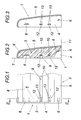
- Fig. 1
- ein erfindungsgemäß auf eine Profilleiste aufgestecktes Formstück in einer Rückansicht,
- Fig. 2
- einen Schnitt nach der Linie II-II der
Fig. 1 , - Fig. 3
- das Formstück ohne Profilleiste in einem der Linie II-II der
Fig. 1 entsprechenden Schnitt , - Fig. 4
- ein ein Außeneck bildendes Formstück mit den anschließenden Profilleisten in einer vereinfachten, zum Teil aufgerissenen Draufsicht,
- Fig. 5
- einen Schnitt nach der Linie IV-IV der
Fig. 4 , - Fig. 6
- eine Draufsicht auf ein ein Inneneck bildendes Formstück mit angeschlossenen Profilleisten,
- Fig. 7
- einen Schnitt nach der Linie VII-VII der
Fig. 6 , - Fig. 8
- eine weitere Ausführungsform eines erfindungsgemäßen Formstückes zwischen zwei Profilleisten in einer Draufsicht und
- Fig. 9
- einen Schnitt nach der Linie IX-IX der
Fig. 8 .
- Fig. 1
- a fitting plugged onto a profile strip according to the invention in a rear view,
- Fig. 2
- a section along the line II-II of
Fig. 1 . - Fig. 3
- the fitting without profile strip in one of the line II-II of
Fig. 1 appropriate cut, - Fig. 4
- a forming a Außeneck forming mold with the subsequent profile strips in a simplified, partially torn plan view,
- Fig. 5
- a section along the line IV-IV of
Fig. 4 . - Fig. 6
- a plan view of an inner corner forming fitting with connected moldings,
- Fig. 7
- a section along the line VII-VII of
Fig. 6 . - Fig. 8
- a further embodiment of a fitting according to the invention between two moldings in a plan view and
- Fig. 9
- a section along the line IX-IX of
Fig. 8 ,
Das Formstück 1 gemäß dem Ausführungsbeispiel nach
Das Formstück 1 bildet zwischen dem Randsteg 5 und den Anschlägen 6 eine Steckaufnahme für den stirnseitigen Endabschnitt 2 der Profilleiste 3, die in dieser Steckaufnahme formschlüssig gehalten werden soll. Damit Verlagerungen des Formstückes 1 gegenüber der Profilleiste, insbesondere der Höhe nach ausgeschlossen werden können, ist das Formstück 1 zwischen den Anschlägen 6 zusätzlich mit zwei Klemmansätzen 12 versehen, die von der Stirnseite her in die Längsnuten 10 der Profilleiste 3 eingreifen und je aus zwei Klemmansätzen 13 bestehen, die durch einen in Richtung der Längsnutung 9 verlaufenden Spalt voneinander getrennt sind, wie dies insbesondere der
Das Formstück 1 nach den
Wie die
Nach den
Claims (3)
Applications Claiming Priority (1)
| Application Number | Priority Date | Filing Date | Title |
|---|---|---|---|
| AT0085406U AT9912U1 (en) | 2006-12-07 | 2006-12-07 | PUT ON A PROFILE STRIP FORM |
Publications (2)
| Publication Number | Publication Date |
|---|---|
| EP1930526A2 true EP1930526A2 (en) | 2008-06-11 |
| EP1930526A3 EP1930526A3 (en) | 2010-03-17 |
Family
ID=39154351
Family Applications (1)
| Application Number | Title | Priority Date | Filing Date |
|---|---|---|---|
| EP07450226A Withdrawn EP1930526A3 (en) | 2006-12-07 | 2007-12-06 | Moulded cap for strip |
Country Status (2)
| Country | Link |
|---|---|
| EP (1) | EP1930526A3 (en) |
| AT (1) | AT9912U1 (en) |
Cited By (2)
| Publication number | Priority date | Publication date | Assignee | Title |
|---|---|---|---|---|
| JP2010112165A (en) * | 2008-11-05 | 2010-05-20 | Frank Sondermann | Base board for covering fringe of covering member and connection member for the base board |
| JP2014070360A (en) * | 2012-09-28 | 2014-04-21 | Panasonic Corp | A set of baseboards |
Citations (2)
| Publication number | Priority date | Publication date | Assignee | Title |
|---|---|---|---|---|
| DE29809577U1 (en) * | 1998-05-28 | 1998-10-01 | Huelsta Werke Huels Kg | Narrow end cap for decorative strips |
| DE10149408C1 (en) * | 2001-10-06 | 2003-01-09 | Xaver Gruenwald Gmbh | Device for fixing border rails comprises a mounting rail and a border rail connected to an intermediate rail using a socket connection designed so that the border rail and the mounting rail are connected in the same insertion direction |
-
2006
- 2006-12-07 AT AT0085406U patent/AT9912U1/en not_active IP Right Cessation
-
2007
- 2007-12-06 EP EP07450226A patent/EP1930526A3/en not_active Withdrawn
Patent Citations (2)
| Publication number | Priority date | Publication date | Assignee | Title |
|---|---|---|---|---|
| DE29809577U1 (en) * | 1998-05-28 | 1998-10-01 | Huelsta Werke Huels Kg | Narrow end cap for decorative strips |
| DE10149408C1 (en) * | 2001-10-06 | 2003-01-09 | Xaver Gruenwald Gmbh | Device for fixing border rails comprises a mounting rail and a border rail connected to an intermediate rail using a socket connection designed so that the border rail and the mounting rail are connected in the same insertion direction |
Cited By (4)
| Publication number | Priority date | Publication date | Assignee | Title |
|---|---|---|---|---|
| JP2010112165A (en) * | 2008-11-05 | 2010-05-20 | Frank Sondermann | Base board for covering fringe of covering member and connection member for the base board |
| EP2184423A3 (en) * | 2008-11-05 | 2010-12-08 | Frank Sondermann | Baseboard for covering the edge of a facing |
| US8122658B2 (en) | 2008-11-05 | 2012-02-28 | Kueberit Profile Systems GmbH & Co. KG | Reversible baseboard for covering a flooring border |
| JP2014070360A (en) * | 2012-09-28 | 2014-04-21 | Panasonic Corp | A set of baseboards |
Also Published As
| Publication number | Publication date |
|---|---|
| EP1930526A3 (en) | 2010-03-17 |
| AT9912U1 (en) | 2008-05-15 |
Similar Documents
| Publication | Publication Date | Title |
|---|---|---|
| DE2623709A1 (en) | COMPONENT SET | |
| DE102012102339A1 (en) | Connection for elastic or plate-shaped components, profile slides and floor coverings | |
| EP1948459B1 (en) | Window unit having decorative strip mounted thereon | |
| DE102007020271A1 (en) | Floor panel connector, has catch lug extending over area of longitudinal edges or front sides of panel, and locking part formed by circumference wall of window, where locking lug or catch lug extends through locking part in locked condition | |
| DE202007001781U1 (en) | drawer | |
| DE102015108275A1 (en) | Corner panel for hollow profile corner connectors, corner connectors, corner connector kit, frame structure and protective grille | |
| EP2991170B1 (en) | Assembly with modular parts and adjustable coding means | |
| DE3733329C1 (en) | Cable guide channel for receiving high voltage, low voltage and telecommunication cables | |
| WO2010102735A1 (en) | Panel | |
| EP3100641B1 (en) | Drawer rear panel, drawer and furniture with drawer | |
| EP0127030A2 (en) | Corner joint | |
| EP1930526A2 (en) | Moulded cap for strip | |
| DE3230100C2 (en) | Insert frame for converting a single-glazed casement frame of a window to double glazing | |
| DE102004059017B4 (en) | Box spring clamp with a arranged on a first box wall clamping leg | |
| DE102009052761A1 (en) | Window lifter for motor vehicle, has bracket and guide rail fastened on bracket, where form-fit fastening units are provided for fastening guide rail on bracket | |
| DE10322633B3 (en) | Rail arrangement for covering or bridging joints, especially for floors | |
| EP2620579B1 (en) | Connection element for connecting profile sections | |
| DE2446912C3 (en) | Electrical assembly for mounting in an electrical system | |
| EP1646756B1 (en) | Connecting system for profiled rails | |
| DE3200282C2 (en) | ||
| DE102010060672B4 (en) | Window or door frame | |
| DE102006051829A1 (en) | Holding system for linear objects such as tubes and hoses has grooves with projections to couple units together by sprung bars | |
| EP2090789B1 (en) | Connector for trough shaped profile bars and connection arrangement | |
| DE639459C (en) | Captive pressure piece on screws, especially for clamping electrical wires | |
| DE19520416C2 (en) | Jack |
Legal Events
| Date | Code | Title | Description |
|---|---|---|---|
| PUAI | Public reference made under article 153(3) epc to a published international application that has entered the european phase |
Free format text: ORIGINAL CODE: 0009012 |
|
| AK | Designated contracting states |
Kind code of ref document: A2 Designated state(s): AT BE BG CH CY CZ DE DK EE ES FI FR GB GR HU IE IS IT LI LT LU LV MC MT NL PL PT RO SE SI SK TR |
|
| AX | Request for extension of the european patent |
Extension state: AL BA HR MK RS |
|
| PUAL | Search report despatched |
Free format text: ORIGINAL CODE: 0009013 |
|
| AK | Designated contracting states |
Kind code of ref document: A3 Designated state(s): AT BE BG CH CY CZ DE DK EE ES FI FR GB GR HU IE IS IT LI LT LU LV MC MT NL PL PT RO SE SI SK TR |
|
| AX | Request for extension of the european patent |
Extension state: AL BA HR MK RS |
|
| AKY | No designation fees paid | ||
| STAA | Information on the status of an ep patent application or granted ep patent |
Free format text: STATUS: THE APPLICATION IS DEEMED TO BE WITHDRAWN |
|
| REG | Reference to a national code |
Ref country code: DE Ref legal event code: 8566 |
|
| 18D | Application deemed to be withdrawn |
Effective date: 20100701 |