EP0127030A2 - Corner joint - Google Patents
Corner joint Download PDFInfo
- Publication number
- EP0127030A2 EP0127030A2 EP84105296A EP84105296A EP0127030A2 EP 0127030 A2 EP0127030 A2 EP 0127030A2 EP 84105296 A EP84105296 A EP 84105296A EP 84105296 A EP84105296 A EP 84105296A EP 0127030 A2 EP0127030 A2 EP 0127030A2
- Authority
- EP
- European Patent Office
- Prior art keywords
- recess
- profile rail
- profile
- corner connector
- rail
- Prior art date
- Legal status (The legal status is an assumption and is not a legal conclusion. Google has not performed a legal analysis and makes no representation as to the accuracy of the status listed.)
- Granted
Links
- 238000004080 punching Methods 0.000 claims description 4
- 238000004519 manufacturing process Methods 0.000 abstract description 11
- 238000010276 construction Methods 0.000 description 2
- 229910052751 metal Inorganic materials 0.000 description 2
- 239000002184 metal Substances 0.000 description 2
- 238000000034 method Methods 0.000 description 2
- 230000002411 adverse Effects 0.000 description 1
- 229910052782 aluminium Inorganic materials 0.000 description 1
- XAGFODPZIPBFFR-UHFFFAOYSA-N aluminium Chemical compound [Al] XAGFODPZIPBFFR-UHFFFAOYSA-N 0.000 description 1
- 238000006073 displacement reaction Methods 0.000 description 1
- 238000001125 extrusion Methods 0.000 description 1
- 238000010438 heat treatment Methods 0.000 description 1
- 238000009434 installation Methods 0.000 description 1
- 238000005192 partition Methods 0.000 description 1
- 239000004033 plastic Substances 0.000 description 1
- 239000012815 thermoplastic material Substances 0.000 description 1
Images

Classifications
-
- F—MECHANICAL ENGINEERING; LIGHTING; HEATING; WEAPONS; BLASTING
- F16—ENGINEERING ELEMENTS AND UNITS; GENERAL MEASURES FOR PRODUCING AND MAINTAINING EFFECTIVE FUNCTIONING OF MACHINES OR INSTALLATIONS; THERMAL INSULATION IN GENERAL
- F16B—DEVICES FOR FASTENING OR SECURING CONSTRUCTIONAL ELEMENTS OR MACHINE PARTS TOGETHER, e.g. NAILS, BOLTS, CIRCLIPS, CLAMPS, CLIPS OR WEDGES; JOINTS OR JOINTING
- F16B12/00—Jointing of furniture or the like, e.g. hidden from exterior
- F16B12/44—Leg joints; Corner joints
- F16B12/50—Metal corner connections
-
- Y—GENERAL TAGGING OF NEW TECHNOLOGICAL DEVELOPMENTS; GENERAL TAGGING OF CROSS-SECTIONAL TECHNOLOGIES SPANNING OVER SEVERAL SECTIONS OF THE IPC; TECHNICAL SUBJECTS COVERED BY FORMER USPC CROSS-REFERENCE ART COLLECTIONS [XRACs] AND DIGESTS
- Y10—TECHNICAL SUBJECTS COVERED BY FORMER USPC
- Y10T—TECHNICAL SUBJECTS COVERED BY FORMER US CLASSIFICATION
- Y10T403/00—Joints and connections
- Y10T403/46—Rod end to transverse side of member
- Y10T403/4602—Corner joint
-
- Y—GENERAL TAGGING OF NEW TECHNOLOGICAL DEVELOPMENTS; GENERAL TAGGING OF CROSS-SECTIONAL TECHNOLOGIES SPANNING OVER SEVERAL SECTIONS OF THE IPC; TECHNICAL SUBJECTS COVERED BY FORMER USPC CROSS-REFERENCE ART COLLECTIONS [XRACs] AND DIGESTS
- Y10—TECHNICAL SUBJECTS COVERED BY FORMER USPC
- Y10T—TECHNICAL SUBJECTS COVERED BY FORMER US CLASSIFICATION
- Y10T403/00—Joints and connections
- Y10T403/55—Member ends joined by inserted section
- Y10T403/555—Angle section
Definitions
- the invention relates to a device, in particular a mirror cabinet, with a first and a second profile rail, each of which has a hollow chamber, and with a corner connector, which is inserted into the hollow chamber of the first and second profile rail with a first and second pin .
- the pins of the corner connector have teeth on their outer surface. After being inserted into the hollow chambers of the profile rails, these toothings snap into the toothing provided there or into toothing to be inserted there.
- the profile rails are made of a thermoplastic material, which allows the production of the teeth mentioned.
- the manufacture of the teeth in the interior of the hollow chamber is nevertheless associated with a comparatively large production outlay, especially since suitable tools are introduced into the hollow chambers and the teeth are finally created by heating.
- there are limits especially since there are no special securing elements or additional fastening elements between the profiled rails and corner connector or its pin.
- Swiss patent specification 350 091 describes a corner connection of plate-shaped elements which have interlocking guide surfaces on their longitudinal edges. These guide surfaces are designed in the manner of a tongue and groove connection, the plate-shaped elements being connected to one another by means of further connecting elements, specifically in the form of fittings and head pins.
- Such a corner connection is hardly suitable for connecting profile rails with comparatively small end faces, especially since particular stability and dimensional stability can hardly be achieved. Furthermore, processing of the end faces of the profile rails to be connected, which would be comparable with the known corner connection, would require a not inconsiderable amount of work.
- the patent according to economic patent 58 800 of the German Democratic Republic describes a metal cupboard that can be produced in a plug-in construction, the side walls of which each have tabs in the form of feet on the underside. There is a base plate with slots into which the said feet of the side walls engage, a relative displacement of the side wall with respect to the base plate having to take place during assembly.
- a corner connector of the type mentioned at the beginning cannot readily be used in the known metal cabinet, especially since a corner connector cannot allow the required relative movement.
- German utility model 77 11 771 teaches a kit for shelves or the like, which contains a base plate with a multi-angled fitting part.
- An associated side wall also has a corresponding fitting part. The production and the connection of the mentioned fitting parts with the base plate or the side wall require a correspondingly large production and assembly effort.
- the invention is therefore based on the object of improving a device of the type mentioned at a low cost and production outlay in such a way that a high degree of stability and dimensional accuracy is ensured in the connection area of the profile rails.
- the device should have a long service life and be distinguished by a high level of functional reliability.
- the device should have high stability even with small dimensions of the profile rails and in particular with a small wall thickness and should be able to be assembled in a simple manner.
- the device is also intended to ensure a stable connection of the profiled rails which can be produced with little assembly effort. Finally, the device should be able to meet the operational requirements and conditions.
- the second profile rail have an extension which is inserted through an opening of the first profile rail and through an opening of the first pin. Furthermore, the first pin contains a first recess and the mentioned extension of the second profile rail has a second recess, a connecting element engaging through the two recesses.
- the device according to the invention is characterized by a simple and inexpensive construction and enables a dimensionally stable and exact connection thereof even with small dimensions of the profile rails. Since the approach is inserted into the openings of the corner connector and the first profile rail, there is a defined alignment and definition. Furthermore, the approach mentioned is by means of the verb tion element, in particular screw or grooved pin, firmly connected to the corner connector, so that overall a reliable and reliable connection is created.
- the device can be assembled with a comparatively small amount of assembly work, only the attachment of the second profile rail having to be passed through the two openings of the corner connector and the first profile rail and finally the final and firm connection only having to be made with the connecting element.
- the device can be assembled in the form of a frame from a total of four profile rails, which are connected at their ends in the manner according to the invention.
- mirror cabinets are mentioned as the preferred area of use, the device according to the invention can also be used in other areas of application, and it is only mentioned here by way of example of frames for shower partitions, windows or doors.
- the connecting element also engages in the two recesses of the pin and of the shoulder, as a result of which the corner connector and the second profile rail are mutually fixed. Furthermore, since the mentioned pin of the corner connector is inserted into the first profile rail and the said extension is passed through the opening of the first profile rail, a defined fixation of the first profile rail is also ensured.
- the corner connector is connected directly to the second profile rail by means of the connecting element. Since the approach of the second profile rail is also guided through the above-mentioned openings of the first profile rail and the corner connector, which in turn is inserted into the first profile rail, a stable and accurate connection of the two profile rails is ensured overall with little effort.
- the above-mentioned recesses of the pin and extension of the second profile rail run essentially in the direction of the longitudinal axis of the first profile rail.
- a reliable fixation can be achieved due to the parallelism of the recess, pin and first profile rail, without the corner connector itself being decisively weakened and its load-bearing capacity being adversely affected.
- it is of crucial importance that, by simply inserting an attachment of the one profile rail into said and aligned openings of the corner connector and other profile rail, an exact and dimensionally accurate alignment is achieved and a permanent and functional connection is created on the basis of the screw or the like .
- the profile rails themselves do not require any screw channels extending over their entire length, since the connecting element is connected to the corner connector according to the invention.
- the geometric axis of the recess in the mentioned approach to the geometric axis of the recess in the corner connector has a predetermined distance from an end edge of the second profile rail, said end edge on an inner surface of the first profile rail or of the corner connector.
- the distance mentioned is in the range between 0.1 and 1.0 mm.
- the connecting element can be inserted into the said recesses from the outside of the profile rails.
- the second profile rail has on its outside, at least in the region of the attachment, an edge set back with respect to the same.
- the recesses are thus directly accessible from the outside, and the connecting element can be inserted directly into the easily accessible recesses and anchored or screwed or otherwise fastened there. This is of particular importance in view of the limited space available in comparatively small mirror cabinets, in which screws or the like previously had to be fastened from the inside.
- the approach and / or the recess of the second profile rail and / or the opening of the first profile rail are produced by punching out in a preferred embodiment.
- the profiled rails cut to the required length only have to be subjected to a punching process which can be carried out in a short amount of time.
- the end faces and / or the inner webs of the profiled rails have a predetermined distance from the outer webs of the respective other profiled rails.
- the inner webs each end inside the other profile rail.
- a special processing of the end faces, in particular after punching out, is not necessary.
- the outer webs are visible from the outside of the device, while the end faces of the inner webs mentioned are hidden.
- a facing element is arranged in the corner area between the outer webs. With this facing element, the edges of the outer webs are covered, so that overall there is a harmonious and self-contained device.
- the facing element also covers the connection element located according to the invention behind the outer webs or inside the profile rail.
- the facing element For a reliable connection of the facing element, it is either fastened in the corner area by means of a screw or the like or else clipped on via a snap connection.
- the snap connection which is preferably provided and which has latching elements or the like which engage behind, enables quick and easy installation.
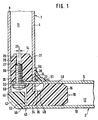
- first profile rail 1 and a second profile rail 2 of the device which are arranged at right angles to one another.
- the rails 1 and 2 each have an inner web 4, 6 and an outer web 8, 10. Between the webs mentioned are hollow chambers 11, 12, in which right-angled pins 14, 16 of a corner connector 18 are inserted.
- the second profile rail 2 has a projection 20 which extends through an opening 22 of the inner web 4 of the profile rail 1. Furthermore, the projection 20 is passed through an aligned opening 24 of the pin 14 from the corner connector 18.
- the first pin 14 of the corner connector 18 has a first recess 28.
- the extension 20 has in the region of the hollow chamber 11 of the profile rail 1 a second recess 26 which is substantially flush with the recess 28 of the said pin 14.
- the geometric axis 27 of the second recess 26 is arranged at a predetermined distance 25 from the geometric axis 29 of the first recess 28 in the corner connector 18, specifically in the direction of the inner surface 31 of the first profile rail.
- a connecting element 30, here in the form of a screw, is introduced into the said recesses 26, 28.
- the end face 32 of the extension 20 and also the end face 34 of the inner web 4 of the first profile rail 1 are each at a predetermined distance with respect to the outer webs 8 and 10.
- the end face 34 protrudes into a recess 36 of the corner connector 18.
- a facing element 42 is provided on the outside 40, which partially abuts the end edges 44, 46 of the two outer webs 8, 10.
- the corner connector 18 with its pin 14 is first inserted into the hollow chamber 11 of the profile rail 1.
- the end face 34 lies on the bottom face 48 of the corner connector 18, as a result of which a defined alignment is achieved.
- the inner web 6 of the second profile rail lies directly on the surface 49 of the pin 16 or it is guided in the opening 24 of the corner connector 18.
- the opening 22 and the lower end 51 of the inner web 4 of the first profile rail are designed accordingly, so that tension can also be achieved in this respect.
- the second profile rail 2 is added in such a way that the projection 20 is pushed through the aligned openings 22, 24.
- the connecting element 30 is inserted from the outside 40 into the aligned recesses 26, 28 in the pin 14 of the corner connector 18.
- the connecting element 30 is designed here as a screw which is screwed into the recess 28 in a simple manner, with a rotation lock subsequently being achieved by means of a spring ring 50.
- the corner connector 18 has, in the outer corner area, a longitudinal groove 52 extending perpendicular to the plane of the drawing, in which the head of the connecting element 30 and also the facing element 42 are located. This longitudinal groove 52, like the edges 44 and 46, is covered by means of the facing element 42.
- the facing element can be screwed on by means of a screw. Alternatively, a snap connection can also be provided in order to clip in the facing element 42 in the corner region.
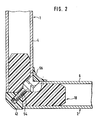
- FIG. 2 shows the device in another sectional plane, the veneer element 42 now being screwed onto the corner connector 18 by means of a screw 54.
- the above-mentioned recess 36 has been expanded somewhat so that the screw 54 can be screwed in from the inside.
- the profile rails 1, 2 and their inner webs 4, 6 are also shortened in the manner shown in the area of this screw 54.
- an internally rounded cover strip 56 which, according to the invention, extends over the entire depth of the profile rails, i.a. the opening for the screw 54 between the inner webs 4, 6 is also covered.
- FIG 3 shows the first profile rail 1 with two openings 22.
- the corner connector 18 also has two openings 24.
- the position of the cuts according to FIGS. 1 and 2 is indicated by the section line I or II.
- the profile rail 2 also has two lugs 20, by means of which, in cooperation with the corner connector 18, the connection to the profile rail 1 already explained in detail above is achieved.
- the corner connector 18 extends practically over the entire width of the two rails 1 and 2. Since the corner connector 18 engages with its pegs in the hollow chambers of the profile rails 1 and 2 over a width which is large according to the invention, a defined alignment of the two profile rails 1 and 2 is ensured.
- the second profile rail 2 lies with its end edge 58 in the assembled state on the inner surface 31 of the first profile rail. Due to the above-described offset of the geometric axes of the recess 26 and the recess in the corner connector 18, the end edge 58 is pressed against the inner surface 31.
- the distance mentioned is approximately in the range between 0.1 and 1.0 mm, so that the manufacturing-related tolerances etc. can be compensated for without difficulty in order to obtain a play-free connection.
- the end edge 58 could also lie directly against the inner surface 60 of the corner connector 18 in a variant which is not shown here, the aforementioned distance of the recess likewise being present. It can be seen that here too a bracing of the corner connector and profile rail 2 is achieved.
Abstract
Die Erfindung bezieht sich auf eine Vorrichtung, insbesondere einen Spiegelschrank, mit Profilschienen (1, 2), welche mittels eines Eckverbinders (18) mit Zapfen (14, 16), bevorzugt rechtwinklig, verbunden sind. Die Herstellung und Montage einer derartigen Vorrichtung erforderte bisher, insbesondere bei beengten Platzverhältnissen, einen vergleichsweise großen Aufwand. Es ergaben sich Schwierigkeiten, um mit geringem Aufwand eine hohe Stabilität und Maßhaltigkeit zu erreichen. Es wird daher vorgeschlagen, daß die zweite Profilschiene (2) ein Ansatz (20) aufweist, der durch eine Öffnung (22) der ersten Profilschiene (1) sowie durch eine Öffnung (24) des ersten Zapfens (14) gesteckt ist. Der genannte erste Zapfen (14) weist eine erste Ausnehmung (28) auf, und der Ansatz (20) weist eine zweite Ausnehmung (26) auf, wobei ein Verbindungselement (30) durch die beiden Ausnehmungen (26, 28) greift.The invention relates to a device, in particular a mirror cabinet, with profile rails (1, 2) which are connected by means of a corner connector (18) to pins (14, 16), preferably at right angles. The manufacture and assembly of such a device has hitherto required a comparatively great outlay, particularly in the case of limited space. Difficulties arose in order to achieve high stability and dimensional accuracy with little effort. It is therefore proposed that the second profile rail (2) have an extension (20) which is inserted through an opening (22) in the first profile rail (1) and through an opening (24) in the first pin (14). Said first pin (14) has a first recess (28) and the extension (20) has a second recess (26), a connecting element (30) extending through the two recesses (26, 28).
Description
Die Erfindung bezieht sich auf eine Vorrichtung, insbesondere einen Spiegelschrank, mit einer ersten und einer zweiten Profilschiene, welche jeweils eine Hohlkammer aufweisen, und mit einem Eckverbinder, der mit einem ersten bzw. zweiten Zapfen in die Hohlkammer der ersten bzw. zweiten Profilschiene hineingesteckt ist.The invention relates to a device, in particular a mirror cabinet, with a first and a second profile rail, each of which has a hollow chamber, and with a corner connector, which is inserted into the hollow chamber of the first and second profile rail with a first and second pin .
In der österreichischen Patentschrift 307 656 ist eine Vorrichtung beschrieben, bei welcher die Zapfen des Eckverbinders in ihrer Außenfläche Verzahnungen aufweisen. Diese Verzahnungen rasten nach dem Einstecken in die Hohlkammern der Profilschienen in dort vorgesehene Verzahnungen bzw. in dort einzubringende Verzahnungen ein. Bei der bekannten Vorrichtung bestehen die Profilschienen aus einem thermoplastischen Kunststoff, welcher die Herstellung der genannten Verzahnungen zuläßt. Die Herstellung der Verzahnungen im Inneren der Hohlkammer ist dennoch mit einem vergleichsweise großen Herstellungsaufwand verbunden, zumal geeignete Werkzeuge in die Hohlkammern eingeführt und durch Erwärmung schließlich die Verzahnungen geschaffen werden. Hinsichtlich der Sicherheit und Stabilität der Verbindung sind Grenzen gesetzt, zumal besondere Sicherungselemente oder zusätzliche Befestigungselemente zwischen Profilschienen und Eckverbinder bzw. dessen Zapfen nicht vorhanden sind.In the Austrian patent specification 307 656 a device is described in which the pins of the corner connector have teeth on their outer surface. After being inserted into the hollow chambers of the profile rails, these toothings snap into the toothing provided there or into toothing to be inserted there. In the known device, the profile rails are made of a thermoplastic material, which allows the production of the teeth mentioned. The manufacture of the teeth in the interior of the hollow chamber is nevertheless associated with a comparatively large production outlay, especially since suitable tools are introduced into the hollow chambers and the teeth are finally created by heating. With regard to the security and stability of the connection, there are limits, especially since there are no special securing elements or additional fastening elements between the profiled rails and corner connector or its pin.
In der schweizerischen Patentschrift 350 091 ist eine Eckverbindung von plattenförmigen Elementen beschrieben, welche an ihren Längskanten ineinandergreifende Führungsflächen aufweisen. Diese Führungsflächen sind nach Art einer Nut-Federverbindung ausgebildet, wobei mittels weiteren Verbindungselementen, und zwar in Form von Beschlägen und Kopfstiften, die plattenförmigen Elemente miteinander verbunden sind. Zur Verbindung von Profilschienen mit vergleichsweise kleinen Stirnflächen ist eine solche Eckverbindung kaum geeignet, zumal eine besondere Stabilität und Maßhaltigkeit kaum zu erreichen ist. Ferner würde eine mit der bekannten Eckverbindung vergleichbare Bearbeitung der Stirnflächen der miteinander zu verbindenden Profilschienen einen nicht unerheblichen Arbeitsaufwand erfordern.Swiss patent specification 350 091 describes a corner connection of plate-shaped elements which have interlocking guide surfaces on their longitudinal edges. These guide surfaces are designed in the manner of a tongue and groove connection, the plate-shaped elements being connected to one another by means of further connecting elements, specifically in the form of fittings and head pins. Such a corner connection is hardly suitable for connecting profile rails with comparatively small end faces, especially since particular stability and dimensional stability can hardly be achieved. Furthermore, processing of the end faces of the profile rails to be connected, which would be comparable with the known corner connection, would require a not inconsiderable amount of work.
In der Patentschrift gemäß Wirtschaftspatent 58 800 der Deutschen Demokratischen Republik ist ein in Steckbauweise herstellbarer Metallschrank beschrieben, dessen Seitenwände jeweils an der Unterseite Ansätze in Form von Füßen aufweisen. Es ist eine Bodenplatte mit Schlitzen vorhanden, in welche die genannten Füße der Seitenwände eingreifen, wobei während der Montage eine Relativverschiebung der Seitenwand bezüglich der Bodenplatte erfolgen muß. Ein Eckverbinder der eingangs genannten Art kann bei dem bekannten Metallschrank nicht ohne weiteres zum Einsatz gelangen, zumal ein Eckverbinder die erforderliche Relativbewegung nicht zulassen kann.The patent according to
Ferner ist in dem Deutschen Gebrauchsmuster 74 37 173 ein Schrank beschrieben, dessen Wandteile steckerartig ineinander greifende Zähne und Nuten im Bereich ihrer Verbindungskanten aufweisen. Die Herstellung derartiger Zähne und Nuten ist mit einem beträchtlichen Aufwand an Werkzeugen und Zeit verbunden. Entsprechende Teile müssen nämlich aus den Wandteilen ausgestanzt und nachfolgend in mehreren Arbeitsgängen in einer vorgegebenen Weise gebogen werden. Bei Profilschienen, die in der Regel aus Aluminium im Strangspressverfahren hergestellt werden, ist ein Umbiegen darüberhinaus in der Praxis kaum durchführbar.Furthermore, a cabinet is described in German Utility Model 74 37 173, the wall parts of which have teeth and grooves which engage in one another in the region of their connecting edges. The production of such teeth and grooves is associated with a considerable expenditure of tools and time. Corresponding parts must namely be punched out of the wall parts and subsequently bent in a predetermined manner in several work steps. In the case of profile rails, which are usually made of aluminum using the extrusion process, it is hardly possible to bend them in practice.
Schließlich lehrt das Deutsche Gebrauchsmuster 77 11 771 einen Bausatz für Regale oder dergleichen, welcher eine Bodenplatte mit einem mehrfach abgewinkelten Beschlagteil enthält. Auch eine zugeordnete Seitenwand weist ein entsprechendes Beschlagteil auf. Die Herstellung und die Verbindung der genannten Beschlagteile mit der Bodenplatte bzw. der Seitenwand erfordern einen entsprechend großen Herstellungs- und Montageaufwand.Finally, the German utility model 77 11 771 teaches a kit for shelves or the like, which contains a base plate with a multi-angled fitting part. An associated side wall also has a corresponding fitting part. The production and the connection of the mentioned fitting parts with the base plate or the side wall require a correspondingly large production and assembly effort.
Der Erfindung liegt daher die Aufgabe zugrunde, eine Vorrichtung der genannten Art bei einem geringen Kosten- und Herstellungsaufwand dahingehend zu verbessern, daß eine hohe Stabilität und Maßhaltigkeit im Verbindungsbereich der Profilschienen sicher gestellt wird. Die Vorrichtung soll eine hohe Lebensdauer aufweisen und sich durch eine hohe Funktionssicherheit auszeichnen. Die Vorrichtung soll auch bei kleinen Abmessungen der Profilschienen und insbesondere bei geringer Wanddicke eine hohe Stabilität aufweisen und in einfacher Weise zusammengebaut werden können. Die Vorrichtung soll ferner eine stabile und mit einem geringen Montageaufwand herzustellende Verbindung der Profilschienen gewährleisten. Schließlich soll die Vorrichtung den betrieblichen Anforderungen und Gegebenheiten gewachsen sein.The invention is therefore based on the object of improving a device of the type mentioned at a low cost and production outlay in such a way that a high degree of stability and dimensional accuracy is ensured in the connection area of the profile rails. The device should have a long service life and be distinguished by a high level of functional reliability. The device should have high stability even with small dimensions of the profile rails and in particular with a small wall thickness and should be able to be assembled in a simple manner. The device is also intended to ensure a stable connection of the profiled rails which can be produced with little assembly effort. Finally, the device should be able to meet the operational requirements and conditions.
Zur Lösung dieser Aufgabe wird vorgeschlagen, daß die zweite Profilschiene einen Ansatz aufweist, der durch eine Öffnung der ersten Profilschiene sowie durch eine Öffnung des ersten Zapfens gesteckt ist. Ferner enthält der erste Zapfen eine erste Ausnehmung und der genannte Ansatz der zweiten Profilschiene eine zweite Ausnehmung, wobei ein Verbindungselement durch die beiden Ausnehmungen greift.To achieve this object, it is proposed that the second profile rail have an extension which is inserted through an opening of the first profile rail and through an opening of the first pin. Furthermore, the first pin contains a first recess and the mentioned extension of the second profile rail has a second recess, a connecting element engaging through the two recesses.
Die erfindungsgemäße Vorrichtung zeichnet sich durch einen einfachen und kostengünstigen Aufbau aus und ermöglicht auch bei geringen Abmessungen der Profilschienen eine maßhaltige und exakte Verbindung derselben. Da der Ansatz in die Öffnungen von Eckverbinder und der ersten Profilschiene eingeführt ist, erfolgt insoweit eine definierte Ausrichtung und Festlegung. Ferner wird der genannte Ansatz mittels des Verbindungselementes, insbesondere Schraube oder Kerbstift, mit dem Eckverbinder fest verbunden, so daß insgesamt eine zuverlässige und funktionssichere Verbindung geschaffen ist. Die Vorrichtung kann mit einem vergleichsweise geringen Montageaufwand zusammengebaut werden, wobei lediglich der Ansatz der zweiten Profilschiene durch die beiden Öffnungen von Eckverbinder und der ersten Profilschiene hindurchgeführt werden muß und abschließend nur noch mit dem Verbindungselement die endgültige und feste Verbindung herzustellen ist. Es bedarf keiner besonderen Erwähnung, daß die Vorrichtung ggfs. in Form eines Rahmens aus insgesamt vier Profilschienen zusammengebaut sein kann, welche an ihren Enden in der erfindungsgemäßen Weise miteinander verbunden sind. Obgleich als bevorzugtes Einsatzgebiet Spiegelschränke genannt sind, kann die erfindungsgemäße Vorrichtung auch in anderen Einsatzgebieten zur Anwendung gelangen, und es sei hier nur beispielshaft auf Rahmen von Duschtrennwänden, Fenstern oder Türen hingewiesen.The device according to the invention is characterized by a simple and inexpensive construction and enables a dimensionally stable and exact connection thereof even with small dimensions of the profile rails. Since the approach is inserted into the openings of the corner connector and the first profile rail, there is a defined alignment and definition. Furthermore, the approach mentioned is by means of the verb tion element, in particular screw or grooved pin, firmly connected to the corner connector, so that overall a reliable and reliable connection is created. The device can be assembled with a comparatively small amount of assembly work, only the attachment of the second profile rail having to be passed through the two openings of the corner connector and the first profile rail and finally the final and firm connection only having to be made with the connecting element. It is not necessary to mention that the device can be assembled in the form of a frame from a total of four profile rails, which are connected at their ends in the manner according to the invention. Although mirror cabinets are mentioned as the preferred area of use, the device according to the invention can also be used in other areas of application, and it is only mentioned here by way of example of frames for shower partitions, windows or doors.
Aufgrund der Anordnung der bevorzugt rechtwinklig verlaufenden Zapfen der Profilschienen wird zunächst eine formschlüssige und exakte Ausrichtung erreicht. Das Verbindungselement greift erfindungsgemäß ferner in die beiden Ausnehmungen des Zapfens sowie des Ansatzes ein, wodurch eine gegenseitige Fixierung von Eckverbinder und zweiter Profilschiene erfolgt. Da ferner der genannte Zapfen des Eckverbinders in die erste Profilschiene eingeführt ist und der besagte Ansatz durch die Öffnung der ersten Profilschiene hindurchgeführt ist, wird auch eine definierte Fixierung der ersten Profilschiene gewährleistet. Mittels des Verbindungselementes ist der Eckverbinder unmittelbar mit der zweiten Profilschiene verbunden. Da der Ansatz der zweiten Profilschiene zugleich auch durch die genannten Öffnungen der ersten Profilschiene und des Eckverbinders geführt sind, welcher seinerseits in die erste Profilschiene eingeschoben ist, ist insgesamt eine stabile und maßgerechte Verbindung der beiden Profilschienen mit einem geringen Aufwand sichergestellt.Due to the arrangement of the preferably rectangular pins of the profile rails, a positive and precise alignment is achieved first. According to the invention, the connecting element also engages in the two recesses of the pin and of the shoulder, as a result of which the corner connector and the second profile rail are mutually fixed. Furthermore, since the mentioned pin of the corner connector is inserted into the first profile rail and the said extension is passed through the opening of the first profile rail, a defined fixation of the first profile rail is also ensured. The corner connector is connected directly to the second profile rail by means of the connecting element. Since the approach of the second profile rail is also guided through the above-mentioned openings of the first profile rail and the corner connector, which in turn is inserted into the first profile rail, a stable and accurate connection of the two profile rails is ensured overall with little effort.
Um auch bei geringen Abmessungen eine zuverlässige Verbindung zu erhalten, verlaufen die genannten Ausnehmungen von Zapfen und Ansatz der zweiten Profilschiene im wesentlichen in Richtung der Längsachse der ersten Profilschiene. Auch bei kleinen Abmessungen des Eckverbinders kann aufgrund der Parallelität von Ausnehmung, Zapfen sowie erster Profilschiene eine zuverlässige Fixierung erreicht werden, ohne daß hierdurch der Eckverbinder selbst entscheidend geschwächt und in seiner Tragfähigkeit nachteilig beeinflußt wird. In allen Anwendungsfällen ist es von maßgebender Bedeutung, daß durch einfaches Einführen eines Ansatzes der einen Profilschiene in die besagten und miteinander fluchtenden öffnungen von Eckverbinder und anderer Profilschiene eine exakte und maßhaltige Ausrichtung erreicht wird und aufgrund der Schraube oder dergleichen eine dauerhafte und funktionsgerechte Verbindung geschaffen wird. Ferner sei hervorgehoben, daß die Profilschienen selbst keine sich über ihre Gesamtlänge erstreckenden Schraubkanäle erfordern, da das Verbindungselement erfindungsgemäß mit dem Eckverbinder verbunden ist.In order to obtain a reliable connection even with small dimensions, the above-mentioned recesses of the pin and extension of the second profile rail run essentially in the direction of the longitudinal axis of the first profile rail. Even with small dimensions of the corner connector, a reliable fixation can be achieved due to the parallelism of the recess, pin and first profile rail, without the corner connector itself being decisively weakened and its load-bearing capacity being adversely affected. In all applications, it is of crucial importance that, by simply inserting an attachment of the one profile rail into said and aligned openings of the corner connector and other profile rail, an exact and dimensionally accurate alignment is achieved and a permanent and functional connection is created on the basis of the screw or the like . It should also be emphasized that the profile rails themselves do not require any screw channels extending over their entire length, since the connecting element is connected to the corner connector according to the invention.
Um eine spielfreie Verbindung zu gewährleisten, weist in einer wesentlichen Ausgestaltung die geometrische Achse der Ausnehmung in dem genannten Ansatz zur geometrischen Achse der Ausnehmung im Eckverbinder einen vorgegebenen Abstand zu einer Stirnkante der zweiten Profilschiene auf, wobei die genannte Stirnkante an einer Innenfläche der ersten Profilschiene oder des Eckverbinders anliegt. Der genannte Abstand liegt im Rahmen der Erfindung im Bereich zwischen 0,1 und 1,0 mm. Während der Montage wird beim Einführen des Verbindungselements aufgrund des genannten Abstandes die zweite Profilschiene bezüglich der ersten Profilschiene oder aber auch des Eckverbinders verspannt. Es wird also in besonders einfacher Weise ein Toleranzausgleich erreicht und die derart montierten Profilschienen sind spielfrei miteinander verbunden. Der bevorzugt aus Kunststoff gefertigte Eckverbinder und auch die Profilschienen weisen eine hinreichende Elastizität und Nachgiebigkeit auf, so daß auch das Einführen des Befestigungselementes ohne besondere Schwierigkeiten vorgenommen werden kann.In order to ensure a play-free connection, the geometric axis of the recess in the mentioned approach to the geometric axis of the recess in the corner connector has a predetermined distance from an end edge of the second profile rail, said end edge on an inner surface of the first profile rail or of the corner connector. Within the scope of the invention, the distance mentioned is in the range between 0.1 and 1.0 mm. During assembly, when the connecting element is inserted, the second profile rail is braced with respect to the first profile rail or else the corner connector due to the distance mentioned. Tolerance compensation is thus achieved in a particularly simple manner and the profiled rails mounted in this way are connected to one another without play. The corner connector, which is preferably made of plastic, and also the profiled rails have sufficient elasticity and resilience, so that the fastening element can also be inserted without any particular difficulties.
Damit die Montage schnell und mit einem geringen Aufwand durchführbar ist, ist das Verbindungselement von der Außenseite der Profilschienen her in die besagten Ausnehmungen einführbar. Hierbei weist die zweite Profilschiene an ihrer Außenseite zumindest im Bereich des Ansatzes eine bezüglich desselben zurückversetzte Kante auf. Die Ausnehmungen sind somit von der Außenseite her unmittelbar zugänglich, und das Verbindungselement kann in die leicht zugänglichen Ausnehmungen direkt eingesetzt und dort verankert bzw. festgeschraubt oder sonstwie befestigt werden. Dies ist gerade im Hinblick auf beengte Platzverhältnisse bei vergleichsweise kleinen Spiegelschränken von maßgebender Bedeutung, bei welchen bisher Schrauben oder dergleichen von der Innenseite her befestigt werden mußten.So that the assembly can be carried out quickly and with little effort, the connecting element can be inserted into the said recesses from the outside of the profile rails. Here, the second profile rail has on its outside, at least in the region of the attachment, an edge set back with respect to the same. The recesses are thus directly accessible from the outside, and the connecting element can be inserted directly into the easily accessible recesses and anchored or screwed or otherwise fastened there. This is of particular importance in view of the limited space available in comparatively small mirror cabinets, in which screws or the like previously had to be fastened from the inside.
Um eine rationelle und kostengünstige Fertigung zu erhalten, sind in einer bevorzugten Ausführungsform der Ansatz und/oder die Ausnehmung der zweiten Profilschiene und/oder die Öffnung der ersten Profilschiene durch Ausstanzen hergestellt. Die auf die erforderliche Länge geschnittenen Profilschienen müssen lediglich einem Stanzvorgang unterworfen werden, der mit einem geringen Zeitaufwand durchführbar ist. Hierbei sind keine allzu hohen Anforderungen im Hinblick auf Maßgenauigkeit usw. zu berücksichtigen, wie es beispielsweise im Falle von Gehrungsverbindungen erforderlich ist. Aufgrund des erfindungsgemäßen Ineinandergreifens der Profilschienen einerseits und des Eckverbinders andererseits wird gleichwohl eine äußerste exakte und maßhaltige Vorrichtung geschaffen.In order to obtain efficient and cost-effective production, the approach and / or the recess of the second profile rail and / or the opening of the first profile rail are produced by punching out in a preferred embodiment. The profiled rails cut to the required length only have to be subjected to a punching process which can be carried out in a short amount of time. Here, there are no too high requirements with regard to dimensional accuracy, etc., as is required, for example, in the case of miter connections. Due to the interlocking of the profile rails on the one hand and the corner connector on the other hand, an extremely exact and dimensionally accurate device is nevertheless created.
In einer besonderen Ausgestaltung weisen der Ansatz und/oder die inneren Stege der Profilschienen mit ihren Stirnflächen einen vorgegebenen Abstand zu den äußeren Stegen der jeweils anderen Profilschienen auf. Mit anderen Worten, die inneren Stege enden jeweils im Inneren der jeweils anderen Profilschiene. Eine besondere Bearbeitung der Stirnflächen insbesondere nach dem Ausstanzen ist nicht erforderlich. Von außen sind von der Vorrichtung die äußeren Stege sichtbar, während die genannten Stirnflächen der inneren Stege verdeckt liegen. In einer zweckmäßigen Ausgestaltung ist in dem Eckbereich zwischen den äußeren Stegen ein Verblendungselement angeordnet. Mit diesem Verblendungselement werden also die Kanten der äußeren Stege abgedeckt, so daß insgesamt eine harmonische und in sich geschlossene Vorrichtung vorliegt. Das Verblendungselement deckt ferner auch das erfindungsgemäß hinter den äußeren Stegen bzw. im Inneren der Profilschiene befindliche Verbindungselement ab.In a special embodiment, the end faces and / or the inner webs of the profiled rails have a predetermined distance from the outer webs of the respective other profiled rails. In other words, the inner webs each end inside the other profile rail. A special processing of the end faces, in particular after punching out, is not necessary. The outer webs are visible from the outside of the device, while the end faces of the inner webs mentioned are hidden. In an expedient embodiment, a facing element is arranged in the corner area between the outer webs. With this facing element, the edges of the outer webs are covered, so that overall there is a harmonious and self-contained device. The facing element also covers the connection element located according to the invention behind the outer webs or inside the profile rail.
Zur zuverlässigen Verbindung des Verblendungselements ist dieses im Eckbereich entweder mittels einer Schraube oder dergleichen befestigt oder aber über eine Schnapp-Verbindung eingeclipst. Die bevorzugt vorgesehene Schnapp-Verbindung, welche hintergriffige Rastelemente oder dergleichen aufweist, ermöglicht eine schnelle und einfache Montage.For a reliable connection of the facing element, it is either fastened in the corner area by means of a screw or the like or else clipped on via a snap connection. The snap connection, which is preferably provided and which has latching elements or the like which engage behind, enables quick and easy installation.
Die Erfindung wird nachfolgend anhand der Zeichnung näher erläutert. Es zeigen:
- Fig. 1 einen Schnitt durch die Vorrichtung mit zwei Profilschienen,
- Fig. 2 einen Schnitt durch die Vorrichtung gemäß Fig. 1, jedoch in einer anderen Schnittebene,
- Fig. 3 in einer explosionsartigen Darstellung eine geringfügig abgewandelten Ausführungsform, wobei hier auch die Schnittebenen von Fig. 1 und 2 angedeutet sind.
- 1 shows a section through the device with two rails,
- 2 shows a section through the device according to FIG. 1, but in a different sectional plane,
- Fig. 3 shows an exploded view of a slightly modified embodiment, the sectional planes of Fig. 1 and 2 are also indicated here.
Fig. 1 zeigt von der Vorrichtung eine erste Profilschiene 1 sowie eine zweite profilschiene 2, die rechtwinkelig zueinander angeordnet sind. Die Profilschienen 1 und 2 weisen jeweils einen inneren Steg 4, 6 sowie einen äußeren Steg 8, 10 auf. Zwischen den genannten Stegen befinden sich Hohlkammern 11, 12, in welche rechtwinkelig angeordnete Zapfen 14, 16 eines Eckverbinders 18 eingesetzt sind.1 shows a
Die zweite Profilschiene 2 weist einen Ansatz 20 auf, der durch eine Öffnung 22 des inneren Steges 4 der Profilschiene 1 durchgreift. Ferner ist der Ansatz 20 durch eine fluchtende Öffnung 24 des Zapfens 14 vom Eckverbinder 18 hindurchgeführt. Der erste Zapfen 14 des Eckverbinders 18 weist eine erste Ausnehmung 28 auf. Der Ansatz 20 weist im Bereich der Hohlkammer 11 der Profilschiene 1 eine zweite Ausnehmung 26 auf, die mit der Ausnehmung 28 des genannten Zapfens 14 im wesentlichen fluchtet. Die geometrische Achse 27 der zweiten Ausnehmung 26 ist zur geometrischen Achse 29 der ersten Ausnehmung 28 im Eckverbinder 18 in einem vorgegebenen Abstand 25 angeordnet, und zwar in Richtung zur Innenfläche 31 der ersten Profilschiene. Hierdurch wird eine Verspannung der beiden Profilschienen 1 und 2 sowie des Eckverbinders 18 erreicht, wodurch in besonders einfacher Weise Fertigungstoleranzen ausgeglichen werden und insgesamt eine spielfreie Verbindung sichergestellt wird. In die genannten Ausnehmungen 26, 28 ist ein Verbindungselement 30, hier in Form einer Schraube, eingeführt. Die Stirnfläche 32 des Ansatzes 20 und ferner die Stirnfläche 34 des inneren Steges 4 der ersten Profilschiene 1 weisen jeweils bezüglich der äußeren Stege 8 bzw. 10 einen vorgegebenen Abstand auf. Die Stirnfläche 34 ragt in eine Aussparung 36 des Eckverbinders 18. Im Eckbereich ist an der Außenseite 40 ein Verblendungselement 42 vorgesehen, welches teilweise an den Stirnkanten 44, 46 der beiden äußeren Stege 8, 10 anliegt.The
Zur Montage der erfindungsgemäßen Vorrichtung wird zunächst der Eckverbinder 18 mit seinem Zapfen 14 in die Hohlkammer 11 der Profilschiene 1 eingesetzt. Erfindungsgemäß liegt die Stirnfläche 34 auf der Bodenfläche 48 des Eckverbinders 18 auf, wodurch eine definierte Ausrichtung erreicht wird. Der innere Steg 6 der zweiten Profilschiene liegt auf der Oberfläche 49 des Zapfens 16 unmittelbar auf bzw. er wird in der Öffnung 24 des Eckverbinders 18 geführt. Die Öffnung 22 und das untere Ende 51 des inneren Steges 4 der ersten Profilschiene sind entsprechend ausgebildet, damit auch insoweit eine Verspannung erreicht werden kann.To assemble the device according to the invention, the
Nachfolgend wird die zweite Profilschiene 2 hinzugefügt und zwar derart, daß der Ansatz 20 durch die fluchtenden Öffnungen 22, 24 hindurchgeschoben wird. Nun wird von der Außenseite 40 her das Verbindungselement 30 in die fluchtenden Ausnehmungen 26, 28 in den Zapfen 14 des Eckverbinders 18 eingeschoben. Das Verbindungselement 30 ist hier als eine Schraube ausgebildet, welche in einfacher Weise in die Ausnehmung 28 eingeschraubt wird, wobei nachfolgend mittels eines Federringes 50 eine Drehsicherung erreicht wird. Wie ersichtlich, weist der erfindungsgemäße Eckverbinder 18 im äußeren Eckbereich eine sich senkrecht zur Zeichenebene erstreckende Längsnut 52 auf, in welcher zum einen der Kopf des Vebindungselementes 30 und zum anderen auch das Verblendungselement 42 sich befindet. Diese Längsnut 52 wird ebenso wie die Kanten 44 und 46 mittels des Verblendungselementes 42 abgedeckt. Das Verblendungselement kann mittels einer Schraube angeschraubt sein. Alternativ kann auch eine Schnapp-Verbindung vorgesehen sein, um das Verblendungselement 42 in dem Eckbereich einzuclipsen.Subsequently, the
Fig. 2 zeigt die Vorrichtung in einer anderen Schnittebene, wobei nunmehr das Verblendungselement 42 mittels einer Schraube 54 an dem Eckverbinder 18 angeschraubt ist. Die oben erwähnte Aussparung 36 ist hier noch etwas erweitert, damit die Schraube 54 von innen her eingeschraubt werden kann. Auch die Profilschienen 1, 2 bzw. deren innere Stege 4, 6 sind im Bereich dieser Schraube 54 in der dargestellten Weise verkürzt. Mittels einer innen abgerundeten Blendleiste 56, die sich erfindungsgemäß über die gesamte Tiefe der Profilschienen erstreckt, wird u.a. auch die für die Schraube 54 vorhandene Öffnung zwischen den inneren Stegen 4, 6 abgedeckt.2 shows the device in another sectional plane, the
Die explosionsartige Darstellung gemäß Fig. 3 zeigt die erste Profilschiene 1 mit zwei öffnungen 22. Der Eckverbinder 18 weist ebenfalls zwei Öffnungen 24 auf. Durch die Schnittlinie I bzw. II ist die Lage der Schnitte gemäß Fig. 1 und 2 angedeutet. Ferner weist auch die Profilschiene 2 zwei Ansätze 20 auf, mittels welchen im Zusammenwirken mit dem Eckverbinder 18 die oben bereits eingehend erläuterte Verbindung mit der Profilschiene 1 erreicht wird. Es sei hier besonders hervorgehoben, daß sich der Eckverbinder 18 praktisch über die gesamte Breite der beiden Profilschienen 1 bzw. 2 erstreckt. Da der Eckverbinder l8 mit seinen Zapfen in die Hohlkammern der Profilschienen 1 und 2 über eine erfindungsgemäß große Breite eingreift, wird eine definierte Ausrichtung der beiden Profilschienen 1 und 2 gewährleistet. Die zweite Profilschiene 2 liegt mit ihrer Stirnkante 58 im montierten Zustand an der Innenfläche 31 der ersten Profilschiene an. Aufgrund des oben erläuterten Versatzes der geometrischen Achsen der Ausnehmung 26 sowie der Ausnehmung im Eckverbinder 18 wird die Stirnkante 58 an die Innenfläche 31 gepresst. Der genannte Abstand liegt etwa im Bereich zwischen 0,1 und 1,0 mm, wodurch die herstellungsbedingten Toleranzen usw. ohne Schwierigkeiten ausgeglichen werden können, um eine spielfreie Verbindung zu erhalten. Im Rahmen der Erfindung könnte die Stirnkante 58 in einer hier nicht weiter dargestellten Variante auch unmittelbar an der Innenfläche 60 des Eckverbinders 18 anliegen, wobei ebenfalls der genannte Abstand der Ausnehmung vorhanden ist. Es ist ersichtlich, daß auch hierbei eine Verspannung von Eckverbinder und Profilschiene 2 erreicht wird.3 shows the
- 1 erste Profilschiene1 first profile rail
- 2 zweite Profilschiene2 second profile rails
- 4, 6 inerer Steg4, 6 inner bridge
- 8, 10 äußerer Steg8, 10 outer web
- 11, 12 Hohlkammer11, 12 hollow chamber
- 14, 16 Zapfen14, 16 tenons
- 18 Eckverbinder18 corner connectors
- 20 Ansatz von 220 Approach of 2
- 22 öffnung von 122 opening of 1st
- 24 öffnung von 1824 opening from 18th
- 25 Abstand25 distance
- 26 zweite Ausnehmung von 2026 second recess of 20
- 27 Achse von 2627 axis of 26
- 28 erste Ausnehmung von 1428 first recess of 14
- 29 Achse von 2829 axis of 28
- 30 Verbindungselement30 connecting element
- 31 Innenfläche31 inner surface
- 32 Stirnfläche von 2032 end face of 20
- 34 Stirnfläche von 434 end face of 4
- 36 Aussparung von 1836 recess of 18
- 40 Außenseite40 outside
- 42 Verblendungselement42 facing element
- 44, 60 Kante44, 60 edge
- 48 Bodenfläche48 floor area
- 49 Oberfläche49 surface
- 50 Federring50 spring washer
- 51 unteres Ende51 lower end
- 52 Längsnut52 longitudinal groove
- 54 Schraube54 screw
- 56 Blendleiste56 cover strip
- 58 Stirnkante58 front edge
- 60 Innenfläche von 1860 inner surface of 18
Claims (8)
dadurch gekennzeichnet, daß die zweite Profilschiene (2) einen Ansatz (20) aufweist, der durch eine Öffnung (22) der ersten Profilschiene (1) sowie durch eine Öffnung (24) des ersten Zapfens (14) gesteckt ist,
daß der Ansatz (20) eine zweite Ausnehmung (26) aufweist, daß der erste Zapfen (14) eine erste Ausnehmung (28) aufweist und daß ein Verbindungselement (30) durch die zweite Ausnehmung (26) hindurch in die zugeordnete erste Ausnehmung (28) des ersten Zapfens (14) eingreift.1. Device, in particular mirror cabinet, with a first and a second profile rail (1, 2), each of which has a hollow chamber (11, 12), and with a corner connector (18), which is connected to a first and second pin (14, 16) is inserted into the hollow chamber of the first or second profile rail,
characterized in that the second profile rail (2) has a shoulder (20) which is inserted through an opening (22) in the first profile rail (1) and through an opening (24) in the first pin (14),
that the extension (20) has a second recess (26), that the first pin (14) has a first recess (28) and that a connecting element (30) through the second recess (26) into the associated first recess (28 ) of the first pin (14) engages.
Priority Applications (1)
| Application Number | Priority Date | Filing Date | Title |
|---|---|---|---|
| AT84105296T ATE28923T1 (en) | 1983-05-30 | 1984-05-10 | CORNER JOINT. |
Applications Claiming Priority (2)
| Application Number | Priority Date | Filing Date | Title |
|---|---|---|---|
| DE3319627A DE3319627C2 (en) | 1983-05-30 | 1983-05-30 | Corner connection |
| DE3319627 | 1983-05-30 |
Publications (3)
| Publication Number | Publication Date |
|---|---|
| EP0127030A2 true EP0127030A2 (en) | 1984-12-05 |
| EP0127030A3 EP0127030A3 (en) | 1985-07-10 |
| EP0127030B1 EP0127030B1 (en) | 1987-08-12 |
Family
ID=6200271
Family Applications (1)
| Application Number | Title | Priority Date | Filing Date |
|---|---|---|---|
| EP84105296A Expired EP0127030B1 (en) | 1983-05-30 | 1984-05-10 | Corner joint |
Country Status (5)
| Country | Link |
|---|---|
| US (1) | US4527364A (en) |
| EP (1) | EP0127030B1 (en) |
| AT (1) | ATE28923T1 (en) |
| CA (1) | CA1209635A (en) |
| DE (2) | DE3319627C2 (en) |
Cited By (1)
| Publication number | Priority date | Publication date | Assignee | Title |
|---|---|---|---|---|
| WO2007006453A1 (en) | 2005-07-07 | 2007-01-18 | Gm Global Technology Operations, Inc. | Method for calculating the low pressure in the servobrake of a vehicle comprising an otto engine |
Families Citing this family (12)
| Publication number | Priority date | Publication date | Assignee | Title |
|---|---|---|---|---|
| US4799529A (en) * | 1986-11-06 | 1989-01-24 | Charmac, Inc. | Wardrobe door |
| DE3801772A1 (en) * | 1988-01-22 | 1989-08-03 | Leidse Houthandel | CONNECTING ARRANGEMENT |
| US4886326A (en) * | 1988-01-29 | 1989-12-12 | Tetrad Marketing/Sales Ltd. | Interlock system for ready to assemble furniture, and furniture incorporating such system |
| DE3805422C1 (en) * | 1988-02-22 | 1988-12-15 | Rittal-Werk Rudolf Loh Gmbh & Co Kg, 6348 Herborn, De | |
| DE3809487C1 (en) * | 1988-03-22 | 1989-04-20 | Heinz Georg Huenibach Thun Ch Baus | Cabinet |
| US5319906A (en) * | 1992-05-06 | 1994-06-14 | Michael Hayden | Stage platform assembly and method of making same |
| US5687533A (en) * | 1995-06-15 | 1997-11-18 | Andersen Corporation | Method and apparatus for connecting window frame segments |
| US6881005B2 (en) * | 2001-11-09 | 2005-04-19 | Saul Siney Sosa | Frame connection mechanism |
| US6782672B2 (en) * | 2002-10-08 | 2004-08-31 | Alliance Spacesystems, Inc. | Sandwich panel structural joint |
| GB201721620D0 (en) * | 2017-12-21 | 2018-02-07 | Matki Plc | Mitred cornered frame clamp |
| GB2573811B (en) * | 2018-05-18 | 2020-12-30 | Trieste Group One Ltd | Modular Frame |
| US10975562B2 (en) | 2018-11-13 | 2021-04-13 | Katerra Inc. | Smart corner and wall frame system |
Citations (9)
| Publication number | Priority date | Publication date | Assignee | Title |
|---|---|---|---|---|
| US2604342A (en) * | 1944-12-12 | 1952-07-22 | John L Holmes | Prefabricated structural assembly |
| US2932369A (en) * | 1955-10-26 | 1960-04-12 | Fils Jacques Huguenin | Joint structure for frame members |
| CH391995A (en) * | 1960-08-24 | 1965-05-15 | Fortschritt Bueroeinr Fab Gmbh | Furniture, in particular office furniture |
| DE7522584U (en) * | 1974-07-23 | 1976-02-12 | Reynolds Aluminium Europe, En Abrege Aleurope S.A., Ghlin (Belgien) | Set of components for the assembly of metal structures with connection arrangement |
| DE2600816A1 (en) * | 1975-01-14 | 1976-07-15 | Nexus Mfg Ltd | CONNECTION |
| FR2299834A1 (en) * | 1975-02-06 | 1976-09-03 | Guillemin Henri | Shelving unit of U-section frame members - has notched ends of horizontal members locked in upright members |
| DE2706437A1 (en) * | 1976-02-19 | 1977-08-25 | Torsten Waloddi Weibull | CONNECTING DEVICE |
| FR2432638A1 (en) * | 1978-08-03 | 1980-02-29 | Simonian Richard | Demountable metal frame of square hollow sections - uses wedge screwed in corner to secure interlocking joint between two perpendicular rails and post |
| DE8202245U1 (en) * | 1982-01-29 | 1982-05-13 | Reisbeck, Günter, 7270 Nagold | FRAME CONSTRUCTION, ESPECIALLY FOR FURNITURE |
Family Cites Families (11)
| Publication number | Priority date | Publication date | Assignee | Title |
|---|---|---|---|---|
| DD58800A (en) * | ||||
| DE7437173U (en) * | 1975-02-27 | Dreyer H | Cabinet or similar box-shaped furniture | |
| US2764314A (en) * | 1952-07-16 | 1956-09-25 | Skydyne Inc | Corner construction for a receptacle |
| BE552381A (en) * | 1955-11-07 | 1900-01-01 | ||
| DE1196429B (en) * | 1958-04-19 | 1965-07-08 | Ulrich Grajecki Dipl Ing | Corner connection for hollow profiles |
| DE1225833B (en) * | 1963-03-26 | 1966-09-29 | Greimbau Lizenz Gmbh | Dismountable wooden support grid |
| US3574378A (en) * | 1969-05-26 | 1971-04-13 | James H Heywood | Strengthening insert and fastener for tubular constructions |
| AT307656B (en) * | 1970-12-14 | 1973-06-12 | Duepree Hans Werner | System component |
| DE2129858A1 (en) * | 1971-06-16 | 1972-12-21 | Metallbau Bedarf Gmbh | Frame of windows and doors made of hollow profiles, the corners of which are reinforced by built-in angle pieces |
| DE2738321A1 (en) * | 1976-09-09 | 1978-03-16 | Franco De Faccio | CONNECTING COUPLING FOR PIPE PARTS |
| DE7711771U1 (en) * | 1977-04-15 | 1977-09-01 | Fritz Schaefer Gmbh, Fabriken Fuer Lager- Und Betriebseinrichtungen, Salchendorf Bei Neunkirchen, Kreis Siegen, 5908 Neunkirchen | KIT FOR SHELVES OR DGL. |
-
1983
- 1983-05-30 DE DE3319627A patent/DE3319627C2/en not_active Expired
-
1984
- 1984-05-10 AT AT84105296T patent/ATE28923T1/en not_active IP Right Cessation
- 1984-05-10 DE DE8484105296T patent/DE3465369D1/en not_active Expired
- 1984-05-10 EP EP84105296A patent/EP0127030B1/en not_active Expired
- 1984-05-22 US US06/613,072 patent/US4527364A/en not_active Expired - Fee Related
- 1984-05-23 CA CA000454911A patent/CA1209635A/en not_active Expired
Patent Citations (9)
| Publication number | Priority date | Publication date | Assignee | Title |
|---|---|---|---|---|
| US2604342A (en) * | 1944-12-12 | 1952-07-22 | John L Holmes | Prefabricated structural assembly |
| US2932369A (en) * | 1955-10-26 | 1960-04-12 | Fils Jacques Huguenin | Joint structure for frame members |
| CH391995A (en) * | 1960-08-24 | 1965-05-15 | Fortschritt Bueroeinr Fab Gmbh | Furniture, in particular office furniture |
| DE7522584U (en) * | 1974-07-23 | 1976-02-12 | Reynolds Aluminium Europe, En Abrege Aleurope S.A., Ghlin (Belgien) | Set of components for the assembly of metal structures with connection arrangement |
| DE2600816A1 (en) * | 1975-01-14 | 1976-07-15 | Nexus Mfg Ltd | CONNECTION |
| FR2299834A1 (en) * | 1975-02-06 | 1976-09-03 | Guillemin Henri | Shelving unit of U-section frame members - has notched ends of horizontal members locked in upright members |
| DE2706437A1 (en) * | 1976-02-19 | 1977-08-25 | Torsten Waloddi Weibull | CONNECTING DEVICE |
| FR2432638A1 (en) * | 1978-08-03 | 1980-02-29 | Simonian Richard | Demountable metal frame of square hollow sections - uses wedge screwed in corner to secure interlocking joint between two perpendicular rails and post |
| DE8202245U1 (en) * | 1982-01-29 | 1982-05-13 | Reisbeck, Günter, 7270 Nagold | FRAME CONSTRUCTION, ESPECIALLY FOR FURNITURE |
Cited By (1)
| Publication number | Priority date | Publication date | Assignee | Title |
|---|---|---|---|---|
| WO2007006453A1 (en) | 2005-07-07 | 2007-01-18 | Gm Global Technology Operations, Inc. | Method for calculating the low pressure in the servobrake of a vehicle comprising an otto engine |
Also Published As
| Publication number | Publication date |
|---|---|
| DE3319627A1 (en) | 1984-12-06 |
| ATE28923T1 (en) | 1987-08-15 |
| CA1209635A (en) | 1986-08-12 |
| US4527364A (en) | 1985-07-09 |
| DE3465369D1 (en) | 1987-09-17 |
| EP0127030B1 (en) | 1987-08-12 |
| EP0127030A3 (en) | 1985-07-10 |
| DE3319627C2 (en) | 1985-08-14 |
Similar Documents
| Publication | Publication Date | Title |
|---|---|---|
| EP0136431B1 (en) | Sectional frame | |
| EP0843062A2 (en) | Fixing element for window fitting | |
| EP0098435B1 (en) | Building element | |
| EP0127030A2 (en) | Corner joint | |
| EP0718456A1 (en) | Closing device for window, door and the like | |
| DE19934842A1 (en) | Fitting for locking windows or doors | |
| DE2126955A1 (en) | Fitting for joining two or more walls that are perpendicular to one another, in particular panel-shaped furniture walls | |
| DE2745896A1 (en) | Adjustable furniture fitting and assembly - is especially used for screening of sliding drawers and includes turnable eccentric bolt | |
| EP2754803B1 (en) | Espagnolette fitting for a window or door and driving rod for such an espagnolette fitting | |
| EP0104340A2 (en) | Arrangement, in particular for a shower partition wall | |
| EP0111185B1 (en) | Frame, in particular for a partition wall of a shower | |
| AT403500B (en) | FITTING PARTS CONNECTION | |
| EP2754805A2 (en) | Locking bar for an espagnolette fitting | |
| EP1503029B1 (en) | Louver system | |
| DE2744052A1 (en) | FITTINGS FOR DOORS AND WALLS MADE OF GLASS | |
| DE2344971A1 (en) | DRIVE ROD FITTINGS FOR WINDOWS, DOORS OR. DGL. | |
| DE3145375C2 (en) | Multi-part frame profile | |
| DE8322475U1 (en) | Frame made of profile rods | |
| EP1186723A2 (en) | Mounting device for a mullion and transom facade | |
| DE102004043964A1 (en) | connecting device | |
| WO1987006658A1 (en) | Fitting for releasable connection of two components | |
| DE4444413A1 (en) | Erection kit for skeleton structures such as shelving, frames, stands etc. | |
| EP2020513B1 (en) | Fitting for connecting two furniture boards | |
| DE3613655C1 (en) | In furniture, walls or the like. insertable locking rail and method for inserting such a locking rail | |
| DE3152831C2 (en) | Corner connector |
Legal Events
| Date | Code | Title | Description |
|---|---|---|---|
| PUAI | Public reference made under article 153(3) epc to a published international application that has entered the european phase |
Free format text: ORIGINAL CODE: 0009012 |
|
| 17P | Request for examination filed |
Effective date: 19840510 |
|
| AK | Designated contracting states |
Designated state(s): AT CH DE GB IT LI |
|
| PUAL | Search report despatched |
Free format text: ORIGINAL CODE: 0009013 |
|
| AK | Designated contracting states |
Designated state(s): AT CH DE GB IT LI |
|
| 17Q | First examination report despatched |
Effective date: 19860806 |
|
| GRAA | (expected) grant |
Free format text: ORIGINAL CODE: 0009210 |
|
| AK | Designated contracting states |
Kind code of ref document: B1 Designated state(s): AT CH DE GB IT LI |
|
| REF | Corresponds to: |
Ref document number: 28923 Country of ref document: AT Date of ref document: 19870815 Kind code of ref document: T |
|
| REF | Corresponds to: |
Ref document number: 3465369 Country of ref document: DE Date of ref document: 19870917 |
|
| ITF | It: translation for a ep patent filed |
Owner name: ING. PIOVESANA PAOLO |
|
| PLBE | No opposition filed within time limit |
Free format text: ORIGINAL CODE: 0009261 |
|
| STAA | Information on the status of an ep patent application or granted ep patent |
Free format text: STATUS: NO OPPOSITION FILED WITHIN TIME LIMIT |
|
| 26N | No opposition filed | ||
| REG | Reference to a national code |
Ref country code: CH Ref legal event code: PUE Owner name: B.V. LEIDSE HOUTHANDEL VORHEEN KATER EN WIETHOFF |
|
| ITTA | It: last paid annual fee | ||
| ITPR | It: changes in ownership of a european patent |
Owner name: CESSIONE;ALTURA LEIDEN HOLDING B.V. |
|
| PGFP | Annual fee paid to national office [announced via postgrant information from national office to epo] |
Ref country code: DE Payment date: 19900724 Year of fee payment: 7 |
|
| REG | Reference to a national code |
Ref country code: CH Ref legal event code: PFA Free format text: ALTURA LEIDEN HOLDING B.V. |
|
| PGFP | Annual fee paid to national office [announced via postgrant information from national office to epo] |
Ref country code: GB Payment date: 19910425 Year of fee payment: 8 |
|
| PGFP | Annual fee paid to national office [announced via postgrant information from national office to epo] |
Ref country code: AT Payment date: 19910527 Year of fee payment: 8 |
|
| PGFP | Annual fee paid to national office [announced via postgrant information from national office to epo] |
Ref country code: CH Payment date: 19910617 Year of fee payment: 8 |
|
| PG25 | Lapsed in a contracting state [announced via postgrant information from national office to epo] |
Ref country code: DE Effective date: 19920303 |
|
| PG25 | Lapsed in a contracting state [announced via postgrant information from national office to epo] |
Ref country code: GB Effective date: 19920510 Ref country code: AT Effective date: 19920510 |
|
| PG25 | Lapsed in a contracting state [announced via postgrant information from national office to epo] |
Ref country code: LI Effective date: 19920531 Ref country code: CH Effective date: 19920531 |
|
| GBPC | Gb: european patent ceased through non-payment of renewal fee |
Effective date: 19920510 |
|
| REG | Reference to a national code |
Ref country code: CH Ref legal event code: PL |