EP1930397B1 - Appareil et procédé d'augmentation de la concentration d'hydrogène de recyclage dans un réacteur d'hydrogénation à haute pression - Google Patents
Appareil et procédé d'augmentation de la concentration d'hydrogène de recyclage dans un réacteur d'hydrogénation à haute pression Download PDFInfo
- Publication number
- EP1930397B1 EP1930397B1 EP07020668A EP07020668A EP1930397B1 EP 1930397 B1 EP1930397 B1 EP 1930397B1 EP 07020668 A EP07020668 A EP 07020668A EP 07020668 A EP07020668 A EP 07020668A EP 1930397 B1 EP1930397 B1 EP 1930397B1
- Authority
- EP
- European Patent Office
- Prior art keywords
- concentration
- hydrogen
- hydration
- high pressure
- reactor
- Prior art date
- Legal status (The legal status is an assumption and is not a legal conclusion. Google has not performed a legal analysis and makes no representation as to the accuracy of the status listed.)
- Active
Links
Images



Classifications
-
- C—CHEMISTRY; METALLURGY
- C10—PETROLEUM, GAS OR COKE INDUSTRIES; TECHNICAL GASES CONTAINING CARBON MONOXIDE; FUELS; LUBRICANTS; PEAT
- C10G—CRACKING HYDROCARBON OILS; PRODUCTION OF LIQUID HYDROCARBON MIXTURES, e.g. BY DESTRUCTIVE HYDROGENATION, OLIGOMERISATION, POLYMERISATION; RECOVERY OF HYDROCARBON OILS FROM OIL-SHALE, OIL-SAND, OR GASES; REFINING MIXTURES MAINLY CONSISTING OF HYDROCARBONS; REFORMING OF NAPHTHA; MINERAL WAXES
- C10G47/00—Cracking of hydrocarbon oils, in the presence of hydrogen or hydrogen- generating compounds, to obtain lower boiling fractions
-
- B—PERFORMING OPERATIONS; TRANSPORTING
- B01—PHYSICAL OR CHEMICAL PROCESSES OR APPARATUS IN GENERAL
- B01D—SEPARATION
- B01D53/00—Separation of gases or vapours; Recovering vapours of volatile solvents from gases; Chemical or biological purification of waste gases, e.g. engine exhaust gases, smoke, fumes, flue gases, aerosols
- B01D53/14—Separation of gases or vapours; Recovering vapours of volatile solvents from gases; Chemical or biological purification of waste gases, e.g. engine exhaust gases, smoke, fumes, flue gases, aerosols by absorption
-
- C—CHEMISTRY; METALLURGY
- C01—INORGANIC CHEMISTRY
- C01B—NON-METALLIC ELEMENTS; COMPOUNDS THEREOF; METALLOIDS OR COMPOUNDS THEREOF NOT COVERED BY SUBCLASS C01C
- C01B3/00—Hydrogen; Gaseous mixtures containing hydrogen; Separation of hydrogen from mixtures containing it; Purification of hydrogen; Reversible storage of hydrogen
- C01B3/50—Separation of hydrogen or hydrogen-containing gases from gaseous mixtures, e.g. purification
- C01B3/506—Separation of hydrogen or hydrogen-containing gases from gaseous mixtures, e.g. purification at low temperatures
-
- C—CHEMISTRY; METALLURGY
- C01—INORGANIC CHEMISTRY
- C01B—NON-METALLIC ELEMENTS; COMPOUNDS THEREOF; METALLOIDS OR COMPOUNDS THEREOF NOT COVERED BY SUBCLASS C01C
- C01B3/00—Hydrogen; Gaseous mixtures containing hydrogen; Separation of hydrogen from mixtures containing it; Purification of hydrogen; Reversible storage of hydrogen
- C01B3/50—Separation of hydrogen or hydrogen-containing gases from gaseous mixtures, e.g. purification
- C01B3/52—Separation of hydrogen or hydrogen-containing gases from gaseous mixtures, e.g. purification by contacting with liquids; Regeneration of used liquids
-
- C—CHEMISTRY; METALLURGY
- C10—PETROLEUM, GAS OR COKE INDUSTRIES; TECHNICAL GASES CONTAINING CARBON MONOXIDE; FUELS; LUBRICANTS; PEAT
- C10G—CRACKING HYDROCARBON OILS; PRODUCTION OF LIQUID HYDROCARBON MIXTURES, e.g. BY DESTRUCTIVE HYDROGENATION, OLIGOMERISATION, POLYMERISATION; RECOVERY OF HYDROCARBON OILS FROM OIL-SHALE, OIL-SAND, OR GASES; REFINING MIXTURES MAINLY CONSISTING OF HYDROCARBONS; REFORMING OF NAPHTHA; MINERAL WAXES
- C10G49/00—Treatment of hydrocarbon oils, in the presence of hydrogen or hydrogen-generating compounds, not provided for in a single one of groups C10G45/02, C10G45/32, C10G45/44, C10G45/58 or C10G47/00
- C10G49/007—Treatment of hydrocarbon oils, in the presence of hydrogen or hydrogen-generating compounds, not provided for in a single one of groups C10G45/02, C10G45/32, C10G45/44, C10G45/58 or C10G47/00 in the presence of hydrogen from a special source or of a special composition or having been purified by a special treatment
-
- C—CHEMISTRY; METALLURGY
- C10—PETROLEUM, GAS OR COKE INDUSTRIES; TECHNICAL GASES CONTAINING CARBON MONOXIDE; FUELS; LUBRICANTS; PEAT
- C10G—CRACKING HYDROCARBON OILS; PRODUCTION OF LIQUID HYDROCARBON MIXTURES, e.g. BY DESTRUCTIVE HYDROGENATION, OLIGOMERISATION, POLYMERISATION; RECOVERY OF HYDROCARBON OILS FROM OIL-SHALE, OIL-SAND, OR GASES; REFINING MIXTURES MAINLY CONSISTING OF HYDROCARBONS; REFORMING OF NAPHTHA; MINERAL WAXES
- C10G49/00—Treatment of hydrocarbon oils, in the presence of hydrogen or hydrogen-generating compounds, not provided for in a single one of groups C10G45/02, C10G45/32, C10G45/44, C10G45/58 or C10G47/00
- C10G49/22—Separation of effluents
-
- B—PERFORMING OPERATIONS; TRANSPORTING
- B01—PHYSICAL OR CHEMICAL PROCESSES OR APPARATUS IN GENERAL
- B01D—SEPARATION
- B01D2256/00—Main component in the product gas stream after treatment
- B01D2256/16—Hydrogen
-
- B—PERFORMING OPERATIONS; TRANSPORTING
- B01—PHYSICAL OR CHEMICAL PROCESSES OR APPARATUS IN GENERAL
- B01D—SEPARATION
- B01D2257/00—Components to be removed
- B01D2257/70—Organic compounds not provided for in groups B01D2257/00 - B01D2257/602
- B01D2257/702—Hydrocarbons
- B01D2257/7022—Aliphatic hydrocarbons
-
- C—CHEMISTRY; METALLURGY
- C01—INORGANIC CHEMISTRY
- C01B—NON-METALLIC ELEMENTS; COMPOUNDS THEREOF; METALLOIDS OR COMPOUNDS THEREOF NOT COVERED BY SUBCLASS C01C
- C01B2203/00—Integrated processes for the production of hydrogen or synthesis gas
- C01B2203/04—Integrated processes for the production of hydrogen or synthesis gas containing a purification step for the hydrogen or the synthesis gas
- C01B2203/046—Purification by cryogenic separation
-
- C—CHEMISTRY; METALLURGY
- C01—INORGANIC CHEMISTRY
- C01B—NON-METALLIC ELEMENTS; COMPOUNDS THEREOF; METALLOIDS OR COMPOUNDS THEREOF NOT COVERED BY SUBCLASS C01C
- C01B2203/00—Integrated processes for the production of hydrogen or synthesis gas
- C01B2203/04—Integrated processes for the production of hydrogen or synthesis gas containing a purification step for the hydrogen or the synthesis gas
- C01B2203/0465—Composition of the impurity
- C01B2203/048—Composition of the impurity the impurity being an organic compound
Definitions
- the present invention relates to an apparatus and a method that can, by forming hydrates, increase the concentration of recycle hydrogen in a hydrogenation reactor, so as to increase the hydrogen partial pressure in the reactor, improve the performance of hydrogenation, reduce the cost of equipment and power consumption, and avoid the problem of hydrogen purge.
- Hydrogen is an essential material of the hydrogenation process, especially hydrocracking process in refinery, and its purity exerts a tremendous influence on the manufacturing and operating expenses of the hydrogenation unit as well as other reaction performances including the yield of the target products and the operational cycle of catalysts.
- the process of conventional high-pressure hydrocracking is illustrated in Figure 5 , from which it can be seen that the purity of hydrogen entering into the reactor is dependent on the purity of new hydrogen and the purity of recycle hydrogen.
- Light hydrocarbon components, methane for example, which are produced during the process of hydrogenation, may be accumulated and thus decrease the purity of recycle hydrogen as they cannot be effectively separated from the recycle hydrogen in the high-pressure separator.
- a conventional solution for solving the problem is to release part of the recycle hydrogen and at the same time supplement some new hydrogen with high purity so as to keep the concentration of recycle hydrogen at a level such as about 85%. If the concentration of recycle hydrogen in the high-pressure separator can be effectively increased to over 95%, then hydrogen release would be avoided; meanwhile a significant economic benefit can be achieved.
- the designing pressure of its devices can be decreased due to the increased concentration of recycle hydrogen.
- the increase of the concentration of hydrogen can decrease the whole reacting pressure and therefore lower the equipment investment of the whole reaction system comprising reactor(s), heating oven(s), heat exchanger(s), cooler(s), high pressure separator(s) and pipes & lines, etc..
- the concentration of recycle hydrogen is increased and the total operating pressure of the hydrogenation reactor is decreased, both the lift head of the adapted pump and the compression ratio of the compressor are lowered, and thus the cost of the equipment is cut down.
- the increase of the concentration of the recycle hydrogen is able to improve the production capacity of the whole reaction system, and it is an important measure of renovation to equipment whose production capacity is to be increased.
- the increase of the hydrogen partial pressure can raise the removal ratio of sulphur and nitrogen, and thus boost the transformation efficiency of raw oil and augment the yield of light oils (gasoline, kerosene, etc.).
- the object of the present invention is, taking advantages of the hydration method, namely, to fit high pressure operation and not substantially decreasing the pressure of the concentration-increased hydrogen, to increase the concentration of the recycle hydrogen in middle and high pressure hydrogenation units and lower the total reacting pressure so as to cut down the facility investment and boost the production capacity of the whole reacting system comprising reactor(s), heating oven(s), heat exchanger(s), cooler(s), high pressure separator(s) and pipes & lines, and to improve the removal ratio of sulphur and nitrogen, raise the transformation efficiency of raw oils as well as the yields of light oils (gasoline, kerosene, etc.).
- the present invention provides an apparatus for increasing the concentration of recycle hydrogen in the high pressure hydrogenation unit comprising a hydrocracking reactor and a high pressure separator, the outlet of said hydrocracking reactor being fluid-connected with the inlet of said high pressure separator, the outlet of said high pressure separator being fluid-connected with the inlet of said hydrocracking reactor forming a fluid flow-loop, wherein a hydration separation unit is introduced in the path of the fluid flow from said high pressure separator to the hydrocracking reactor, said hydration separation unit comprising a hydration reactor into which a water-in-oil microemulsion is introduced whereby the light hydrocarbon components (methane, ethane, etc.) of the gas mixture from said high pressure separator are combined in said water-in-oil microemulsion; and a hydrate decomposer being connected with said hydration reactor to form a fluid flow-loop and releasing the light hydrocarbon components from said microemulsion which integrates said light hydrocarbon components.
- hydration method for the separation of gas mixtures has the similar principle with condensation method.
- condensation method the mixtures are separated via the composition difference between the equilibrium gas and liquid phases, but in hydration method the separation of gas mixture is realized via the composition difference between the equilibrium gas and solid phases.
- the mole fraction (dry basis) of ethane in the hydrate phase is more than in the feeding gas, while the mole fraction of methane in the gas phase is more than in the feeding gas.
- dry refinery gas mainly contains methane, ethane, ethene and nitrogen etc., all of them, in contrast to hydrogen, can form hydrates.
- components excluding hydrogen under appropriate conditions, will react with water and form hydrates, and in this way, the hydrogen in the gas phase is concentrated and a fairly high recovery ratio can be achieved.
- the degree of the concentration of the hydrogen is dependent on temperature and pressure: generally, the lower the temperature is and the higher the pressure is, the more hydrate forming gases will participate in the hydration and is thus removed and the larger the degree of concentration of hydrogen will be achieved.
- the freezing point of water is 0°C
- the range for temperature regulation is narrow, generally between 0°C and 5°C; as a result, the increase of the concentration of hydrogen is realized principally by increasing the hydration pressure.
- the inventor also found that hydration method could be operated under high pressures while would not substantially decrease the pressure of the concentration-increased hydrogen, so it is quite suitable for the increase of the concentration of hydrogen in the high pressure hydrogenation unit.
- said hydration reactor is constructed with a combination of a mist spray area and sieve plates area, the upper part of said hydration reactor being the mist spray area which is equipped with a sprayer for spurting out the water-in-oil microemulsion and a set of serpentine cooling pipes, and the lower part of said hydration reactor being the sieve plate area equipped with multiple layers of sieve plates.
- the upper part of the internal of said hydrate decomposer is equipped with wire mesh demisters.
- said high pressure separator is connected with a raw gas inlet at the lower part of the sieve plate area of the hydration reactor via a first heat exchanger; a hydrate slurry outlet at the bottom part of the hydration reactor is connected with a hydrate slurry inlet of the hydrate decomposer via said first heat exchanger and a secondary heat exchanger; an outlet of hydrogen with high concentration at the top of the hydration reactor is connected with a recycle hydrogen compressor; an outlet of water-in-oil microemulsion at the bottom of the hydrate decomposer is connected with a sprayer inlet of water-in-oil microemulsion at the top part of the hydration reactor via a third heat exchanger and a booster pump; and the top part of the hydrate decomposer is connected with a fuel gas system.
- the present invention also provides a method for increasing the concentration of recycle hydrogen in a high pressure hydrogenation reactor using the apparatus mentioned above, the method comprises the following steps of
- the operating pressure of the hydration reactor is the pressure of gas coming from the high-pressure separator, and the operating temperature is 1-10°C; the operating pressure of the hydrate decomposer is 0.2-2MPa, and the operating temperature is 5-25 °C .
- the gas flow entering into the hydration separation unit is present in amount of 20%-100% of the total gas flow coming out from the high pressure separator.
- the volume ratio of oil phase and water phase in the water-in-oil microemulsion ranges from 1:1 to 5:1.
- the oil phase in said water-in-oil microemulsion comprises diesel oil, kerosene or non-water-soluble alkanes.
- 10%-40% of tetrahydrofuran is added into the water phase based on the mass concentration or 20%-50% of cyclopentane is added into the oil phase based on the mass concentration before mixing water phase and oil phase to prepare the water-in-oil microemulsion.
- the present invention provides an apparatus for increasing the concentration of recycle hydrogen in a high-pressure hydrogenation unit.
- the hydrogenation unit comprises a hydrocracking reactor and a high pressure separator, wherein the outlet of said hydrocracking reactor is arranged in fluid-connection with the inlet of said high pressure separator, the outlet of said high pressure separator is fluid-connected with the inlet of said hydrocracking reactor forming a fluid flow-loop.
- the apparatus in accordance with the present invention is characterized in that a hydration separation unit is introduced in the path of the fluid flow from said high pressure separator to the hydrocracking reactor, said hydration separation unit comprising a hydration reactor 1 into which a water-in-oil microemulsion is introduced whereby the light hydrocarbon components (methane, ethane, etc.) are integrated into said water-in-oil microemulsion by forming hydrate; and a hydrate decomposer 3 is connected with said hydration reactor to form a fluid flow-loop for releasing the light hydrocarbon components from said microemulsion which combines with said light hydrocarbon components.
- a hydration separation unit that contains hydration reactor 1 and hydrate decomposer 3 is arranged between the hydrocracking reactor and the high-pressure separator.
- the temperature of a part of the recycle hydrogen coming from the high-pressure separator is decreased to 1-10°C and then that part of hydrogen goes into the hydration separation unit and contacts with the water-in-oil microemulsion.
- the concentration of the hydrogen is increased by forming hydrates and removing the light hydrocarbon components including methane.
- the hydrogen whose concentration is increased leaves the hydration separation unit and mixes with another part of the hydrogen coming from the high pressure separator to form the recycle hydrogen, which returns to a hydrocracking reactor through a circulation compressor and maintains the concentration of hydrogen and the partial pressure of hydrogen in the reactor at a high level.
- the operating pressure of the hydration reactor is the pressure of the gases coming from the high-pressure separator, and the operating temperature is 1-10°C; the operating pressure of the hydrate decomposer is 0.2-2MPa, and the operating temperature is 5-25 °C .
- the flux ratio of the watery circulating liquid flow and the gas flow in the hydration reactor is 1:50 to 1:200 in standard volume ratio. The flux ratio of the watery circulating liquid flow and the gas flow is dependent on the pressure of the gas, the higher the pressure is, the lower the flow rate of the circulating liquid is; in contrast, the lower the pressure is, the higher the flow rate of the circulating liquid is.
- the gas flow entering into the hydration separation unit is taken in amount of 20%-100% of the total gas flow coming out from the high pressure separator.
- the proportion should be set according to the degree of the concentration decrease of the recycle hydrogen after passing through the hydrocracking reactor one time: the greater the degree of the concentration decrease is, the higher the proportion of the gas entering into the hydration separation unit should be.
- 100% of gas entering into the hydration separation unit will dramatically increase the burden of it (for in general, the flow rate of recycle hydrogen for hydrogenation is as large as 200,000-300,000 standard m 3 /h), and would not be cost-effective.
- the quantity of hydrate formed can be effectively controlled, and the hydrate particles can be prevented from agglomerating and thus plugging of the equipment can be prevented.
- the total volume fraction of the formed hydrates is preferably not more than 30% in the hydrate slurry so as to guarantee the favorable fluidity of the hydrate slurry.
- continuous oil phase has certain absorptive function to light hydrocarbon components, especially heavier ones such as ethane and propane, and can remove some of them from gas phase, and consequently, reduces the hydration load and correspondingly, the cool load during the hydration.
- Another key technical point of the present invention is the addition of a certain amount of tetrahydrofuran into water solution or a certain amount of cyclopentane into oil to reduce the formation pressure of hydrate, especially the partial pressure required for methane to form hydrate so as to remove methane effectively.
- tetrahydrofuran involves the preparation of its water solution at first in which the tetrahydrofuran is taken in amount of 10-40% of mass concentration and then the preparation of microemulsion with the solution and oil according to said volume ratio;
- cyclopentane involves the preparation of its oil solution at first in which the cyclopentane is taken in amount of 20-50% of mass concentration and then the preparation of microemulsion with the solution and water according to said volume ratio.
- the present invention also provides a method by using said apparatus for increasing the concentration of the recycle hydrogen in the high-pressure hydrogenation unit.
- the method comprises the following steps of:
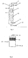
- the dominating devices of the hydration separation unit are hydration reactor 1 and hydrate decomposer 3, whose structures are respectively as follows:
- the internal upper part of hydrate decomposer 3 is equipped with wire mesh demisters 15.
- Other devices of the hydration separator include three heat exchangers 2, 4 and 5, a booster pump 6, a refrigerator which may use ammonia, Freon or propane as cryogen, not shown in the figures) and several valves, tubes and lines. All the heat exchangers are shell and tube countercurrent heat exchangers.
- the tube passes of heat exchanger 2 is for the passing of hot water with the inlet temperature of hot water between 30°C and 40°C;
- the shell passes of heat exchanger 2, as is the same with those of heat exchanger 5, is for the passing of hydrate slurry;
- the tube passes of heat exchanger 5 is for the passing of cryogens whose evaporating temperature is -3 to -5°C;
- booster pump 6 is a volume measuring pump.
- the method of the present invention makes that: a part of the gases (gas mixtures containing hydrogen) from the high pressure separator, after cooled to 1-10°C, enter into the hydration separation unit, wherein the gases (gas mixtures containing hydrogen) contact with a water-in-oil microemulsion and generate hydrates and in this way, light hydrocarbon components such as methane etc. are removed to increase the concentration of hydrogen to 96-98% (V, volume percentage) or even more.
- the gases containing concentration-increased hydrogen, i.e. gases in which the concentration of hydrogen is increased, away from the hydration separation unit are mix ed with another flow of gases to serve as the recycle hydrogen, which returns to a hydrocracking reactor through a circulating compressor.
- the concentration of the recycle hydrogen reaches 93-95% or even higher, keeping the concentration and the partial pressure of hydrogen at high levels, and leading to much less energy consumption, improvement of the hydration performance and larger economic benefits.
- the method is particularly suitable for hydrocracking unit, and can also be applied on equipments for the synthesis of ammonia and for the production of methanol with synthesized gases. The inventor contemplates that the method will pave the way for the successful separation of hydrogen and can also be extended for the separation of other light gases, such as separation of C1 and C2.
- a hydration separation unit comprising a hydration reactor 1 and a hydrate decomposer 3 was included.
- the hydration reactor 1 was constructed with the combination of a mist spray and sieve plates.
- the upper part of the reactor was the mist spray area equipped with sprayers 13 and a set of serpentine cooling pipes 9.
- the lower part of the reactor was the sieve plates area equipped with sieve plates 10.
- the internal upper part of the hydrate decomposer 3 was equipped with wire mesh demisters 15.
- a high pressure separator was connected with the inlet 11 of raw gases at the lower part of the sieve plates area of the hydration reactor via heat exchanger 4; the outlet 12 of hydrate slurry at the bottom of the hydration reactor was connected with the inlet 17 of hydrate slurry of the hydrate decomposer via heat exchanger 2; the outlet 7 of hydrogen with high concentration (rich hydrogen) at the top of the hydration reactor was connected with the recycle hydrogen compressor; the outlet 16 of water-in-oil microemulsion at the bottom of the hydrate decomposer was connected with the inlet 8 of water-in-oil microemulsion of the hydrate decomposer via heat exchanger 5 and booster pump 6; the outlet 14 at the top of the hydrate decomposer was connected with the fuel gas system.
- All the heat exchangers were shell and tube countercurrent heat exchangers.
- the tube passes of heat exchanger 2 was for the passing of hot water with the inlet temperature of hot water between 30°C and 40°C;
- the tube passes of heat exchanger 5 was for the passing of cryogens whose evaporating temperature was -3 to -5°C;
- booster pump 6 was a volume measuring pump.
- the composition of raw gases entering into the hydration separation unit was: H 2 (94 mol%)+CH 4 (4 mol%)+C 2 H 6 (2 mol%).
- the operating temperature of the hydration reactor was 1-5 °C
- the operating pressure was 18 MPa
- the water-in-oil microemulsion was prepared with 3 volumes of water solution in which the mass concentration of tetrahydrofuran is 25% by weight and 7 volumes of diesel
- the microemulsion/gas flux ratio was 1/100 (standard VN)
- the gases stay in the reactor for 15min.
- the gases contained H 2 (98 mol%)+CH 4 (1.8 mol%)+C 2 H 6 (0.2 mol%).
- the concentration of hydrogen in the mixture of concentration-increased gases and raw gases was in amount of 95%, indicating that of the gases coming from the high pressure separator, mixing of 25% which had experienced the increase of concentration in the hydration separation unit, with the remaining 75%, could yield a 95% concentration of recycle hydrogen. If passing through the hydrocracking reactor once, the concentration of the recycle hydrogen was only lowered by 1 %, the concentration of recycle hydrogen could be maintained at 95% with said method in which the 25% of the recycle hydrogen had experienced concentration-increase by hydration.
Landscapes
- Chemical & Material Sciences (AREA)
- Oil, Petroleum & Natural Gas (AREA)
- Organic Chemistry (AREA)
- Engineering & Computer Science (AREA)
- Chemical Kinetics & Catalysis (AREA)
- General Chemical & Material Sciences (AREA)
- Combustion & Propulsion (AREA)
- Inorganic Chemistry (AREA)
- Analytical Chemistry (AREA)
- Organic Low-Molecular-Weight Compounds And Preparation Thereof (AREA)
- Production Of Liquid Hydrocarbon Mixture For Refining Petroleum (AREA)
- Hydrogen, Water And Hydrids (AREA)
Claims (10)
- Appareil pour augmenter la concentration d'hydrogène recyclé dans une unité d'hydrogénation haute pression comprenant un réacteur d'hydrocraquage et un séparateur haute pression, la sortie du réacteur d'hydrocraquage étant connecté pour les fluides avec l'entrée dudit séparateur haute pression, la sortie dudit séparateur haute pression étant connecté pour les fluides avec l'entrée dudit réacteur d'hydrocraquage formant une boucle d'écoulement des fluides, caractérisé en ce que :une unité de séparation d'hydratation est pourvue sur le chemin d'écoulement des fluides depuis ledit séparateur haute pression vers le réacteur d'hydrocraquage, ladite unité de séparation d'hydratation comprenant :un réacteur d'hydratation dans lequel une microémulsion eau dans l'huile est introduite ce par quoi les composants légers des produits d'hydrocraquage sont combinés dans ladite microémulsion eau dans l'huile ; etun réducteur d'hydrates étant connecté au dit réacteur d'hydratation pour former une boucle d'écoulement des fluides et réduisant les composants légers de ladite microémulsion qui combine lesdits composants légers.
- Appareil pour augmenter la concentration d'hydrogène recyclé dans un réacteur d'hydrogénation haute pression selon la revendication 1, caractérisé en ce que ledit réacteur d'hydratation est construit avec une combinaison d'une zone de brumisation et d'une zone de plateaux cribleurs, et la partie supérieure dudit réacteur d'hydratation est la zone de brumisation qui est équipée d'un pulvérisateur pour éjecter la microémulsion eau dans l'huile et un ensemble de conduites de refroidissement ondulées, et la partie inférieure dudit réacteur d'hydratation est la zone de plateaux cribleurs équipée de couches multiples de plateaux cribleurs.
- Appareil pour augmenter la concentration d'hydrogène recyclé dans un réacteur d'hydrogénation haute pression selon la revendication 1, caractérisé en ce que la partie supérieure de l'intérieur dudit réducteur d'hydrates est équipée de capteurs de gouttes maillés métalliques.
- Appareil pour augmenter la concentration d'hydrogène recyclé dans un réacteur d'hydrogénation haute pression selon la revendication 1, caractérisé en ce que :ledit séparateur haute pression est connecté à une entrée de gaz brut au niveau de la partie inférieure de la zone de plateaux cribleurs du réacteur d'hydratation via un premier échangeur thermique ;une sortie de boue d'hydrates au niveau de la partie de fond du réacteur d'hydratation est connectée à une entrée de boue d'hydrates du réducteur d'hydrates via ledit premier échangeur thermique et un échangeur thermique secondaire ;une sortie d'hydrogène avec une concentration élevée en haut du réacteur d'hydratation est connectée à un compresseur d'hydrogène en circulation ;une sortie de microémulsion eau dans l'huile au fond du réducteur d'hydrates est connectée avec une entrée de vaporisateur de microémulsion eau dans l'huile sur la partie du dessus du réacteur d'hydratation via un troisième échangeur thermique et une pompe de surpression ; etla partie du dessus du réducteur d'hydrates est connectée à un système de gaz combustibles.
- Procédé pour augmenter la concentration d'hydrogène recyclé dans un réacteur d'hydrogénation haute pression utilisant l'appareil selon l'une quelconque des revendications 1 à 4, caractérisé en ce que le procédé comprend les étapes suivantes consistant àfaire passer une partie des mélanges gazeux qui contiennent de l'hydrogène et proviennent du séparateur haute pression dans le premier échangeur thermique et procéder à un échange thermique avec la boue d'hydrates provenant du réacteur d'hydratation de l'unité de séparation d'hydratation et, après avoir pré-refroidi à 1 - 10° C, la faire entrer dans le réacteur d'hydratation depuis la partie inférieure du réacteur d'hydratation et la faire remonter dans le réacteur d'hydratation ;établir un contact entre les mélanges gazeux contenant de l'hydrogène et la microémulsion eau dans l'huile qui descend dans le réacteur d'hydratation, ce par quoi les composants hydrocarbures légers (méthane, éthane, etc.) des mélanges gazeux contenant de l'hydrogène sont combinés en hydrates et ainsi éliminés des mélanges gazeux contenant de l'hydrogène, la chaleur générée par la réaction étant retirée par les conduites de refroidissement installées à l'intérieur du réacteur d'hydratation, dans lequel la température d'évaporation des cryogènes dans les conduites de refroidissement est de -3 à -5° C ; aprèsla réaction, la concentration de l'hydrogène dans les mélanges gazeux est augmentée, et les mélanges gazeux avec une concentration augmentée d'hydrogène quittent par le haut le réacteur d'hydratation et entrent dans le compresseur de circulation avec une autre partie des gaz de mélange qui contiennent de l'hydrogène et proviennent du séparateur haute pression ;faire quitter la microémulsion eau dans l'huile et les hydrates générés du réacteur d'hydratation par le fond de celui-ci sous la forme d'une boue d'hydrates,chauffer principalement la boue d'hydrates via ledit premier échangeur thermique par échange thermique avec les mélanges gazeux contenant de l'hydrogène provenant du séparateur haute pression,chauffer encore la boue d'hydrates via un échangeur thermique secondaire, puis la faire entrer dans le réducteur d'hydrates, etdiviser la boue d'hydrates dans le réducteur d'hydrates en un écoulement gazeux et un écoulement liquide, dans lequel l'écoulement gazeux contenant les composants légers est libéré du haut du réducteur d'hydrate et envoyé dans le système de gaz combustibles ; l'écoulement liquide contenant la microémulsion eau dans l'huile est réutilisé après avoir circulé dans la pompe de surpression et retourné dans le réacteur d'hydratation.
- Procédé pour augmenter la concentration d'hydrogène recyclé dans un réacteur d'hydrogénation haute pression selon la revendication 5, caractérisé en ce que la pression de fonctionnement du réacteur d'hydratation est la pression de gaz provenant du séparateur haute pression, et la température de fonctionnement est 1 - 10° C, la pression de fonctionnement du réducteur d'hydrates est 0,2 - 2 MPa et la température de fonctionnement est 5 - 25° C.
- Procédé pour augmenter la concentration d'hydrogène recyclé dans un réacteur d'hydrogénation haute pression selon la revendication 5, caractérisé en ce que l'écoulement de gaz entrant dans l'unité de séparation d'hydratation est présent dans une quantité de 20 % ∼ 100 % de l'écoulement de gaz total sortant du séparateur haute pression.
- Procédé pour augmenter la concentration d'hydrogène recyclé dans un réacteur d'hydrogénation haute pression selon la revendication 5, caractérisé en ce que le rapport volumétrique de la phase huileuse et de la phase aqueuse dans la microémulsion eau dans l'huile varie de 1 : 1 à 5 : 1.
- Procédé pour augmenter la concentration d'hydrogène recyclé dans un réacteur d'hydrogénation haute pression selon la revendication 5, caractérisé en ce que la phase huileuse dans ladite microémulsion eau dans l'huile est sélectionnée parmi le groupe constitué de diésel, kérosène et alcanes non solubles dans l'eau.
- Procédé pour augmenter la concentration d'hydrogène recyclé dans un réacteur d'hydrogénation haute pression selon la revendication 5, caractérisé en ce que 10 % - 40 % de tétrahydrofurane est ajouté à la phase aqueuse en fonction de la concentration de masse ou 20 % - 50 % de cyclopentane est ajouté à la phase huileuse en fonction de la concentration de masse avant de mélanger la phase aqueuse et la phase huileuse pour préparer la microémulsion eau dans l'huile.
Applications Claiming Priority (1)
| Application Number | Priority Date | Filing Date | Title |
|---|---|---|---|
| CN2006101500857A CN101168685B (zh) | 2006-10-26 | 2006-10-26 | 一种提高高压加氢反应装置循环氢浓度的设备及工艺 |
Publications (2)
| Publication Number | Publication Date |
|---|---|
| EP1930397A1 EP1930397A1 (fr) | 2008-06-11 |
| EP1930397B1 true EP1930397B1 (fr) | 2009-02-11 |
Family
ID=39273291
Family Applications (1)
| Application Number | Title | Priority Date | Filing Date |
|---|---|---|---|
| EP07020668A Active EP1930397B1 (fr) | 2006-10-26 | 2007-10-23 | Appareil et procédé d'augmentation de la concentration d'hydrogène de recyclage dans un réacteur d'hydrogénation à haute pression |
Country Status (5)
| Country | Link |
|---|---|
| US (1) | US7785547B2 (fr) |
| EP (1) | EP1930397B1 (fr) |
| CN (1) | CN101168685B (fr) |
| DE (1) | DE602007000539D1 (fr) |
| DK (1) | DK1930397T3 (fr) |
Families Citing this family (10)
| Publication number | Priority date | Publication date | Assignee | Title |
|---|---|---|---|---|
| FR2938522B1 (fr) * | 2008-11-20 | 2010-12-17 | Inst Francais Du Petrole | Procede de production d'hydrogene avec captation totale du co2 et recyclage du methane non converti |
| CN104422249B (zh) * | 2013-08-23 | 2016-11-02 | 中国石油天然气股份有限公司 | 一种用于催化汽油加氢催化剂干燥的方法 |
| CN104877707B (zh) * | 2015-05-07 | 2017-12-15 | 北京中科诚毅科技发展有限公司 | 一种多重优化的加氢系列方法及其设计方法和用途 |
| CN106433759A (zh) * | 2016-08-29 | 2017-02-22 | 广饶科力达石化科技有限公司 | 一种润滑油加氢装置 |
| CN107913645A (zh) * | 2016-10-11 | 2018-04-17 | 中国石油化工股份有限公司 | 一种可实现能量回收的加氢反应进料系统 |
| CN112705120B (zh) * | 2019-10-25 | 2022-07-08 | 中国石油化工股份有限公司 | 一种重质油加工装置及加工方法 |
| CN114130162A (zh) * | 2020-09-03 | 2022-03-04 | 中国科学院大连化学物理研究所 | 一种基于笼型水合物原理的氟利昂气体捕集与纯化方法 |
| CN114604828A (zh) * | 2022-03-07 | 2022-06-10 | 大连汉诺工程技术有限公司 | 一种水合物法氢气提浓装置及工艺 |
| CN114768511B (zh) * | 2022-04-30 | 2023-04-21 | 福建德尔科技股份有限公司 | 一种用于电子级三氟甲烷生产的尾气吸收装置 |
| CN115417577B (zh) * | 2022-05-13 | 2023-07-18 | 大连理工大学 | 一种基于水合物法常压连续污泥调质系统及方法 |
Family Cites Families (8)
| Publication number | Priority date | Publication date | Assignee | Title |
|---|---|---|---|---|
| EP0061259A1 (fr) | 1981-03-12 | 1982-09-29 | Monsanto Company | Procédé d'hydrocraquage à efficacité élevée de l'utilisation d'hydrogène |
| US4553981A (en) * | 1984-02-07 | 1985-11-19 | Union Carbide Corporation | Enhanced hydrogen recovery from effluent gas streams |
| US4842622A (en) * | 1988-03-31 | 1989-06-27 | Wamsley Jr Robert H | Gas/liquid/solids separator |
| US5082551A (en) | 1988-08-25 | 1992-01-21 | Chevron Research And Technology Company | Hydroconversion effluent separation process |
| US5434330A (en) * | 1993-06-23 | 1995-07-18 | Hnatow; Miguel A. | Process and apparatus for separation of constituents of gases using gas hydrates |
| CN1053691C (zh) * | 1996-07-25 | 2000-06-21 | 刘世凯 | 一种加氢工艺 |
| US7193123B2 (en) * | 2004-05-21 | 2007-03-20 | Exxonmobil Chemical Patents Inc. | Process and apparatus for cracking hydrocarbon feedstock containing resid to improve vapor yield from vapor/liquid separation |
| CN100475933C (zh) | 2004-06-11 | 2009-04-08 | 中国石油天然气股份有限公司 | 用于分离回收炼厂干气中的氢气、乙烯、乙烷或分离乙烯裂解气的组合工艺 |
-
2006
- 2006-10-26 CN CN2006101500857A patent/CN101168685B/zh active Active
-
2007
- 2007-10-23 DK DK07020668T patent/DK1930397T3/da active
- 2007-10-23 EP EP07020668A patent/EP1930397B1/fr active Active
- 2007-10-23 DE DE602007000539T patent/DE602007000539D1/de active Active
- 2007-10-23 US US11/977,426 patent/US7785547B2/en active Active
Also Published As
| Publication number | Publication date |
|---|---|
| US20080112862A1 (en) | 2008-05-15 |
| CN101168685B (zh) | 2010-11-03 |
| US7785547B2 (en) | 2010-08-31 |
| CN101168685A (zh) | 2008-04-30 |
| DK1930397T3 (da) | 2009-05-04 |
| EP1930397A1 (fr) | 2008-06-11 |
| DE602007000539D1 (de) | 2009-03-26 |
Similar Documents
| Publication | Publication Date | Title |
|---|---|---|
| US7785547B2 (en) | Apparatus and method for increasing the concentration of recycled hydrogen in a high pressure hydrogenation reactor | |
| CN100519406C (zh) | 从合成气中除去氮、甲烷和氩用低△p净化器 | |
| CN103232321B (zh) | 一种甲醇合成工艺 | |
| CA1233109A (fr) | Methode et dispositif de production de co pur | |
| CN101173190B (zh) | 费托合成油的加工流程 | |
| CN101108978B (zh) | 碳氢化合物气体处理方法与装置 | |
| CN101979476B (zh) | 一种煤制合成气进行甲烷化合成天然气的工艺 | |
| CN106288653A (zh) | 一种单塔低温精馏回收氩气的装置及纯化回收氩气的方法 | |
| CN111748366A (zh) | 一种二氧化碳加氢直接制汽油馏分烃的装置及方法 | |
| CN105001900A (zh) | 一种焦炉煤气经甲醇合成汽油的工艺 | |
| CN103214009A (zh) | 一种合成氨脱碳工艺 | |
| CN101244970A (zh) | 乙醇制备乙烯的生产装置及工艺 | |
| CN102502901B (zh) | 一种配套co变换装置使用的冷凝液汽提方法 | |
| CN112473572A (zh) | 水合反应装置 | |
| CN117720397B (zh) | 一种二氧化碳催化加氢制甲醇的工艺和装置 | |
| TWI652257B (zh) | 藉由分離技術處理二甲醚反應器之產物流的方法 | |
| JP3923766B2 (ja) | 水素製造装置 | |
| CN202519029U (zh) | 单晶硅生产中氩气回收纯化装置 | |
| CN104709877A (zh) | 一种回收合成氨驰放气中氮气和氢气装置及方法 | |
| CN103542693A (zh) | 大型乙烯装置的乙烯深冷分离方法 | |
| US3388968A (en) | Ammonia synthesis feed and recycle loop | |
| CN111018671B (zh) | 一种草酸二甲酯加氢合成乙二醇的系统及其制备方法 | |
| CN221309948U (zh) | 一种天然气脱酸橇 | |
| CN218357432U (zh) | 丙二醇二次精馏提纯装置 | |
| CN101550065A (zh) | 一种节能节水型高低压双塔甲醇精馏二甲醚生产工艺 |
Legal Events
| Date | Code | Title | Description |
|---|---|---|---|
| PUAI | Public reference made under article 153(3) epc to a published international application that has entered the european phase |
Free format text: ORIGINAL CODE: 0009012 |
|
| 17P | Request for examination filed |
Effective date: 20071023 |
|
| AK | Designated contracting states |
Kind code of ref document: A1 Designated state(s): AT BE BG CH CY CZ DE DK EE ES FI FR GB GR HU IE IS IT LI LT LU LV MC MT NL PL PT RO SE SI SK TR |
|
| AX | Request for extension of the european patent |
Extension state: AL BA HR MK RS |
|
| 17Q | First examination report despatched |
Effective date: 20080814 |
|
| GRAP | Despatch of communication of intention to grant a patent |
Free format text: ORIGINAL CODE: EPIDOSNIGR1 |
|
| GRAS | Grant fee paid |
Free format text: ORIGINAL CODE: EPIDOSNIGR3 |
|
| GRAA | (expected) grant |
Free format text: ORIGINAL CODE: 0009210 |
|
| RIN1 | Information on inventor provided before grant (corrected) |
Inventor name: WANG, XIULIN Inventor name: GUO, XUQIANG Inventor name: YAN, LIJUN Inventor name: MA, AN Inventor name: CHEN, GUANGJIN Inventor name: SUN, CHANGYU |
|
| RAP1 | Party data changed (applicant data changed or rights of an application transferred) |
Owner name: CHINA UNIVERSITY OF PETROLEUM BEIJING Owner name: PETROCHINA COMPANY LIMITED |
|
| AK | Designated contracting states |
Kind code of ref document: B1 Designated state(s): DE DK FR GB |
|
| REG | Reference to a national code |
Ref country code: GB Ref legal event code: FG4D |
|
| AKX | Designation fees paid |
Designated state(s): DE DK FR GB |
|
| REF | Corresponds to: |
Ref document number: 602007000539 Country of ref document: DE Date of ref document: 20090326 Kind code of ref document: P |
|
| REG | Reference to a national code |
Ref country code: DK Ref legal event code: T3 |
|
| PLBE | No opposition filed within time limit |
Free format text: ORIGINAL CODE: 0009261 |
|
| STAA | Information on the status of an ep patent application or granted ep patent |
Free format text: STATUS: NO OPPOSITION FILED WITHIN TIME LIMIT |
|
| 26N | No opposition filed |
Effective date: 20091112 |
|
| REG | Reference to a national code |
Ref country code: FR Ref legal event code: PLFP Year of fee payment: 9 |
|
| REG | Reference to a national code |
Ref country code: FR Ref legal event code: PLFP Year of fee payment: 10 |
|
| REG | Reference to a national code |
Ref country code: FR Ref legal event code: PLFP Year of fee payment: 11 |
|
| REG | Reference to a national code |
Ref country code: FR Ref legal event code: PLFP Year of fee payment: 12 |
|
| PGFP | Annual fee paid to national office [announced via postgrant information from national office to epo] |
Ref country code: GB Payment date: 20250911 Year of fee payment: 19 |
|
| PGFP | Annual fee paid to national office [announced via postgrant information from national office to epo] |
Ref country code: FR Payment date: 20250908 Year of fee payment: 19 |
|
| PGFP | Annual fee paid to national office [announced via postgrant information from national office to epo] |
Ref country code: DE Payment date: 20250910 Year of fee payment: 19 |
|
| PGFP | Annual fee paid to national office [announced via postgrant information from national office to epo] |
Ref country code: DK Payment date: 20251014 Year of fee payment: 19 |