EP1930197B1 - Montage eines Wärmetauschers - Google Patents
Montage eines Wärmetauschers Download PDFInfo
- Publication number
- EP1930197B1 EP1930197B1 EP07121507A EP07121507A EP1930197B1 EP 1930197 B1 EP1930197 B1 EP 1930197B1 EP 07121507 A EP07121507 A EP 07121507A EP 07121507 A EP07121507 A EP 07121507A EP 1930197 B1 EP1930197 B1 EP 1930197B1
- Authority
- EP
- European Patent Office
- Prior art keywords
- cooler
- radiator
- cooler assembly
- assembly
- groove
- Prior art date
- Legal status (The legal status is an assumption and is not a legal conclusion. Google has not performed a legal analysis and makes no representation as to the accuracy of the status listed.)
- Active
Links
- 230000001419 dependent effect Effects 0.000 claims 1
- 239000003570 air Substances 0.000 description 4
- 230000005540 biological transmission Effects 0.000 description 3
- 238000004140 cleaning Methods 0.000 description 3
- 238000003915 air pollution Methods 0.000 description 1
- 239000012080 ambient air Substances 0.000 description 1
- 238000010276 construction Methods 0.000 description 1
- 239000002826 coolant Substances 0.000 description 1
- 238000001816 cooling Methods 0.000 description 1
- 239000000498 cooling water Substances 0.000 description 1
- 230000005484 gravity Effects 0.000 description 1
- 230000003993 interaction Effects 0.000 description 1
- 230000000717 retained effect Effects 0.000 description 1
- 238000005096 rolling process Methods 0.000 description 1
- 238000000926 separation method Methods 0.000 description 1
Images


Classifications
-
- B—PERFORMING OPERATIONS; TRANSPORTING
- B60—VEHICLES IN GENERAL
- B60K—ARRANGEMENT OR MOUNTING OF PROPULSION UNITS OR OF TRANSMISSIONS IN VEHICLES; ARRANGEMENT OR MOUNTING OF PLURAL DIVERSE PRIME-MOVERS IN VEHICLES; AUXILIARY DRIVES FOR VEHICLES; INSTRUMENTATION OR DASHBOARDS FOR VEHICLES; ARRANGEMENTS IN CONNECTION WITH COOLING, AIR INTAKE, GAS EXHAUST OR FUEL SUPPLY OF PROPULSION UNITS IN VEHICLES
- B60K11/00—Arrangement in connection with cooling of propulsion units
- B60K11/02—Arrangement in connection with cooling of propulsion units with liquid cooling
- B60K11/04—Arrangement or mounting of radiators, radiator shutters, or radiator blinds
-
- F—MECHANICAL ENGINEERING; LIGHTING; HEATING; WEAPONS; BLASTING
- F01—MACHINES OR ENGINES IN GENERAL; ENGINE PLANTS IN GENERAL; STEAM ENGINES
- F01P—COOLING OF MACHINES OR ENGINES IN GENERAL; COOLING OF INTERNAL-COMBUSTION ENGINES
- F01P3/00—Liquid cooling
- F01P3/18—Arrangements or mounting of liquid-to-air heat-exchangers
-
- F—MECHANICAL ENGINEERING; LIGHTING; HEATING; WEAPONS; BLASTING
- F02—COMBUSTION ENGINES; HOT-GAS OR COMBUSTION-PRODUCT ENGINE PLANTS
- F02B—INTERNAL-COMBUSTION PISTON ENGINES; COMBUSTION ENGINES IN GENERAL
- F02B29/00—Engines characterised by provision for charging or scavenging not provided for in groups F02B25/00, F02B27/00 or F02B33/00 - F02B39/00; Details thereof
- F02B29/04—Cooling of air intake supply
- F02B29/0406—Layout of the intake air cooling or coolant circuit
- F02B29/0412—Multiple heat exchangers arranged in parallel or in series
-
- F—MECHANICAL ENGINEERING; LIGHTING; HEATING; WEAPONS; BLASTING
- F02—COMBUSTION ENGINES; HOT-GAS OR COMBUSTION-PRODUCT ENGINE PLANTS
- F02B—INTERNAL-COMBUSTION PISTON ENGINES; COMBUSTION ENGINES IN GENERAL
- F02B29/00—Engines characterised by provision for charging or scavenging not provided for in groups F02B25/00, F02B27/00 or F02B33/00 - F02B39/00; Details thereof
- F02B29/04—Cooling of air intake supply
- F02B29/045—Constructional details of the heat exchangers, e.g. pipes, plates, ribs, insulation, materials, or manufacturing and assembly
- F02B29/0456—Air cooled heat exchangers
-
- F—MECHANICAL ENGINEERING; LIGHTING; HEATING; WEAPONS; BLASTING
- F28—HEAT EXCHANGE IN GENERAL
- F28D—HEAT-EXCHANGE APPARATUS, NOT PROVIDED FOR IN ANOTHER SUBCLASS, IN WHICH THE HEAT-EXCHANGE MEDIA DO NOT COME INTO DIRECT CONTACT
- F28D1/00—Heat-exchange apparatus having stationary conduit assemblies for one heat-exchange medium only, the media being in contact with different sides of the conduit wall, in which the other heat-exchange medium is a large body of fluid, e.g. domestic or motor car radiators
- F28D1/02—Heat-exchange apparatus having stationary conduit assemblies for one heat-exchange medium only, the media being in contact with different sides of the conduit wall, in which the other heat-exchange medium is a large body of fluid, e.g. domestic or motor car radiators with heat-exchange conduits immersed in the body of fluid
- F28D1/04—Heat-exchange apparatus having stationary conduit assemblies for one heat-exchange medium only, the media being in contact with different sides of the conduit wall, in which the other heat-exchange medium is a large body of fluid, e.g. domestic or motor car radiators with heat-exchange conduits immersed in the body of fluid with tubular conduits
- F28D1/0408—Multi-circuit heat exchangers, e.g. integrating different heat exchange sections in the same unit or heat exchangers for more than two fluids
-
- B—PERFORMING OPERATIONS; TRANSPORTING
- B60—VEHICLES IN GENERAL
- B60Y—INDEXING SCHEME RELATING TO ASPECTS CROSS-CUTTING VEHICLE TECHNOLOGY
- B60Y2200/00—Type of vehicle
- B60Y2200/20—Off-Road Vehicles
- B60Y2200/22—Agricultural vehicles
- B60Y2200/221—Tractors
Definitions
- the present invention relates to the mounting of heat exchangers in agricultural vehicles, in particular to a cooler block for use in tractors.
- Tractors have several heat exchangers which form part of different cooling systems.
- a heat exchanger normally termed a radiator
- a second heat exchanger is used to cool oil circulating in the transmission system and a further heat exchanger is used to cool the engine charge air.
- the latter two heat exchangers are commonly referred to as coolers. All three of these heat exchangers, form a cooler block located at the front of the tractor so that a single electric or engine driven radiator fan can suck ambient air through all of them.
- the cooler block contains at least a front cooler, a central cooler, and a rear cooler.
- the rear cooler is attached at a fixed position on the frame of the agricultural tractor and the central cooler can be moved away from the rear cooler while the front cooler can also be moved away from the central cooler.
- the front cooler is suspended so that it can move sufficiently upwards and, if necessary, also forwards, that the central cooler can be swung away from the rear cooler unhindered to the side at about a right angle.
- FIG. 1 of the accompanying drawings shows a known cooler block in which the transmission oil cooler and the air charge cooler together form a cooler assembly 12 that is mounted for pivotal movement relative to a radiator 10, to allow the two to be separated for cleaning.
- the cooler assembly 12 On each side of the radiator 10, the cooler assembly 12 is supported by means of a spigot 14 that rests in a groove 16 in a top bracket 18 mounted on the radiator 10.
- a lower bracket 20 is firmly secured to the cooler assembly 12 and it is formed with a groove 22 in the form of a circular arc centred on the spigot 14 which receives a pin 24 projecting from the side of the radiator 10. This mounting allows the cooler assembly to pivot about the spigot 14 through an angle determined by the length of the groove 22 but not to be lifted off the bracket 18.
- This mounting has certain disadvantages, one being that the cooler assembly at its upper end can only pivot about the spigot 14, which does not create much separation between the cooler assembly 12 and the radiator 10 for cleaning purposes. Furthermore, when the lower end of the cooler assembly 12 is pivoted away from the radiator, stays or gas struts are needed to maintain it in the separated position. These gas struts may assist in the movement of the cooler assembly in one direction but they interfere with movement in the opposite direction. Furthermore, they can hinder access to the space created between the cooler assembly and the radiator for cleaning purposes.
- JP 2000 212995 A discloses a cooler block for an agricultural tractor comprising a cooler assembly mounted on a radiator and coupled to the radiator by means of upper and lower linkages to allow the cooler assembly to be moved between a first position in which the cooler assembly lies parallel to the radiator and a second position in which the cooler assembly is inclined relative to the radiator, wherein the cooler assembly is pivotable about a pivot in the upper linkage that is itself movable relative to the radiator, and the lower linkage is such that the entire cooler assembly rises and the pivot of the upper linkage moves away from the radiator as the cooler assembly is pivoted from the first to the second position.
- the present invention seeks therefore to improve the mounting of a cooler assembly on a radiator in a cooler block so that the cooler assembly can be retained in a separated position without the use of stays.
- the upper linkage comprises a bracket rigidly secured to the radiator and having a groove for receiving a spigot which projects from the cooler assembly and serves as the pivot, and wherein the lower linkage is such that the spigot slides along the groove to raise the upper end of the cooler assembly and to move it away from the radiator as the cooler assembly pivots about the spigot.
- the detent for retaining the cooler assembly in the second position may suitably be formed by a depression in the groove of the upper linkage.
- the spigot of the upper linkage is advantageously fitted with an anti-friction bearing, i.e. a bearing with rolling bearing elements such as balls, needles or rollers.
- the pin engaging in the groove of the bracket of the lower linkage may be fitted with an anti-friction bearing to ease movement of the cooler assembly.
- a depression may be formed in the groove of the bracket secured to the cooler assembly to serve as a detent for retaining the cooler assembly in the second position.
- a catch is provided to retain the cooler assembly in the first position relative to the radiator.
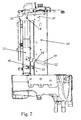
- brackets 18' and 20' are different from the corresponding bracket 18 and 20 used in the prior art, in particular the shape of the grooves 16' and 22' has been significantly modified.
- the shape of the groove 16 is unimportant because after it has dropped into it, the spigot 14 never moves from the bottom of the groove 16. Furthermore, as the groove 22 is substantially an arc centred on the spigot 14, the bracket 20 serves only to limit the angle through which it is possible to swing the cooler assembly 12 and it does not support any part of the weight of the cooler assembly nor does it hold the cooler assembly 12 stationary in any position.
- the groove 22' in the embodiment of the invention shown in Figures 2 and 3 is not equidistant from the spigot 14' at all points along its length.
- the cooler assembly does not only pivot about the spigot 14' but it also rises and the spigot 14' is forced to move along the groove 16'.
- the shape of the groove 14' is not a straight line but is an upwardly convex curve which is additionally formed at its end with a depression 30.
- first position of the cooler assembly 12 shown in Figure 2 most of its weight is supported by the spigot 14' abutting the end of the groove 16'.
- second position shown in Figure 3
- substantially all its weight is initially taken up by the pin 24' which rides in the grooves 22'.
- the spigot 14' reaches the horizontal section of the groove 16', it again supports the weight of the cooler assembly 12.
- the weight of the cooler assembly 12 acts to maintain the spigot 14' in the depression 30 and the latter therefore acts as a detent preventing the cooler assembly from returning under the force of gravity to its first position.
- the interaction between the pin 24' and the groove 22' ensures that the cooler assembly remains pivoted away from the radiator 10 as shown in Figure 3 .
- a depression can be formed in the groove 22' to act in a similar manner as a detent, in addition to or instead of the depression in the groove 16'.
- the spigot 14 did not move along the groove 16 and friction between them did pose a problem.
- the pin 24 did not support the weight of the cooler assembly 12 and friction between it and the groove 22 did not pose a problem. Neither of these conditions holds true in the present invention and friction at either of the grooves 16' and 22' would make it more difficult to move the cooler assembly 12.
- the spigot 14' and the pin 24' are modified by being fitted with a roller bearing to reduce the friction between them and the grooves in which they slide.
Landscapes
- Engineering & Computer Science (AREA)
- Mechanical Engineering (AREA)
- Chemical & Material Sciences (AREA)
- Combustion & Propulsion (AREA)
- General Engineering & Computer Science (AREA)
- Physics & Mathematics (AREA)
- Thermal Sciences (AREA)
- Transportation (AREA)
- Cooling, Air Intake And Gas Exhaust, And Fuel Tank Arrangements In Propulsion Units (AREA)
- Compression-Type Refrigeration Machines With Reversible Cycles (AREA)
- Filling Or Discharging Of Gas Storage Vessels (AREA)
Claims (8)
- Kühler-Block für einen landwirtschaftlichen Traktor, mit einer Kühlvorrichtungs-Baugruppe (12), die auf einem Kühler (10) befestigt und mit dem Kühler (10) über obere und untere Gestänge verbunden ist, um eine Bewegung der Kühlvorrichtungs-Baugruppe (12) zwischen einer ersten Position, in der die Kühlvorrichtungs-Baugruppe (12) parallel zu dem Kühler (10) liegt, und einer zweiten Position zu ermöglichen, in der die Kühlvorrichtungs-Baugruppe (12) gegenüber dem Kühler (10) geneigt ist, wobei die Kühlvorrichtungs-Baugruppe (12) um einen Schwenkpunkt (14') in dem oberen Gestänge verschwenkbar ist, das seinerseits gegenüber dem Kühler (10) beweglich ist, und wobei das untere Gestänge derart ist, dass die gesamte Kühlvorrichtungs-Baugruppe (12) angehoben wird und der Schwenkpunkt (14') des oberen Gestänges sich von dem Kühler fortbewegt, wenn die Kühlvorrichtungs-Baugruppe (12) von der ersten auf die zweite Position verschwenkt wird, dadurch gekennzeichnet, dass das untere Gestänge einen Haltebügel (20') umfasst, der starr an der Kühlvorrichtungs-Baugruppe (12) befestigt ist und eine Nut (22') aufweist, die einen Bolzen (24)') aufnimmt, der von dem Kühler (10) vorspringt, wobei die Nut (22') in einer derartigen Weise geneigt ist, dass sie das untere Ende der Kühlvorrichtungs-Baugruppe (12) von dem Kühler (10) fortbewegt, wenn die Kühlvorrichtungs-Baugruppe (12) um den Schwenkpunkt (14') des oberen Gestänges verschwenkt wird.
- Kühler-Block nach Anspruch 1, bei dem das obere Gestänge einen Haltebügel (18') umfasst, der starr an dem Kühler (10) befestigt ist und eine Nut (16') zur Aufnahme eines Zapfens (14') aufweist, der von der Kühlvorrichtungs-Baugruppe (12) vorspringt und als der Schwenkpunkt dient, und wobei das untere Gestänge derart ausgebildet ist, dass der Zapfen (14') entlang der Nut (22') gleitet, um das obere Ende der Kühlvorrichtungs-Baugruppe (12) anzuheben und es von dem Kühler (10) fortzubewegen, wenn die Kühlvorrichtungs-Baugruppe (12) um den Zapfen (14') verschwenkt wird.
- Kühler-Block nach Anspruch 2, bei dem der Zapfen (14') des oberen Gestänges mit einer Reibung mindernden Lagerung versehen ist.
- Kühler-Block nach einem der vorhergehenden Ansprüche, bei dem der Bolzen (24'), der in der Nut (22') des Haltebügels (20') des unteren Gestänges in Eingriff steht, mit einer Reibung mindernden Lagerung versehen ist.
- Kühler-Block nach Anspruch 2 und einem davon abhängigen Anspruch, bei dem eine Vertiefung (30) in der Nut (16') des Haltebügels (18') ausgebildet ist, der an der Kühlvorrichtungs-Baugruppe (12) befestigt ist, um als eine Raste zum Festhalten der Kühlvorrichtungs-Baugruppe (12) in der zweiten Position zu dienen.
- Kühler-Block (12) nach einem der vorhergehenden Ansprüche, bei dem ein Riegel (40, 42) zum Festhalten der Kühlvorrichtungs-Baugruppe (12) in der ersten Position gegenüber dem Kühler vorgesehen ist.
- Kühler-Block nach einem der vorhergehenden Ansprüche, bei dem eine Raste in zumindest eines der zwei Gestänge eingefügt ist, um die Kühlerbaugruppe (12) in der zweiten Position zu halten.
- Kühler-Block nach Anspruch 7, bei dem die Raste zum Festhalten der Kühlvorrichtungs-Baugruppe (12) in der zweiten Position eine Vertiefung in der Nut (16') des oberen Gestänges umfasst.
Applications Claiming Priority (1)
| Application Number | Priority Date | Filing Date | Title |
|---|---|---|---|
| GB0624198A GB2444505A (en) | 2006-12-04 | 2006-12-04 | Heat exchanger mounting |
Publications (2)
| Publication Number | Publication Date |
|---|---|
| EP1930197A1 EP1930197A1 (de) | 2008-06-11 |
| EP1930197B1 true EP1930197B1 (de) | 2010-11-17 |
Family
ID=37671828
Family Applications (1)
| Application Number | Title | Priority Date | Filing Date |
|---|---|---|---|
| EP07121507A Active EP1930197B1 (de) | 2006-12-04 | 2007-11-26 | Montage eines Wärmetauschers |
Country Status (5)
| Country | Link |
|---|---|
| US (1) | US8096347B2 (de) |
| EP (1) | EP1930197B1 (de) |
| AT (1) | ATE488395T1 (de) |
| DE (1) | DE602007010573D1 (de) |
| GB (1) | GB2444505A (de) |
Families Citing this family (18)
| Publication number | Priority date | Publication date | Assignee | Title |
|---|---|---|---|---|
| GB0526621D0 (en) * | 2005-12-30 | 2006-02-08 | Agco Sa | Cooler installation |
| FR2914618B1 (fr) * | 2007-04-03 | 2009-09-18 | Renault Sas | Procede de montage d'un element de soubassement transversal et d'une face avant technique |
| FR2922823B1 (fr) * | 2007-10-25 | 2009-12-18 | Renault Sas | Agencement pour le montage d'un echangeur thermique sur un element de structure vertical formant une face avant technique de vehicule automobile. |
| FR2930224B1 (fr) * | 2008-04-22 | 2010-08-13 | Renault Sas | Dispositif de guidage d'air d'une structure de face avant de vehicule. |
| DE102008040908A1 (de) | 2008-07-31 | 2010-02-11 | Deere & Company, Moline | Kühleranordnung für ein Fahrzeugkühlsystem |
| JP5184407B2 (ja) * | 2009-03-11 | 2013-04-17 | 株式会社クボタ | 作業機 |
| US8440913B2 (en) * | 2009-04-24 | 2013-05-14 | Abb Technology Ag | Breaker with improved shipping configuration |
| US20120103712A1 (en) * | 2010-11-03 | 2012-05-03 | Caterpillar Inc. | Skid steer machine having pivotably mounted cooling system and non-metallic vibration isolator |
| US8544584B2 (en) * | 2010-12-24 | 2013-10-01 | Komatsu Ltd. | Construction vehicle |
| DE102011053500B4 (de) * | 2011-09-12 | 2022-02-03 | Dr. Ing. H.C. F. Porsche Aktiengesellschaft | Kühleinrichtung für ein Kraftfahrzeug mit einem ausfahrbarem Heckspoiler und einem Ladeluftkühler |
| US20140125070A1 (en) * | 2012-11-08 | 2014-05-08 | Caterpillar Sarl | Cooling package latch mechanism |
| KR102200379B1 (ko) * | 2013-12-10 | 2021-01-08 | 엘지전자 주식회사 | 제습기 |
| CN104949214B (zh) | 2014-03-31 | 2018-01-05 | Lg电子株式会社 | 除湿机 |
| JP6415890B2 (ja) * | 2014-08-04 | 2018-10-31 | 株式会社クボタ | 作業車 |
| US9752302B2 (en) | 2014-09-30 | 2017-09-05 | Kubota Corporation | Working machine |
| JP6286338B2 (ja) * | 2014-09-30 | 2018-02-28 | 株式会社クボタ | 作業機 |
| JP6383234B2 (ja) * | 2014-09-30 | 2018-08-29 | 株式会社クボタ | 作業機 |
| US10400423B1 (en) * | 2018-10-04 | 2019-09-03 | Caterpillar Inc. | Radiator guard and method of making |
Family Cites Families (9)
| Publication number | Priority date | Publication date | Assignee | Title |
|---|---|---|---|---|
| US2626066A (en) * | 1947-09-29 | 1953-01-20 | Rasmussen Robert | Alternate tipping valve |
| US4696361A (en) * | 1984-03-23 | 1987-09-29 | Owatonna Manufacturing Company | Swing-up radiator and oil cooler assembly |
| JP3236764B2 (ja) * | 1995-09-21 | 2001-12-10 | 新キャタピラー三菱株式会社 | 熱交換装置 |
| EP0947780B1 (de) * | 1998-04-01 | 2004-01-07 | KERMI GmbH | Kraftarme Heiz- bzw. Kühlkörperschwenkvorrichtung |
| JP2000212995A (ja) | 1999-01-26 | 2000-08-02 | Furukawa Co Ltd | 建設車両のオイルク―ラ―開閉機構 |
| ATE348252T1 (de) * | 1999-11-05 | 2007-01-15 | Cnh Oesterreich Gmbh | Kraftfahrzeug mit einem ölkühler |
| JP3903136B2 (ja) * | 2001-11-05 | 2007-04-11 | 株式会社小松製作所 | 建設機械の冷却装置 |
| DE10206551B4 (de) * | 2002-02-16 | 2008-09-25 | CNH Österreich GmbH | Kühleranordnung für Traktoren |
| DE102005014614A1 (de) * | 2005-03-31 | 2006-10-05 | Deere & Company, Moline | Kühleranordnung |
-
2006
- 2006-12-04 GB GB0624198A patent/GB2444505A/en not_active Withdrawn
-
2007
- 2007-11-26 DE DE602007010573T patent/DE602007010573D1/de active Active
- 2007-11-26 EP EP07121507A patent/EP1930197B1/de active Active
- 2007-11-26 AT AT07121507T patent/ATE488395T1/de not_active IP Right Cessation
- 2007-11-30 US US11/947,925 patent/US8096347B2/en active Active
Also Published As
| Publication number | Publication date |
|---|---|
| US20080283214A1 (en) | 2008-11-20 |
| ATE488395T1 (de) | 2010-12-15 |
| US8096347B2 (en) | 2012-01-17 |
| DE602007010573D1 (de) | 2010-12-30 |
| GB2444505A (en) | 2008-06-11 |
| EP1930197A1 (de) | 2008-06-11 |
| GB0624198D0 (en) | 2007-01-10 |
Similar Documents
| Publication | Publication Date | Title |
|---|---|---|
| EP1930197B1 (de) | Montage eines Wärmetauschers | |
| US20250026620A1 (en) | Low profile compact tool carriers | |
| AU2009202087B8 (en) | Mast construction for a lift truck | |
| US9783247B2 (en) | Aerodynamic control system for vehicles | |
| US7398847B2 (en) | Radiator arrangement | |
| US8070170B2 (en) | Tilt device for a material handling machine | |
| CN105501128A (zh) | 用于接近升降车辆的设备 | |
| KR20140011284A (ko) | 공기 안내 장치 | |
| US2912057A (en) | Motor vehicle tiltable cab and radiator construction | |
| WO2006037841A1 (en) | Method and assembly for shifting the fork cradle of a forklift truck laterally and for tilting it longitudinally | |
| WO2013059243A1 (en) | Maximizing scissor lift breakover angle with fixed pothole protection | |
| US9915396B2 (en) | Column-levelling system | |
| GB2485918A (en) | Post driver with slidable positioning means | |
| RS59439B1 (sr) | Vozilo za rukovanje | |
| EP2399789A1 (de) | Arbeitslastigkeitsstabilisierer und Beladungsausgleichsvorrichtung für Landwirtschafts- und Pflanzenzüchtungsmaschinen sowie Arbeitsfahrzeug, insbesondere für Pflanzenzüchtungsarbeiten, mit solch einer Stabilisierungsvorrichtung | |
| JP6383234B2 (ja) | 作業機 | |
| EP2295366A1 (de) | Hubmast für Gabelstapler | |
| US20230373770A1 (en) | Front scanner level for a material handling vehicle | |
| JP2017210140A (ja) | 作業車の走行装置 | |
| JP7246088B2 (ja) | 作業機 | |
| KR102746067B1 (ko) | 수전 작업기 | |
| SE523505C2 (sv) | Anordning vid motviktstruckar | |
| JPS58212597A (ja) | フオ−クリフトのサイドシフト装置 | |
| JPH0591815A (ja) | 作業車輌のキヤビン | |
| JP2007244333A (ja) | 移植機 |
Legal Events
| Date | Code | Title | Description |
|---|---|---|---|
| PUAI | Public reference made under article 153(3) epc to a published international application that has entered the european phase |
Free format text: ORIGINAL CODE: 0009012 |
|
| AK | Designated contracting states |
Kind code of ref document: A1 Designated state(s): AT BE BG CH CY CZ DE DK EE ES FI FR GB GR HU IE IS IT LI LT LU LV MC MT NL PL PT RO SE SI SK TR |
|
| AX | Request for extension of the european patent |
Extension state: AL BA HR MK RS |
|
| 17P | Request for examination filed |
Effective date: 20081211 |
|
| AKX | Designation fees paid |
Designated state(s): AT BE BG CH CY CZ DE DK EE ES FI FR GB GR HU IE IS IT LI LT LU LV MC MT NL PL PT RO SE SI SK TR |
|
| 17Q | First examination report despatched |
Effective date: 20090123 |
|
| GRAP | Despatch of communication of intention to grant a patent |
Free format text: ORIGINAL CODE: EPIDOSNIGR1 |
|
| RTI1 | Title (correction) |
Free format text: HEAT EXCHANGER MOUNTING |
|
| GRAS | Grant fee paid |
Free format text: ORIGINAL CODE: EPIDOSNIGR3 |
|
| GRAA | (expected) grant |
Free format text: ORIGINAL CODE: 0009210 |
|
| AK | Designated contracting states |
Kind code of ref document: B1 Designated state(s): AT BE BG CH CY CZ DE DK EE ES FI FR GB GR HU IE IS IT LI LT LU LV MC MT NL PL PT RO SE SI SK TR |
|
| REG | Reference to a national code |
Ref country code: GB Ref legal event code: FG4D |
|
| REG | Reference to a national code |
Ref country code: CH Ref legal event code: EP |
|
| REG | Reference to a national code |
Ref country code: IE Ref legal event code: FG4D |
|
| REF | Corresponds to: |
Ref document number: 602007010573 Country of ref document: DE Date of ref document: 20101230 Kind code of ref document: P |
|
| REG | Reference to a national code |
Ref country code: NL Ref legal event code: VDEP Effective date: 20101117 |
|
| LTIE | Lt: invalidation of european patent or patent extension |
Effective date: 20101117 |
|
| PG25 | Lapsed in a contracting state [announced via postgrant information from national office to epo] |
Ref country code: LT Free format text: LAPSE BECAUSE OF FAILURE TO SUBMIT A TRANSLATION OF THE DESCRIPTION OR TO PAY THE FEE WITHIN THE PRESCRIBED TIME-LIMIT Effective date: 20101117 |
|
| PG25 | Lapsed in a contracting state [announced via postgrant information from national office to epo] |
Ref country code: LV Free format text: LAPSE BECAUSE OF FAILURE TO SUBMIT A TRANSLATION OF THE DESCRIPTION OR TO PAY THE FEE WITHIN THE PRESCRIBED TIME-LIMIT Effective date: 20101117 Ref country code: CY Free format text: LAPSE BECAUSE OF FAILURE TO SUBMIT A TRANSLATION OF THE DESCRIPTION OR TO PAY THE FEE WITHIN THE PRESCRIBED TIME-LIMIT Effective date: 20101117 Ref country code: BG Free format text: LAPSE BECAUSE OF FAILURE TO SUBMIT A TRANSLATION OF THE DESCRIPTION OR TO PAY THE FEE WITHIN THE PRESCRIBED TIME-LIMIT Effective date: 20110217 Ref country code: AT Free format text: LAPSE BECAUSE OF FAILURE TO SUBMIT A TRANSLATION OF THE DESCRIPTION OR TO PAY THE FEE WITHIN THE PRESCRIBED TIME-LIMIT Effective date: 20101117 Ref country code: SI Free format text: LAPSE BECAUSE OF FAILURE TO SUBMIT A TRANSLATION OF THE DESCRIPTION OR TO PAY THE FEE WITHIN THE PRESCRIBED TIME-LIMIT Effective date: 20101117 Ref country code: IS Free format text: LAPSE BECAUSE OF FAILURE TO SUBMIT A TRANSLATION OF THE DESCRIPTION OR TO PAY THE FEE WITHIN THE PRESCRIBED TIME-LIMIT Effective date: 20110317 Ref country code: FI Free format text: LAPSE BECAUSE OF FAILURE TO SUBMIT A TRANSLATION OF THE DESCRIPTION OR TO PAY THE FEE WITHIN THE PRESCRIBED TIME-LIMIT Effective date: 20101117 Ref country code: NL Free format text: LAPSE BECAUSE OF FAILURE TO SUBMIT A TRANSLATION OF THE DESCRIPTION OR TO PAY THE FEE WITHIN THE PRESCRIBED TIME-LIMIT Effective date: 20101117 Ref country code: SE Free format text: LAPSE BECAUSE OF FAILURE TO SUBMIT A TRANSLATION OF THE DESCRIPTION OR TO PAY THE FEE WITHIN THE PRESCRIBED TIME-LIMIT Effective date: 20101117 Ref country code: PT Free format text: LAPSE BECAUSE OF FAILURE TO SUBMIT A TRANSLATION OF THE DESCRIPTION OR TO PAY THE FEE WITHIN THE PRESCRIBED TIME-LIMIT Effective date: 20110317 |
|
| PG25 | Lapsed in a contracting state [announced via postgrant information from national office to epo] |
Ref country code: GR Free format text: LAPSE BECAUSE OF FAILURE TO SUBMIT A TRANSLATION OF THE DESCRIPTION OR TO PAY THE FEE WITHIN THE PRESCRIBED TIME-LIMIT Effective date: 20110218 Ref country code: MC Free format text: LAPSE BECAUSE OF NON-PAYMENT OF DUE FEES Effective date: 20101130 |
|
| PG25 | Lapsed in a contracting state [announced via postgrant information from national office to epo] |
Ref country code: ES Free format text: LAPSE BECAUSE OF FAILURE TO SUBMIT A TRANSLATION OF THE DESCRIPTION OR TO PAY THE FEE WITHIN THE PRESCRIBED TIME-LIMIT Effective date: 20110228 Ref country code: CZ Free format text: LAPSE BECAUSE OF FAILURE TO SUBMIT A TRANSLATION OF THE DESCRIPTION OR TO PAY THE FEE WITHIN THE PRESCRIBED TIME-LIMIT Effective date: 20101117 Ref country code: BE Free format text: LAPSE BECAUSE OF FAILURE TO SUBMIT A TRANSLATION OF THE DESCRIPTION OR TO PAY THE FEE WITHIN THE PRESCRIBED TIME-LIMIT Effective date: 20101117 Ref country code: EE Free format text: LAPSE BECAUSE OF FAILURE TO SUBMIT A TRANSLATION OF THE DESCRIPTION OR TO PAY THE FEE WITHIN THE PRESCRIBED TIME-LIMIT Effective date: 20101117 |
|
| PG25 | Lapsed in a contracting state [announced via postgrant information from national office to epo] |
Ref country code: SK Free format text: LAPSE BECAUSE OF FAILURE TO SUBMIT A TRANSLATION OF THE DESCRIPTION OR TO PAY THE FEE WITHIN THE PRESCRIBED TIME-LIMIT Effective date: 20101117 Ref country code: RO Free format text: LAPSE BECAUSE OF FAILURE TO SUBMIT A TRANSLATION OF THE DESCRIPTION OR TO PAY THE FEE WITHIN THE PRESCRIBED TIME-LIMIT Effective date: 20101117 Ref country code: PL Free format text: LAPSE BECAUSE OF FAILURE TO SUBMIT A TRANSLATION OF THE DESCRIPTION OR TO PAY THE FEE WITHIN THE PRESCRIBED TIME-LIMIT Effective date: 20101117 Ref country code: DK Free format text: LAPSE BECAUSE OF FAILURE TO SUBMIT A TRANSLATION OF THE DESCRIPTION OR TO PAY THE FEE WITHIN THE PRESCRIBED TIME-LIMIT Effective date: 20101117 |
|
| PLBE | No opposition filed within time limit |
Free format text: ORIGINAL CODE: 0009261 |
|
| STAA | Information on the status of an ep patent application or granted ep patent |
Free format text: STATUS: NO OPPOSITION FILED WITHIN TIME LIMIT |
|
| 26N | No opposition filed |
Effective date: 20110818 |
|
| PG25 | Lapsed in a contracting state [announced via postgrant information from national office to epo] |
Ref country code: IE Free format text: LAPSE BECAUSE OF NON-PAYMENT OF DUE FEES Effective date: 20101126 |
|
| REG | Reference to a national code |
Ref country code: DE Ref legal event code: R097 Ref document number: 602007010573 Country of ref document: DE Effective date: 20110818 |
|
| PG25 | Lapsed in a contracting state [announced via postgrant information from national office to epo] |
Ref country code: MT Free format text: LAPSE BECAUSE OF FAILURE TO SUBMIT A TRANSLATION OF THE DESCRIPTION OR TO PAY THE FEE WITHIN THE PRESCRIBED TIME-LIMIT Effective date: 20101117 Ref country code: IT Free format text: LAPSE BECAUSE OF NON-PAYMENT OF DUE FEES Effective date: 20101126 |
|
| REG | Reference to a national code |
Ref country code: CH Ref legal event code: PL |
|
| PG25 | Lapsed in a contracting state [announced via postgrant information from national office to epo] |
Ref country code: CH Free format text: LAPSE BECAUSE OF NON-PAYMENT OF DUE FEES Effective date: 20111130 Ref country code: LI Free format text: LAPSE BECAUSE OF NON-PAYMENT OF DUE FEES Effective date: 20111130 |
|
| PG25 | Lapsed in a contracting state [announced via postgrant information from national office to epo] |
Ref country code: HU Free format text: LAPSE BECAUSE OF FAILURE TO SUBMIT A TRANSLATION OF THE DESCRIPTION OR TO PAY THE FEE WITHIN THE PRESCRIBED TIME-LIMIT Effective date: 20110518 Ref country code: LU Free format text: LAPSE BECAUSE OF NON-PAYMENT OF DUE FEES Effective date: 20101126 |
|
| PG25 | Lapsed in a contracting state [announced via postgrant information from national office to epo] |
Ref country code: TR Free format text: LAPSE BECAUSE OF FAILURE TO SUBMIT A TRANSLATION OF THE DESCRIPTION OR TO PAY THE FEE WITHIN THE PRESCRIBED TIME-LIMIT Effective date: 20101117 |
|
| REG | Reference to a national code |
Ref country code: FR Ref legal event code: PLFP Year of fee payment: 9 |
|
| REG | Reference to a national code |
Ref country code: FR Ref legal event code: PLFP Year of fee payment: 10 |
|
| REG | Reference to a national code |
Ref country code: FR Ref legal event code: PLFP Year of fee payment: 11 |
|
| REG | Reference to a national code |
Ref country code: FR Ref legal event code: PLFP Year of fee payment: 12 |
|
| REG | Reference to a national code |
Ref country code: DE Ref legal event code: R084 Ref document number: 602007010573 Country of ref document: DE |
|
| REG | Reference to a national code |
Ref country code: DE Ref legal event code: R082 Ref document number: 602007010573 Country of ref document: DE Representative=s name: MEISSNER BOLTE PATENTANWAELTE RECHTSANWAELTE P, DE |
|
| GBPC | Gb: european patent ceased through non-payment of renewal fee |
Effective date: 20201126 |
|
| PG25 | Lapsed in a contracting state [announced via postgrant information from national office to epo] |
Ref country code: GB Free format text: LAPSE BECAUSE OF NON-PAYMENT OF DUE FEES Effective date: 20201126 |
|
| REG | Reference to a national code |
Ref country code: GB Ref legal event code: S28 Free format text: APPLICATION FILED |
|
| REG | Reference to a national code |
Ref country code: GB Ref legal event code: S28 Free format text: RESTORATION ALLOWED Effective date: 20220224 |
|
| PGFP | Annual fee paid to national office [announced via postgrant information from national office to epo] |
Ref country code: DE Payment date: 20241128 Year of fee payment: 18 |
|
| PGFP | Annual fee paid to national office [announced via postgrant information from national office to epo] |
Ref country code: GB Payment date: 20241126 Year of fee payment: 18 |
|
| PGFP | Annual fee paid to national office [announced via postgrant information from national office to epo] |
Ref country code: FR Payment date: 20241126 Year of fee payment: 18 |
|
| PGFP | Annual fee paid to national office [announced via postgrant information from national office to epo] |
Ref country code: IT Payment date: 20241125 Year of fee payment: 18 |