EP1928293B1 - Vaginale spekulumanordnung - Google Patents
Vaginale spekulumanordnung Download PDFInfo
- Publication number
- EP1928293B1 EP1928293B1 EP06794602.0A EP06794602A EP1928293B1 EP 1928293 B1 EP1928293 B1 EP 1928293B1 EP 06794602 A EP06794602 A EP 06794602A EP 1928293 B1 EP1928293 B1 EP 1928293B1
- Authority
- EP
- European Patent Office
- Prior art keywords
- shaft
- vaginal speculum
- injection
- marker
- speculum arrangement
- Prior art date
- Legal status (The legal status is an assumption and is not a legal conclusion. Google has not performed a legal analysis and makes no representation as to the accuracy of the status listed.)
- Active
Links
Images

Classifications
-
- A—HUMAN NECESSITIES
- A61—MEDICAL OR VETERINARY SCIENCE; HYGIENE
- A61B—DIAGNOSIS; SURGERY; IDENTIFICATION
- A61B1/00—Instruments for performing medical examinations of the interior of cavities or tubes of the body by visual or photographical inspection, e.g. endoscopes; Illuminating arrangements therefor
- A61B1/012—Instruments for performing medical examinations of the interior of cavities or tubes of the body by visual or photographical inspection, e.g. endoscopes; Illuminating arrangements therefor characterised by internal passages or accessories therefor
- A61B1/015—Control of fluid supply or evacuation
-
- A—HUMAN NECESSITIES
- A61—MEDICAL OR VETERINARY SCIENCE; HYGIENE
- A61B—DIAGNOSIS; SURGERY; IDENTIFICATION
- A61B1/00—Instruments for performing medical examinations of the interior of cavities or tubes of the body by visual or photographical inspection, e.g. endoscopes; Illuminating arrangements therefor
- A61B1/303—Instruments for performing medical examinations of the interior of cavities or tubes of the body by visual or photographical inspection, e.g. endoscopes; Illuminating arrangements therefor for the vagina, i.e. vaginoscopes
Definitions
- the present invention relates to medical devices, in particular to speculums. More particularly, the present invention relates to a vaginal speculum couplable to or which incorporates an applicator for the uniform delivery of a standardized dose of a liquid diagnostic marker onto a woman's lower genital tract.
- Detection and identification of pathologic alterations of the woman's low genital tract involves a series of medical procedures including screening tests (pap-test), tissue examination with the aid of a microscope (colposcopy), biopsy sampling and histology.
- An abnormal pap-test is followed by colposcopy, where the vagina is opened with the aid of a speculum to allow tissue visualization with the aid of a microscope.
- colposcopy a number of diagnostic markers are applied topically, which alter the optical properties of the tissue, depending on the pathology. Particularly, application of 3-5% acetic acid solution provokes a reversible whitening of the abnormal tissue areas.
- Marker-based in vivo tests employ a procedure similar to the colposcopy procedure, but typically are performed without the use of a microscope (colposcope).
- the vagina is opened with the aid of a speculum, which is followed by the application of acetic acid solution onto tissue surface and naked-eye monitoring of the marker-induced alterations in the colour of the examined tissue.
- This technique is known as speculoscopy.
- speculoscopy offers diagnostic results immediately, which enable the biopsy sampling and/or the treatment of the lesion even during the same consultation.
- Clinical research conducted by the inventor of the present invention, has shown that the monitoring of the effects provoked by the marker, during and after its application, has a great diagnostic value.
- concentration and the quantity of the marker solution, applied onto the examined tissue are very critical since for a given pathology, different marker doses generate different optical effects, which may cause misdiagnosis.
- an insufficient marker dose may cause in cancerous lesions an acetowhitening pattern similar to the one provoked by an optimum marker quantity in inflammations and in low grade neoplasias.
- a high marker dose can cause an acetowhitening pattern in inflammations and low grade precancerous lesions typically found in cancerous lesions. Consequently, the lack of an arrangement enabling the standardization of the marker quantity applied onto the tissue surface may result in false positive and/or false negative results, thus, diminishing the diagnostic performance of these tests in terms of both sensitivity and specificity.
- a number of prior art documents disclose various speculum arrangements with imaging and illuminations means integrated with a speculum, but they are characterized by the lack of injection means for applying uniformly a standardized quantity of a diagnostic marker, while simultaneously allowing for the inspection of the optical effects produced by the latter.
- Such prior art documents include GB214913 and GB191027965 . These documents disclose a vaginal speculum with incorporated fluid injection means. The purpose of fluid injection means, as described in these documents, is for washing the woman's low genital tract and it does not offer any standardization of the injected liquid. It is worth noticing that in these prior art documents, washing does not employ a diagnostic marker and therefore it is not intended to assist diagnosis and screening. More importantly, it does not allow for the visualization of the area of interest, since the whole inner space of the speculum is occupied by the fluid injection means and no free space is available allowing observation and insertion of treatment tools.
- vaginal specula with integrated illumination means for illuminating the vagina. Such specula are disclosed, e.g., in documents GB1408382 , US3762400 , US3851642 . These vaginal specula are intended for the medical examination of the vagina, but they are not accompanied with integrated fluid injection means, necessary for a diagnostic medical examination of the vagina wherein the uniform application of a standard volume of a diagnostic marker is necessary.
- vaginal specula with an integrated microscope or camera for observing and/or for capturing images of the cervical tissue.
- the microscopes or cameras are located within the blades not allowing the insertion of tools for biopsy sampling and treatment simultaneously with the inspection with the aid of a microscope or camera.
- the instruments disclosed in the foregoing documents do not allow the injection of diagnostic markers.
- US20040122327 discloses an uteroscope arrangement including a panoramic lens for viewing the entire uterine cavity in one image that is mounted on an elongated shaft for insertion into the patient's uterus.
- One or more transparent inflatable balloons are mounted on the elongated shaft surrounding the optical imaging system.
- An instrument channel is provided in the shaft of the uteroscope for insertion of instruments, such as a suction tube, external to or in between the transparent inflatable balloons.
- US 2005/0090751 relates to a method and an apparatus for the in vivo, non-invasive, early detection of alterations and mapping of the grade of these alterations, caused in the biochemical and/or in the functional characteristics of epithelial tissues during the development of tissue atypias, dysplasias, neoplasias and cancers.
- One object of the present invention is to provide a speculum arrangement, integrating means for dispensing uniformly a standardised marker volume, while simultaneously allowing for the visualization and monitoring of the provoked optical effects, for diagnostic and screening purposes and the insertion of treatment tools into the vaginal canal, for biopsy sampling and treatment.
- the present invention is defined in the claims and relates to a vaginal speculum embodying an applicator for the uniform delivery of a standardized dose of a liquid diagnostic marker onto the woman's lower genital tract.
- the applicator comprises of a marker container and a mechanism for transferring a desirable quantity of its content to an injection probe for dispensing the marker onto the tissue surface.
- the probe may be a nozzle generating a desirable injection pattern, depending on the location of the tissues to be examined.
- the cross section of the injection probe is substantially smaller than the rear opening of the speculum, so that the monitoring of the optical effects provoked to the tissue by the marker and the insertion of treatment tools is not obstructed.
- the probe may be affixed to an extension rod, which may be mechanically coupled with the speculum blades, in such a way that the longitudinal axis of the probe and consequently the injection direction remains stable, independently from the actual opening angle of the blades, determined by the anatomy of the vaginal wall.
- Optical, electronic imaging means, illumination means and treatment tools may be mounted onto the extension rod, which rod may be detachably attached to mechanical positioning systems or to imaging devices used in colposcopy.
- the disclosed speculum arrangement may be used as a tool for diagnostic and screening examinations and for the treatment of cervical and vaginal neoplasias.
- a vaginal speculum arrangement comprising, a blade system for opening the vagina having a first blade (1) and a second blade (2) positionable relative to each other in a plurality of angles and a longitudinal symmetry axis (10) between a distal portion and a proximate portion of each of the first (1) and second blades (2), and a mechanical support having a shaft (8) with a first shaft end mechanically coupled with the blade system and second shaft end detachably couplable to an injection mechanism, a support member or an imaging apparatus, characterised in that said first shaft end of said shaft (8) is jointed with a blade-handle joint of the first blade (6), and a structure of the blade-handle joint of the second blade (6) moves along a structure formed along a longitudinal axis of said shaft (8).
- the second shaft end may be detachably coupled to an injection mechanism for dispensing a diagnostic marker onto the surface of the examined tissue
- an injection probe (7) having a longitudinal axis (11), a marker container (15,16) and a means for enabling injection of the marker (18), wherein the dimensions of the cross section of the injection probe (40) are substantially smaller than the dimensions of the cross section (41) of a rear aperture (42) of the blade system , wherein the relative position of the longitudinal axis of the injection probe (11) and the longitudinal symmetry axis of the blade system (10) remain substantially fixed for each of the plurality of angles between the first and second blades and wherein application of the diagnostic marker by the injection probe is not influenced by separation of the first and second blades and thus the injection probe allows for a substantially homogeneous application of the diagnostic marker on a desired area in the examined vaginal or cervical tissue, irrespective of the degree of separation of the blades.
- the construction allows for easy observation of the desired area through the rear aperture of the blade system, before during and after the injection of the diagnostic marker. This is readily achieved by ensuring that the dimensions of the cross section of the injection probe are substantially smaller than the dimensions of the cross section of the rear aperture of the blade system.
- Any suitable means for enabling injection of the marker may be employed.
- the lack of an arrangement enabling the standardization of the marker quantity applied onto the tissue surface may result in false positive and/or false negative results, thus, diminishing the performance of diagnostic tests in terms of both sensitivity and specificity.
- the present invention addresses this problem by ensuring that application of the marker through the injection system is not influenced by the movement of the speculum when opening the vagina. Thus, no matter what in use position the speculum adopts (depending upon the anatomy of the individual under investigation), the injection system is still able to deliver the diagnostic marker to a standard area of tissue.
- the second shaft end is detachably coupled to the injection mechanism.
- the second shaft end is detachably coupled to a support member or to an imaging apparatus.
- the support member may include an articulated arm with a first end portion affixed to a base and a second end portion affixed to a locking mechanism of the shaft.
- the injection probe is mounted on a portion of the shaft.
- the first shaft end of said shaft is jointed with a blade-handle joint of the first blade.
- a pin of the blade-handle joint of the second blade moves within a groove, formed along a longitudinal axis of said shaft.
- the groove may be replaced by any other suitable structure such as a slot for example.
- the term "groove” is intended to encompass all functional equivalents.
- the pin may be replaced by any other type of structure which is moveable (in stable fashion) along the longitudinal axis of the shaft and thus the term “pin” is intended to encompass all functional equivalents.
- the probe is mounted on, either directly or indirectly, the pivot point. Additional structures may be fixed onto the shaft in order to position the injection probe appropriately as would be readily appreciated by the skilled person.
- the injection probe Whilst the application of diagnostic marker from the injection probe is not influenced by the relative movement of the blades according to the invention, the injection probe may nevertheless be capable of independent movement. Thus, for example, if the blades move vertically and thus remain parallel to one another, the injection probe may be mounted such that it remains in a fixed location between the two blades independent of their degree of separation. This may be achieved through use of a suitable gearing mechanism or a rack and pinion mechanism for example. In a further embodiment, the injection probe may be rotatably mounted on the speculum such that its orientation can be modified manually but remains fixable and independent of the movement of the speculum blades.
- the shaft of the vaginal speculum arrangement comprises a locking mechanism.
- This locking mechanism may be a separate member that interacts with the shaft to connect the speculum to additional components.
- the locking mechanism includes one of a mechanical locking mechanism or a magnetic or an electromagnetic locking mechanism.
- the injection probe is affixed to said mechanical support in the vicinity of said locking mechanism.
- the injection probe comprises a nozzle.
- the nozzle comprises a needle nozzle.
- the injection mechanism may comprise a hydraulic pump means for pumping a predetermined volume of a marker into and through the injection probe.
- the predetermined volume of the marker ranges between about 2.5 ml and about 3.5 ml.
- the marker may be any suitable marker for use in visualization of the tissue of interest.
- the marker is acetic acid.
- the marker is between about 3% and about 5% acetic acid solution.
- the vaginal speculum arrangement of the invention further comprises a light source.
- the light source may be affixed to the support member in a vicinity of the shaft locking mechanism.
- the vaginal speculum arrangement of the invention may further comprise an optical element.
- the optical element may be any of a magnifying optical element, a focusable optical element, an optical filter or a pair of polarizers, one for polarizing the light emitted by the light source and one for polarizing the light reflected by the tissue, having their polarization axes perpendicular to each other.
- any of the components of the vaginal speculum arrangement, in particular the blade system/shaft/injection probe may be formed from a metallic material.
- the component parts may be re-usable.
- some or all of the components of the vaginal speculum arrangement, in particular the blade system/shaft/injection means include a portion formed from a polymeric compound, such as a plastics material for example. Such components are preferably disposable.
- a Cusco-type speculum is illustrated in the figures for illustrative purposes. Those skilled in the art will appreciate the present disclosure is not limited to such a speculum, but rather is applicable to any kind of speculum having a mechanical arrangement suitable for opening the vagina to enable the visualization of the tissues composing a woman's lower genital tract.
- Figure 1 depicts a Cusco-type speculum having two blades (1, 2) connected to each other with the aid of a pivoting joint (3), located at the rear part of the blades.
- Each blade is jointed with the corresponding handle (4, 5) with the aid of a pin (6).
- the separation distance between the handles (4, 5) becomes maximum when the front parts of the blades (1, 2) are in contact.
- the handles (4, 5) are approached to each other, separating the blades (1, 2) and opening the vagina.
- the blade separation is mechanically locked at a desirable position, determined by the anatomy of the tissue.
- the examination follows involving the application of one or more diagnostic markers and the monitoring of the marker-induced alterations in the properties, e.g., the colour, of the tissue.
- the uniform application of a standardized quantity of the diagnostic marker, while simultaneously allowing for the tissue inspection is critical for examination and diagnostic evaluation.
- Uniform and simultaneous application of the marker over the entire area of the examined tissues can be achieved with the aid of a liquid injection mechanism, capable of dispensing the marker from a distance.
- a liquid injection mechanism capable of dispensing the marker from a distance.
- a preferable injection pattern is conical with a maximum diameter equal with the diameter of the cervix, which is approximately 2.5-3 cm (1 inch).
- An injection probe (7) is preferably mounted properly onto a fixed position, so that its injection direction is not affected by the opening angle of the speculum blades (1, 2), which may vary due to the anatomy of the vagina.
- a fixed position cannot be achieved by affixing the injection probe on any of the blades, since by changing their angle the injection direction will change accordingly. Consequently, depending on the blade angle different parts of the tissue will be exposed to a different volume of the marker fluid.
- the blades open symmetrically around the speculum's pivoting joint (3) which is thus an eligible mount upon which to affix the injection probe (7).
- the injection probe (7) is affixed onto an extension shaft (8), which is mechanically coupled with the pins (6) connecting the handles with the blades.
- the front part of the shaft is jointed with the blade-handle joint of the first blade (4), while the pin of the blade-handle joint of the second blade (5) can slide within a groove (9), formed along the longitudinal axis of the extension shaft (8).
- the injection probe (7) is a nozzle remotely delivering a mist of liquid marker droplets of a desirable size onto the surface of the tissue.
- the cross section of the injection probe (7) is substantially smaller that the rear opening of the blade system (12) and preferably it has a needle nozzle-like shape for the purpose of not obscuring the visualization (13) of the tissue before, during and after injection and for allowing for the insertion of treatment tools (14).
- the liquid marker is transmitted to the injection probe (7) from a marker container (15, 16) either by permanently or detachably connecting these parts to each other, or through a tube (17) connecting these parts either permanently or detachably.
- the injection of the fluid is achieved with the aid of hydraulic pressure manually or otherwise applied.
- the container and the hydraulic means comprise a syringe with a container (15) and a piston (18).
- the container is a bottle (16) and the hydraulic means is a tube with two one-way valves (19 and 20) and a piston (18).
- the piston (18) is pulled out, the liquid fills-up the tube enclosing the piston with a desirable quantity of marker liquid and the valve of the bottle (19) closes.
- the tube valve (20) opens, the bottle valve (19) closes and the liquid is injected from the injection probe (7).
- more than one marker staining different features of diagnostic relevance is performed with the arrangement described above either simultaneously or in time sequence.
- the optimum quantity of the marker is a volume of between about 2.5 ml and 3.5 ml. This volume ensures a sufficient and uniform washing of the entire surface of the cervix to produce the diagnostic optical effect. At the same time, this volume is desirable, since it eliminates unwanted accumulation of marker in excess between the lower blade (2) and the lower part of the examined tissue, which may obscure the visualization of the tissue.
- the vaginal speculum arrangement of the present invention may be manufactured either in part or in whole either from metallic or from synthetic (plastic, Plexiglas) material.
- An exemplary speculum arrangement either in part or in whole, may be either re-usable or disposable.
- the speculum arrangement comprising the blade and handle system, the extension shaft onto which the nozzle is affixed, the nozzle mechanically coupled with the syringe pre-filled with the marker, is disposable.
- Figure 2 depicts another example of the vaginal speculum arrangement.
- the length of the extension shaft (8) is determined by the working distance of the optical imaging apparatus employed for the examination the lower part of woman's genital system, such as cameras, colposcopes etc. and combinations thereof.
- the extension shaft is detachably connected with these imaging apparatuses, with the aid of a locking mechanism (21).
- the locking mechanism (21) is affixed onto the imaging apparatus and at a proper location so that when the locking mechanism is coupled with the extension shaft, the longitudinal symmetry axis of the blade system (11) coincides substantially with the bisector of the viewing angle (13).
- the locking mechanism (21) is mounted on a mechanical support, which in turn is either affixed onto the examination bed or includes a base (23) placed on the ground.
- the mechanical support may be an articulating arm (22) to facilitate manipulations for the connection of the speculum shaft (8) with the locking mechanism (21).
- the following components may be mounted: an injection probe (7), connected with a marker container (15, 16) either directly or through a tube (17) and hydraulic means for enabling injection, all having the specifications described above with respect to Figure 1 , a light source (24) with a power supply (25) and at least one of the following optical elements (26) interposed in the illumination and imaging ray paths: magnifying and focusing optics, filters and polarizers.
- the optical elements (26) may be mounted in a removable manner from the path of the rays, by tilting them left or right.
- the polarizers may be affixed on a mount allowing the rotation of their polarization axes.
- the cross section of the light source (24) and illumination optics (26) is substantially smaller than the rear optical aperture of the blade system (12) for the purpose of not obscuring the visualization of the tissue.
- the light source (24) may be a halogen lamp and/or a LED lamp or other suitable light source.
- the polarization axis of the imaging polarizer becomes, after rotation, vertical with the polarization axis of the light source, then the surface reflection (glare) is eliminated, resulting in a substantial improvement of the perceived contrast. This facilitates the detection and monitoring of features of diagnostic importance.
- the perceived contrast is further enhanced with the aid of an optical filter and image magnifying means (26).
- the longitudinal axis of the injection probe may have a fixed relative position with the longitudinal axis (11) of the blade system, ensuring that the former intersects the central area of the tissue and the uniform application of the marker onto the entire area of the examined tissue.
- the vaginal speculum arrangement of the current invention may be manufactured either in part or in total either from metallic or from synthetic (plastic, Plexiglas) material.
- the speculum arrangement of the current invention may be in part or include either re-usable or disposable.
- the blade-handle system with the extension shaft is disposable and the mechanical mount with the components (in part or in whole) mounted on it, is re-usable.
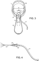
- Figure 3 illustrates a rear-view of the joined speculum blades (1, 2), the extension shaft (8) and the nozzle (7).
- the dimensions of the cross section (40) of the nozzle are substantially smaller than the dimensions of the cross section (41) of a rear aperture (42) of the blade system, thus allowing for the visualization of the examined area before, during, and after the injection of the marker.
- Figure 4 illustrates a needle nozzle (27), with the needle (43) having an outside diameter sized to maximize the field-of-view through the rear aperture (42) of the blade system.
- a coupling mechanism (28) is used for the connection of the needle nozzle (27) with the tube (17) providing a channel for the marker from a container holding the marker to an input orifice of the coupling means (28).
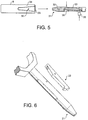
- FIG. 5 and 6 illustrate one example of the shaft (8) in more detail.
- the shaft (8) illustrated in Figure 5 is well suited for use in securing the speculum shaft onto an optical imaging system (26), onto a base member (23), or both.
- the distal end (29) of a speculum shaft (8) includes a conically tapered slot (30) in a bottom side.
- the conically tapered slot (30) acts as a guide for the proper alignment of the speculum with respect to the external optical system (26).
- a securing mechanism engages with the distal end (29) of the shaft (8) with an extension pin (31) that has a dowel pin (32) having a longitudinal axis perpendicular to the longitudinal axis of the extension pin (31).
- the position of the dowel pin (32) determines the displacement of the speculum from the external optical system.
- the distal end (29) of the shaft (8) engages with the extension pin (31) using a spring-loaded, cam action wedge (33).
- the distal end (29) of the shaft (8) also includes a receptacle slot (34) to mate with the cam action wedge (33).
- the shaft (8) is moved towards the optical system to urge the dowel pin (32) into contact with the conically tapered groove (30) in the shaft (8) until the cam action wedge (33) mates with the receptacle slot (34) in the shaft (8).
- the shaft (8) is unlocked from the dowel pin (32) by pressing on a release button (35) which has the effect of engaging with the cam action wedge (33).
- the receptacle slot (34) is devoid of a locking member and the shaft (8) can be removed.
- the cam action wedge (33) and the release button (35) are returned to their normal states due to the action of a spring (36) housed in the engagement pin (31).
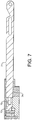
- the vaginal speculum may be attached to the support with the use of a magnetic locking mechanism.
- the mechanism may consist of a connecting shaft (71) with a ferrite insert at the distal end (72) and a corresponding magnet (73) housed in the support.
- the said magnet (73) may be a permanent magnet, or in another embodiment, an electromagnet.
- the support is designed with a conical inlet (74) in order to provide accurate alignment, ease of engagement and elimination of unwanted clearances at the junction of the connecting shaft and the support.
- the magnet (73) is a permanent magnet.
- the vaginal speculum connected to the connecting shaft (71) is brought into the proximity of the permanent magnet by using the guidance provided by the conical opening in the support.
- the connecting shaft is de-coupled from the support by using an ambidextrous release trigger (not shown) and pulling it.
- the pivot action of the trigger causes the support - connection shaft connection to be severed.
- the vaginal speculum and the connection shaft may then be extricated from the support.
- the magnet used may be an electromagnet whereby the "circuit" is completed upon contact of the inserted ferrite with the corresponding contact point in the support.
- the release of the connection in this embodiment may be effected by using a wired button to interrupt the circuit allowing the release of the connection shaft from the support.
Landscapes
- Health & Medical Sciences (AREA)
- Life Sciences & Earth Sciences (AREA)
- Surgery (AREA)
- Animal Behavior & Ethology (AREA)
- Public Health (AREA)
- Optics & Photonics (AREA)
- Pathology (AREA)
- Radiology & Medical Imaging (AREA)
- Biophysics (AREA)
- Engineering & Computer Science (AREA)
- Biomedical Technology (AREA)
- Heart & Thoracic Surgery (AREA)
- Medical Informatics (AREA)
- Molecular Biology (AREA)
- Physics & Mathematics (AREA)
- General Health & Medical Sciences (AREA)
- Nuclear Medicine, Radiotherapy & Molecular Imaging (AREA)
- Veterinary Medicine (AREA)
- Gynecology & Obstetrics (AREA)
- Reproductive Health (AREA)
- Endoscopes (AREA)
- Devices That Are Associated With Refrigeration Equipment (AREA)
- Electrically Driven Valve-Operating Means (AREA)
- Rolls And Other Rotary Bodies (AREA)
- Investigating Or Analysing Biological Materials (AREA)
- Surgical Instruments (AREA)
- Percussion Or Vibration Massage (AREA)
- Ultra Sonic Daignosis Equipment (AREA)
Claims (21)
- Vaginalspekulumanordnung, welche umfasst
ein Blattsystem zum Öffnen der Vagina mit einem erstem Blatt (1) und einem zweiten Blatt (2), die relativ zueinander in einer Vielzahl von Winkeln positionierbar sind, und einer Längssymmetrieachse (10) zwischen einem distalen Abschnitt und einem proximalen Abschnitt des ersten (1) und des zweiten Blatts (2); und
eine mechanische Stütze, die einen Schaft (8) mit einem ersten Schaftende, das mechanisch mit dem Blattsystem gekoppelt ist, und einem zweiten Schaftende, das lösbar mit einem Einspritzmechanismus, einem Stützelement oder einer Abbildungsvorrichtung kuppelbar ist, umfasst;
dadurch gekennzeichnet, dass
das erste Wellenende des Schafts (8) mit einer Blatt-Griff-Verbindung des ersten Blatts (6) verbunden ist, und eine Struktur der Blatt-Griff-Verbindung des zweiten Blatts (6) konfiguriert ist, um sich entlang einer Struktur zu bewegen, die entlang einer Längsachse des Schafts (8) ausgebildet ist. - Vaginalspekulumanordnung nach Anspruch 1, ferner mit einem Injektionsmechanismus, wobei:das zweite Schaftende mit einem Injektionsmechanismus zur Abgabe eines Diagnosemarkers auf die untersuchte Gewebeoberfläche lösbar gekoppelt ist, der eine Injektionssonde (7) mit einer Längsachse (11), einen Markerbehälter (15, 16) und ein Mittel zum Ermöglichen der Injektion des Markers (18) aufweist, wobei die Abmessungen des Querschnitts der Injektionssonde (40) wesentlich kleiner sind als die Abmessungen des Querschnitts (41) einer hinteren Öffnung (42) des Blattsystems, undwobei die relative Position der Längsachse der Injektionssonde (11) und der Längssymmetrieachse des Blattsystems (10) für jeden der Vielzahl von Winkeln zwischen dem ersten und dem zweiten Blatt im Wesentlichen fixiert bleibt, wobei die Injektionssonde (7) eine im Wesentlichen homogene Applikation des Diagnosemarkers auf einen gewünschten Bereich im untersuchten vaginalen oder zervikalen Gewebe unabhängig vom Öffnungswinkel der Blätter (1, 2) ermöglicht und die Beobachtung des gewünschten Bereichs durch die hintere Öffnung des Blattsystems vor und nach der Injektion des Diagnosemarkers ermöglicht.
- Vaginalspekulumanordnung nach Anspruch 2, wobei das zweite Wellenende lösbar mit einem Trägerelement oder einem Abbildungsgerät gekoppelt ist.
- Vaginalspekulumanordnung nach Anspruch 2, wobei die Injektionssonde (7) an einem Teil des Schafts (8) angebracht ist.
- Vaginalspekulumanordnung nach einem der Ansprüche 3 oder 4, wobei der Schaft (8) einen Verriegelungsmechanismus aufweist.
- Vaginalspekulumanordnung nach Anspruch 3, wobei das Stützelement einen Gelenkarm (22) mit einem ersten Endabschnitt, der an einer Basis (23) befestigt ist, und einem zweiten Endabschnitt, der an einem Verriegelungsmechanismus des Schaftes (21) befestigt ist, aufweist.
- Vaginalspekulumanordnung nach Anspruch 3 oder 4, wobei der Verriegelungsmechanismus (21) einen mechanischen Verriegelungsmechanismus oder einen magnetischen oder einen elektromagnetischen Verriegelungsmechanismus umfasst.
- Vaginalspekulumanordnung nach Anspruch 5, wobei die Injektionssonde (7) an der mechanischen Basis in der Nähe des Verriegelungsmechanismus befestigt ist.
- Vaginalspekulumanordnung nach einem der Ansprüche 2 bis 8, wobei die Injektionssonde (7) eine Düse umfasst.
- Vaginalspekulumanordnung nach Anspruch 9, wobei die Düse (7) eine Nadeldüse (43) umfasst.
- umfasst Vaginalspekulumanordnung nach einem der Ansprüche 2 bis 10, wobei der Injektionsmechanismus ferner eine hydraulische Pumpeinrichtung (15, 16, 18, 19, 20) zum Pumpen eines vorbestimmten Volumens eines Markers in und durch die Injektionssonde (7) umfasst.
- Vaginalspekulumanordnung nach Anspruch 11, wobei das vorbestimmte Volumen des Markers zwischen etwa 2,5 ml und etwa 3,5 ml liegt.
- Vaginalspekulumanordnung nach Anspruch 11 oder 12, wobei der Marker eine zwischen etwa 3%ige und etwa 5%ige Essigsäurelösung ist.
- Vaginalspekulumanordnung nach einem der Ansprüche 2 bis 13, die ferner eine Lichtquelle (24) umfasst.
- Vaginalspekulumanordnung nach einem der Ansprüche 5 bis 8, welche ferner eine Lichtquelle (24), die an dem Stützelement in der Nähe des Schaftverriegelungsmechanismus (21) befestigt ist umfasst.
- Vaginalspekulumanordnung nach einem der Ansprüche 2 bis 15, welche ferner ein optisches Element (26) umfasst.
- Vaginalspekulumanordnung nach Anspruch 16, wobei das optische Element (26) ein vergrößerndes optisches Element, ein fokussierbares optisches Element, einen optischen Filter oder ein Paar von Polarisatoren umfasst, einen zum Polarisieren des von der Lichtquelle emittierten Lichts und einen zum Polarisieren des vom Gewebe reflektierten Lichts, deren Polarisationsachsen senkrecht zueinander stehen.
- Vaginalspekulumanordnung nach einem der Ansprüche 2 bis 17, wobei das Blattsystem/der Schaft (8)/die Injektionssonde (7) aus einem metallischen Material gebildet sind.
- Vaginalspekulumanordnung nach Anspruch 18, wobei das Blattsystem/der Schaft (8) /die Injektionssonde (7) wiederverwendbar sind.
- Vaginalspekulumanordnung nach einem der Ansprüche 2 bis 17, wobei das Blattsystem/der Schaft (8)/die Injektionsmittel (7) einen Abschnitt umfassen, der aus einer Polymerverbindung gebildet ist.
- Vaginalspekulumanordnung nach Anspruch 20, wobei das Blattsystem/der Schaft (8)/die Injektionsmittel (7) wegwerfbar sind.
Priority Applications (1)
| Application Number | Priority Date | Filing Date | Title |
|---|---|---|---|
| EP06794602.0A EP1928293B8 (de) | 2005-09-29 | 2006-09-29 | Vaginale spekulumanordnung |
Applications Claiming Priority (3)
| Application Number | Priority Date | Filing Date | Title |
|---|---|---|---|
| EP05386023A EP1769731B1 (de) | 2005-09-29 | 2005-09-29 | Vaginalspekulum |
| EP06794602.0A EP1928293B8 (de) | 2005-09-29 | 2006-09-29 | Vaginale spekulumanordnung |
| PCT/GB2006/003648 WO2007036744A2 (en) | 2005-09-29 | 2006-09-29 | Vaginal speculum arrangement |
Publications (3)
| Publication Number | Publication Date |
|---|---|
| EP1928293A2 EP1928293A2 (de) | 2008-06-11 |
| EP1928293B1 true EP1928293B1 (de) | 2018-09-05 |
| EP1928293B8 EP1928293B8 (de) | 2018-10-24 |
Family
ID=36170061
Family Applications (2)
| Application Number | Title | Priority Date | Filing Date |
|---|---|---|---|
| EP05386023A Expired - Lifetime EP1769731B1 (de) | 2005-09-29 | 2005-09-29 | Vaginalspekulum |
| EP06794602.0A Active EP1928293B8 (de) | 2005-09-29 | 2006-09-29 | Vaginale spekulumanordnung |
Family Applications Before (1)
| Application Number | Title | Priority Date | Filing Date |
|---|---|---|---|
| EP05386023A Expired - Lifetime EP1769731B1 (de) | 2005-09-29 | 2005-09-29 | Vaginalspekulum |
Country Status (10)
| Country | Link |
|---|---|
| US (1) | US20080306345A1 (de) |
| EP (2) | EP1769731B1 (de) |
| JP (1) | JP5380071B2 (de) |
| CN (1) | CN101277641B (de) |
| AT (1) | ATE424755T1 (de) |
| DE (1) | DE602005013228D1 (de) |
| DK (1) | DK1769731T3 (de) |
| ES (1) | ES2322481T3 (de) |
| PT (2) | PT1769731E (de) |
| WO (1) | WO2007036744A2 (de) |
Families Citing this family (33)
| Publication number | Priority date | Publication date | Assignee | Title |
|---|---|---|---|---|
| EP1865824A4 (de) | 2005-04-01 | 2009-06-03 | Welch Allyn Inc | Vaginalspekulumvorrichtung |
| US20090076368A1 (en) * | 2007-04-11 | 2009-03-19 | Forth Photonics Ltd. | Integrated imaging workstation and a method for improving, objectifying and documenting in vivo examinations of the uterus |
| GB2467573B (en) * | 2009-02-06 | 2011-01-12 | Parburch Medical Developments Ltd | Proctoscope |
| US20100305406A1 (en) * | 2009-05-26 | 2010-12-02 | Ori Braun | System, device and method for gynecological use |
| US8638995B2 (en) | 2009-11-10 | 2014-01-28 | Illumigyn Ltd. | Optical speculum |
| US9271640B2 (en) | 2009-11-10 | 2016-03-01 | Illumigyn Ltd. | Optical speculum |
| US9877644B2 (en) | 2009-11-10 | 2018-01-30 | Illumigyn Ltd. | Optical speculum |
| IT1405000B1 (it) * | 2010-02-04 | 2013-12-16 | El En Spa | Dispositivo per il trattamento del canale vaginale e relativo apparecchio |
| CN102525393A (zh) * | 2012-01-18 | 2012-07-04 | 师伟 | 大鼠固定式自照明阴道窥器 |
| CN103142207B (zh) * | 2013-03-19 | 2015-06-17 | 亚新科技(珠海)发展有限公司 | 一种用于宫颈手术的装置 |
| JP6426160B2 (ja) * | 2013-06-05 | 2018-11-21 | エスエヌピーショット トラスティ— リミテッド | 組織試料採取における改良および組織試料採取に関連する改良 |
| EP3038543A4 (de) | 2013-08-28 | 2017-03-22 | Alfred E. Mann Institute for Biomedical Engineering at the University of Southern California | Minimal-obstruktiver retraktor für vaginale reparaturen |
| US20170181607A1 (en) | 2015-12-29 | 2017-06-29 | CEEK Enterprises | Insertable sleeve for speculum and use thereof |
| CA3209391A1 (en) * | 2015-12-29 | 2017-07-06 | Ceek Women's Health, Inc. | Speculum with secondary bills |
| CA3208684A1 (en) | 2015-12-29 | 2017-07-06 | Ceek Women's Health, Inc. | Sleeve for speculum and use thereof |
| CN105708410B (zh) * | 2016-01-20 | 2018-05-22 | 广州普露医疗科技有限公司 | 阴道子宫颈检治仪 |
| US11259785B2 (en) | 2016-09-16 | 2022-03-01 | Lida Aghdam | Vagina probe with brush |
| US20180177989A1 (en) * | 2016-12-28 | 2018-06-28 | Regen Medical Inc. | Vaginal rejuvenation methods and devices |
| US10687699B2 (en) | 2017-03-17 | 2020-06-23 | CEEK Enterprises | Lighting module for a medical device and methods for using the same |
| CN106963379B (zh) * | 2017-03-17 | 2020-08-21 | 中国人民解放军第三军医大学第一附属医院 | 一种太赫兹成像系统 |
| USD963908S1 (en) | 2017-03-24 | 2022-09-13 | Ceek Women's Health, Inc. | Medical device lighting module |
| JP6926631B2 (ja) * | 2017-04-25 | 2021-08-25 | ウシオ電機株式会社 | 蛍光観察ユニット |
| CN107260115B (zh) * | 2017-07-26 | 2023-06-23 | 浙江百安医疗科技有限公司 | 具有连接环的阴道窥镜 |
| JP6516339B1 (ja) * | 2018-03-12 | 2019-05-22 | 株式会社ナミキ・メディカルインストゥルメンツ | 医療器具 |
| CN108634922A (zh) * | 2018-04-23 | 2018-10-12 | 山东丽鱼家具有限公司 | 一种妇产科检查清洗用扩阴器 |
| CN111643799B (zh) * | 2020-06-16 | 2021-10-01 | 徐伟伟 | 一种妇产科用给药装置 |
| MX392705B (es) | 2020-07-13 | 2025-03-19 | Villa Juan Gerardo Barroso | Estabilizador de cánula para transferencia embrionaria. |
| WO2022010845A1 (en) * | 2020-07-06 | 2022-01-13 | Maine Medical Center | Diagnostic cervical scanning and treatment device |
| USD986415S1 (en) | 2020-09-11 | 2023-05-16 | Ceek Women's Health, Inc. | Speculum |
| KR102369740B1 (ko) * | 2020-09-21 | 2022-03-02 | 부경대학교 산학협력단 | 자궁경부암 조기진단을 위한 모바일 질확대경 장치 |
| CN114403945B (zh) * | 2022-01-24 | 2024-06-18 | 杨霞 | 一种妇科宫颈疾病智能化检查诊治系统 |
| CN114366013B (zh) * | 2022-01-28 | 2025-07-18 | 中国人民解放军陆军军医大学第一附属医院 | 一种可视化阴道宫颈检查器械 |
| KR102931824B1 (ko) | 2023-12-15 | 2026-02-25 | 고신대학교 산학협력단 | 모바일 질확대경에 탈부착 가능한 검사용액 분무 및 조직채취 장치 |
Citations (1)
| Publication number | Priority date | Publication date | Assignee | Title |
|---|---|---|---|---|
| US6432049B1 (en) * | 2000-08-29 | 2002-08-13 | Linda Kay Banta | Adjustable vaginal speculum light |
Family Cites Families (25)
| Publication number | Priority date | Publication date | Assignee | Title |
|---|---|---|---|---|
| GB191027965A (en) | 1910-02-17 | 1911-04-06 | Marcel Meyer | Improvements in Therapeutic Injecting Apparatus. |
| GB214913A (en) | 1923-09-29 | 1924-05-01 | Howard Glenn Carter | Improvements in vaginal syringes |
| US3815585A (en) * | 1971-01-14 | 1974-06-11 | Bio Analytical Labor Inc | Disposable vaginal speculum |
| US3789829A (en) * | 1971-06-01 | 1974-02-05 | H Hasson | Vaginal radium applicator |
| US3762400A (en) | 1971-10-26 | 1973-10-02 | Donald B Mc | Medical examining instrument |
| US3851642A (en) | 1971-10-26 | 1974-12-03 | Medical Testing Syst Inc | Medical examining instrument |
| US4046140A (en) | 1972-06-02 | 1977-09-06 | Born Grant R | Cervix photographic method |
| GB1408382A (en) | 1972-08-14 | 1975-10-01 | Mcdonald B | Specula |
| CH609549A5 (en) * | 1975-10-21 | 1979-03-15 | Ortiz Castaneda Jimeno | Device for microscopic examination of the vagina |
| US4210133A (en) | 1975-10-21 | 1980-07-01 | Consejo Nacional De Ciencia Y Tecnologia | Vaginal microscope |
| US4905670A (en) | 1988-12-28 | 1990-03-06 | Adair Edwin Lloyd | Apparatus for cervical videoscopy |
| US5143054A (en) * | 1988-12-28 | 1992-09-01 | Adair Edwin Lloyd | Cervical videoscope with detachable camera unit |
| US5072720A (en) * | 1990-01-08 | 1991-12-17 | Francis Walter C | Vaginal speculum |
| JP2768532B2 (ja) * | 1990-02-02 | 1998-06-25 | エル アデア エドウィン | 頚部観察装置 |
| JP3192147B2 (ja) * | 1991-12-03 | 2001-07-23 | ボストン サイエンティフィック アイルランド リミテッド,バーバドス ヘッド オフィス | 骨アンカー挿入装置 |
| WO1993023552A1 (en) * | 1992-05-21 | 1993-11-25 | Government Of The United States As Represented By Secretary Department Of Health And Human Services | Targeting gene expression to living tissue using jet injection |
| US5458595A (en) * | 1993-12-16 | 1995-10-17 | The Regents Of The University Of California | Vaginal speculum for photodynamic therapy and method of using the same |
| US5846249A (en) | 1996-02-07 | 1998-12-08 | Pinotage, Llc | Video gynecological examination apparatus |
| US5951461A (en) * | 1996-12-20 | 1999-09-14 | Nyo; Tin | Image-guided laryngoscope for tracheal intubation |
| US20020007122A1 (en) * | 1999-12-15 | 2002-01-17 | Howard Kaufman | Methods of diagnosing disease |
| GR1004180B (el) * | 2000-03-28 | 2003-03-11 | ����������� ����� ��������� (����) | Μεθοδος και συστημα χαρακτηρισμου και χαρτογραφησης αλλοιωσεων των ιστων |
| US20040122327A1 (en) | 2000-12-15 | 2004-06-24 | Amir Belson | Intrauterine imaging system |
| US6712761B2 (en) * | 2002-06-04 | 2004-03-30 | German Borodulin | Combination of a vaginal speculum with a single-lens colposcope |
| EP1720444A4 (de) * | 2003-12-15 | 2010-11-17 | Uset Medical Ltd | Vaginale spekulum-anordnung |
| US8142352B2 (en) * | 2006-04-03 | 2012-03-27 | Welch Allyn, Inc. | Vaginal speculum assembly having portable illuminator |
-
2005
- 2005-09-29 ES ES05386023T patent/ES2322481T3/es not_active Expired - Lifetime
- 2005-09-29 DE DE602005013228T patent/DE602005013228D1/de not_active Expired - Lifetime
- 2005-09-29 EP EP05386023A patent/EP1769731B1/de not_active Expired - Lifetime
- 2005-09-29 AT AT05386023T patent/ATE424755T1/de active
- 2005-09-29 DK DK05386023T patent/DK1769731T3/da active
- 2005-09-29 PT PT05386023T patent/PT1769731E/pt unknown
-
2006
- 2006-09-29 WO PCT/GB2006/003648 patent/WO2007036744A2/en not_active Ceased
- 2006-09-29 CN CN2006800359963A patent/CN101277641B/zh not_active Expired - Fee Related
- 2006-09-29 JP JP2008532877A patent/JP5380071B2/ja not_active Expired - Fee Related
- 2006-09-29 EP EP06794602.0A patent/EP1928293B8/de active Active
- 2006-09-29 US US12/088,289 patent/US20080306345A1/en not_active Abandoned
- 2006-09-29 PT PT06794602T patent/PT1928293T/pt unknown
Patent Citations (1)
| Publication number | Priority date | Publication date | Assignee | Title |
|---|---|---|---|---|
| US6432049B1 (en) * | 2000-08-29 | 2002-08-13 | Linda Kay Banta | Adjustable vaginal speculum light |
Also Published As
| Publication number | Publication date |
|---|---|
| PT1769731E (pt) | 2009-04-03 |
| PT1928293T (pt) | 2018-12-03 |
| EP1928293A2 (de) | 2008-06-11 |
| WO2007036744A3 (en) | 2007-06-14 |
| EP1769731B1 (de) | 2009-03-11 |
| WO2007036744A2 (en) | 2007-04-05 |
| EP1928293B8 (de) | 2018-10-24 |
| DE602005013228D1 (de) | 2009-04-23 |
| ATE424755T1 (de) | 2009-03-15 |
| JP2009509606A (ja) | 2009-03-12 |
| ES2322481T3 (es) | 2009-06-22 |
| US20080306345A1 (en) | 2008-12-11 |
| JP5380071B2 (ja) | 2014-01-08 |
| CN101277641A (zh) | 2008-10-01 |
| CN101277641B (zh) | 2010-06-16 |
| DK1769731T3 (da) | 2009-07-06 |
| EP1769731A1 (de) | 2007-04-04 |
Similar Documents
| Publication | Publication Date | Title |
|---|---|---|
| EP1928293B1 (de) | Vaginale spekulumanordnung | |
| US6712761B2 (en) | Combination of a vaginal speculum with a single-lens colposcope | |
| US7749162B2 (en) | Vaginal speculum arrangement | |
| US9877644B2 (en) | Optical speculum | |
| US20070213590A1 (en) | Apparatus and methods for examining, visualizing, diagnosing, manipulating, treating and recording of abnormalities within interior regions of body cavities | |
| US20230022536A1 (en) | Brush biopsy device, kit and method | |
| US7515952B2 (en) | System for characterization and mapping of tissue lesions | |
| US20060241347A1 (en) | Systems and methods relating to colposcopic viewing tubes for enhanced viewing and examination | |
| KR102567918B1 (ko) | 광학 검경 | |
| US20100305406A1 (en) | System, device and method for gynecological use | |
| IL273798B1 (en) | Colposcopes, the scopes and inserts that have curved tips and related methods | |
| WO2015007233A1 (zh) | 一种头端可弯曲的输尿管肾镜 | |
| JP2003534056A (ja) | 観察機能を備えるガイドワイヤ | |
| JP6830356B2 (ja) | 子宮を連続的に検知するための監視システム | |
| NL1027678C2 (nl) | Inrichting en werkwijze voor onderzoek van een lichaamsholte. | |
| CN204562076U (zh) | 鼻咽镜 | |
| CN106419822B (zh) | 一种一体化关节镜装置 | |
| CN112137584A (zh) | 具有活检功能的皮肤检查器械 | |
| CN217338538U (zh) | 一种双模态光学相干断层扫描内窥探头 | |
| CN206390889U (zh) | 一种一体化关节镜装置 | |
| CN209734014U (zh) | 一种超声波三维扫描显微鼻咽镜 | |
| WO2009059355A1 (en) | Examination device | |
| CN215227415U (zh) | 硬管电子内窥镜 | |
| WO2007131263A1 (en) | Examination device | |
| WO2023085917A1 (es) | Aparato auxiliar en el diagnóstico del cáncer cervicouterino |
Legal Events
| Date | Code | Title | Description |
|---|---|---|---|
| PUAI | Public reference made under article 153(3) epc to a published international application that has entered the european phase |
Free format text: ORIGINAL CODE: 0009012 |
|
| 17P | Request for examination filed |
Effective date: 20080331 |
|
| AK | Designated contracting states |
Kind code of ref document: A2 Designated state(s): AT BE BG CH CY CZ DE DK EE ES FI FR GB GR HU IE IS IT LI LT LU LV MC NL PL PT RO SE SI SK TR |
|
| DAX | Request for extension of the european patent (deleted) | ||
| 17Q | First examination report despatched |
Effective date: 20141111 |
|
| RAP1 | Party data changed (applicant data changed or rights of an application transferred) |
Owner name: DYSIS MEDICAL LIMITED |
|
| REG | Reference to a national code |
Ref country code: DE Ref legal event code: R079 Ref document number: 602006056268 Country of ref document: DE Free format text: PREVIOUS MAIN CLASS: A61B0001303000 Ipc: A61B0001000000 |
|
| RIC1 | Information provided on ipc code assigned before grant |
Ipc: A61B 1/303 20060101ALI20170811BHEP Ipc: A61B 1/015 20060101ALI20170811BHEP Ipc: A61B 1/00 20060101AFI20170811BHEP |
|
| GRAP | Despatch of communication of intention to grant a patent |
Free format text: ORIGINAL CODE: EPIDOSNIGR1 |
|
| INTG | Intention to grant announced |
Effective date: 20171006 |
|
| GRAJ | Information related to disapproval of communication of intention to grant by the applicant or resumption of examination proceedings by the epo deleted |
Free format text: ORIGINAL CODE: EPIDOSDIGR1 |
|
| GRAP | Despatch of communication of intention to grant a patent |
Free format text: ORIGINAL CODE: EPIDOSNIGR1 |
|
| INTC | Intention to grant announced (deleted) | ||
| INTG | Intention to grant announced |
Effective date: 20180315 |
|
| GRAS | Grant fee paid |
Free format text: ORIGINAL CODE: EPIDOSNIGR3 |
|
| GRAA | (expected) grant |
Free format text: ORIGINAL CODE: 0009210 |
|
| GRAT | Correction requested after decision to grant or after decision to maintain patent in amended form |
Free format text: ORIGINAL CODE: EPIDOSNCDEC |
|
| AK | Designated contracting states |
Kind code of ref document: B1 Designated state(s): AT BE BG CH CY CZ DE DK EE ES FI FR GB GR HU IE IS IT LI LT LU LV MC NL PL PT RO SE SI SK TR |
|
| RAP1 | Party data changed (applicant data changed or rights of an application transferred) |
Owner name: DYSIS MEDICAL LIMITED |
|
| REG | Reference to a national code |
Ref country code: GB Ref legal event code: FG4D |
|
| REG | Reference to a national code |
Ref country code: CH Ref legal event code: EP |
|
| REG | Reference to a national code |
Ref country code: AT Ref legal event code: REF Ref document number: 1036854 Country of ref document: AT Kind code of ref document: T Effective date: 20180915 |
|
| RAP2 | Party data changed (patent owner data changed or rights of a patent transferred) |
Owner name: DYSIS MEDICAL LIMITED |
|
| REG | Reference to a national code |
Ref country code: CH Ref legal event code: PK Free format text: BERICHTIGUNG B8 |
|
| REG | Reference to a national code |
Ref country code: IE Ref legal event code: FG4D |
|
| REG | Reference to a national code |
Ref country code: DE Ref legal event code: R096 Ref document number: 602006056268 Country of ref document: DE |
|
| REG | Reference to a national code |
Ref country code: FR Ref legal event code: PLFP Year of fee payment: 13 |
|
| REG | Reference to a national code |
Ref country code: CH Ref legal event code: NV Representative=s name: KIRKER AND CIE S.A., CH |
|
| REG | Reference to a national code |
Ref country code: PT Ref legal event code: SC4A Ref document number: 1928293 Country of ref document: PT Date of ref document: 20181203 Kind code of ref document: T Free format text: AVAILABILITY OF NATIONAL TRANSLATION Effective date: 20181126 |
|
| REG | Reference to a national code |
Ref country code: NL Ref legal event code: FP |
|
| REG | Reference to a national code |
Ref country code: SE Ref legal event code: TRGR |
|
| REG | Reference to a national code |
Ref country code: LT Ref legal event code: MG4D |
|
| PG25 | Lapsed in a contracting state [announced via postgrant information from national office to epo] |
Ref country code: FI Free format text: LAPSE BECAUSE OF FAILURE TO SUBMIT A TRANSLATION OF THE DESCRIPTION OR TO PAY THE FEE WITHIN THE PRESCRIBED TIME-LIMIT Effective date: 20180905 Ref country code: BG Free format text: LAPSE BECAUSE OF FAILURE TO SUBMIT A TRANSLATION OF THE DESCRIPTION OR TO PAY THE FEE WITHIN THE PRESCRIBED TIME-LIMIT Effective date: 20181205 Ref country code: LT Free format text: LAPSE BECAUSE OF FAILURE TO SUBMIT A TRANSLATION OF THE DESCRIPTION OR TO PAY THE FEE WITHIN THE PRESCRIBED TIME-LIMIT Effective date: 20180905 |
|
| PG25 | Lapsed in a contracting state [announced via postgrant information from national office to epo] |
Ref country code: LV Free format text: LAPSE BECAUSE OF FAILURE TO SUBMIT A TRANSLATION OF THE DESCRIPTION OR TO PAY THE FEE WITHIN THE PRESCRIBED TIME-LIMIT Effective date: 20180905 Ref country code: ES Free format text: LAPSE BECAUSE OF FAILURE TO SUBMIT A TRANSLATION OF THE DESCRIPTION OR TO PAY THE FEE WITHIN THE PRESCRIBED TIME-LIMIT Effective date: 20180905 |
|
| REG | Reference to a national code |
Ref country code: GR Ref legal event code: EP Ref document number: 20180403662 Country of ref document: GR Effective date: 20190404 |
|
| PG25 | Lapsed in a contracting state [announced via postgrant information from national office to epo] |
Ref country code: CZ Free format text: LAPSE BECAUSE OF FAILURE TO SUBMIT A TRANSLATION OF THE DESCRIPTION OR TO PAY THE FEE WITHIN THE PRESCRIBED TIME-LIMIT Effective date: 20180905 Ref country code: RO Free format text: LAPSE BECAUSE OF FAILURE TO SUBMIT A TRANSLATION OF THE DESCRIPTION OR TO PAY THE FEE WITHIN THE PRESCRIBED TIME-LIMIT Effective date: 20180905 Ref country code: IS Free format text: LAPSE BECAUSE OF FAILURE TO SUBMIT A TRANSLATION OF THE DESCRIPTION OR TO PAY THE FEE WITHIN THE PRESCRIBED TIME-LIMIT Effective date: 20190105 Ref country code: PL Free format text: LAPSE BECAUSE OF FAILURE TO SUBMIT A TRANSLATION OF THE DESCRIPTION OR TO PAY THE FEE WITHIN THE PRESCRIBED TIME-LIMIT Effective date: 20180905 Ref country code: EE Free format text: LAPSE BECAUSE OF FAILURE TO SUBMIT A TRANSLATION OF THE DESCRIPTION OR TO PAY THE FEE WITHIN THE PRESCRIBED TIME-LIMIT Effective date: 20180905 |
|
| PG25 | Lapsed in a contracting state [announced via postgrant information from national office to epo] |
Ref country code: SK Free format text: LAPSE BECAUSE OF FAILURE TO SUBMIT A TRANSLATION OF THE DESCRIPTION OR TO PAY THE FEE WITHIN THE PRESCRIBED TIME-LIMIT Effective date: 20180905 |
|
| REG | Reference to a national code |
Ref country code: DE Ref legal event code: R097 Ref document number: 602006056268 Country of ref document: DE |
|
| PG25 | Lapsed in a contracting state [announced via postgrant information from national office to epo] |
Ref country code: LU Free format text: LAPSE BECAUSE OF NON-PAYMENT OF DUE FEES Effective date: 20180929 |
|
| PLBE | No opposition filed within time limit |
Free format text: ORIGINAL CODE: 0009261 |
|
| STAA | Information on the status of an ep patent application or granted ep patent |
Free format text: STATUS: NO OPPOSITION FILED WITHIN TIME LIMIT |
|
| PG25 | Lapsed in a contracting state [announced via postgrant information from national office to epo] |
Ref country code: MC Free format text: LAPSE BECAUSE OF FAILURE TO SUBMIT A TRANSLATION OF THE DESCRIPTION OR TO PAY THE FEE WITHIN THE PRESCRIBED TIME-LIMIT Effective date: 20180905 Ref country code: DK Free format text: LAPSE BECAUSE OF FAILURE TO SUBMIT A TRANSLATION OF THE DESCRIPTION OR TO PAY THE FEE WITHIN THE PRESCRIBED TIME-LIMIT Effective date: 20180905 |
|
| 26N | No opposition filed |
Effective date: 20190606 |
|
| REG | Reference to a national code |
Ref country code: AT Ref legal event code: UEP Ref document number: 1036854 Country of ref document: AT Kind code of ref document: T Effective date: 20180905 |
|
| PG25 | Lapsed in a contracting state [announced via postgrant information from national office to epo] |
Ref country code: SI Free format text: LAPSE BECAUSE OF FAILURE TO SUBMIT A TRANSLATION OF THE DESCRIPTION OR TO PAY THE FEE WITHIN THE PRESCRIBED TIME-LIMIT Effective date: 20180905 |
|
| PG25 | Lapsed in a contracting state [announced via postgrant information from national office to epo] |
Ref country code: TR Free format text: LAPSE BECAUSE OF FAILURE TO SUBMIT A TRANSLATION OF THE DESCRIPTION OR TO PAY THE FEE WITHIN THE PRESCRIBED TIME-LIMIT Effective date: 20180905 |
|
| PG25 | Lapsed in a contracting state [announced via postgrant information from national office to epo] |
Ref country code: HU Free format text: LAPSE BECAUSE OF FAILURE TO SUBMIT A TRANSLATION OF THE DESCRIPTION OR TO PAY THE FEE WITHIN THE PRESCRIBED TIME-LIMIT; INVALID AB INITIO Effective date: 20060929 |
|
| PG25 | Lapsed in a contracting state [announced via postgrant information from national office to epo] |
Ref country code: CY Free format text: LAPSE BECAUSE OF FAILURE TO SUBMIT A TRANSLATION OF THE DESCRIPTION OR TO PAY THE FEE WITHIN THE PRESCRIBED TIME-LIMIT Effective date: 20180905 |
|
| PGFP | Annual fee paid to national office [announced via postgrant information from national office to epo] |
Ref country code: NL Payment date: 20230921 Year of fee payment: 18 Ref country code: IE Payment date: 20230922 Year of fee payment: 18 Ref country code: GB Payment date: 20230919 Year of fee payment: 18 Ref country code: AT Payment date: 20230921 Year of fee payment: 18 |
|
| PGFP | Annual fee paid to national office [announced via postgrant information from national office to epo] |
Ref country code: SE Payment date: 20230929 Year of fee payment: 18 Ref country code: PT Payment date: 20230926 Year of fee payment: 18 Ref country code: GR Payment date: 20230925 Year of fee payment: 18 Ref country code: FR Payment date: 20230922 Year of fee payment: 18 Ref country code: DE Payment date: 20230921 Year of fee payment: 18 Ref country code: BE Payment date: 20230921 Year of fee payment: 18 |
|
| PGFP | Annual fee paid to national office [announced via postgrant information from national office to epo] |
Ref country code: IT Payment date: 20230926 Year of fee payment: 18 Ref country code: CH Payment date: 20231001 Year of fee payment: 18 |
|
| REG | Reference to a national code |
Ref country code: DE Ref legal event code: R119 Ref document number: 602006056268 Country of ref document: DE |
|
| PG25 | Lapsed in a contracting state [announced via postgrant information from national office to epo] |
Ref country code: PT Free format text: LAPSE BECAUSE OF NON-PAYMENT OF DUE FEES Effective date: 20250331 |
|
| REG | Reference to a national code |
Ref country code: SE Ref legal event code: EUG |
|
| REG | Reference to a national code |
Ref country code: CH Ref legal event code: PL |
|
| REG | Reference to a national code |
Ref country code: NL Ref legal event code: MM Effective date: 20241001 |
|
| REG | Reference to a national code |
Ref country code: AT Ref legal event code: MM01 Ref document number: 1036854 Country of ref document: AT Kind code of ref document: T Effective date: 20240929 |
|
| GBPC | Gb: european patent ceased through non-payment of renewal fee |
Effective date: 20240929 |
|
| PG25 | Lapsed in a contracting state [announced via postgrant information from national office to epo] |
Ref country code: NL Free format text: LAPSE BECAUSE OF NON-PAYMENT OF DUE FEES Effective date: 20241001 |
|
| PG25 | Lapsed in a contracting state [announced via postgrant information from national office to epo] |
Ref country code: DE Free format text: LAPSE BECAUSE OF NON-PAYMENT OF DUE FEES Effective date: 20250401 |
|
| PG25 | Lapsed in a contracting state [announced via postgrant information from national office to epo] |
Ref country code: GB Free format text: LAPSE BECAUSE OF NON-PAYMENT OF DUE FEES Effective date: 20240929 |
|
| REG | Reference to a national code |
Ref country code: BE Ref legal event code: MM Effective date: 20240930 |
|
| PG25 | Lapsed in a contracting state [announced via postgrant information from national office to epo] |
Ref country code: BE Free format text: LAPSE BECAUSE OF NON-PAYMENT OF DUE FEES Effective date: 20240930 Ref country code: IT Free format text: LAPSE BECAUSE OF NON-PAYMENT OF DUE FEES Effective date: 20240929 |
|
| PG25 | Lapsed in a contracting state [announced via postgrant information from national office to epo] |
Ref country code: FR Free format text: LAPSE BECAUSE OF NON-PAYMENT OF DUE FEES Effective date: 20240930 |
|
| PG25 | Lapsed in a contracting state [announced via postgrant information from national office to epo] |
Ref country code: GR Free format text: LAPSE BECAUSE OF NON-PAYMENT OF DUE FEES Effective date: 20250407 |
|
| PG25 | Lapsed in a contracting state [announced via postgrant information from national office to epo] |
Ref country code: CH Free format text: LAPSE BECAUSE OF NON-PAYMENT OF DUE FEES Effective date: 20240930 |
|
| PG25 | Lapsed in a contracting state [announced via postgrant information from national office to epo] |
Ref country code: AT Free format text: LAPSE BECAUSE OF NON-PAYMENT OF DUE FEES Effective date: 20240929 |
|
| PG25 | Lapsed in a contracting state [announced via postgrant information from national office to epo] |
Ref country code: IE Free format text: LAPSE BECAUSE OF NON-PAYMENT OF DUE FEES Effective date: 20240929 |
|
| PG25 | Lapsed in a contracting state [announced via postgrant information from national office to epo] |
Ref country code: SE Free format text: LAPSE BECAUSE OF NON-PAYMENT OF DUE FEES Effective date: 20240930 |