EP1927867B1 - Capteur optoélectronique à plusieurs plans et procédé de détection d'objets - Google Patents
Capteur optoélectronique à plusieurs plans et procédé de détection d'objets Download PDFInfo
- Publication number
- EP1927867B1 EP1927867B1 EP06024979A EP06024979A EP1927867B1 EP 1927867 B1 EP1927867 B1 EP 1927867B1 EP 06024979 A EP06024979 A EP 06024979A EP 06024979 A EP06024979 A EP 06024979A EP 1927867 B1 EP1927867 B1 EP 1927867B1
- Authority
- EP
- European Patent Office
- Prior art keywords
- sensor
- image
- light
- image sensors
- distance
- Prior art date
- Legal status (The legal status is an assumption and is not a legal conclusion. Google has not performed a legal analysis and makes no representation as to the accuracy of the status listed.)
- Active
Links
- 238000000034 method Methods 0.000 title claims abstract description 20
- 230000005693 optoelectronics Effects 0.000 title claims description 3
- 238000005286 illumination Methods 0.000 claims description 15
- 238000001514 detection method Methods 0.000 claims description 12
- 238000011156 evaluation Methods 0.000 claims description 9
- 230000001419 dependent effect Effects 0.000 claims description 7
- 238000005259 measurement Methods 0.000 claims description 7
- 230000003287 optical effect Effects 0.000 claims description 5
- 230000036961 partial effect Effects 0.000 claims description 5
- 210000003414 extremity Anatomy 0.000 claims description 4
- 210000003141 lower extremity Anatomy 0.000 claims description 4
- 230000010363 phase shift Effects 0.000 claims description 3
- 238000002366 time-of-flight method Methods 0.000 claims 1
- 238000012544 monitoring process Methods 0.000 abstract description 28
- 241000219739 Lens Species 0.000 description 7
- 230000008901 benefit Effects 0.000 description 7
- 238000010276 construction Methods 0.000 description 4
- 230000001681 protective effect Effects 0.000 description 4
- 238000005516 engineering process Methods 0.000 description 3
- 238000004519 manufacturing process Methods 0.000 description 3
- 238000013459 approach Methods 0.000 description 2
- 230000008859 change Effects 0.000 description 2
- 238000013461 design Methods 0.000 description 2
- 239000004065 semiconductor Substances 0.000 description 2
- 239000007787 solid Substances 0.000 description 2
- 230000001960 triggered effect Effects 0.000 description 2
- 238000011144 upstream manufacturing Methods 0.000 description 2
- 240000004322 Lens culinaris Species 0.000 description 1
- 208000027418 Wounds and injury Diseases 0.000 description 1
- 230000006978 adaptation Effects 0.000 description 1
- 238000005452 bending Methods 0.000 description 1
- 150000001875 compounds Chemical class 0.000 description 1
- 230000006378 damage Effects 0.000 description 1
- 230000003247 decreasing effect Effects 0.000 description 1
- 230000002950 deficient Effects 0.000 description 1
- 238000011161 development Methods 0.000 description 1
- 238000010586 diagram Methods 0.000 description 1
- 230000004069 differentiation Effects 0.000 description 1
- 239000011521 glass Substances 0.000 description 1
- 231100001261 hazardous Toxicity 0.000 description 1
- 238000003384 imaging method Methods 0.000 description 1
- 208000014674 injury Diseases 0.000 description 1
- 230000001788 irregular Effects 0.000 description 1
- 230000007257 malfunction Effects 0.000 description 1
- 239000011159 matrix material Substances 0.000 description 1
- 238000007639 printing Methods 0.000 description 1
- 230000008569 process Effects 0.000 description 1
- 230000004044 response Effects 0.000 description 1
- 230000003068 static effect Effects 0.000 description 1
- 230000002123 temporal effect Effects 0.000 description 1
- 238000012360 testing method Methods 0.000 description 1
- 230000036962 time dependent Effects 0.000 description 1
- 238000012549 training Methods 0.000 description 1
- 239000011800 void material Substances 0.000 description 1
Images


Classifications
-
- G—PHYSICS
- G01—MEASURING; TESTING
- G01S—RADIO DIRECTION-FINDING; RADIO NAVIGATION; DETERMINING DISTANCE OR VELOCITY BY USE OF RADIO WAVES; LOCATING OR PRESENCE-DETECTING BY USE OF THE REFLECTION OR RERADIATION OF RADIO WAVES; ANALOGOUS ARRANGEMENTS USING OTHER WAVES
- G01S17/00—Systems using the reflection or reradiation of electromagnetic waves other than radio waves, e.g. lidar systems
- G01S17/02—Systems using the reflection of electromagnetic waves other than radio waves
- G01S17/04—Systems determining the presence of a target
-
- G—PHYSICS
- G01—MEASURING; TESTING
- G01S—RADIO DIRECTION-FINDING; RADIO NAVIGATION; DETERMINING DISTANCE OR VELOCITY BY USE OF RADIO WAVES; LOCATING OR PRESENCE-DETECTING BY USE OF THE REFLECTION OR RERADIATION OF RADIO WAVES; ANALOGOUS ARRANGEMENTS USING OTHER WAVES
- G01S17/00—Systems using the reflection or reradiation of electromagnetic waves other than radio waves, e.g. lidar systems
- G01S17/02—Systems using the reflection of electromagnetic waves other than radio waves
- G01S17/06—Systems determining position data of a target
- G01S17/42—Simultaneous measurement of distance and other co-ordinates
-
- F—MECHANICAL ENGINEERING; LIGHTING; HEATING; WEAPONS; BLASTING
- F16—ENGINEERING ELEMENTS AND UNITS; GENERAL MEASURES FOR PRODUCING AND MAINTAINING EFFECTIVE FUNCTIONING OF MACHINES OR INSTALLATIONS; THERMAL INSULATION IN GENERAL
- F16P—SAFETY DEVICES IN GENERAL; SAFETY DEVICES FOR PRESSES
- F16P3/00—Safety devices acting in conjunction with the control or operation of a machine; Control arrangements requiring the simultaneous use of two or more parts of the body
- F16P3/12—Safety devices acting in conjunction with the control or operation of a machine; Control arrangements requiring the simultaneous use of two or more parts of the body with means, e.g. feelers, which in case of the presence of a body part of a person in or near the danger zone influence the control or operation of the machine
- F16P3/14—Safety devices acting in conjunction with the control or operation of a machine; Control arrangements requiring the simultaneous use of two or more parts of the body with means, e.g. feelers, which in case of the presence of a body part of a person in or near the danger zone influence the control or operation of the machine the means being photocells or other devices sensitive without mechanical contact
- F16P3/144—Safety devices acting in conjunction with the control or operation of a machine; Control arrangements requiring the simultaneous use of two or more parts of the body with means, e.g. feelers, which in case of the presence of a body part of a person in or near the danger zone influence the control or operation of the machine the means being photocells or other devices sensitive without mechanical contact using light grids
-
- G—PHYSICS
- G01—MEASURING; TESTING
- G01S—RADIO DIRECTION-FINDING; RADIO NAVIGATION; DETERMINING DISTANCE OR VELOCITY BY USE OF RADIO WAVES; LOCATING OR PRESENCE-DETECTING BY USE OF THE REFLECTION OR RERADIATION OF RADIO WAVES; ANALOGOUS ARRANGEMENTS USING OTHER WAVES
- G01S17/00—Systems using the reflection or reradiation of electromagnetic waves other than radio waves, e.g. lidar systems
- G01S17/02—Systems using the reflection of electromagnetic waves other than radio waves
- G01S17/06—Systems determining position data of a target
- G01S17/46—Indirect determination of position data
- G01S17/48—Active triangulation systems, i.e. using the transmission and reflection of electromagnetic waves other than radio waves
-
- G—PHYSICS
- G01—MEASURING; TESTING
- G01S—RADIO DIRECTION-FINDING; RADIO NAVIGATION; DETERMINING DISTANCE OR VELOCITY BY USE OF RADIO WAVES; LOCATING OR PRESENCE-DETECTING BY USE OF THE REFLECTION OR RERADIATION OF RADIO WAVES; ANALOGOUS ARRANGEMENTS USING OTHER WAVES
- G01S17/00—Systems using the reflection or reradiation of electromagnetic waves other than radio waves, e.g. lidar systems
- G01S17/87—Combinations of systems using electromagnetic waves other than radio waves
-
- G—PHYSICS
- G01—MEASURING; TESTING
- G01S—RADIO DIRECTION-FINDING; RADIO NAVIGATION; DETERMINING DISTANCE OR VELOCITY BY USE OF RADIO WAVES; LOCATING OR PRESENCE-DETECTING BY USE OF THE REFLECTION OR RERADIATION OF RADIO WAVES; ANALOGOUS ARRANGEMENTS USING OTHER WAVES
- G01S17/00—Systems using the reflection or reradiation of electromagnetic waves other than radio waves, e.g. lidar systems
- G01S17/02—Systems using the reflection of electromagnetic waves other than radio waves
- G01S17/06—Systems determining position data of a target
- G01S17/08—Systems determining position data of a target for measuring distance only
- G01S17/10—Systems determining position data of a target for measuring distance only using transmission of interrupted, pulse-modulated waves
-
- G—PHYSICS
- G01—MEASURING; TESTING
- G01S—RADIO DIRECTION-FINDING; RADIO NAVIGATION; DETERMINING DISTANCE OR VELOCITY BY USE OF RADIO WAVES; LOCATING OR PRESENCE-DETECTING BY USE OF THE REFLECTION OR RERADIATION OF RADIO WAVES; ANALOGOUS ARRANGEMENTS USING OTHER WAVES
- G01S17/00—Systems using the reflection or reradiation of electromagnetic waves other than radio waves, e.g. lidar systems
- G01S17/02—Systems using the reflection of electromagnetic waves other than radio waves
- G01S17/06—Systems determining position data of a target
- G01S17/08—Systems determining position data of a target for measuring distance only
- G01S17/32—Systems determining position data of a target for measuring distance only using transmission of continuous waves, whether amplitude-, frequency-, or phase-modulated, or unmodulated
Definitions
- the invention relates to an optoelectronic sensor and a method for detecting objects according to the preambles of claim 1 and claim 32, respectively.
- Automated monitoring of a room area is needed in a variety of applications. These include, for example, theft protection, automation technology or safety technology. Especially for the operation or safeguarding of machinery, the presence of an object or part of the body, and often the position of such an object, must be regularly detected within an approximately cubic space.
- this approach has the disadvantage that the monitoring takes place from a point out. This creates a pyramid-shaped or conical monitoring or measuring field. A cubic space within this monitoring field creates considerable evaluation samples.
- objects pallets, measuring heads or the like
- a laser scanner is deflected over a system of mirrors and apertures so that it covers several levels.
- a plurality of scanning lasers are provided, which lie next to one another and are guided over a mirror in such a way that a plurality of scan planes spaced apart from one another are formed.
- moving mechanical parts namely the rotating scanning laser
- the levels must be quite close together, otherwise the multiple scan lasers will become too heavy and too slow for a fast turn. A real room surveillance, which goes beyond a narrow environment of a level, is thus not possible.
- the DE 199 19 925 A1 discloses an arrangement for simultaneously measuring the speed and surface shape of moving objects.
- cross-sectional profiles of a vehicle taken in succession with semiconductor sensor rows are converted into cross-sectional areas and longitudinal profiles.
- a second, for the first spaced semiconductor sensor row a time-shifted identical recording and from this the speed can be determined.
- a safety application is not addressed in the document.
- a room surveillance scanner having warning and protection zones which includes a single detector and a mirror or prism deflector to scan a surveillance area. From predefined zones and distance scanned during operation, people are identified by typical parameters and a jamming alarm or other safety measure is triggered by means of a headlight or a firearm when a person, ie an intruder, is detected.
- the access opening is secured to a printing press by a radar, a light grid or a 3D camera, which can determine the position of the intervention.
- a sensor which monitors the position of a person in a vehicle seat for an airbag control.
- the sensor is divided into three parts and takes each profile data of the person from a head, torso and leg area. This profile data is evaluated together to close the position and accordingly to control the force with which the airbag is triggered, or disable it.
- the solution according to the invention has the advantage that a spatial region can be monitored with accuracy that can be set by the number of planes, without the shadowing of an image sensor resulting in the fact that it is no longer possible to recognize large subregions.
- objects can be considered while preserving the functionality of the sensor that is and should be present in the monitored space area.
- the sensor is compact and, unlike a variety of light curtains or scanners, leaves the edge area of the monitored area largely blank.
- the sensor is inexpensive to manufacture and requires compared to the observation of a spatial area only much simpler and more reliable evaluation.
- the invention is based on the basic idea of expanding known cost-effective area sensors. With a duplication and suitable arrangement of such sensors also the monitoring of a three-dimensional space area is made possible.
- the image sensors are preferably arranged such that the planes are mutually overlapping-free and substantially parallel to one another or run apart in a fan-shaped manner starting from the image sensors.
- cuboid or cube-shaped areas can be monitored in a simple manner with parallel alignment on the one hand, and on the other hand, with fan-shaped divergence, a monitored spatial area can be set which is monitored more closely with increasing proximity to the sensor.
- the image sensors are arranged so that at least two levels are at least in a partial area of the monitored area spaced from each other at most by a respective predetermined distance. This allows the desired object resolution of the sensor to be set and a balance therefrom between costs for a greater variety of sensors and detection accuracy.
- the predetermined distance is 7-10 mm for detecting fingers, 10-20 mm for detecting extremities, or 30-80 mm for detecting the lower extremities of a human body. These are typical intervals for meeting a security requirement that depends on the application.
- the image sensors are arranged on a straight line or a curve. This allows in one case, the construction of a simple, straight sensor and in the other case, the adaptation of the sensor to the geometry of its mounting location or the space to be monitored area.
- Each image sensor is preferably associated with a light source, in particular a laser or an LED.
- the illumination of the room area is not necessarily ensured by the ambient light or external lighting.
- a sensor-own light source has known properties of the emitted light, which facilitate the evaluation or even make it possible.
- the light source is a visible, infrared or ultraviolet light source. Depending on the application, it may be advantageous to see the lighting or make it invisible.
- the image sensors record a distance-resolved pixel image. This no longer only tells you whether an object exists in a layer, but also where. This makes it much easier to classify whether or not the object is allowed in the surveillance area.
- the light source is preferably designed to radiate a structured illumination pattern or a line of illumination into the plane of the associated image sensor, in particular by means of a diffractive optical element introduced into the beam path of the light source, and the image sensor can determine the distances by means of triangulation.
- a distance-resolved image can be reliably implemented with the known methods of triangulation.
- the light receiving elements of the image sensors may determine the distances according to a light transit time method. This is another known and reliable method for determining distance. Thus, known image sensors can be used.
- the light sources can preferably emit light pulses and the light receiving elements determine the pulse transit time. This is a robust and well-known method for determining the distance with a light transit time method.
- the light sources emit an intensity-modulated light and the light-receiving elements can determine its phase shift.
- a PMD Photonmischdetektor
- the senor is configured to monitor a protection area that is part of the surveillance area by the controller assigning angle-dependent guard area clearance conditions to each plane and recognizing a detected object as violating the protection area if it meets the guard area clearance conditions.
- the controller assigning angle-dependent guard area clearance conditions to each plane and recognizing a detected object as violating the protection area if it meets the guard area clearance conditions.
- the senor is preferably designed for monitoring a warning area, which as a subarea of the monitoring area comprises the protected area by the controller assigning angle-dependent warning area distance conditions to each level and recognizing a detected object as violating the warning area if it fulfills the warning area distance conditions.
- the warning range allows for grading where intrusion of objects causes a milder response than a guard violation.
- the controller is preferably designed for the delivery of a warning signal when the warning area is violated.
- a violation of the warning area can only cause a warning signal, while a violation of the protection area immediately leads to a shutdown of the protected machine.
- the protection range spacing conditions or the warning range spacing conditions are the same in several or all planes in at least one angle range.
- the protection area and the warning area do not have to be configured in every level, but are copied between the levels. On the one hand, this facilitates the evaluation and setup, on the other hand, limitations of the object or objects in the surveillance area, which concern several levels, can be taken into account in a simple manner.
- the protected area or the warning area is preferably a cube, a cuboid, a partial cone, a partial cylinder or a cube-shaped, cuboid, partially cone-shaped or teilzylinderformiger cage.
- Such geometries can be easily configured via the distance conditions.
- part of the geometry may be given by an outer boundary, such as a common edge.
- each image sensor has a viewing angle of 90 °. This is technically easy to implement and suitable for the important case of a cuboid monitoring area.
- each image sensor is assigned a panoramic lens and the image sensor thus has a viewing angle of 360 °. This allows the image sensor to record a much larger surveillance area.
- At least one further assigned image sensor is preferably arranged next to each image sensor such that the viewing angles of the associated image sensors add up. This is an alternative to a relatively expensive panoramic look and allows any viewing angle of the sensor.
- each image sensor has a CCD or a CMOS chip with several lines, and in a teach-in phase, that line or those lines which monitors the associated level can be selected for easy adjustment for easy adjustment.
- the cost of making a Image sensors with several lines compared to those with only one line are only slightly increased.
- the selection of the correct line in a training phase considerably increases the user-friendliness during the adjustment.
- each image sensor associated with a common optics.
- This has a high luminous efficacy and makes it possible to image the monitoring area appropriately on the image sensor.
- each image sensor groups of light-receiving elements of each image sensor are associated with a micro-optic and image sensor and micro-optics form a common module as a component.
- the micro-optics each direct slightly less light to a light-receiving element, but allow a much more compact and cheaper construction.
- a plurality of image sensors or a plurality of common modules are arranged on a common rack. This enables a simple, cost-effective and joint production of the image sensors.
- the controller, the image sensors and the light sources preferably have a common energy supply. Even so, the sensor as a whole can be made more compact and connected.
- the common control is preferably designed to combine an object detection by a plurality of image sensors in different levels into a geometrical object classification and to evaluate only certain object classes as a hazard.
- the joint control then makes it possible to classify even such objects and, if necessary, not to respond to them.
- the common control is designed to summarize object captures by several image sensors for a classification of the position of objects to each other and their temporal change as a movement and evaluate certain object situations or movements as a threat.
- a robot in addition to operating personnel can be safe, but is dangerous if he approaches the operator at too high a speed. Only in the latter case should the sensor react.
- a source of danger at a certain distance from the operating personnel may be part of the normal procedure, but must lead to recognition of a hazard if the distance is not reached.
- cooperative limitations of the monitoring area are provided and the controller is designed to compare its image or distance as a function test of the image sensors with a reference image or reference distances. If the image sensor sees "in the void", it is otherwise impossible to distinguish between a malfunction of the image sensor and a still empty image. The functioning of the image sensor can be checked using the cooperative limitations regardless of the scene in the surveillance area.
- the senor is used mobile on a vehicle or a robot.
- the sensor thus obstacles or people can be detected in the travel of the vehicle or robot, for example.
- the senor is used to measure objects in the surveillance area.
- the height and height of the object can be determined by the number and the distance of the planes pierced by the object Distances within a plane at least for high-contrast objects of known dimensions and the other size to be determined.
- FIG. 1 shows the basic structure of an embodiment of a multi-level sensor 10 according to the invention.
- a room area 12 is monitored by the multilevel sensor 10 by placing a plurality of monitoring levels 20 in the space area 12 and each of these levels 20 from its own known surface or level sensor 14 is monitored.
- a plurality of planes 20 two levels are sufficient in principle, however, the accuracy of the object detection increases when a larger number is provided.
- the space area 12 is a cuboid or a cube, and the planes are arranged parallel to each other at a regular interval 22. They act like a spatial light grid.
- the distance 22 between the planes 20 is selected according to the object size to be detected.
- the distance 22 may be about 7-10 mm for detecting fingers, 10-20 mm for detecting extremities, or 30-80 mm for detecting the lower extremities of a human body.
- the maximum size for the distance 22 depends on the safety class in the safety technology. There are applications conceivable in which the distance 22 is not regular. For example, at a working height in which one usually works with the hands, a much finer distance 22 could be provided than near the ground, where only feet have to be reckoned with. Also, the distance 22 could become finer with proximity to a source of danger.
- FIG. 2 illustrates a single area sensor 14 that makes up the multilevel sensor 10 and the level 20 it monitors.
- Such an area sensor 14 observing a plane 20 and monitoring within that level 20 a defined field of view for injury or the position of an object in that plane can determine is already known and can be made relatively inexpensive.
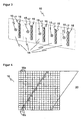
- FIG. 3 illustrates the internal structure of the multilevel sensor 10 in a view obliquely from the front.
- Each area sensor 14, of which the multilevel sensor 10 is constructed has a lighting 15 and an image sensor 16 with an associated optical system 17.
- the light source in the illumination 15 is a laser or an LED.
- a series of LEDs or a laser stack may also be provided.
- the light can also be pulled apart into the plane 20 by means of a diffractive optical element.
- the illumination 15 emits visible, ultraviolet or infrared light. In this case, visible light has the advantage that the monitored plane 20 can be recognized by operating personnel, whereas infrared or ultraviolet light does not disturb operators who work in the monitoring area 12.
- the image sensor 16 is a CCD or CMOS chip lying in the plane 20 in a line. If the viewing angle of the area sensor 14 is, for example, 90 °, this line is at a 45 ° angle, that is to say generally below half the viewing angle, in the plane 20.
- the image sensor 16 has a multiplicity of light-receiving elements arranged side by side depict the plane 20 in a line-shaped pixel image.
- a double image sensor for stereoscopic recording of the plane 20 can be understood.
- two line-shaped image sensors are adjacent to each other in the plane 20, thus taking them at a different angle and together form the image sensor 16.
- the stereoscopic image of the plane 20, which then record the two image sensors can be evaluated in this embodiment as a distance-resolved image. Further below, other alternative methods of determining distance will be described.
- the image sensor 16 can be made directly as a line-shaped, preferably integrated, chip.
- FIG. 4 shows an alternative with a matrix-shaped chip as an image sensor 16.
- a matrix-shaped image sensor 16 it is possible to use such a matrix-shaped image sensor 16 not only a plane 20, but to consider a slice of finite thickness of the monitoring area 12. But it can also, as now based on the FIG. 4 is to be explained, only one line of the matrix-shaped image sensor 16 to be active, so that the remaining light receiving elements 16a or pixels remain unused during operation. Since the production method for a line-shaped and a matrix-shaped chip is almost identical, a picture sensor 16 having a plurality of lines instead of a single line is hardly incurring higher costs.
- the image sensor 16 is illuminated in its receiving plane 20. Thus, it can be determined which light receiving elements 16b lie in the plane 20. Because this line in the FIG. 4 represented can take a rather irregular course over the matrix of the image sensor 16 and thus makes the evaluation more difficult, an adjustment process could ensure at least a right-angled position of the image sensor 16. This is relatively easy to accomplish because the image sensors 16 within the multilevel sensor 10 are aligned accordingly and a rectangular position of the multilevel sensor 10 is ensured to the plane 20 by a correspondingly regular housing of the multi-level sensor 10. After such a rough adjustment, the active light receiving elements 16b are located in a row or a column of the matrix-shaped chip. Instead of selecting a single line, the selection of several adjacent lines for monitoring level 20 is also conceivable.
- the light-receiving elements of the image sensor 16 can determine colored image values, gray values and / or distance signals. A method for determining distance will be described below in connection with FIGS. 6 and 7 described. In the case of distance determination, the necessary evaluation, for example in the form of an ASIC, can be assigned directly to the individual light-receiving element ("intelligent pixels").
- FIG. 5a an image sensor 16 is shown, which is associated with a lens 17 as optics.
- the solid and the dashed lines show, on which light receiving element or pixel receives light from different directions.
- the lens has a fairly large capture area and therefore emits a relatively large amount of light to the pixels onto which it images.
- a common lens 17 has a good energy balance and thus brightness resolution.
- a micro-optics 17 (“compound eye”) is assigned to the image sensor 16. Again, the solid or dashed lines indicate the respective capture range. Each lens of the micro-optics 17 passes less light than in the case of the common lens, so that the brightness resolution is slightly worse.
- the advantage of a micro-optic 17 is that it can be set much closer to the image sensor 16 and is also smaller in itself. This is a much more compact design possible.
- the optics 17 may be made of glass. But it can also be cast from plastic and made directly with the associated image sensor 16 as a module.
- the modules of the image sensors 16 with their associated optics 17 and optionally the lighting 15 may be mounted on a common rack or a circuit board. If a common power supply is then also provided for all modules, then this board, when used in a suitable housing, already represents the entire multilevel sensor 10.
- the modules 16, 17 are preferably assigned a common control.
- the common control can summarize an object detection of several image sensors 16 in different planes 20 and thus classify objects as dangerous or harmless ("intelligent muting").
- an object could be non-hazardous that breaks through planes 20 in a known manner, such as a moving pallet.
- the location of objects to each other can be evaluated and operators at his workplace in addition to a robot at a known distance be safe, but classified at decreasing distance as dangerous (“cooperative workstation").
- a color or gray scale image may be sufficient.
- the image sensor 16 for such embodiments of the invention may determine the distances using a light transit time method.
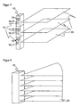
- FIG. 6 the construction of the multi-level sensor 10 with triangulating area sensors 14 is shown.
- the plane 20 to be observed is illuminated by the illumination 15 with a structured illumination pattern or a simple illumination line. This can be done for example by means of an upstream diffractive optical element or, in the case of the illumination line, as a laser line with a moving laser or a moving mirror (rad).
- the image sensor 16 is offset from the illumination 15 and placed obliquely.
- the positions of their image imaged by the optics 17 on the image sensor 16 is distance-dependent: the further away the remitting object is (ie the further to the right in FIG FIG. 6 ), the lower the image is on the image sensor 16 (the lower in FIG. 6 ).
- the line of the image sensor 16 is in the depth direction of FIG. 6 .
- the image sensor 16 thus has a shape that forms a row in the depth direction for imaging various areas in the plane 20 and in a height direction as shown in FIG FIG. 6 has one or more light-receiving elements for the triangulation.
- the height direction in each case a plurality of pixels or, for example, a differential photodiode can be used.
- a 180 ° viewing angle is provided for the triangulation in one embodiment of the invention.
- the distances, as now based on the FIG. 7 be determined with a light transit time method.
- the structure is so far inverse to that in the triangulation, as now the image sensors 16 are in the observed plane 20 and the illuminations 15, however, offset above or below or are arranged coplanar.
- time-of-flight procedures are known per se.
- the distance can be measured on the one hand over the duration of a light pulse or alternatively on the phase position of intensity-modulated light.
- a controller not shown, emits a light pulse by means of the illumination 15 and determines the transit time until it is received in the image sensor 16 and from it about the speed of light the distances.
- the illumination 15 emits intensity-modulated light of a known phase position and, via the phase shift on reception in the image sensor 16, determines the distances modulo the phase.
- FIG. 8 a multi-level sensor is shown whose levels are considered only up to a minimum distance.
- circle segments emerge as monitored planes 20. It is clear that such boundaries can be varied from plane to plane and also angle-dependent within a plane.
- monitoring areas 12 of almost any geometry can be generated, such as cones, cylinders, cuboids, cubes and more. Since the viewing angle is usually not 360 °, not necessarily cone and cylinder, but only part cone and part cylinder arise as the corresponding segments within the viewing angle.
- FIG. 9 It will be explained how distance conditions not only determine the outer boundary of the monitoring area 12, but also allow differentiations within the space area 12. Shown is an area sensor 14 with the associated observed plane 20 in plan view. In this level 20, a warning area 20a and a protection area 20b are defined. This serves to allow the multilevel sensor 10 to accept object engagement in the space area 12 as long as the warning area 20a or the protection area 20b is not damaged. If an object enters the warning area 20a, the multilevel sensor 10 reacts with a first escalation level, which may be, for example, a simple warning signal such as a sound or an alarm.
- a first escalation level which may be, for example, a simple warning signal such as a sound or an alarm.
- the multi-level sensor 10 reacts by eliminating a source of danger, for example switching off a dangerous machine.
- One of the purposes of this two-stage system is to reduce dead times caused by shutdown machines by alerting operating personnel in good time.
- the multilevel sensor 10 thus knows at which distance an object is located in the warning area 20a or in the protection area 20b.
- the spacing conditions also allow for blanking areas, such as locations where an object, such as a pallet or a measuring head, is allowed to enter without being objectionable.
- blanking areas can even be dynamic, that is, the distances are time-dependent or depend on previously detected objects. In this way, slow-moving objects or objects that are far from operating personnel can be detected as safe.
- FIG. 10a and 10b show a further variant of the invention.
- the surface sensors 14 have a viewing angle of 90 °. Of course, this does not have to be the case, but it is suitable for a cubic surveillance area 12 and a larger viewing angle is technically feasible only with increased effort.
- a plurality of image sensors 16 or the associated area sensors 14 are arranged next to one another so that their viewing angles add up. In a joint evaluation then effectively creates an area sensor 14 with a larger viewing angle.
- FIG. 10a shows an area sensor with an effective viewing angle of 180 ° from two area sensors 14
- FIG. 10b an area sensor with an effective viewing angle of 360 ° from four area sensors 14.
- FIG. 11a shows an embodiment of the invention, in which, although the surface sensors 14 lie on a common line, the planes 20 but fan-shaped apart.
- the plane spacing here depends on the distance to the multilevel sensor 10.
- a safety class that is to say a guaranteed maximum distance between the planes 20, is then fulfilled only up to a certain distance from the multilevel sensor 10. The advantage is that large obstacles can be detected earlier at a greater distance and the fineness of the object recognition then increases with increasing proximity.
- FIG. 11b shows an arrangement with mutually parading levels 20, but in which the surface sensors 14 are not arranged on a straight line, but a curve.
- the multilevel sensor 10 can cling to a curved surface and thus serve, for example, on a vehicle for collision protection ("electro-optical bumper").
- FIG. 11c shows a mixed form, in which the surface sensors 14 lie on a curve and the planes 20 run apart in a fan shape. This can be used on a vehicle to detect large-scale obstacles already at a great distance.
- FIG. 12 shows a particular embodiment of the invention, by means of which a dangerous machine such as a press brake 50 can be protected.
- a dangerous machine such as a press brake 50
- the inner portion 50a of the press brake 50 would have to be protected by a plurality of light grids respectively disposed at the corners of the inner portion 50a.
- a multilevel sensor 10 is provided, the planes 20 of which are set so that a total of a kind of cage results as a protective field.
- the big advantage of this arrangement is that the entire inner area 50a is free of hindering sensor components.
- monitoring can also be performed when bending boxes with side walls.
- the cage-like construction of the protection zone can be applied accordingly to other external geometries.
- FIG. 13 shows a further embodiment with vertically arranged planes 20 on a vehicle 60 (AGV, Automated Guided Vehicle).
- the surface sensors 14 advantageously have a viewing angle of 180 °.
- the resulting multilevel sensor 10 is therefore also suitable as a replacement for a mechanical bumper and detects a three-dimensional area in front of the vehicle.
- the area sensor such as a laser scanner
- FIG. 14 shows a further embodiment of the invention for measuring objects.
- the height of an object 70 may be determined by interrupting one or more planes 20.
- the other dimensions can be determined at least partially from the distances.
- Conventionally spatially upstream and thus disturbing light grids are used for a measurement of objects, for example, in front of a vertical circulation rack.
- cooperative boundaries of the surveillance area 12 may be provided. Particularly suitable for this are reflectors or contrast patterns. As long as their image or distance is correctly recognized in the image sensors 16, the image sensors 16 can be considered functional. If the multilevel sensor 10 monitors a free surveillance area 12, it would not be possible to verify if the surveillance area 12 is still free or the image sensor 16 is defective without such cooperative limitations.
Claims (28)
- Capteur optoélectronique (10) pour la détection d'objets dans une zone de surveillance tridimensionnelle (12) comprenant au moins un capteur d'images (16) qui, au moyen d'une pluralité d'éléments récepteurs de lumière, est capable de prendre une image en pixels de la zone de surveillance (12), et comprenant au moins une commande qui est réalisée pour la détermination d'un objet à partir des données image de l'image en pixels, dans lequel est prévue une pluralité de capteurs d'images (16) qui comprennent chacun au moins une ligne de pixels avec des éléments récepteurs de lumière (16b), de telle manière que les capteurs d'images (16) sont agencés à distance les uns des autres de façon que chaque capteur d'images (16) est capable de prendre une image d'un propre plan (20) de la zone de surveillance (12), caractérisé en ce que
la commande est réalisée pour délivrer un signal de coupure à une machine dans la zone de surveillance (12) s'il y a violation d'une zone de protection,
dans lequel les capteurs d'images (16) sont agencés de telle manière que les plans (20) sont sans chevauchement les uns par rapport aux autres et sont sensiblement parallèles les uns aux autres ou bien divergents les uns par rapport aux autres en éventail en partant des capteurs d'images (16), et
en ce que deux plans parallèles respectifs (20) sont écartés l'un de l'autre au maximum d'une distance respective prédéterminée (22) ou respectivement que deux plans respectivement divergents en éventail sont écartés, jusqu'à un éloignement prédéterminé depuis le capteur, au maximum de la distance prédéterminée, afin de satisfaire à une classe de sécurité,
dans lequel la distance prédéterminée (22) s'élève de 7 à 10 mm pour la détection de doigts, de 10 à 20 mm pour la détection d'extrémités ou de 30 à 80 mm pour la détection des extrémités inférieures d'un corps humain. - Capteur (10) selon la revendication 1, dans lequel les capteurs d'images (16) sont agencés en une rangée sur une droite ou sur une courbe.
- Capteur (10) selon la revendication 1 ou 2, dans lequel une source de lumière (15) est associée à chaque capteur d'images (16), en particulier un laser ou une diode électroluminescente.
- Capteur (10) selon la revendication 3, dans lequel la source de lumière (15) est une source de lumière pour de la lumière visible, infrarouge ou ultraviolette.
- Capteur (10) selon l'une des revendications précédentes, dans lequel les capteurs d'images (16) sont capables de prendre une image en pixels à résolution d'éloignement.
- Capteur (10) selon la revendication 3 ou 4 et 5, dans lequel la source de lumière (15) est réalisée pour illuminer, dans le plan (20) du capteur d'image associée (16), un motif d'éclairage structuré ou une ligne d'éclairage, en particulier au moyen d'un élément optique à diffraction introduit dans le trajet des rayons de la source de lumière (15), et dans lequel le capteur d'images (16) peut déterminer les éloignements au moyen d'une triangulation.
- Capteur (10) selon la revendication 3 ou 4 et 5, dans lequel les éléments récepteurs de lumière des capteurs d'images (16) peuvent déterminer les éloignements selon une procédure de temps de parcours de la lumière.
- Capteur (10) selon la revendication 7, dans lequel les sources de lumière (15) émettent des impulsions de lumière et les éléments de réception de lumière peuvent déterminer le temps de parcours des impulsions.
- Capteur (10) selon la revendication 7, dans lequel les sources de lumière (15) émettent une lumière modulée en intensité, et les éléments récepteurs de lumière peuvent déterminer son décalage de phase.
- Capteur (10) selon l'une des revendications 5 à 9, dans lequel le capteur (10) est réalisé pour la surveillance d'une zone de protection (20b) qui est une région partielle de la zone de surveillance (12), en ce que la commande attribue à chaque plan (20) des conditions de distance vis-à-vis de la zone de protection (30a-30e) avec fonction angulaire, et reconnaît un objet détecté comme une violation de la zone de protection (20b) s'il satisfait les conditions de distance vis-à-vis de la zone de protection (30a-30e).
- Capteur (10) selon la revendication 10, dans lequel le capteur (10) est réalisé pour la surveillance d'une zone d'avertissement (20a) qui englobe, à titre de zone partielle de la zone de surveillance (12), la zone de protection (20b), en ce que la commande attribue à chaque plan (20) des conditions de distance vis-à-vis de la zone d'avertissement (30a-30e) avec fonction angulaire, et reconnaît un objet détecté comme une violation de la zone d'avertissement (20a) s'il satisfait les conditions de distance vis-à-vis de la zone d'avertissement (30a-30e).
- Capteur (10) selon la revendication 10 ou 11, dans lequel les conditions de distance (30a-30e) vis-à-vis de la zone de protection ou les conditions de distance (30a-30e) vis-à-vis de la zone d'avertissement sont égales, dans plusieurs plans ou dans tous les plans (20), dans au moins une plage angulaire.
- Capteur (10) selon la revendication 10 ou 11, dans lequel la zone de protection (20a) ou la zone d'avertissement (20a) est un parallélépipède, un cube, un tronc de cône, un tronc de cylindre ou une cage en forme de parallélépipède, de cube, de tronc de cône ou de tronc de cylindre.
- Capteur (10) selon l'une des revendications précédentes, dans lequel chaque capteur d'images (16) possède un angle de vision de 90°
- Capteur (10) selon l'une des revendications précédentes, dans lequel au moins un autre capteur d'images associé (16) est agencé à côté de chaque capteur d'images (16) de telle façon que les angles de vision des capteurs d'images (16) mutuellement associés s'additionnent.
- Capteur (10) selon l'une des revendications précédentes, dans lequel chaque capteur d'images (16) comprend une puce à CCD ou une puce CMOS avec plusieurs lignes et, dans une phase d'apprentissage pour simplifier l'ajustement, il est possible de choisir pour le fonctionnement la ligne (16b) ou les lignes qui surveille(nt) le plan associé (20).
- Capteur (10) selon l'une des revendications précédentes, dans lequel une optique commune (17) est associée aux éléments récepteurs de lumière de chaque capteur d'image (16).
- Capteur (10) selon l'une des revendications précédentes, dans lequel une microoptique (17) est associée à des groupes d'éléments récepteurs de lumière de chaque capteur d'images (16), et dans lequel le capteur d'images (16) et les microoptiques (17) forment, à titre d'éléments constitutifs, un module commun.
- Capteur (10) selon l'une des revendications précédentes, dans lequel plusieurs capteurs d'images (16) ou plusieurs modules communs sont agencés sur un support de groupe structurel commun.
- Capteur (10) selon l'une des revendications précédentes, dans lequel la commande, les capteurs d'images (16) et les sources de lumière (15) comportent une alimentation en énergie commune.
- Capteur (10) selon l'une des revendications précédentes, dans lequel il est prévu une commande commune pour plusieurs capteurs d'images ou pour tous les capteurs d'images (16).
- Capteur (10) selon la revendication 21, dans lequel la commande commune est réalisée pour regrouper une détection d'objets par plusieurs capteurs d'images (16) dans des plans différents (20) pour donner une classification d'objet géométrique et pour évaluer comme une menace uniquement certaines classes d'objets.
- Capteur (10) selon la revendication 21 ou 22, dans lequel la commande commune est réalisée pour regrouper des détections d'objets par plusieurs capteurs d'images (16) pour une classification de la position d'objets les uns par rapport aux autres ainsi que leurs modifications temporelles à titre de déplacement, et pour évaluer comme une menace certaines positions d'objets ou déplacements.
- Capteur (10) selon l'une des revendications précédentes, dans lequel sont prévues des limitations coopératives de la zone de surveillance (12), et la commande est réalisée pour comparer leur image ou leur éloignement avec une image de référence ou avec des éloignements de référence, à titre de test fonctionnel des capteurs d'images (16).
- Capteur selon la revendication 11 pour la sécurisation d'une zone à risque, dans lequel la commande est réalisée pour délivrer un signal d'avertissement s'il y a violation de la zone de surveillance (20a).
- Capteur selon l'une des revendications précédentes pour l'utilisation mobile sur un véhicule (70) ou sur un robot.
- Capteur selon l'une des revendications précédentes pour l'utilisation lors de la mesure d'objets (70) dans la zone de surveillance (12).
- Procédé pour la détection d'objets dans une zone de surveillance tridimensionnelle (12) avec au moins un capteur d'images (16) qui prend une image en pixels de la zone de surveillance (12), dans lequel l'objet est détecté au moyen d'une évaluation des données image de l'image en pixels, dans lequel on prend une image d'une pluralité de plans (12) de la zone de surveillance (12) respectivement avec un capteur d'images (16) d'une pluralité de capteurs d'images (16), et les plans (20) sont écartés les uns des autres, au moins dans la région dans laquelle sont situés les capteurs d'images (16) respectifs,
caractérisé en ce que l'on délivre un signal de coupure à une machine dans la zone de surveillance quand il y a violation d'une zone de protection, les plans (20) étant sans chevauchement les uns par rapport aux autres et étant sensiblement parallèles les uns aux autres ou divergeant les uns des autres en éventail en partant des capteurs d'images (16), et deux plans parallèles respectifs (20) sont écartés l'un de l'autre au maximum d'une distance respective prédéterminée (22) ou bien deux plans divergents en éventail sont écartés, jusqu'à un éloignement prédéterminé depuis le capteur, au maximum de la distance prédéterminée, afin de satisfaire une classe de sécurité, et la distance prédéterminée (22) s'élève à 7 à 10 mm pour la détection de doigts, 10 à 20 mm pour la détection d'extrémités, ou 30 à 80 mm pour la détection des extrémités inférieures d'un corps humain.
Priority Applications (3)
| Application Number | Priority Date | Filing Date | Title |
|---|---|---|---|
| EP06024979A EP1927867B1 (fr) | 2006-12-02 | 2006-12-02 | Capteur optoélectronique à plusieurs plans et procédé de détection d'objets |
| AT06024979T ATE552514T1 (de) | 2006-12-02 | 2006-12-02 | Optoelektronischer mehrebenensensor und verfahren zur erfassung von objekten |
| US11/998,487 US7995836B2 (en) | 2006-12-02 | 2007-11-29 | Optoelectronic multiplane sensor and method for monitoring objects |
Applications Claiming Priority (1)
| Application Number | Priority Date | Filing Date | Title |
|---|---|---|---|
| EP06024979A EP1927867B1 (fr) | 2006-12-02 | 2006-12-02 | Capteur optoélectronique à plusieurs plans et procédé de détection d'objets |
Publications (2)
| Publication Number | Publication Date |
|---|---|
| EP1927867A1 EP1927867A1 (fr) | 2008-06-04 |
| EP1927867B1 true EP1927867B1 (fr) | 2012-04-04 |
Family
ID=37907680
Family Applications (1)
| Application Number | Title | Priority Date | Filing Date |
|---|---|---|---|
| EP06024979A Active EP1927867B1 (fr) | 2006-12-02 | 2006-12-02 | Capteur optoélectronique à plusieurs plans et procédé de détection d'objets |
Country Status (3)
| Country | Link |
|---|---|
| US (1) | US7995836B2 (fr) |
| EP (1) | EP1927867B1 (fr) |
| AT (1) | ATE552514T1 (fr) |
Cited By (7)
| Publication number | Priority date | Publication date | Assignee | Title |
|---|---|---|---|---|
| DE102014106854A1 (de) * | 2014-05-15 | 2016-01-28 | Odos Imaging Ltd. | Bildgebendes System und Verfahren zum Überwachen eines Sichtfeldes |
| EP3182160A1 (fr) | 2015-12-15 | 2017-06-21 | Sick Ag | Capteur optoélectronique et procédé de détection d'un objet |
| DE202017103345U1 (de) | 2017-06-02 | 2018-09-05 | Sick Ag | Tastendes Lichtgitter zur Erfassung von Objekten |
| EP3832344A1 (fr) | 2019-12-05 | 2021-06-09 | Sick Ag | Capteur optoélectronique et procédé de détection d'un objet |
| DE202021104253U1 (de) | 2021-08-09 | 2022-11-11 | Sick Ag | Strahlteileranordnung für einen optoelektronischen Sensor und optoelektronischer Sensor mit einer solchen |
| EP4109127A1 (fr) | 2021-06-21 | 2022-12-28 | Sick Ag | Capteur optoélectronique et procédé de détection des objets |
| DE102021120698A1 (de) | 2021-08-09 | 2023-02-09 | Sick Ag | Strahlteileranordnung für einen optoelektronischen Sensor, optoelektronischer Sensor mit einer solchen und Verfahren zur Strahlteilung in einem optoelektronischen Sensor |
Families Citing this family (32)
| Publication number | Priority date | Publication date | Assignee | Title |
|---|---|---|---|---|
| DE202006008112U1 (de) * | 2006-05-20 | 2006-08-10 | Sick Ag | Optoelektronische Schutzeinrichtung |
| USRE46672E1 (en) | 2006-07-13 | 2018-01-16 | Velodyne Lidar, Inc. | High definition LiDAR system |
| DE102007043378B4 (de) * | 2007-09-12 | 2010-04-29 | Leuze Electronic Gmbh & Co Kg | Lichtgitter |
| DE202008016946U1 (de) * | 2008-12-20 | 2010-05-27 | Sick Ag | Lichtgitter oder Lichtschranke |
| DE102009045600B4 (de) | 2009-10-12 | 2021-11-04 | pmdtechnologies ag | Kamerasystem |
| DE102010009590A1 (de) * | 2010-02-26 | 2011-09-01 | Rheinisch-Westfälische Technische Hochschule Aachen | Sensorsystem und Verfahren zur Überwachung eines Raumes |
| EP2667218B1 (fr) * | 2010-11-15 | 2017-10-18 | Cedes AG | Capteur 3D à économie d'énergie |
| DE202011005059U1 (de) * | 2011-04-08 | 2011-08-11 | Leuze Electronic Gmbh + Co. Kg | Optischer Sensor |
| DE102013100522A1 (de) * | 2013-01-18 | 2014-08-07 | Huf Hülsbeck & Fürst Gmbh & Co. Kg | Universelle Sensoranordnung zur Erfassung von Bediengesten an Fahrzeugen |
| DE102013100521A1 (de) * | 2013-01-18 | 2014-07-24 | Huf Hülsbeck & Fürst Gmbh & Co. Kg | Sensoranordnung zur Erfassung von Bediengesten an Fahrzeugen |
| US9545582B2 (en) * | 2013-08-23 | 2017-01-17 | Evollve, Inc. | Robotic activity system using color patterns |
| DE102014204423B4 (de) * | 2014-03-11 | 2021-06-02 | pmdtechnologies ag | Lichtlaufzeitkamerasystem |
| EP3081960B1 (fr) * | 2015-04-13 | 2023-03-22 | Rockwell Automation Switzerland GmbH | Barrière photoélectrique de sécurité à temps de vol et procédé de surveillance d'un champ de protection |
| DE102015121840A1 (de) * | 2015-12-15 | 2017-06-22 | Sick Ag | Optoelektronischer Sensor und Verfahren zur Erfassung eines Objekts |
| US20180365550A1 (en) * | 2016-01-11 | 2018-12-20 | Flow Lighting, Llc | Systems, and methods for detecting, counting, and tracking people and assets |
| US10627490B2 (en) | 2016-01-31 | 2020-04-21 | Velodyne Lidar, Inc. | Multiple pulse, LIDAR based 3-D imaging |
| DE102016103028A1 (de) * | 2016-02-22 | 2017-08-24 | Sick Ag | Vorrichtung zum Überwachen eines Überwachungsbereichs |
| WO2017164989A1 (fr) | 2016-03-19 | 2017-09-28 | Velodyne Lidar, Inc. | Éclairage et détection intégrés pour imagerie 3d basée sur lidar |
| JP7165587B2 (ja) | 2016-06-01 | 2022-11-04 | ベロダイン ライダー ユーエスエー,インコーポレイテッド | 多重ピクセル走査lidar |
| EP3455110A4 (fr) * | 2016-12-05 | 2019-05-29 | Shenzhen Goodix Technology Co., Ltd. | Détection de positions de véhicule avec des capteurs optiques |
| CN108398692A (zh) * | 2017-02-06 | 2018-08-14 | 罗伯团队家居有限公司 | 光检测和测距装置 |
| US10365351B2 (en) * | 2017-03-17 | 2019-07-30 | Waymo Llc | Variable beam spacing, timing, and power for vehicle sensors |
| EP3593166B1 (fr) | 2017-03-31 | 2024-04-17 | Velodyne Lidar USA, Inc. | Commande de puissance d'éclairage à lidar intégré |
| CN115575928A (zh) | 2017-05-08 | 2023-01-06 | 威力登激光雷达美国有限公司 | Lidar数据获取与控制 |
| EP3525004B1 (fr) | 2018-02-08 | 2020-10-14 | Cedes AG | Capteur tof pourvu d'émetteur de contrôle |
| JP6572338B1 (ja) * | 2018-03-14 | 2019-09-04 | 株式会社アマダホールディングス | プレスブレーキ用光学式安全装置、プレスブレーキ、及び光学式監視方法 |
| DE202018103537U1 (de) * | 2018-06-22 | 2019-10-02 | Leuze Electronic Gmbh + Co. Kg | Optischer Sensor |
| DE102018122263B4 (de) * | 2018-09-12 | 2021-03-18 | Sick Ag | Autonomes Fahrzeug |
| US11082010B2 (en) | 2018-11-06 | 2021-08-03 | Velodyne Lidar Usa, Inc. | Systems and methods for TIA base current detection and compensation |
| US11885958B2 (en) | 2019-01-07 | 2024-01-30 | Velodyne Lidar Usa, Inc. | Systems and methods for a dual axis resonant scanning mirror |
| US11556000B1 (en) | 2019-08-22 | 2023-01-17 | Red Creamery Llc | Distally-actuated scanning mirror |
| AT17459U1 (de) * | 2021-01-21 | 2022-05-15 | Altendorf Gmbh | Sicherheitseinrichtung für Werkzeugmaschinen |
Family Cites Families (21)
| Publication number | Priority date | Publication date | Assignee | Title |
|---|---|---|---|---|
| DE2818942C2 (de) | 1978-04-28 | 1986-03-27 | Zellweger Uster Ag, Uster | Verfahren zur Raumüberwachung und Vorrichtung zur Durchführung des Verfahrens |
| US7164117B2 (en) * | 1992-05-05 | 2007-01-16 | Automotive Technologies International, Inc. | Vehicular restraint system control system and method using multiple optical imagers |
| US6856873B2 (en) * | 1995-06-07 | 2005-02-15 | Automotive Technologies International, Inc. | Vehicular monitoring systems using image processing |
| JPS6479712A (en) * | 1987-09-21 | 1989-03-24 | Fuji Photo Film Co Ltd | Automatic focusing adjuster |
| US5004997A (en) * | 1990-01-22 | 1991-04-02 | Insys Ltd. | Parking aid device |
| DE59710276D1 (de) * | 1997-10-31 | 2003-07-17 | Laser Applikationan Gmbh | Verfahren zur berührungsfreien Messung des Abstands eines Objekts nach dem Prinzip der Laser-Triangulation |
| DE19757848C2 (de) | 1997-12-24 | 2003-04-30 | Sick Ag | Vorrichtung zur optischen Erfassung von Objekten |
| DE19815149A1 (de) * | 1998-04-03 | 1999-10-07 | Leuze Electronic Gmbh & Co | Sensoranordnung |
| US6441363B1 (en) | 1999-02-24 | 2002-08-27 | Siemens Vdo Automotive Corporation | Vehicle occupant sensing system |
| DE19919925C2 (de) | 1999-04-30 | 2001-06-13 | Siemens Ag | Anordnung und Verfahren zur gleichzeitigen Messung der Geschwindigkeit sowie der Oberflächengestalt von bewegten Objekten |
| US6297844B1 (en) | 1999-11-24 | 2001-10-02 | Cognex Corporation | Video safety curtain |
| EP1174733B1 (fr) | 2000-07-21 | 2005-02-02 | Leuze electronic GmbH + Co KG | Capteur optique |
| DE10110420A1 (de) | 2001-03-05 | 2002-09-12 | Sick Ag | Vorrichtung zur Bestimmung eines Abstandsprofils |
| CN1613020A (zh) * | 2001-11-08 | 2005-05-04 | 西门子公司 | 用于测量距离的激光光栅 |
| DE10229408B4 (de) | 2002-06-29 | 2006-09-07 | Leuze Electronic Gmbh & Co Kg | Optischer Sensor |
| US20040066500A1 (en) * | 2002-10-02 | 2004-04-08 | Gokturk Salih Burak | Occupancy detection and measurement system and method |
| DE10360789B4 (de) | 2003-12-23 | 2007-03-15 | Leuze Lumiflex Gmbh + Co. Kg | Vorrichtung zur Überwachung eines Erfassungsbereichs an einem Arbeitsmittel |
| DE102005050824A1 (de) | 2004-11-17 | 2006-05-24 | Heidelberger Druckmaschinen Ag | Verfahren zur ortsabhängigen Absicherung von gefährlichen Bereichen |
| DE102005003827B4 (de) | 2005-01-26 | 2007-01-04 | Fraunhofer-Gesellschaft zur Förderung der angewandten Forschung e.V. | Vorrichtung und Verfahren zur Interaktion zwischen einem Menschen und einer Robotereinheit an einem Roboterarbeitsplatz |
| JP4764070B2 (ja) | 2005-05-24 | 2011-08-31 | 本田技研工業株式会社 | 作業ステーションの安全システム |
| DE202006012351U1 (de) | 2006-02-25 | 2006-10-19 | Leuze Lumiflex Gmbh + Co. Kg | Optischer Sensor zur Überwachung einer Schutzzone |
-
2006
- 2006-12-02 EP EP06024979A patent/EP1927867B1/fr active Active
- 2006-12-02 AT AT06024979T patent/ATE552514T1/de active
-
2007
- 2007-11-29 US US11/998,487 patent/US7995836B2/en not_active Expired - Fee Related
Cited By (9)
| Publication number | Priority date | Publication date | Assignee | Title |
|---|---|---|---|---|
| DE102014106854A1 (de) * | 2014-05-15 | 2016-01-28 | Odos Imaging Ltd. | Bildgebendes System und Verfahren zum Überwachen eines Sichtfeldes |
| EP3182160A1 (fr) | 2015-12-15 | 2017-06-21 | Sick Ag | Capteur optoélectronique et procédé de détection d'un objet |
| DE102015121839A1 (de) | 2015-12-15 | 2017-06-22 | Sick Ag | Optoelektronischer Sensor und Verfahren zur Erfassung eines Objekts |
| DE202017103345U1 (de) | 2017-06-02 | 2018-09-05 | Sick Ag | Tastendes Lichtgitter zur Erfassung von Objekten |
| EP3832344A1 (fr) | 2019-12-05 | 2021-06-09 | Sick Ag | Capteur optoélectronique et procédé de détection d'un objet |
| EP4109127A1 (fr) | 2021-06-21 | 2022-12-28 | Sick Ag | Capteur optoélectronique et procédé de détection des objets |
| DE202021104253U1 (de) | 2021-08-09 | 2022-11-11 | Sick Ag | Strahlteileranordnung für einen optoelektronischen Sensor und optoelektronischer Sensor mit einer solchen |
| DE102021120698A1 (de) | 2021-08-09 | 2023-02-09 | Sick Ag | Strahlteileranordnung für einen optoelektronischen Sensor, optoelektronischer Sensor mit einer solchen und Verfahren zur Strahlteilung in einem optoelektronischen Sensor |
| EP4134702A1 (fr) | 2021-08-09 | 2023-02-15 | Sick Ag | Dispositif diviseur de faisceau pour un capteur optoélectronique, capteur optoélectronique doté d'un tel dispositif et procédé de division de faisceau dans un capteur optoélectronique |
Also Published As
| Publication number | Publication date |
|---|---|
| EP1927867A1 (fr) | 2008-06-04 |
| US20080285842A1 (en) | 2008-11-20 |
| US7995836B2 (en) | 2011-08-09 |
| ATE552514T1 (de) | 2012-04-15 |
Similar Documents
| Publication | Publication Date | Title |
|---|---|---|
| EP1927867B1 (fr) | Capteur optoélectronique à plusieurs plans et procédé de détection d'objets | |
| DE102009031732B3 (de) | Entfernungsmessender optoelektronischer Sensor | |
| EP2541273B1 (fr) | Détection et détermination de distance d'objets | |
| DE19938639B4 (de) | Vorrichtung zur Absicherung eines Gefahrenbereichs, insbesondere des Gefahrenbereichs einer automatisiert arbeitenden Maschine | |
| EP1723446B1 (fr) | Dispositif de controle d'acces | |
| EP2667218B1 (fr) | Capteur 3D à économie d'énergie | |
| EP2434432A1 (fr) | Contrôle en boucle fermée de l'intensité d'illumination pour un capteur optoélectronique | |
| EP2202994B1 (fr) | Caméra 3D pour la surveillance de pièces | |
| EP1544535A1 (fr) | Dispositif de surveillance de la zone dans la portée d'un outil de travail | |
| EP3078985B1 (fr) | Capteur optoelectronique et procede de surveillance de transmission d'un disque frontal | |
| EP1068992A2 (fr) | Aide pour reculer | |
| EP2881762B1 (fr) | Capteur optoélectrique et procédé de détection d'objets brillants | |
| DE102009034848B4 (de) | Optoelektronischer Sensor | |
| DE10033608A1 (de) | Verfahren und Vorrichtung zum Absichern eines Gefahrenbereichs, insbesondere des Gefahrenbereichs einer automatisiert arbeitenden Maschine | |
| DE10327388B4 (de) | Schutzeinrichtung | |
| EP1857838B1 (fr) | Dispositif de protection optoélectrique | |
| DE102016110514B4 (de) | Vorrichtung und Verfahren zum Überwachen eines Raumbereichs, insbesondere zum Absichern eines Gefahrenbereichs einer automatisiert arbeitenden Anlage | |
| DE102018121144B3 (de) | Verfahren und Vorrichtung zum Überprüfen der Einstellung von Scheinwerfern von Kraftfahrzeugen | |
| DE102013007961B4 (de) | Optisches Messsystem für ein Fahrzeug | |
| DE102004026090A1 (de) | Messsystem zur dreidimensionalen Bilderfassung | |
| DE3840677A1 (de) | Optischer ueberwachungssensor | |
| EP3502614B1 (fr) | Dispositif de mesure optique | |
| DE202007014313U1 (de) | Optoelektronische Schutzeinrichtung | |
| DE10142362A1 (de) | Optoelekronische Überwachungseinrichtung | |
| DE19964492B4 (de) | Vorrichtung zur Absicherung eines Gefahrenbereichs, insbesondere des Gefahrenbereichs einer automatisiert arbeitenden Maschine |
Legal Events
| Date | Code | Title | Description |
|---|---|---|---|
| PUAI | Public reference made under article 153(3) epc to a published international application that has entered the european phase |
Free format text: ORIGINAL CODE: 0009012 |
|
| 17P | Request for examination filed |
Effective date: 20070611 |
|
| AK | Designated contracting states |
Kind code of ref document: A1 Designated state(s): AT BE BG CH CY CZ DE DK EE ES FI FR GB GR HU IE IS IT LI LT LU LV MC NL PL PT RO SE SI SK TR |
|
| AX | Request for extension of the european patent |
Extension state: AL BA HR MK RS |
|
| 17Q | First examination report despatched |
Effective date: 20081104 |
|
| AKX | Designation fees paid |
Designated state(s): AT BE BG CH CY CZ DE DK EE ES FI FR GB GR HU IE IS IT LI LT LU LV MC NL PL PT RO SE SI SK TR |
|
| GRAP | Despatch of communication of intention to grant a patent |
Free format text: ORIGINAL CODE: EPIDOSNIGR1 |
|
| RIC1 | Information provided on ipc code assigned before grant |
Ipc: G01S 17/87 20060101ALI20111118BHEP Ipc: G01S 17/48 20060101ALI20111118BHEP Ipc: F16P 3/14 20060101ALI20111118BHEP Ipc: G01S 17/02 20060101AFI20111118BHEP Ipc: G01S 17/42 20060101ALI20111118BHEP |
|
| GRAS | Grant fee paid |
Free format text: ORIGINAL CODE: EPIDOSNIGR3 |
|
| GRAA | (expected) grant |
Free format text: ORIGINAL CODE: 0009210 |
|
| AK | Designated contracting states |
Kind code of ref document: B1 Designated state(s): AT BE BG CH CY CZ DE DK EE ES FI FR GB GR HU IE IS IT LI LT LU LV MC NL PL PT RO SE SI SK TR |
|
| REG | Reference to a national code |
Ref country code: GB Ref legal event code: FG4D Free format text: NOT ENGLISH |
|
| REG | Reference to a national code |
Ref country code: CH Ref legal event code: EP |
|
| REG | Reference to a national code |
Ref country code: AT Ref legal event code: REF Ref document number: 552514 Country of ref document: AT Kind code of ref document: T Effective date: 20120415 |
|
| REG | Reference to a national code |
Ref country code: IE Ref legal event code: FG4D Free format text: LANGUAGE OF EP DOCUMENT: GERMAN |
|
| REG | Reference to a national code |
Ref country code: DE Ref legal event code: R096 Ref document number: 502006011233 Country of ref document: DE Effective date: 20120524 |
|
| REG | Reference to a national code |
Ref country code: NL Ref legal event code: VDEP Effective date: 20120404 |
|
| LTIE | Lt: invalidation of european patent or patent extension |
Effective date: 20120404 |
|
| PG25 | Lapsed in a contracting state [announced via postgrant information from national office to epo] |
Ref country code: LT Free format text: LAPSE BECAUSE OF FAILURE TO SUBMIT A TRANSLATION OF THE DESCRIPTION OR TO PAY THE FEE WITHIN THE PRESCRIBED TIME-LIMIT Effective date: 20120404 Ref country code: PL Free format text: LAPSE BECAUSE OF FAILURE TO SUBMIT A TRANSLATION OF THE DESCRIPTION OR TO PAY THE FEE WITHIN THE PRESCRIBED TIME-LIMIT Effective date: 20120404 Ref country code: IS Free format text: LAPSE BECAUSE OF FAILURE TO SUBMIT A TRANSLATION OF THE DESCRIPTION OR TO PAY THE FEE WITHIN THE PRESCRIBED TIME-LIMIT Effective date: 20120804 Ref country code: FI Free format text: LAPSE BECAUSE OF FAILURE TO SUBMIT A TRANSLATION OF THE DESCRIPTION OR TO PAY THE FEE WITHIN THE PRESCRIBED TIME-LIMIT Effective date: 20120404 Ref country code: SI Free format text: LAPSE BECAUSE OF FAILURE TO SUBMIT A TRANSLATION OF THE DESCRIPTION OR TO PAY THE FEE WITHIN THE PRESCRIBED TIME-LIMIT Effective date: 20120404 Ref country code: SE Free format text: LAPSE BECAUSE OF FAILURE TO SUBMIT A TRANSLATION OF THE DESCRIPTION OR TO PAY THE FEE WITHIN THE PRESCRIBED TIME-LIMIT Effective date: 20120404 Ref country code: CY Free format text: LAPSE BECAUSE OF FAILURE TO SUBMIT A TRANSLATION OF THE DESCRIPTION OR TO PAY THE FEE WITHIN THE PRESCRIBED TIME-LIMIT Effective date: 20120404 |
|
| PG25 | Lapsed in a contracting state [announced via postgrant information from national office to epo] |
Ref country code: LV Free format text: LAPSE BECAUSE OF FAILURE TO SUBMIT A TRANSLATION OF THE DESCRIPTION OR TO PAY THE FEE WITHIN THE PRESCRIBED TIME-LIMIT Effective date: 20120404 Ref country code: GR Free format text: LAPSE BECAUSE OF FAILURE TO SUBMIT A TRANSLATION OF THE DESCRIPTION OR TO PAY THE FEE WITHIN THE PRESCRIBED TIME-LIMIT Effective date: 20120705 Ref country code: PT Free format text: LAPSE BECAUSE OF FAILURE TO SUBMIT A TRANSLATION OF THE DESCRIPTION OR TO PAY THE FEE WITHIN THE PRESCRIBED TIME-LIMIT Effective date: 20120806 |
|
| PG25 | Lapsed in a contracting state [announced via postgrant information from national office to epo] |
Ref country code: EE Free format text: LAPSE BECAUSE OF FAILURE TO SUBMIT A TRANSLATION OF THE DESCRIPTION OR TO PAY THE FEE WITHIN THE PRESCRIBED TIME-LIMIT Effective date: 20120404 Ref country code: RO Free format text: LAPSE BECAUSE OF FAILURE TO SUBMIT A TRANSLATION OF THE DESCRIPTION OR TO PAY THE FEE WITHIN THE PRESCRIBED TIME-LIMIT Effective date: 20120404 Ref country code: NL Free format text: LAPSE BECAUSE OF FAILURE TO SUBMIT A TRANSLATION OF THE DESCRIPTION OR TO PAY THE FEE WITHIN THE PRESCRIBED TIME-LIMIT Effective date: 20120404 Ref country code: DK Free format text: LAPSE BECAUSE OF FAILURE TO SUBMIT A TRANSLATION OF THE DESCRIPTION OR TO PAY THE FEE WITHIN THE PRESCRIBED TIME-LIMIT Effective date: 20120404 Ref country code: SK Free format text: LAPSE BECAUSE OF FAILURE TO SUBMIT A TRANSLATION OF THE DESCRIPTION OR TO PAY THE FEE WITHIN THE PRESCRIBED TIME-LIMIT Effective date: 20120404 Ref country code: CZ Free format text: LAPSE BECAUSE OF FAILURE TO SUBMIT A TRANSLATION OF THE DESCRIPTION OR TO PAY THE FEE WITHIN THE PRESCRIBED TIME-LIMIT Effective date: 20120404 |
|
| PLBE | No opposition filed within time limit |
Free format text: ORIGINAL CODE: 0009261 |
|
| STAA | Information on the status of an ep patent application or granted ep patent |
Free format text: STATUS: NO OPPOSITION FILED WITHIN TIME LIMIT |
|
| PG25 | Lapsed in a contracting state [announced via postgrant information from national office to epo] |
Ref country code: IT Free format text: LAPSE BECAUSE OF FAILURE TO SUBMIT A TRANSLATION OF THE DESCRIPTION OR TO PAY THE FEE WITHIN THE PRESCRIBED TIME-LIMIT Effective date: 20120404 |
|
| 26N | No opposition filed |
Effective date: 20130107 |
|
| PG25 | Lapsed in a contracting state [announced via postgrant information from national office to epo] |
Ref country code: ES Free format text: LAPSE BECAUSE OF FAILURE TO SUBMIT A TRANSLATION OF THE DESCRIPTION OR TO PAY THE FEE WITHIN THE PRESCRIBED TIME-LIMIT Effective date: 20120715 |
|
| REG | Reference to a national code |
Ref country code: DE Ref legal event code: R097 Ref document number: 502006011233 Country of ref document: DE Effective date: 20130107 |
|
| BERE | Be: lapsed |
Owner name: SICK A.G. Effective date: 20121231 |
|
| PG25 | Lapsed in a contracting state [announced via postgrant information from national office to epo] |
Ref country code: BG Free format text: LAPSE BECAUSE OF FAILURE TO SUBMIT A TRANSLATION OF THE DESCRIPTION OR TO PAY THE FEE WITHIN THE PRESCRIBED TIME-LIMIT Effective date: 20120704 Ref country code: MC Free format text: LAPSE BECAUSE OF NON-PAYMENT OF DUE FEES Effective date: 20121231 |
|
| REG | Reference to a national code |
Ref country code: IE Ref legal event code: MM4A |
|
| PG25 | Lapsed in a contracting state [announced via postgrant information from national office to epo] |
Ref country code: BE Free format text: LAPSE BECAUSE OF NON-PAYMENT OF DUE FEES Effective date: 20121231 |
|
| PG25 | Lapsed in a contracting state [announced via postgrant information from national office to epo] |
Ref country code: IE Free format text: LAPSE BECAUSE OF NON-PAYMENT OF DUE FEES Effective date: 20121202 |
|
| REG | Reference to a national code |
Ref country code: AT Ref legal event code: MM01 Ref document number: 552514 Country of ref document: AT Kind code of ref document: T Effective date: 20121202 |
|
| PG25 | Lapsed in a contracting state [announced via postgrant information from national office to epo] |
Ref country code: TR Free format text: LAPSE BECAUSE OF FAILURE TO SUBMIT A TRANSLATION OF THE DESCRIPTION OR TO PAY THE FEE WITHIN THE PRESCRIBED TIME-LIMIT Effective date: 20120404 |
|
| PG25 | Lapsed in a contracting state [announced via postgrant information from national office to epo] |
Ref country code: LU Free format text: LAPSE BECAUSE OF NON-PAYMENT OF DUE FEES Effective date: 20121202 Ref country code: AT Free format text: LAPSE BECAUSE OF NON-PAYMENT OF DUE FEES Effective date: 20121202 |
|
| PG25 | Lapsed in a contracting state [announced via postgrant information from national office to epo] |
Ref country code: HU Free format text: LAPSE BECAUSE OF FAILURE TO SUBMIT A TRANSLATION OF THE DESCRIPTION OR TO PAY THE FEE WITHIN THE PRESCRIBED TIME-LIMIT Effective date: 20061202 |
|
| PGFP | Annual fee paid to national office [announced via postgrant information from national office to epo] |
Ref country code: CH Payment date: 20141216 Year of fee payment: 9 Ref country code: GB Payment date: 20141216 Year of fee payment: 9 |
|
| PGFP | Annual fee paid to national office [announced via postgrant information from national office to epo] |
Ref country code: FR Payment date: 20141212 Year of fee payment: 9 |
|
| REG | Reference to a national code |
Ref country code: CH Ref legal event code: PL |
|
| GBPC | Gb: european patent ceased through non-payment of renewal fee |
Effective date: 20151202 |
|
| REG | Reference to a national code |
Ref country code: FR Ref legal event code: ST Effective date: 20160831 |
|
| PG25 | Lapsed in a contracting state [announced via postgrant information from national office to epo] |
Ref country code: CH Free format text: LAPSE BECAUSE OF NON-PAYMENT OF DUE FEES Effective date: 20151231 Ref country code: LI Free format text: LAPSE BECAUSE OF NON-PAYMENT OF DUE FEES Effective date: 20151231 Ref country code: GB Free format text: LAPSE BECAUSE OF NON-PAYMENT OF DUE FEES Effective date: 20151202 |
|
| PG25 | Lapsed in a contracting state [announced via postgrant information from national office to epo] |
Ref country code: FR Free format text: LAPSE BECAUSE OF NON-PAYMENT OF DUE FEES Effective date: 20151231 |
|
| PGFP | Annual fee paid to national office [announced via postgrant information from national office to epo] |
Ref country code: DE Payment date: 20231214 Year of fee payment: 18 |