EP1926567B2 - Twist drill - Google Patents
Twist drill Download PDFInfo
- Publication number
- EP1926567B2 EP1926567B2 EP06765199.2A EP06765199A EP1926567B2 EP 1926567 B2 EP1926567 B2 EP 1926567B2 EP 06765199 A EP06765199 A EP 06765199A EP 1926567 B2 EP1926567 B2 EP 1926567B2
- Authority
- EP
- European Patent Office
- Prior art keywords
- cutting portion
- cutting
- twist drill
- point
- angle
- Prior art date
- Legal status (The legal status is an assumption and is not a legal conclusion. Google has not performed a legal analysis and makes no representation as to the accuracy of the status listed.)
- Active
Links
- 238000005520 cutting process Methods 0.000 claims abstract description 259
- 230000002093 peripheral effect Effects 0.000 claims abstract description 5
- 239000000463 material Substances 0.000 claims description 39
- 239000000835 fiber Substances 0.000 claims description 24
- 238000005553 drilling Methods 0.000 claims description 22
- 229910052799 carbon Inorganic materials 0.000 claims description 20
- OKTJSMMVPCPJKN-UHFFFAOYSA-N Carbon Chemical compound [C] OKTJSMMVPCPJKN-UHFFFAOYSA-N 0.000 claims description 18
- 239000002648 laminated material Substances 0.000 claims description 16
- 229910052751 metal Inorganic materials 0.000 claims description 16
- 239000002184 metal Substances 0.000 claims description 16
- 238000000034 method Methods 0.000 claims description 16
- 229910052782 aluminium Inorganic materials 0.000 claims description 14
- 239000004411 aluminium Substances 0.000 claims description 13
- XAGFODPZIPBFFR-UHFFFAOYSA-N aluminium Chemical compound [Al] XAGFODPZIPBFFR-UHFFFAOYSA-N 0.000 claims description 12
- 239000004918 carbon fiber reinforced polymer Substances 0.000 claims description 10
- 239000002131 composite material Substances 0.000 claims description 9
- 238000004519 manufacturing process Methods 0.000 claims description 5
- 229910003460 diamond Inorganic materials 0.000 claims description 4
- 239000010432 diamond Substances 0.000 claims description 4
- 239000000758 substrate Substances 0.000 claims description 4
- UONOETXJSWQNOL-UHFFFAOYSA-N tungsten carbide Chemical compound [W+]#[C-] UONOETXJSWQNOL-UHFFFAOYSA-N 0.000 claims description 2
- 238000005555 metalworking Methods 0.000 abstract description 15
- 238000012360 testing method Methods 0.000 description 16
- 238000003754 machining Methods 0.000 description 6
- 229910000879 EN 3B Inorganic materials 0.000 description 5
- 230000032798 delamination Effects 0.000 description 5
- 229920002430 Fibre-reinforced plastic Polymers 0.000 description 4
- 229910000831 Steel Inorganic materials 0.000 description 4
- 238000000576 coating method Methods 0.000 description 4
- 239000002826 coolant Substances 0.000 description 4
- 239000010959 steel Substances 0.000 description 4
- 229910000997 High-speed steel Inorganic materials 0.000 description 3
- 230000001154 acute effect Effects 0.000 description 3
- 239000011248 coating agent Substances 0.000 description 3
- 239000011151 fibre-reinforced plastic Substances 0.000 description 3
- 230000009467 reduction Effects 0.000 description 3
- 239000010936 titanium Substances 0.000 description 3
- 230000009286 beneficial effect Effects 0.000 description 2
- 230000015572 biosynthetic process Effects 0.000 description 2
- 230000003628 erosive effect Effects 0.000 description 2
- 238000002474 experimental method Methods 0.000 description 2
- 230000006872 improvement Effects 0.000 description 2
- 238000003475 lamination Methods 0.000 description 2
- 150000002739 metals Chemical class 0.000 description 2
- 239000010935 stainless steel Substances 0.000 description 2
- 229910001220 stainless steel Inorganic materials 0.000 description 2
- 229910052719 titanium Inorganic materials 0.000 description 2
- 229910017083 AlN Inorganic materials 0.000 description 1
- PIGFYZPCRLYGLF-UHFFFAOYSA-N Aluminum nitride Chemical compound [Al]#N PIGFYZPCRLYGLF-UHFFFAOYSA-N 0.000 description 1
- 229910001369 Brass Inorganic materials 0.000 description 1
- 229910000975 Carbon steel Inorganic materials 0.000 description 1
- RYGMFSIKBFXOCR-UHFFFAOYSA-N Copper Chemical compound [Cu] RYGMFSIKBFXOCR-UHFFFAOYSA-N 0.000 description 1
- 101100172748 Mus musculus Ethe1 gene Proteins 0.000 description 1
- 229910052581 Si3N4 Inorganic materials 0.000 description 1
- ATJFFYVFTNAWJD-UHFFFAOYSA-N Tin Chemical compound [Sn] ATJFFYVFTNAWJD-UHFFFAOYSA-N 0.000 description 1
- RTAQQCXQSZGOHL-UHFFFAOYSA-N Titanium Chemical compound [Ti] RTAQQCXQSZGOHL-UHFFFAOYSA-N 0.000 description 1
- 229910045601 alloy Inorganic materials 0.000 description 1
- 239000000956 alloy Substances 0.000 description 1
- 238000013459 approach Methods 0.000 description 1
- 239000010951 brass Substances 0.000 description 1
- 238000010276 construction Methods 0.000 description 1
- 239000010949 copper Substances 0.000 description 1
- 229910052802 copper Inorganic materials 0.000 description 1
- 239000002173 cutting fluid Substances 0.000 description 1
- 230000001627 detrimental effect Effects 0.000 description 1
- 238000009826 distribution Methods 0.000 description 1
- 230000002349 favourable effect Effects 0.000 description 1
- 239000011152 fibreglass Substances 0.000 description 1
- 239000003365 glass fiber Substances 0.000 description 1
- 230000002452 interceptive effect Effects 0.000 description 1
- 239000000314 lubricant Substances 0.000 description 1
- 238000005259 measurement Methods 0.000 description 1
- 230000007246 mechanism Effects 0.000 description 1
- PXHVJJICTQNCMI-UHFFFAOYSA-N nickel Substances [Ni] PXHVJJICTQNCMI-UHFFFAOYSA-N 0.000 description 1
- 229910052759 nickel Inorganic materials 0.000 description 1
- 230000035515 penetration Effects 0.000 description 1
- 238000002407 reforming Methods 0.000 description 1
- HQVNEWCFYHHQES-UHFFFAOYSA-N silicon nitride Chemical compound N12[Si]34N5[Si]62N3[Si]51N64 HQVNEWCFYHHQES-UHFFFAOYSA-N 0.000 description 1
- 239000002699 waste material Substances 0.000 description 1
- 239000002023 wood Substances 0.000 description 1
Images
Classifications
-
- B—PERFORMING OPERATIONS; TRANSPORTING
- B23—MACHINE TOOLS; METAL-WORKING NOT OTHERWISE PROVIDED FOR
- B23B—TURNING; BORING
- B23B51/00—Tools for drilling machines
- B23B51/02—Twist drills
-
- B—PERFORMING OPERATIONS; TRANSPORTING
- B23—MACHINE TOOLS; METAL-WORKING NOT OTHERWISE PROVIDED FOR
- B23P—METAL-WORKING NOT OTHERWISE PROVIDED FOR; COMBINED OPERATIONS; UNIVERSAL MACHINE TOOLS
- B23P15/00—Making specific metal objects by operations not covered by a single other subclass or a group in this subclass
- B23P15/28—Making specific metal objects by operations not covered by a single other subclass or a group in this subclass cutting tools
- B23P15/32—Making specific metal objects by operations not covered by a single other subclass or a group in this subclass cutting tools twist-drills
-
- B—PERFORMING OPERATIONS; TRANSPORTING
- B24—GRINDING; POLISHING
- B24B—MACHINES, DEVICES, OR PROCESSES FOR GRINDING OR POLISHING; DRESSING OR CONDITIONING OF ABRADING SURFACES; FEEDING OF GRINDING, POLISHING, OR LAPPING AGENTS
- B24B3/00—Sharpening cutting edges, e.g. of tools; Accessories therefor, e.g. for holding the tools
- B24B3/24—Sharpening cutting edges, e.g. of tools; Accessories therefor, e.g. for holding the tools of drills
- B24B3/26—Sharpening cutting edges, e.g. of tools; Accessories therefor, e.g. for holding the tools of drills of the point of twist drills
-
- B—PERFORMING OPERATIONS; TRANSPORTING
- B23—MACHINE TOOLS; METAL-WORKING NOT OTHERWISE PROVIDED FOR
- B23B—TURNING; BORING
- B23B2226/00—Materials of tools or workpieces not comprising a metal
- B23B2226/27—Composites
-
- B—PERFORMING OPERATIONS; TRANSPORTING
- B23—MACHINE TOOLS; METAL-WORKING NOT OTHERWISE PROVIDED FOR
- B23B—TURNING; BORING
- B23B2250/00—Compensating adverse effects during turning, boring or drilling
- B23B2250/12—Cooling and lubrication
-
- B—PERFORMING OPERATIONS; TRANSPORTING
- B23—MACHINE TOOLS; METAL-WORKING NOT OTHERWISE PROVIDED FOR
- B23B—TURNING; BORING
- B23B2251/00—Details of tools for drilling machines
- B23B2251/04—Angles, e.g. cutting angles
-
- B—PERFORMING OPERATIONS; TRANSPORTING
- B23—MACHINE TOOLS; METAL-WORKING NOT OTHERWISE PROVIDED FOR
- B23B—TURNING; BORING
- B23B2251/00—Details of tools for drilling machines
- B23B2251/14—Configuration of the cutting part, i.e. the main cutting edges
-
- B—PERFORMING OPERATIONS; TRANSPORTING
- B23—MACHINE TOOLS; METAL-WORKING NOT OTHERWISE PROVIDED FOR
- B23B—TURNING; BORING
- B23B2251/00—Details of tools for drilling machines
- B23B2251/18—Configuration of the drill point
-
- Y—GENERAL TAGGING OF NEW TECHNOLOGICAL DEVELOPMENTS; GENERAL TAGGING OF CROSS-SECTIONAL TECHNOLOGIES SPANNING OVER SEVERAL SECTIONS OF THE IPC; TECHNICAL SUBJECTS COVERED BY FORMER USPC CROSS-REFERENCE ART COLLECTIONS [XRACs] AND DIGESTS
- Y10—TECHNICAL SUBJECTS COVERED BY FORMER USPC
- Y10T—TECHNICAL SUBJECTS COVERED BY FORMER US CLASSIFICATION
- Y10T408/00—Cutting by use of rotating axially moving tool
- Y10T408/78—Tool of specific diverse material
-
- Y—GENERAL TAGGING OF NEW TECHNOLOGICAL DEVELOPMENTS; GENERAL TAGGING OF CROSS-SECTIONAL TECHNOLOGIES SPANNING OVER SEVERAL SECTIONS OF THE IPC; TECHNICAL SUBJECTS COVERED BY FORMER USPC CROSS-REFERENCE ART COLLECTIONS [XRACs] AND DIGESTS
- Y10—TECHNICAL SUBJECTS COVERED BY FORMER USPC
- Y10T—TECHNICAL SUBJECTS COVERED BY FORMER US CLASSIFICATION
- Y10T408/00—Cutting by use of rotating axially moving tool
- Y10T408/81—Tool having crystalline cutting edge
-
- Y—GENERAL TAGGING OF NEW TECHNOLOGICAL DEVELOPMENTS; GENERAL TAGGING OF CROSS-SECTIONAL TECHNOLOGIES SPANNING OVER SEVERAL SECTIONS OF THE IPC; TECHNICAL SUBJECTS COVERED BY FORMER USPC CROSS-REFERENCE ART COLLECTIONS [XRACs] AND DIGESTS
- Y10—TECHNICAL SUBJECTS COVERED BY FORMER USPC
- Y10T—TECHNICAL SUBJECTS COVERED BY FORMER US CLASSIFICATION
- Y10T408/00—Cutting by use of rotating axially moving tool
- Y10T408/89—Tool or Tool with support
- Y10T408/899—Having inversely angled cutting edge
-
- Y—GENERAL TAGGING OF NEW TECHNOLOGICAL DEVELOPMENTS; GENERAL TAGGING OF CROSS-SECTIONAL TECHNOLOGIES SPANNING OVER SEVERAL SECTIONS OF THE IPC; TECHNICAL SUBJECTS COVERED BY FORMER USPC CROSS-REFERENCE ART COLLECTIONS [XRACs] AND DIGESTS
- Y10—TECHNICAL SUBJECTS COVERED BY FORMER USPC
- Y10T—TECHNICAL SUBJECTS COVERED BY FORMER US CLASSIFICATION
- Y10T408/00—Cutting by use of rotating axially moving tool
- Y10T408/89—Tool or Tool with support
- Y10T408/905—Having stepped cutting edges
- Y10T408/906—Axially spaced
-
- Y—GENERAL TAGGING OF NEW TECHNOLOGICAL DEVELOPMENTS; GENERAL TAGGING OF CROSS-SECTIONAL TECHNOLOGIES SPANNING OVER SEVERAL SECTIONS OF THE IPC; TECHNICAL SUBJECTS COVERED BY FORMER USPC CROSS-REFERENCE ART COLLECTIONS [XRACs] AND DIGESTS
- Y10—TECHNICAL SUBJECTS COVERED BY FORMER USPC
- Y10T—TECHNICAL SUBJECTS COVERED BY FORMER US CLASSIFICATION
- Y10T408/00—Cutting by use of rotating axially moving tool
- Y10T408/89—Tool or Tool with support
- Y10T408/909—Having peripherally spaced cutting edges
- Y10T408/9095—Having peripherally spaced cutting edges with axially extending relief channel
- Y10T408/9097—Spiral channel
Definitions
- the present invention relates to twist drills, in particular fluted carbide twist drills for cutting metals and composites.
- Twist drills also known as twist drill bits
- a shank at one end for attachment to a device for rotating the drill (e.g. a drill chuck) and at the opposite end, a cutting tip having a cutting edge, for cutting into the material that is to be bored or machined (i.e. the work piece).
- the cutting edge typically extends substantially radially from a central part of the cutting tip to the outer edge of the cutting tip.
- a fluted body portion In between the shank and the tip there is usually a fluted body portion that provides stability to the twist drill as it forms a bore and assists in removing the excavated material from the bore.
- twist drills for wood have a different geometry to those used for metal work pieces. It is recognised that even small changes in geometry can significantly affect performance.
- GB2303809A discloses a roll-forged drill bit having a cutting tip, a pair of faces defining a chisel edge and a pair of upturned flats, which is said to improve cutting speed compared to other roll-forged drill bits.
- twist drills for metal-working, it is known that when a bore is created by a twist drill, some of the material removed from the work piece (i.e. the material being drilled) to form the bore is plasticised due to the localised high temperatures and pressures experienced at the cutting edge. The plasticised material flows to the outer edges of the bore and is effectively 'extruded' past the edges of the drill to form an exit burr around the circumference of the exit opening of the bore. In addition, a 'burr cap' of material is often formed as the cutting tip of the drill 'breaks through' the work piece.
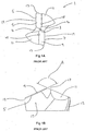
- FIGs 1A and 1B An example of a conventional carbide metal-working twist drill for drilling metal work pieces is shown in Figs 1A and 1B .
- the cutting tip 1 of the twist drill has in a central portion a chisel edge 3 formed between web thinnings 4.
- Cutting edges 5,7 extend from an inner part of the cutting tip where they are joined to respective ends of the chisel edge 3, to the outermost edge of the cutting tip.
- First and second facets 9,11 also known as first and second or primary and secondary clearances
- the chisel edge 3 is formed during grinding of the facets.
- the cutting edges 5,7 and first and second facets (clearances) 9,11 form a 'point' 17 having an angle of about 130°.
- the chisel edge 3 extrudes the metal work piece and cutting edges 5,7 cut into the material of the work piece.
- the twist drill also has a cylindrical land or margin 13 on the outermost side of the twist drill to support the drill in use.
- the 'point' 17 and the cylindrical land 13 are characteristic of metal-working twist drills and these features are not normally found on other types of twist drill.
- Holes 15 extend through the twist drill and allow cutting fluid to be delivered to the cutting edges 5,7 during use. These holes or conduits are characteristic of some metal-working twist drills.
- the twist drill is fluted and rake face 19 causes machined material that has been cut away from the work piece (also known as 'chip') to be directed into the flutes, which in turn move the material away from the cutting tip and out of the bore.
- the cutting edges 5,7 simultaneously engage the work piece that is to be drilled.
- the cutting tip i.e. point 17
- high temperatures and pressures are created at the cutting edge.
- This plasticisation can occur in metal or metal-containing work pieces (e.g. Al, Ti, Ni, steel, stainless steel and alloys and combinations thereof).
- a similar, related problem of fibre pull-out can occur in certain composites such as carbon fibre and glass fibre reinforced plastic work pieces.
- burr, fibre pull-out and de-lamination in work pieces that include two or more layers of different material e.g. metal and composite (e.g. carbon fibre reinforced plastic) layers in the same work piece.
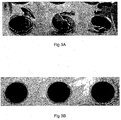
- Plasticised material formed at the cutting edge does not behave in the same way as normal 'chips' and it is not readily deflected into the helical flutes by the rake faces 19. Instead, it can flow to the outer edge of the cutting tip at the sides of the rotating drill, where it cools and forms an exit burr. A similar mechanism can also cause burr caps. Examples of exit burr and burr caps produced by known metal-working twist drills are shown in Fig 3A .
- exit burr and/or burr caps on the work piece is highly undesirable because it requires further machining, or de-burring, to remove the excess material. This can add an entire step to a manufacturing process, with the resultant increase in production complexity and costs. This is a particular problem with hard metal and metal-containing work pieces.
- a further attempt at reducing burr involves providing a cutting edge that has an outer part that is turned inward towards the centre of the cutting tip to form an acute angle relative to the outer periphery of the drill as seen from the axial direction of the drill ( US5078554 ).
- This acute angle feature is said to cause machined material to be directed to the centre of the machined bore.
- This approach does not directly address the problem of plasticisation of machined material, rather it seeks to redirect the plasticised material.
- the 'acute angle' feature is more prone to damage.
- the present invention seeks to address the problem of formation of exit burr and burr caps whilst maintaining drill performance.
- a cutting edge of a metal-working twist drill (e.g. for drilling steel) should have an outer cutting portion that is inclined in the opposite direction to the 'point' formed by inner portions of the cutting edge, so that the plasticisation of the substrate is reduced and the flow of plasticised material is disrupted.
- the present invention provides a twist drill according to claim 1.
- the outer cutting portion can be thought of as having a 'negative' angle in the axial direction because the slope is opposite to that of the rest of the cutting edge (i.e. the point formed by the inner cutting portion), which by convention is normally regarded as having a positive angle.
- the shank includes a rearward attachment end for engagement with means for rotating the twist drill, and it follows that the cutting tip is located at the forward end of the drill.
- a radially outer part of the outer cutting portion is axially spaced in a forward direction with respect to a radially inner part of the outer cutting portion.
- 'point' and 'point angle' are familiar to the person skilled in the art, as is the fact that point angles are regarded as positive, by convention.
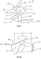
- the point angle of an embodiment of the present invention is shown as feature A in Fig 2B .
- the point angle is the included angle between the primary and secondary cutting edges projected upon a plane parallel to the drill axis and parallel to the two cutting edges.
- body' is familiar to the person skilled in the art.
- the body is the portion of the drill extending from the extreme cutting end to the commencement of the shank.
- the cutting tip includes 2 or more cutting edges (e.g. 2, 3, 4, 5, or 6 cutting edges). Most preferably there are only 2 cutting edges, i.e. primary and secondary cutting edges.
- a shallow V-shaped 'valley' or 'trough' is formed between the inner cutting portion and the outer cutting portion. This valley or trough formed because of the opposite slopes of the inner cutting portion and the outer cutting portion (i.e. as a result of the 'dishing' of the outer cutting portion), may help direct waste material from the bore away from the edges of the tool and into the flutes of the drill. It is also believed that the outer cutting portion breaks up or interferes with the plasticisation and flow of the work piece material as the drill breaks through the work piece surface.
- the cutting edge is continuous, i.e. that the outer cutting portion is part of the cutting edge that extends continuously (unbroken) from an inner to an outer part of the cutting tip.
- the inner cutting portion and the outer cutting portion are joined.
- the radially outermost part of the outer cutting portion is preferably located on the outer peripheral edge of the cutting tip.
- the twist drill includes a cylindrical land (also known as the margin), for providing stability and support when drilling into the work piece, in particular hard work pieces such as steel.
- the outer cutting portion extends to the outermost edge (periphery) of the cylindrical land.
- the twist drill can include double cylindrical lands - one on the leading edge of the flutes and one on the trailing edge of the flutes. This improves stability and support.
- the combined length of the inner and outer cutting portions is at least as long as the diameter of the body of the twist drill.
- Embodiments of the present invention are believed to reduce the pressure on the work piece material as the twist drill breaks through the surface of the work piece. Embodiments may also bring about a lower temperature at the cutting edge, compared to conventional twist drills. Test results indicate that these beneficial effects are caused by the outer cutting portion. In particular, it is thought that the 'negative' angle ('dishing' angle) of the outer cutting portion is responsible for these improvements. It is also believed that the 'valley' or 'trough' not only lowers the pressure at the cutting tip and/or results in a more favourable distribution of pressure, but also assists in breaking up or interfering with the plasticisation and flow of the work piece material as the twist drill breaks through the work piece surface.
- embodiments of the present invention produce bores having a reduced exit burr height as discussed more fully later. Furthermore, even if embodiments of the present invention produce an exit burr cap, it is removed more easily compared to burr caps produced by known metal-working twist drills because the thickness of the material connecting the burr cap to the wall of the bore is much reduced.
- the outer cutting portion is inclined at an angle of from 2° to 8° with respect to a plane normal to the axis of rotation of the tool, preferably 2° to 6°, even more preferably 2° to 5° and most preferably 2° to 4°. This angle is shown as feature B in Fig. 2B .
- the inclined outer cutting portion can, by convention, be regarded as having a negative angle (dishing angles).
- the preferred angles of the burr-reducing edge given above are negative angles.
- the twist drill includes a chisel edge.
- the inner ends of the cutting edges are joined to respective ends of the chisel edge.
- the cutting tip includes web thinnings.
- the point angle is in the range 128° to 160°, more preferably 128° to 150°, more preferably 128° to 145°, and most preferably about 130° to 140°.
- a lower limit for the point angle can be selected from 128° and 130° (i.e. there is a point angle of at least the selected value).
- An upper limit for the point angle can be selected (independently from a lower limit) from 140°, 145°, 150°, 155 and 160° (i.e. there is an angle of no more than the selected value).
- ranges include 128° to 155°, 128° to 150°, 128° to 145° and 128° to 140°.
- Other preferred ranges are 130° to 160°, 130° to 155°, 130° to 150° and 130° to 145°.
- the width of the outer cutting portion is in the range of 5% to 50% of the diameter of the twist drill, more preferably in the range 5% to 40%, even more preferably 5% to 30%, even more preferably 5% to 20% and most preferably 10% to 20%.
- the width of the outer cutting portion is preferably at least a value selected from 5%, 7.5%, 10%, 12.5%, 15% and 17.5% of the diameter of the twist drill.
- the width of the outer cutting portion is no more than a value selected from 12.5%, 15%, 17.5%, 20%, 22.5%, 25%, 27.5% and 30% of the diameter of the twist drill.
- These values can be applied individually or in any combination to define a range. Particularly preferred ranges include 5% to 17.5%, 5% to 15%, 5% to 12.5% and 5% to 10%. Also preferred are 7.5% to 15%, 7.5% to 12.5% and 7.5% to 10%.
- the width of the outer cutting portion is measured from the point at which the inner and outer cutting portions meet (i.e. the "valley" referred to above) to the outer tip of the outer cutting portion. This is indicated as feature D in Fig. 2A .
- the width of the point is preferably in the range 50% to 90% of the diameter of the drill.
- the width is at least a value selected from 50%, 55%, 60%, 65%, 70%, 75%, 80% and 85% of the diameter of the drill.
- the width is no more than a value selected from 75%, 80%, 85%, 90% and 95% of the diameter of the drill.
- the drill diameter is the diameter over the margins of a drill measured at the cutting tip.
- the cutting edge when viewed along the axis of rotation of the twist drill (looking end-on at the cutting tip) is non-linear or curved.
- the cutting edge profile in particular the profile of the inner cutting portion, is curved. It can be curved (or bowed) so that it is convex or concave. Preferably it is convex. Examples of convex cutting edges are given in GB2184046A , which is incorporated herein by reference, in particular the example shown in Figs 3 and 4 and described at page 1, lines 45 to 106 of GB2184046A .
- the outer cutting portion forms an angle, in the radial direction, with the rest of the cutting edge (e.g. the inner cutting portion), when the cutting tip is viewed axially (end-on).
- the outer cutting portion is inclined in the radial direction with respect to the inner cutting portion.
- the outer cutting portion may form an angle of less than 180° with the rest of the cutting edge, e.g. an angle in the range ⁇ 180° to 140°. Preferred angles are in the range ⁇ 180° to >160°. In this way the outer cutting portion may extend in front of the rest of the cutting edge, in the cutting direction of the twist drill.
- the cutting tip includes at least one flank face (also know as a facet or clearance) that extends behind the (preferably each) cutting edge in the opposite direction to the cutting direction, to provide clearance.
- the flank face forms a clearance angle of about 5° to 20°, preferably about 6° to 10°.
- the cutting tip includes two, also preferably three, facets/flank faces associated with the or each cutting edge.
- a second flank face extends behind the first flank face.
- the angle of the second flank face is about 10° to 30°, preferably about 17° to 25°.
- the cutting tip has a first flank face that extends immediately behind the (preferably each) cutting edge to form a clearance angle of about 5° to 20°, preferably about 6° to 10°, and a second flank face that extends behind the first flank face to form a clearance angle of about 10° to 30°, preferably about 17° to 25°.
- the twist drill includes one or more flank faces extending behind the outer cutting portion, in the opposite direction to the cutting direction.
- the clearance angle of such a flank face or faces is/are the same as those described above with respect to the first and second flank faces respectively.
- each of the inner and outer cutting portions have at least one flank face associated therewith.
- the flank face or faces associated with the outer cutting portion are tapered so that they get narrower at greater distances behind the outer cutting portion.
- the taper extends behind the outer cutting portion for a distance equivalent to about 5% to 40% of the circumference of the twist drill, more preferably about 5% to 20%. In certain embodiments this corresponds to flank face or faces length of about 1 mm to 10 mm, preferably about 1 mm to 5 mm.
- flank faces associated with the outer cutting portion can be untapered so that the edges of the flank face remain parallel.
- the width of the flank face associated with the outer cutting portion is the same as the width of the outer cutting portion.
- the widest part of the flank face is preferably the same as the width of the outer cutting portion with which it is associated.
- the twist drill has two or three helical flutes.
- the twist drill has a diameter in the range 1 mm to 50 mm, preferably 1 to 20 mm, more preferably 1 mm to 15 mm, and most preferably 2 mm to 15 mm.
- the present invention provides a twist drill having a rearward attachment end for engagement with means for rotating the twist drill, an axis of rotation about which the twist drill rotates during use, a forward cutting tip, and a cylindrical land to provide body clearance, the cutting tip including primary and secondary cutting edges, respective inner edges of which form a point, the point angle being in the range 128° to 155°, wherein a radially outer part of each of the primary and secondary cutting edges includes an outer cutting portion that is inclined in the opposite axially direction to the respective inner cutting portion, wherein the angle formed by the outer cutting portions with respect to a plane normal to the axis of rotation of the twist drill is in the range >2° to 8°, wherein the cutting edge is continuous and the point and the cutting portion are joined such that a V-shaped valley or trough is formed between the point and the outer cutting portion; the outer cutting portion extends to the outermost edge of the cylindrical land; and the width of the outer cutting portions as measured at the cutting edge is in the range 5% to 30%
- the width of the outer cutting portions is in the range 5% to 15% of the diameter of the twist drill.
- the twist drill includes one or more channels or conduits for delivering coolant or lubricant to the cutting tip.
- these channels or conduits extend from the rearward end of the twist drill to the forward cutting tip.
- the metal-working twist drill is made of carbide.
- a preferred carbide is tungsten carbide.
- Alternative materials of construction include high speed steel (HSS), HSCo and HSCoXP, silicon nitride and PCD (polycrystalline diamond), or combinations thereof (for example PCD mounted on a metal drill).
- the twist drill is coated, partially or fully, with a surface coating such as titanium aluminium nitride (TiAlN).
- a surface coating such as titanium aluminium nitride (TiAlN).
- TiAlN titanium aluminium nitride
- the coating is a wear resistant coating, suitably having a lower coefficient of friction than the uncoated tool.
- Other coatings include TiN, TiCN, AlTiN, DLC (diamond-like carbon), diamond and AlCrN.
- the present invention provides a twist drill having a shank, an axis of rotation about which the twist drill rotates during use, a cutting tip, the cutting tip having a cutting edge, wherein an inner cutting portion of the cutting edge forms a point, the point angle being in the range 128° to 2°, wherein a radially outer part of the cutting edge includes an outer cutting portion that is inclined in the opposite axial direction to the inner cutting portion, at an angle of from 2° to 8° with respect to a plane normal to the axis of rotaion, a cylindrical land wherein the outer cutting portion extends to the outermost edge of the cylindrical land, a primary flank face extending behind the cutting edge in the opposite direction to the cutting direction, and a secondary flank face extending behind the primary flank face in the opposite direction to the cutting direction, wherein the outer cutting portion and the point meet each other.
- the present invention provides a method of manufacturing a twist drill according to claim 13.
- step (i) includes forming 2 or 3 helical flutes.
- step (ii) includes forming a facet at the end of each flute, preferably to produce 2 or 3 cutting edges.
- step (ii) includes applying a conical grind to the cutting tip to produce the cutting edge.
- the step of forming a facet at the end of each flute includes the steps of forming a primary facet behind each cutting edge and, behind each primary facet, a secondary facet.
- the step of forming each facet includes grinding.
- the step of forming the outer cutting portion includes forming a facet at a radially outer portion of the cutting edge.
- the outer cutting portion can be formed using a conical grind.
- the present invention provides a method of modifying a twist drill according to claim 15.
- the step of forming an outer cutting portion includes reforming (preferably regrinding) the cutting edge of the twist drill.
- this involves regrinding the primary and secondary facets.
- the twist drill to be modified has primary and secondary cutting edges and a point angle in the range 128° to 155°.
- the present invention according to claim 16 provides a method of drilling a laminate material wherein a twist drill according to any one of the previous aspects is used to drill the laminate material.
- the present invention includes the use of twist drills according to any one of the previous aspects in a method of drilling a laminate material.
- the twist drill of the present invention is particularly suitable for drilling into laminate (i.e. multilayered) materials because it reduced the problem of delamination.
- Delamination or the pulling apart of layers, of a laminate material is a problem when conventional twist drills are used.
- the problem is significant for the aerospace industry that utilises "stack" material comprising carbon fibre-aluminium laminates (i.e. a layer of carbon fibre material and a layer of aluminium, sometimes known as CFRP/Al - carbon fibre reinforced plastics/AL).
- the carbon fibre layer frays and splinters on the entry side of the drill hole.
- Substantial exit burr is formed on the aluminium exit side.
- the laminate material preferably comprises a fibre-containing layer, e.g. a carbon fibre-containing layer.
- the laminate material includes a metal-containing layer, e.g. an aluminium-containing layer.
- the laminate material comprises a fibre-containing layer and a metal containing layer (preferably a carbon fibre-containing layer and an aluminium-containing layer). It is particularly preferred that the laminate material is a CFRP/A1 material - carbon fibre reinforced plastics/AL.
- drilling starts on the carbon fibre-containing layer (i.e. the entrance hole is on the carbon fibre-containing layer).
- the aluminium-containing layer is the last layer to be drilled (i.e. the exit hole is on the aluminium-containing layer).
- twist drills of the present invention are also particularly suitable for use with laminates comprising more than two layers, e.g. three, four, five or six layers.
- the present invention provides a method of drilling a fibre-containing material wherein a twist drill according to any one of the previous aspects is used to drill the fibre-containing material.
- a twist drill according to any one of the previous aspects is used to drill the fibre-containing material.
- the twist drills of the present invention can reduce the problem of fraying and splintering of fibre-containing materials..
- any one aspect can also apply to any of the other aspects. Furthermore, any one aspect may be combined with one or more of the other aspects.
- Figure 1 shows the cutting end of a conventional twist drill, for example a CDX twist drill as manufactured by Dormer Tools (Sheffield) Ltd. This drill has already been discussed.
- Figs 2A and 2B show an embodiment of the present invention in which the metal-working twist drill is made from carbide.
- carbide Other materials are also possible, for example HSS, etc.
- the cutting tip 51 of the twist drill has many features in common with the conventional twist drill shown in Figs 1A and 1B and the same reference numerals have been used to identify common features.
- This embodiment differs from the conventional twist drill of Fig 1 in that the cutting edges include inner cutting edges 55,57 and, radially outwards of these inner portions, outer cutting portions 59, 61.
- the inner cutting edges form a point 18 that has a 'positive' angle, A, in this case 130°.
- A a 'positive' angle
- Other point angles can also be used, preferably in the range 128° to 155°.
- each cutting edge 55,57 is a outer cutting portion 59,61.
- the outer cutting portions are inclined at an angle, B, of 3° with respect to a plane normal to the axis of rotation. Because the slope of the outer cutting portion has an opposite slope to the point angle, the angle of the outer cutting portion can be regarded as a negative angle, i.e. -3°. Other angles are also possible, preferably in the range >2° to 8°.
- the width of the outer cutting portion, D, as measured at the cutting edge, is 10.5% of the diameter of the twist drill. Other widths are possible, preferably in the range 10% to 30%.
- a third facet 69 extends behind each outer cutting portion, to provide clearance.
- the width of the point, C is 75% of the diameter of the twist drill. Other point widths are possible, preferably in the range 50% to 90%.
- the profile of the inner cutting edge as viewed axially (end-on or plan view of the twist drill) is straight, just like the conventional twist drill of Fig. 1 .
- the inner cutting edge has a bowed (suitably, convex) profile in the radial direction.
- the profile of the outer cutting portion is curved such that the outer peripheral edge of the outer cutting portion lies in front of the rest of the cutting edge, i.e. in the direction of cutting.
- the curved outer cutting portion leads the cutting edge.
- Other profiles are possible, for example, a curved inner cutting edge and straight outer cutting edge.
- the cutting edge of this embodiment has been honed with a diamond grinding tool.
- Other known cutting edge finishing and honing techniques can also be used.
- the twist drill has a diameter of 6.0 mm.
- Other diameters are possible, preferably in the range 1, mm to 50 mm more preferably 1 to 20 mm.
- a drill blank was subjected to the following machining and grinding steps:
- a conventional CDX drill available from Dormer Tools (Sheffield) Ltd, was regrinded to form an outer cutting portion as shown in Figs 2A and 2B .
- the procedure was as set out above for making the twist drill, except that there was no need to form the flutes or body clearance.
- the regrind therefore comprised regrinding the primary and secondary facets, followed by grinding of the third facet, to form the outer cutting portion
- Twist drills of the present invention have proven successful in the reduction of exit burr height.
- Fig 3A shows the exit burr created when a conventional metal-working twist drill (in this case, a CDX drill available from Dormer Tools (Sheffield) Ltd) was used to drill holes in a steel work piece (EN 3B).
- the drill produced a burr cap that was difficult to dislodge.
- a twist drill according to the present invention i.e. very similar to the one shown in Figs 2A and 2B ) produced holes having a much smaller burr height.
- fewer burr caps were produced and those that were still attached to the work piece were easily dislodged because they were connected to the substrate by only a thin piece of burr material.
- Twist drills of the present invention can be used to cut a bore in a variety of metals and composites and in all cases it has been shown to reduce the exit burr height.
- work pieces made of carbon steels, Ti, stainless steel, aluminium, copper, brass and composite materials such as carbon fibre and glass reinforced plastics.
- Embodiments have also led to a reduction in 'de-lamination' whilst drilling composite materials (i.e. work pieces comprising layers of different material).
- FIG. 1 shows the results of a test with a standard drill of the sort shown in Fig 1 .
- the standard drill produced an exit burr height of 0.8 - 1.0 mm.
- the twist drill of the present invention of the sort shown in Fig 2 , consistently produced an exit burr height of between 0.1 - 0.2 mm.
- the twist drill cut for about 25.5 minutes, which equates to 654 holes at the above drilling depth.
- Tests with the twist drill of the present invention show it is capable of achieving drill times in excess of 38 minutes, using the following operational parameters.
- the applicant normally recommends that a drill be capable of a drilling time of 30 minutes, so this requirement is met comfortably by the new twist drill.
- Tests to establish the wear characteristics of twist drills of the present invention indicate that the cutting efficiency and failure rate of the twist drill is comparable to the performance of standard metal-working twist drills of the sort shown in Fig 1 .
- Tests were carried out with a twist drill similar to that shown in Figs 2A and 2B , using the following machine set up and parameters, in AMG 1.2 (similar to EN 3B): • Vertical Machining Centre • 20 bar Through Tool Coolant Speed rpm 3500 Feed mm/min 875 Depth mm 40
- Test results showed a large reduction in exit burr height control, whilst cutting performance was maintained.
- the machine set up was as follows:
- the drill diameters were 8.2 mm and the optimal drilling parameters were found to be as follows: Speed rpm 5240 Feed mm/min (mm/rev) 1048 (0.2) Depth mm 37.40
- the 8.2 mm drills performed well with an average drill life of 38.85 meters of cut.
- the target was to achieve a consistent performance of at least 30 meters, and this was comfortably exceeded.
- the drill produced acceptable swarf, with short chipping, in particular short start and exit chip.
- the productivity was good and comparable to the performance of known metal-working twist drills.
- the main performance criterion was with regards to the minimised burr height and the twist drill geometry of the present invention achieved this with a consistent minimised entry and exit burr height of a maximum of about 0.1mm. In some cases, there was an 'exit cap' produced, but this was easily removed without damage to the work piece.
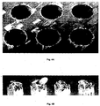
- twist drills of the present invention results in reduced delamination, fraying, hole erosion and splintering, as illustrated in the test below. Furthermore, increased tool life has been achieved, compared to known twist drills.
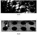
- Figs. 4A and 4B highlight the common problems when drilling CFRP/Al stack material with conventional twist drills: - Fig 4A shows fraying and splintering of the CFRP material; and Fig 4B shows large 'crowning' burrs, which are not an acceptable result when drilling.
- a 118° conical ground point drill was used (there was no inclined outer cutting portion).
- the tool life achieved with the conventional twist drills was between 10-15 holes prior to tool failure.
- Figures 5A and 5B highlight the performance benefits of the new point geometry:- Fig 5A shows minimal splintering and no fraying of the carbon fibre composite; and Fig 5B shows no exit burr produced when exiting the aluminium.
Landscapes
- Engineering & Computer Science (AREA)
- Mechanical Engineering (AREA)
- Drilling Tools (AREA)
Applications Claiming Priority (2)
| Application Number | Priority Date | Filing Date | Title |
|---|---|---|---|
| GB0515898A GB2428611B (en) | 2005-08-02 | 2005-08-02 | Twist drill |
| PCT/GB2006/002890 WO2007015095A1 (en) | 2005-08-02 | 2006-08-02 | Twist drill |
Publications (3)
| Publication Number | Publication Date |
|---|---|
| EP1926567A1 EP1926567A1 (en) | 2008-06-04 |
| EP1926567B1 EP1926567B1 (en) | 2011-06-08 |
| EP1926567B2 true EP1926567B2 (en) | 2017-10-04 |
Family
ID=34983957
Family Applications (1)
| Application Number | Title | Priority Date | Filing Date |
|---|---|---|---|
| EP06765199.2A Active EP1926567B2 (en) | 2005-08-02 | 2006-08-02 | Twist drill |
Country Status (10)
| Country | Link |
|---|---|
| US (1) | US8540463B2 (ja) |
| EP (1) | EP1926567B2 (ja) |
| JP (2) | JP2009502538A (ja) |
| CN (1) | CN101282806B (ja) |
| AT (1) | ATE511934T1 (ja) |
| AU (1) | AU2006274673B2 (ja) |
| BR (1) | BRPI0613966A2 (ja) |
| GB (1) | GB2428611B (ja) |
| RU (1) | RU2414996C2 (ja) |
| WO (1) | WO2007015095A1 (ja) |
Families Citing this family (50)
| Publication number | Priority date | Publication date | Assignee | Title |
|---|---|---|---|---|
| US20090191016A1 (en) * | 2005-04-04 | 2009-07-30 | Osg Corporation | Drill |
| GB2428611B (en) | 2005-08-02 | 2007-10-03 | Dormer Tools | Twist drill |
| FR2919212B1 (fr) * | 2007-07-26 | 2009-12-25 | Snecma | Foret ceramique pour percage grande vitesse de materiaux composites. |
| JP5184878B2 (ja) * | 2007-12-21 | 2013-04-17 | 大見工業株式会社 | ドリル |
| JP2009241239A (ja) * | 2008-03-31 | 2009-10-22 | Fuji Seiko Ltd | ドリルおよび穴あけ加工方法 |
| SE532432C2 (sv) | 2008-05-09 | 2010-01-19 | Sandvik Intellectual Property | Borrkropp med primära och sekundära släppningsytor |
| US8408850B2 (en) * | 2009-06-16 | 2013-04-02 | Kennametal Inc. | Twist drill with negative axial rake transition between the lip and the secondary cutting edge |
| DE102009033942A1 (de) * | 2009-07-14 | 2011-01-20 | MAPAL Fabrik für Präzisionswerkzeuge Dr. Kress KG | Bohrer |
| DE102010012963A1 (de) * | 2010-03-25 | 2011-09-29 | Rolf Klenk Gmbh & Co Kg | Bohrwerkzeug |
| GB201007032D0 (en) * | 2010-04-27 | 2010-06-09 | Dormer Tools Ltd | Twist drill for advanced materials |
| US9539652B2 (en) | 2010-04-30 | 2017-01-10 | Kennametal Inc. | Rotary cutting tool having PCD cutting tip |
| CN101947665A (zh) * | 2010-09-10 | 2011-01-19 | 安徽华星消防设备(集团)有限公司 | 模具打孔冲击钻钻头 |
| DE102010041840A1 (de) * | 2010-10-01 | 2012-04-05 | Bayerische Motoren Werke Aktiengesellschaft | Verfahren zur Herstellung einer Ventilationsbohrung in einem Lagerstuhl eines Kurbelgehäuses einer Hubkolben-Brennkraftmaschine |
| CN107584161A (zh) * | 2010-10-19 | 2018-01-16 | 钴碳化钨硬质合金公司 | 用于旋转切削刀具的pcd切削刃尖和形成该刀具的方法 |
| CN102145401A (zh) * | 2011-04-27 | 2011-08-10 | 江苏飞达钻头股份有限公司 | 高切削性能多刃尖麻花钻 |
| GB2492583A (en) * | 2011-07-06 | 2013-01-09 | Sandvik Intellectual Property | Twist drill for composite materials |
| KR20130032671A (ko) * | 2011-09-23 | 2013-04-02 | 대구텍 유한회사 | 복합 소재용 드릴 공구 |
| CN104338977B (zh) * | 2013-07-30 | 2018-11-27 | 上海名古屋精密工具股份有限公司 | 用于对纤维复合材料进行孔加工的钻头 |
| CN104057125A (zh) * | 2013-11-26 | 2014-09-24 | 李仕清 | 一种机加螺旋凹槽麻花钻的自降温技术及其加工方法 |
| CN103737072A (zh) * | 2013-11-26 | 2014-04-23 | 李仕清 | 一种钣金麻花钻的自降温技术及其加工方法 |
| CN104001972A (zh) * | 2013-11-26 | 2014-08-27 | 李仕清 | 一种机加螺旋复合刃麻花钻的自降温技术及其加工方法 |
| JP6378493B2 (ja) * | 2014-01-31 | 2018-08-22 | 旭ダイヤモンド工業株式会社 | ドリル |
| CN103909299B (zh) * | 2014-03-18 | 2021-05-07 | 大连钢力刃具有限公司 | 金刚石钻头 |
| CN105014124B (zh) * | 2014-04-30 | 2017-07-07 | 深圳市金洲精工科技股份有限公司 | 一种pcb微钻 |
| CN104028812A (zh) * | 2014-06-16 | 2014-09-10 | 同济大学 | 碳纤维复合材料专用钻头 |
| DE102014212714B4 (de) | 2014-07-01 | 2022-02-17 | Kennametal Inc. | Bohrerkopf |
| RU2576356C1 (ru) * | 2014-09-22 | 2016-02-27 | Сергей Николаевич Низов | Спиральное сверло |
| US10005136B2 (en) * | 2014-09-23 | 2018-06-26 | Iscar, Ltd. | Drill or drill head with burnishing margin |
| WO2016047803A1 (ja) * | 2014-09-26 | 2016-03-31 | 三菱マテリアル株式会社 | ドリル及びドリルヘッド |
| JP6589506B2 (ja) * | 2014-09-26 | 2019-10-16 | 三菱マテリアル株式会社 | ドリル及びドリルヘッド |
| CN105033329A (zh) * | 2015-08-27 | 2015-11-11 | 苏州阿诺精密切削技术股份有限公司 | 用于加工难断屑材料的麻花钻 |
| CN105215433B (zh) * | 2015-09-11 | 2017-06-30 | 沈阳航空航天大学 | 一种用于加工纤维增强树脂基复合材料的钻头 |
| SG11201811038WA (en) * | 2016-06-13 | 2019-01-30 | Mitsubishi Gas Chemical Co | Drill bit and hole formation method |
| JP1568742S (ja) * | 2016-09-09 | 2017-02-06 | ||
| CN107952986A (zh) * | 2016-10-17 | 2018-04-24 | 上海精韧激光科技有限公司 | 用于制造切削工具的坯料及其制造方法 |
| EP3528986A4 (en) | 2016-10-21 | 2020-07-22 | Kyocera SGS Precision Tools, Inc. | DRILLS AND THEIR METHODS OF USE |
| CN106513791A (zh) * | 2016-12-30 | 2017-03-22 | 太仓韬信信息科技有限公司 | 加工不锈钢用麻花钻 |
| CN107052408A (zh) * | 2017-01-10 | 2017-08-18 | 深圳市金洲精工科技股份有限公司 | 钻孔工具 |
| CN107327275A (zh) * | 2017-09-11 | 2017-11-07 | 张家港钻通设备有限公司 | 一种具有地层适应广谱性的金刚石钻头 |
| CN107639245A (zh) * | 2017-10-30 | 2018-01-30 | 舟山飞达工具有限公司 | 一种多功能合金刀片 |
| RU183409U1 (ru) * | 2018-04-05 | 2018-09-21 | Федеральное государственное бюджетное образовательное учреждение высшего образования "Кубанский государственный технологический университет" (ФГБОУ ВО "КубГТУ") | Шнековое сверло |
| DE102018205681B4 (de) * | 2018-04-13 | 2023-06-15 | Kennametal Inc. | Verfahren zur Herstellung eines Schneidwerkzeugs und Schneidwerkzeug |
| WO2019244106A1 (en) | 2018-06-22 | 2019-12-26 | Maestro Logistics, Llc | A drill bit and method for making a drill bit |
| JP7375329B2 (ja) * | 2019-04-17 | 2023-11-08 | 三菱マテリアル株式会社 | ドリル |
| DE102019126051A1 (de) * | 2019-09-26 | 2021-04-01 | Kennametal Inc. | Schneidwerkzeug |
| CN110976942A (zh) * | 2019-11-08 | 2020-04-10 | 生益电子股份有限公司 | 用于pcb微孔背钻的背钻刀 |
| RU198358U1 (ru) * | 2020-02-03 | 2020-07-02 | Федеральное государственное бюджетное образовательное учреждение высшего образования "Саратовский государственный технический университет имени Гагарина Ю.А." (СГТУ имени Гагарина Ю.А.) | Сверлильный инструмент |
| CN111421169A (zh) * | 2020-04-17 | 2020-07-17 | 贵州理工学院 | 一种切削铝合金的横刃微槽硬质合金钻头 |
| RU202770U1 (ru) * | 2020-10-13 | 2021-03-05 | Владимир Васильевич Галайко | Фреза концевая |
| CN112507523B (zh) * | 2020-11-16 | 2024-05-17 | 深圳数马电子技术有限公司 | 一种麻花钻模型的建立方法以及装置 |
Citations (4)
| Publication number | Priority date | Publication date | Assignee | Title |
|---|---|---|---|---|
| EP0137898A1 (de) † | 1983-10-04 | 1985-04-24 | Rolf Klenk Hartmetallwerkzeugfabrik GmbH & Co. KG | Vollhartmetallspiralbohrer zur Bearbeitung schwer zerspanbarer Werkstoffe |
| US6113321A (en) † | 1995-07-29 | 2000-09-05 | Black & Decker Inc. | Roll-forged drill bit |
| JP2001252806A (ja) † | 2000-03-08 | 2001-09-18 | Honda Motor Co Ltd | 鋳抜き孔用ドリル |
| EP0893185B1 (en) † | 1997-05-29 | 2003-08-20 | Black & Decker Inc. | Twist drill |
Family Cites Families (44)
| Publication number | Priority date | Publication date | Assignee | Title |
|---|---|---|---|---|
| US2083767A (en) * | 1929-03-13 | 1937-06-15 | Porter W Yett | Apparatus for mixing concrete |
| US2230645A (en) * | 1938-02-01 | 1941-02-04 | Western Electric Co | Drill |
| US2600286A (en) * | 1947-09-08 | 1952-06-10 | Bell Machine Company | Drill bit |
| US2613710A (en) * | 1951-08-02 | 1952-10-14 | Cleveland Twist Drill Co | Machine bit for drilling wood |
| US2652083A (en) * | 1951-08-02 | 1953-09-15 | Cleveland Twist Drill Co | Wood bit |
| US4209275A (en) * | 1978-10-30 | 1980-06-24 | Kim Joo B | Twist drill |
| DE3131794C2 (de) | 1980-08-29 | 1986-08-07 | Toshiaki Osaka Hosoi | Bohrer |
| JPS5771714A (en) | 1980-10-23 | 1982-05-04 | Toshiba Corp | Drill for hard to cutting material |
| US4529341A (en) | 1982-09-29 | 1985-07-16 | Hughes Helicopters, Inc. | Drill bit for Kevlar laminates |
| JPS59148206A (ja) | 1983-02-14 | 1984-08-24 | 三菱電機株式会社 | 放電灯装置 |
| JPS59148206U (ja) * | 1983-03-22 | 1984-10-03 | 住友電気工業株式会社 | ドリル |
| DE3344620A1 (de) * | 1983-12-09 | 1985-06-20 | Hartmetallwerkzeugfabrik Andreas Maier GmbH + Co KG, 7959 Schwendi | Mehrschneidenbohrer |
| SU1238905A1 (ru) | 1984-09-12 | 1986-06-23 | Харьковский Ордена Ленина Политехнический Институт Им.В.И.Ленина | Сверло дл сверлени полимерных композиционных материалов |
| GB2184046B (en) | 1985-12-13 | 1990-01-24 | Skf & Dormer Tools | Twist drill |
| US5288183A (en) * | 1986-08-18 | 1994-02-22 | Black & Decker Inc. | Self-centering drill bit with pilot tip |
| US4968193A (en) * | 1986-08-18 | 1990-11-06 | Black & Decker Corporation | Self-centering drill bit with pilot tip |
| JPH02198707A (ja) | 1989-01-24 | 1990-08-07 | Masao Kubota | ドリル |
| JP2699527B2 (ja) | 1989-03-09 | 1998-01-19 | 三菱マテリアル株式会社 | ツイストドリル |
| JPH02237711A (ja) * | 1989-03-09 | 1990-09-20 | Mitsubishi Heavy Ind Ltd | ツイストドリル |
| JPH02237712A (ja) * | 1989-03-09 | 1990-09-20 | Mitsubishi Heavy Ind Ltd | ツイストドリル |
| US5056967A (en) | 1989-03-28 | 1991-10-15 | Premier Industrial Corporation | Spotweld removal tool |
| JPH03117507A (ja) * | 1989-09-29 | 1991-05-20 | Kobe Steel Ltd | ドリル |
| US5273380A (en) | 1992-07-31 | 1993-12-28 | Musacchia James E | Drill bit point |
| US5731046A (en) | 1994-01-18 | 1998-03-24 | Qqc, Inc. | Fabrication of diamond and diamond-like carbon coatings |
| JP3307809B2 (ja) * | 1995-10-05 | 2002-07-24 | 兼房株式会社 | シャンク付回転工具 |
| DE59804976D1 (de) | 1997-09-09 | 2002-09-05 | Sphinx Werkzeuge Ag Biberist | Mehrschneidiger Bohrer |
| DE29722002U1 (de) | 1997-12-15 | 1998-02-05 | Werkzeugfabrik Gmbh Koenigsee | Spiralbohrer |
| JP2000005914A (ja) | 1998-04-20 | 2000-01-11 | Kanex Hamono Kogyo Kk | ドリル及びその製造方法 |
| SE516229C2 (sv) * | 2000-05-26 | 2001-12-03 | Eero Nygaard | Borrspets |
| JP2002144125A (ja) | 2000-08-31 | 2002-05-21 | Mitsubishi Materials Corp | 穴明け工具 |
| US6585460B1 (en) | 2000-11-13 | 2003-07-01 | General Electric Company | Drill having machine grindable cutting edge |
| DE10106035B4 (de) * | 2001-02-09 | 2008-12-11 | Scintilla Ag | Metallbohrer |
| JP2002326109A (ja) | 2001-04-26 | 2002-11-12 | Allied Material Corp | ドリル |
| JP2003220507A (ja) | 2002-01-24 | 2003-08-05 | Nachi Fujikoshi Corp | ツイストドリル |
| DE20211592U1 (de) | 2002-07-15 | 2004-04-01 | Gühring, Jörg, Dr. | Bohrer |
| DE10308089A1 (de) * | 2003-02-24 | 2004-09-02 | Airbus Deutschland Gmbh | Bohrvorrichtung |
| JP2004268165A (ja) * | 2003-03-05 | 2004-09-30 | Honda Motor Co Ltd | 深穴加工用ドリル |
| EP1512476B1 (en) * | 2003-09-08 | 2013-10-09 | Black & Decker Inc. | Self-centering drill bit with pilot tip |
| US20050053439A1 (en) * | 2003-09-09 | 2005-03-10 | Yuhong Wang | Two-flute twist drill |
| FR2861001B1 (fr) * | 2003-10-16 | 2007-06-22 | Snecma Moteurs | Foret ceramique pour percage grande vitesse |
| CN2663065Y (zh) * | 2003-12-24 | 2004-12-15 | 江苏天工工具股份有限公司 | 多用途麻花钻 |
| GB2428611B (en) | 2005-08-02 | 2007-10-03 | Dormer Tools | Twist drill |
| FR2919212B1 (fr) * | 2007-07-26 | 2009-12-25 | Snecma | Foret ceramique pour percage grande vitesse de materiaux composites. |
| SE532432C2 (sv) * | 2008-05-09 | 2010-01-19 | Sandvik Intellectual Property | Borrkropp med primära och sekundära släppningsytor |
-
2005
- 2005-08-02 GB GB0515898A patent/GB2428611B/en active Active
-
2006
- 2006-08-02 EP EP06765199.2A patent/EP1926567B2/en active Active
- 2006-08-02 AU AU2006274673A patent/AU2006274673B2/en not_active Ceased
- 2006-08-02 US US11/996,716 patent/US8540463B2/en active Active
- 2006-08-02 CN CN2006800285245A patent/CN101282806B/zh active Active
- 2006-08-02 WO PCT/GB2006/002890 patent/WO2007015095A1/en active Application Filing
- 2006-08-02 RU RU2008107969/02A patent/RU2414996C2/ru not_active IP Right Cessation
- 2006-08-02 AT AT06765199T patent/ATE511934T1/de not_active IP Right Cessation
- 2006-08-02 JP JP2008524586A patent/JP2009502538A/ja active Pending
- 2006-08-02 BR BRPI0613966-3A patent/BRPI0613966A2/pt not_active IP Right Cessation
-
2013
- 2013-03-06 JP JP2013044218A patent/JP5600765B2/ja active Active
Patent Citations (4)
| Publication number | Priority date | Publication date | Assignee | Title |
|---|---|---|---|---|
| EP0137898A1 (de) † | 1983-10-04 | 1985-04-24 | Rolf Klenk Hartmetallwerkzeugfabrik GmbH & Co. KG | Vollhartmetallspiralbohrer zur Bearbeitung schwer zerspanbarer Werkstoffe |
| US6113321A (en) † | 1995-07-29 | 2000-09-05 | Black & Decker Inc. | Roll-forged drill bit |
| EP0893185B1 (en) † | 1997-05-29 | 2003-08-20 | Black & Decker Inc. | Twist drill |
| JP2001252806A (ja) † | 2000-03-08 | 2001-09-18 | Honda Motor Co Ltd | 鋳抜き孔用ドリル |
Also Published As
| Publication number | Publication date |
|---|---|
| EP1926567A1 (en) | 2008-06-04 |
| AU2006274673B2 (en) | 2012-02-23 |
| RU2008107969A (ru) | 2009-09-10 |
| US20090087275A1 (en) | 2009-04-02 |
| GB2428611A (en) | 2007-02-07 |
| EP1926567B1 (en) | 2011-06-08 |
| JP2009502538A (ja) | 2009-01-29 |
| WO2007015095A1 (en) | 2007-02-08 |
| ATE511934T1 (de) | 2011-06-15 |
| GB2428611B (en) | 2007-10-03 |
| CN101282806A (zh) | 2008-10-08 |
| CN101282806B (zh) | 2010-12-22 |
| RU2414996C2 (ru) | 2011-03-27 |
| AU2006274673A1 (en) | 2007-02-08 |
| BRPI0613966A2 (pt) | 2011-02-22 |
| JP5600765B2 (ja) | 2014-10-01 |
| GB0515898D0 (en) | 2005-09-07 |
| JP2013099851A (ja) | 2013-05-23 |
| US8540463B2 (en) | 2013-09-24 |
Similar Documents
| Publication | Publication Date | Title |
|---|---|---|
| EP1926567B2 (en) | Twist drill | |
| US5967712A (en) | Cutting tool for machining bores in materials having spring-back | |
| US7832966B2 (en) | Drill for making flat bottom hole | |
| US6929434B2 (en) | Rotary cutting tool | |
| RU2409454C2 (ru) | Концевая фреза для орбитального фрезерования | |
| US10391592B2 (en) | Manufacturing of holemaking tools | |
| CN106132607B (zh) | 带聚晶金刚石烧结体的旋转切削工具 | |
| US7140815B2 (en) | Drill for making flat bottom hole | |
| JP2003300110A (ja) | ドリルおよびその製造方法 | |
| US9669474B2 (en) | Single-lip drill | |
| JP2004160651A (ja) | ガンドリル | |
| WO2010086988A1 (ja) | ダブルアングルドリル | |
| US20070041801A1 (en) | Single-lip drill and method for the production thereof | |
| CN110560753A (zh) | 一种钻滚组合成型刀 | |
| JP4876650B2 (ja) | 穴加工工具 | |
| EP4194127A1 (en) | Method for producing a drill tool cutting section and such a drill tool cutting section | |
| JP2005059120A (ja) | 切削工具 | |
| Chandler | Machining of refractory metals |
Legal Events
| Date | Code | Title | Description |
|---|---|---|---|
| PUAI | Public reference made under article 153(3) epc to a published international application that has entered the european phase |
Free format text: ORIGINAL CODE: 0009012 |
|
| 17P | Request for examination filed |
Effective date: 20080220 |
|
| AK | Designated contracting states |
Kind code of ref document: A1 Designated state(s): AT BE BG CH CY CZ DE DK EE ES FI FR GB GR HU IE IS IT LI LT LU LV MC NL PL PT RO SE SI SK TR |
|
| 17Q | First examination report despatched |
Effective date: 20080602 |
|
| RAP1 | Party data changed (applicant data changed or rights of an application transferred) |
Owner name: DORMER TOOLS LIMITED |
|
| GRAP | Despatch of communication of intention to grant a patent |
Free format text: ORIGINAL CODE: EPIDOSNIGR1 |
|
| GRAS | Grant fee paid |
Free format text: ORIGINAL CODE: EPIDOSNIGR3 |
|
| GRAA | (expected) grant |
Free format text: ORIGINAL CODE: 0009210 |
|
| AK | Designated contracting states |
Kind code of ref document: B1 Designated state(s): AT BE BG CH CY CZ DE DK EE ES FI FR GB GR HU IE IS IT LI LT LU LV MC NL PL PT RO SE SI SK TR |
|
| REG | Reference to a national code |
Ref country code: GB Ref legal event code: FG4D |
|
| REG | Reference to a national code |
Ref country code: CH Ref legal event code: EP |
|
| REG | Reference to a national code |
Ref country code: IE Ref legal event code: FG4D |
|
| REG | Reference to a national code |
Ref country code: DE Ref legal event code: R096 Ref document number: 602006022420 Country of ref document: DE Effective date: 20110721 |
|
| REG | Reference to a national code |
Ref country code: SE Ref legal event code: TRGR |
|
| REG | Reference to a national code |
Ref country code: NL Ref legal event code: VDEP Effective date: 20110608 |
|
| PG25 | Lapsed in a contracting state [announced via postgrant information from national office to epo] |
Ref country code: LT Free format text: LAPSE BECAUSE OF FAILURE TO SUBMIT A TRANSLATION OF THE DESCRIPTION OR TO PAY THE FEE WITHIN THE PRESCRIBED TIME-LIMIT Effective date: 20110608 |
|
| PG25 | Lapsed in a contracting state [announced via postgrant information from national office to epo] |
Ref country code: GR Free format text: LAPSE BECAUSE OF FAILURE TO SUBMIT A TRANSLATION OF THE DESCRIPTION OR TO PAY THE FEE WITHIN THE PRESCRIBED TIME-LIMIT Effective date: 20110909 Ref country code: LV Free format text: LAPSE BECAUSE OF FAILURE TO SUBMIT A TRANSLATION OF THE DESCRIPTION OR TO PAY THE FEE WITHIN THE PRESCRIBED TIME-LIMIT Effective date: 20110608 Ref country code: FI Free format text: LAPSE BECAUSE OF FAILURE TO SUBMIT A TRANSLATION OF THE DESCRIPTION OR TO PAY THE FEE WITHIN THE PRESCRIBED TIME-LIMIT Effective date: 20110608 Ref country code: AT Free format text: LAPSE BECAUSE OF FAILURE TO SUBMIT A TRANSLATION OF THE DESCRIPTION OR TO PAY THE FEE WITHIN THE PRESCRIBED TIME-LIMIT Effective date: 20110608 Ref country code: ES Free format text: LAPSE BECAUSE OF FAILURE TO SUBMIT A TRANSLATION OF THE DESCRIPTION OR TO PAY THE FEE WITHIN THE PRESCRIBED TIME-LIMIT Effective date: 20110919 Ref country code: SI Free format text: LAPSE BECAUSE OF FAILURE TO SUBMIT A TRANSLATION OF THE DESCRIPTION OR TO PAY THE FEE WITHIN THE PRESCRIBED TIME-LIMIT Effective date: 20110608 Ref country code: CY Free format text: LAPSE BECAUSE OF FAILURE TO SUBMIT A TRANSLATION OF THE DESCRIPTION OR TO PAY THE FEE WITHIN THE PRESCRIBED TIME-LIMIT Effective date: 20110608 |
|
| PG25 | Lapsed in a contracting state [announced via postgrant information from national office to epo] |
Ref country code: BE Free format text: LAPSE BECAUSE OF FAILURE TO SUBMIT A TRANSLATION OF THE DESCRIPTION OR TO PAY THE FEE WITHIN THE PRESCRIBED TIME-LIMIT Effective date: 20110608 Ref country code: NL Free format text: LAPSE BECAUSE OF FAILURE TO SUBMIT A TRANSLATION OF THE DESCRIPTION OR TO PAY THE FEE WITHIN THE PRESCRIBED TIME-LIMIT Effective date: 20110608 |
|
| PG25 | Lapsed in a contracting state [announced via postgrant information from national office to epo] |
Ref country code: PT Free format text: LAPSE BECAUSE OF FAILURE TO SUBMIT A TRANSLATION OF THE DESCRIPTION OR TO PAY THE FEE WITHIN THE PRESCRIBED TIME-LIMIT Effective date: 20111010 Ref country code: CZ Free format text: LAPSE BECAUSE OF FAILURE TO SUBMIT A TRANSLATION OF THE DESCRIPTION OR TO PAY THE FEE WITHIN THE PRESCRIBED TIME-LIMIT Effective date: 20110608 Ref country code: EE Free format text: LAPSE BECAUSE OF FAILURE TO SUBMIT A TRANSLATION OF THE DESCRIPTION OR TO PAY THE FEE WITHIN THE PRESCRIBED TIME-LIMIT Effective date: 20110608 Ref country code: IS Free format text: LAPSE BECAUSE OF FAILURE TO SUBMIT A TRANSLATION OF THE DESCRIPTION OR TO PAY THE FEE WITHIN THE PRESCRIBED TIME-LIMIT Effective date: 20111008 |
|
| PG25 | Lapsed in a contracting state [announced via postgrant information from national office to epo] |
Ref country code: SK Free format text: LAPSE BECAUSE OF FAILURE TO SUBMIT A TRANSLATION OF THE DESCRIPTION OR TO PAY THE FEE WITHIN THE PRESCRIBED TIME-LIMIT Effective date: 20110608 Ref country code: RO Free format text: LAPSE BECAUSE OF FAILURE TO SUBMIT A TRANSLATION OF THE DESCRIPTION OR TO PAY THE FEE WITHIN THE PRESCRIBED TIME-LIMIT Effective date: 20110608 Ref country code: PL Free format text: LAPSE BECAUSE OF FAILURE TO SUBMIT A TRANSLATION OF THE DESCRIPTION OR TO PAY THE FEE WITHIN THE PRESCRIBED TIME-LIMIT Effective date: 20110608 |
|
| PLBI | Opposition filed |
Free format text: ORIGINAL CODE: 0009260 |
|
| PG25 | Lapsed in a contracting state [announced via postgrant information from national office to epo] |
Ref country code: MC Free format text: LAPSE BECAUSE OF NON-PAYMENT OF DUE FEES Effective date: 20110831 |
|
| REG | Reference to a national code |
Ref country code: CH Ref legal event code: PL |
|
| PLAX | Notice of opposition and request to file observation + time limit sent |
Free format text: ORIGINAL CODE: EPIDOSNOBS2 |
|
| 26 | Opposition filed |
Opponent name: ISCAR LTD. Effective date: 20120308 |
|
| PG25 | Lapsed in a contracting state [announced via postgrant information from national office to epo] |
Ref country code: CH Free format text: LAPSE BECAUSE OF NON-PAYMENT OF DUE FEES Effective date: 20110831 Ref country code: LI Free format text: LAPSE BECAUSE OF NON-PAYMENT OF DUE FEES Effective date: 20110831 |
|
| REG | Reference to a national code |
Ref country code: IE Ref legal event code: MM4A |
|
| PG25 | Lapsed in a contracting state [announced via postgrant information from national office to epo] |
Ref country code: IT Free format text: LAPSE BECAUSE OF FAILURE TO SUBMIT A TRANSLATION OF THE DESCRIPTION OR TO PAY THE FEE WITHIN THE PRESCRIBED TIME-LIMIT Effective date: 20110608 |
|
| REG | Reference to a national code |
Ref country code: DE Ref legal event code: R026 Ref document number: 602006022420 Country of ref document: DE Effective date: 20120308 |
|
| PG25 | Lapsed in a contracting state [announced via postgrant information from national office to epo] |
Ref country code: DK Free format text: LAPSE BECAUSE OF FAILURE TO SUBMIT A TRANSLATION OF THE DESCRIPTION OR TO PAY THE FEE WITHIN THE PRESCRIBED TIME-LIMIT Effective date: 20110608 |
|
| PG25 | Lapsed in a contracting state [announced via postgrant information from national office to epo] |
Ref country code: IE Free format text: LAPSE BECAUSE OF NON-PAYMENT OF DUE FEES Effective date: 20110802 |
|
| PLAF | Information modified related to communication of a notice of opposition and request to file observations + time limit |
Free format text: ORIGINAL CODE: EPIDOSCOBS2 |
|
| PLBB | Reply of patent proprietor to notice(s) of opposition received |
Free format text: ORIGINAL CODE: EPIDOSNOBS3 |
|
| PG25 | Lapsed in a contracting state [announced via postgrant information from national office to epo] |
Ref country code: LU Free format text: LAPSE BECAUSE OF NON-PAYMENT OF DUE FEES Effective date: 20110802 |
|
| PG25 | Lapsed in a contracting state [announced via postgrant information from national office to epo] |
Ref country code: BG Free format text: LAPSE BECAUSE OF FAILURE TO SUBMIT A TRANSLATION OF THE DESCRIPTION OR TO PAY THE FEE WITHIN THE PRESCRIBED TIME-LIMIT Effective date: 20110908 |
|
| PLAB | Opposition data, opponent's data or that of the opponent's representative modified |
Free format text: ORIGINAL CODE: 0009299OPPO |
|
| PG25 | Lapsed in a contracting state [announced via postgrant information from national office to epo] |
Ref country code: TR Free format text: LAPSE BECAUSE OF FAILURE TO SUBMIT A TRANSLATION OF THE DESCRIPTION OR TO PAY THE FEE WITHIN THE PRESCRIBED TIME-LIMIT Effective date: 20110608 |
|
| R26 | Opposition filed (corrected) |
Opponent name: ISCAR LTD. Effective date: 20120308 |
|
| PG25 | Lapsed in a contracting state [announced via postgrant information from national office to epo] |
Ref country code: HU Free format text: LAPSE BECAUSE OF FAILURE TO SUBMIT A TRANSLATION OF THE DESCRIPTION OR TO PAY THE FEE WITHIN THE PRESCRIBED TIME-LIMIT Effective date: 20110608 |
|
| PLCK | Communication despatched that opposition was rejected |
Free format text: ORIGINAL CODE: EPIDOSNREJ1 |
|
| APAH | Appeal reference modified |
Free format text: ORIGINAL CODE: EPIDOSCREFNO |
|
| APBM | Appeal reference recorded |
Free format text: ORIGINAL CODE: EPIDOSNREFNO |
|
| APBP | Date of receipt of notice of appeal recorded |
Free format text: ORIGINAL CODE: EPIDOSNNOA2O |
|
| APBQ | Date of receipt of statement of grounds of appeal recorded |
Free format text: ORIGINAL CODE: EPIDOSNNOA3O |
|
| APAH | Appeal reference modified |
Free format text: ORIGINAL CODE: EPIDOSCREFNO |
|
| APAH | Appeal reference modified |
Free format text: ORIGINAL CODE: EPIDOSCREFNO |
|
| REG | Reference to a national code |
Ref country code: FR Ref legal event code: PLFP Year of fee payment: 11 |
|
| APBU | Appeal procedure closed |
Free format text: ORIGINAL CODE: EPIDOSNNOA9O |
|
| RIN2 | Information on inventor provided after grant (corrected) |
Inventor name: GOULBOURNE, DAVID |
|
| REG | Reference to a national code |
Ref country code: FR Ref legal event code: PLFP Year of fee payment: 12 |
|
| PUAH | Patent maintained in amended form |
Free format text: ORIGINAL CODE: 0009272 |
|
| STAA | Information on the status of an ep patent application or granted ep patent |
Free format text: STATUS: PATENT MAINTAINED AS AMENDED |
|
| 27A | Patent maintained in amended form |
Effective date: 20171004 |
|
| AK | Designated contracting states |
Kind code of ref document: B2 Designated state(s): AT BE BG CH CY CZ DE DK EE ES FI FR GB GR HU IE IS IT LI LT LU LV MC NL PL PT RO SE SI SK TR |
|
| REG | Reference to a national code |
Ref country code: DE Ref legal event code: R102 Ref document number: 602006022420 Country of ref document: DE |
|
| PGFP | Annual fee paid to national office [announced via postgrant information from national office to epo] |
Ref country code: SE Payment date: 20170810 Year of fee payment: 12 |
|
| REG | Reference to a national code |
Ref country code: SE Ref legal event code: NAV |
|
| PG25 | Lapsed in a contracting state [announced via postgrant information from national office to epo] |
Ref country code: LV Free format text: LAPSE BECAUSE OF FAILURE TO SUBMIT A TRANSLATION OF THE DESCRIPTION OR TO PAY THE FEE WITHIN THE PRESCRIBED TIME-LIMIT Effective date: 20171004 |
|
| PG25 | Lapsed in a contracting state [announced via postgrant information from national office to epo] |
Ref country code: FR Free format text: LAPSE BECAUSE OF NON-PAYMENT OF DUE FEES Effective date: 20180831 |
|
| PG25 | Lapsed in a contracting state [announced via postgrant information from national office to epo] |
Ref country code: SE Free format text: LAPSE BECAUSE OF NON-PAYMENT OF DUE FEES Effective date: 20180802 |
|
| PGFP | Annual fee paid to national office [announced via postgrant information from national office to epo] |
Ref country code: GB Payment date: 20230706 Year of fee payment: 18 |
|
| PGFP | Annual fee paid to national office [announced via postgrant information from national office to epo] |
Ref country code: DE Payment date: 20230705 Year of fee payment: 18 |