EP1925985B1 - Bilderzeugungsvorrichtung und Leistungsübertragungseinheit dafür - Google Patents
Bilderzeugungsvorrichtung und Leistungsübertragungseinheit dafür Download PDFInfo
- Publication number
- EP1925985B1 EP1925985B1 EP07120496.0A EP07120496A EP1925985B1 EP 1925985 B1 EP1925985 B1 EP 1925985B1 EP 07120496 A EP07120496 A EP 07120496A EP 1925985 B1 EP1925985 B1 EP 1925985B1
- Authority
- EP
- European Patent Office
- Prior art keywords
- driven
- assembling
- connecting part
- selectively connecting
- image forming
- Prior art date
- Legal status (The legal status is an assumption and is not a legal conclusion. Google has not performed a legal analysis and makes no representation as to the accuracy of the status listed.)
- Ceased
Links
Images


Classifications
-
- G—PHYSICS
- G03—PHOTOGRAPHY; CINEMATOGRAPHY; ANALOGOUS TECHNIQUES USING WAVES OTHER THAN OPTICAL WAVES; ELECTROGRAPHY; HOLOGRAPHY
- G03G—ELECTROGRAPHY; ELECTROPHOTOGRAPHY; MAGNETOGRAPHY
- G03G15/00—Apparatus for electrographic processes using a charge pattern
-
- G—PHYSICS
- G03—PHOTOGRAPHY; CINEMATOGRAPHY; ANALOGOUS TECHNIQUES USING WAVES OTHER THAN OPTICAL WAVES; ELECTROGRAPHY; HOLOGRAPHY
- G03G—ELECTROGRAPHY; ELECTROPHOTOGRAPHY; MAGNETOGRAPHY
- G03G15/00—Apparatus for electrographic processes using a charge pattern
- G03G15/06—Apparatus for electrographic processes using a charge pattern for developing
- G03G15/08—Apparatus for electrographic processes using a charge pattern for developing using a solid developer, e.g. powder developer
- G03G15/0896—Arrangements or disposition of the complete developer unit or parts thereof not provided for by groups G03G15/08 - G03G15/0894
-
- G—PHYSICS
- G03—PHOTOGRAPHY; CINEMATOGRAPHY; ANALOGOUS TECHNIQUES USING WAVES OTHER THAN OPTICAL WAVES; ELECTROGRAPHY; HOLOGRAPHY
- G03G—ELECTROGRAPHY; ELECTROPHOTOGRAPHY; MAGNETOGRAPHY
- G03G15/00—Apparatus for electrographic processes using a charge pattern
- G03G15/01—Apparatus for electrographic processes using a charge pattern for producing multicoloured copies
- G03G15/0142—Structure of complete machines
- G03G15/0147—Structure of complete machines using a single reusable electrographic recording member
- G03G15/0152—Structure of complete machines using a single reusable electrographic recording member onto which the monocolour toner images are superposed before common transfer from the recording member
- G03G15/0173—Structure of complete machines using a single reusable electrographic recording member onto which the monocolour toner images are superposed before common transfer from the recording member plural rotations of recording member to produce multicoloured copy, e.g. rotating set of developing units
-
- G—PHYSICS
- G03—PHOTOGRAPHY; CINEMATOGRAPHY; ANALOGOUS TECHNIQUES USING WAVES OTHER THAN OPTICAL WAVES; ELECTROGRAPHY; HOLOGRAPHY
- G03G—ELECTROGRAPHY; ELECTROPHOTOGRAPHY; MAGNETOGRAPHY
- G03G15/00—Apparatus for electrographic processes using a charge pattern
- G03G15/06—Apparatus for electrographic processes using a charge pattern for developing
-
- G—PHYSICS
- G03—PHOTOGRAPHY; CINEMATOGRAPHY; ANALOGOUS TECHNIQUES USING WAVES OTHER THAN OPTICAL WAVES; ELECTROGRAPHY; HOLOGRAPHY
- G03G—ELECTROGRAPHY; ELECTROPHOTOGRAPHY; MAGNETOGRAPHY
- G03G2221/00—Processes not provided for by group G03G2215/00, e.g. cleaning or residual charge elimination
- G03G2221/16—Mechanical means for facilitating the maintenance of the apparatus, e.g. modular arrangements and complete machine concepts
- G03G2221/1603—Mechanical means for facilitating the maintenance of the apparatus, e.g. modular arrangements and complete machine concepts for multicoloured copies
-
- G—PHYSICS
- G03—PHOTOGRAPHY; CINEMATOGRAPHY; ANALOGOUS TECHNIQUES USING WAVES OTHER THAN OPTICAL WAVES; ELECTROGRAPHY; HOLOGRAPHY
- G03G—ELECTROGRAPHY; ELECTROPHOTOGRAPHY; MAGNETOGRAPHY
- G03G2221/00—Processes not provided for by group G03G2215/00, e.g. cleaning or residual charge elimination
- G03G2221/16—Mechanical means for facilitating the maintenance of the apparatus, e.g. modular arrangements and complete machine concepts
- G03G2221/1651—Mechanical means for facilitating the maintenance of the apparatus, e.g. modular arrangements and complete machine concepts for connecting the different parts
- G03G2221/1657—Mechanical means for facilitating the maintenance of the apparatus, e.g. modular arrangements and complete machine concepts for connecting the different parts transmitting mechanical drive power
-
- G—PHYSICS
- G03—PHOTOGRAPHY; CINEMATOGRAPHY; ANALOGOUS TECHNIQUES USING WAVES OTHER THAN OPTICAL WAVES; ELECTROGRAPHY; HOLOGRAPHY
- G03G—ELECTROGRAPHY; ELECTROPHOTOGRAPHY; MAGNETOGRAPHY
- G03G2221/00—Processes not provided for by group G03G2215/00, e.g. cleaning or residual charge elimination
- G03G2221/16—Mechanical means for facilitating the maintenance of the apparatus, e.g. modular arrangements and complete machine concepts
- G03G2221/1678—Frame structures
- G03G2221/169—Structural door designs
Definitions
- the present invention relates to an image forming apparatus and a power transmission unit thereof, and more particularly, to an image forming apparatus having a power transmission unit that can stably transmit power to a rotating body.
- an electrophotographic image forming apparatus scans light onto a photosensitive drum electrified to a predetermined transmitting potential to form an electro-static latent image thereon. Then, the electrophotographic image forming apparatus develops the electro-static latent image into a predetermined color toner by a developing cartridge, and transfers and fuses the toner onto a print medium to thereby print a single-color image or a multi-color image on the print medium.
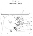
- a conventional electrophotographic image forming apparatus 1 includes a photosensitive drum 10 and a plurality of developing cartridges 20 that are provided along an external circumference surface of the photosensitive drum 10.
- the developing cartridges 20 store black (K), yellow (Y), magenta (M), and cyan (C) toners, and each include a developing roller 23 that is exposed to the photosensitive drum 10 side. Also, the developing cartridges 20 are detachable from a main body (not shown) of the image forming apparatus 1.
- a driven gear 23a is provided on one end part of a rotational axis of each of the developing rollers 23.
- a drum driving coupling 4 to drive the photosensitive drum 10
- developing device driving gears 7C, 7M, 7Y, and 7K that engage the driven gears 23a of the developing rollers 23 if the developing cartridges 20 are mounted.
- a type in which a color image is formed by using one photosensitive drum 10, as shown in FIG. 1A is called a multi-pass type. In the multi-pass type, each of the developing cartridges 20 must be sequentially driven to form the color image.
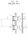
- FIG. 1B only two of the four developing device driving gears 7Y and 7K of FIG. 1A have been illustrated for a convenience of description as they have the same operating configurations.
- the developing device driving gears 7Y and 7K engage connecting gears 6Y and 6K if power is transmitted, and disengage the connecting gears 6Y and 6K if power is blocked.
- the connecting gears 6Y and 6K are engaged and disengaged with/from the developing device driving gears 7Y and 7K by cams 5Y and 5K that rotate with respect to a rotating axis 5a at a proper time.
- the degree of teeth-engagement between the developing device driving gears 7C, 7M, 7Y, and 7K and the driven gears 23a may be different by a manufacturing tolerance and an assembling position tolerance of parts if each of the developing cartridges 20 is mounted. Accordingly, a strict common difference control has to be performed to stably drive the developing cartridges 20 in a single part and assembling parts, thereby raising a manufacturing cost.
- an interval G between the developing roller 23 and the photosensitive drum 10 differs according to the developing cartridges 20. Accordingly, the density of the toner differs according to each color. As a result, the color image formed by toners having different densities may be an inferior image (such as a distorted color).
- JP2000/206754 discloses a coupling mechanism for a photo receptor assembly.
- EP1 653 296 discloses a drive means for an image forming device.
- EP1 211576 discloses a drive mechanism for a process cartridge of an image forming device.
- EP1 178 370 discloses a drive mechanism for an image forming device.
- the invention provides an image forming apparatus and a power transmission unit thereof that can stably transmit power to a developing cartridge to save a manufacturing cost, and decrease an inferior image quality.
- an image forming apparatus including: a driven rotational body that is detachable from the image forming apparatus and includes a driven connecting part; a transmission member that receives a rotational power and includes a driving connecting part provided along a direction of a rotational axial line of the driven rotational body; and an assembling member that receives the rotational power from the transmission member, transmits the rotational power to the driven rotational body to rotate the driven rotational body, and includes a driven side assembling part to connect to the driven connecting part, and a driving side assembling part to connect to the driving connecting part.
- the transmission member may include a power receiving part to receive the rotational power, and a driving part to drive the power receiving part.
- the image forming apparatus may further include a first selectively connecting part to selectively move the transmission member along the direction of the rotational axial line so that the driving connecting part engages or disengages from the driving side assembling part of the assembling member.
- the first selectively connecting part may include a cam and/or a solenoid.
- the image forming apparatus may further include a controller to control the first selectively connecting part to engage the driving connecting part with the driving side assembling part if the driven rotational body requires the rotational power.
- the image forming apparatus may further include a second selectively connecting part to selectively move the assembling member along the direction of the rotational axial line so that the driven side assembling part engages or disengages from the driven connecting part of the rotational body.
- the second selectively connecting part may include: a first selectively connecting member to rotate around the rotational axial line; and a second selectively connecting member connected to the assembling member such that the second selectively connecting member moves together with the assembling member toward or away from the driven connecting part according to a direction that the first selectively connecting member rotates.
- the first selectively connecting member may include a cam provided along a circumference around the rotational axial line
- the second selectively connecting member may include a cam profile that reciprocally operates in contact with the cam
- the first selectively connecting member may include a force operating part to receive a rotational moment from an outside source enabling the first selectively connecting member to rotate.
- the image forming apparatus may further include a cover that opens and closes, wherein the first selectively connecting member rotates in a first direction when the cover opens and rotates in a second direction when the cover closes.
- the image forming apparatus may further include an elastic member provided between the assembling member and the transmission member to apply an elastic force in a direction to separate the assembling member and the transmission member from each other.
- a power transmission unit to transmit a rotational power to a driven rotational body having a driven connecting part
- the power transmission unit including: a transmission member that receives the rotational power and includes a driving connecting part provided along a direction of a rotational axial line of the driven rotational body; and an assembling member that receives the rotational power from the transmission member, transmits the rotational power to the driven rotational body, and includes: a driven side assembling part to connect to the driven connecting part, and a driving side assembling part to connect to the driving connecting part.
- the power transmission unit may include: an elastic member provided between the assembling member and the transmission member to apply an elastic force in a direction to separate the assembling member and the transmission member from each other; wherein the transmission member includes a power receiving part to receive the rotational power.
- the power transmission unit may further include a first selectively connecting part to selectively move the transmission member along the direction of the rotational axial line so that the driving connecting part engages or disengages from the driving side assembling part of the assembling member.
- the first selectively connecting part may include a cam and/or a solenoid.
- the power transmission unit may further include a controller to control the first selectively connecting part to engage the driving connecting part with the driving side assembling part if the driven rotational body requires the rotational power.
- the power transmission unit may include a second selectively connecting part to selectively move the assembling member along the direction of the rotational axial line so that the driven side assembling part engages or disengages from the driven connecting part of the driven rotational body.
- the second selectively connecting part may include: a first selectively connecting member to rotate around the rotational axial line; and a second selectively connecting member connected to the assembling member such that the second selectively connecting member moves together with the assembling member toward or away from the driven connecting part according to a direction that the first selectively connecting member rotates.
- the first selectively connecting member may include a circumference cam provided along a circumference around the rotational axial line
- the second selectively connecting member may include a circumference cam profile that reciprocally operates in contact with the cam
- the first selectively connecting member may include a force operating part to receive a rotational moment from an outside source enabling the first selectively connecting member to rotate.
- the second selectively connecting member may be interposed between the assembling member and the first selectively connecting member and may move along a rotational axis line while interlocking with the assembling member.
- the power transmission unit may further include a side frame to prevent the first selectively connecting member from being separated toward the driven connecting part by the elastic force, wherein the first selectively connecting member and the side frame may be formed as a single body.
- an image forming apparatus including a cover and a detachable driven rotational body having a driven connecting part to receive a rotational power
- the image forming apparatus including: an assembling member comprising a driven side assembling part to connect to the driven connecting part and to transmit the rotational power to the driven connecting part; and a selectively connecting part to connect or disconnect the driven side assembling part to/from the driven connecting part by moving the assembling member toward or away from the driven connecting part according to an opening or a closing of the cover.
- a method of transmitting a rotational power in an image forming apparatus to a detachable driven rotational body having a driven connecting part including: connecting a driven side assembling part of an assembling member of the image forming apparatus to the driven connecting part; transmitting the rotational power from the assembling member to the driven rotational body when the assembling member and the driven rotational body are connected; and disconnecting the driven side assembling part and the driven connecting part when a cover of the image forming apparatus is opened.
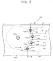
- an image forming apparatus 100 includes, within a housing 101, a paper feeding cassette 110, a paper supplying unit 120, a light scanning unit (LSU) 130, a photosensitive drum 150, an electrifying unit 153, a plurality of developing cartridges 160, a transfer belt 170, a transfer roller 180, and a fusing unit 190.
- a paper feeding cassette 110 includes, within a paper feeding cassette 110, a paper supplying unit 120, a light scanning unit (LSU) 130, a photosensitive drum 150, an electrifying unit 153, a plurality of developing cartridges 160, a transfer belt 170, a transfer roller 180, and a fusing unit 190.
- LSU light scanning unit
- the developing cartridges 160 store toner of a predetermined color (such as black, yellow, magenta, and cyan).
- the developing cartridges 160 each include a developing roller 163 to develop an electrostatic latent image on the photosensitive drum 150.
- a driven connecting part 163b is provided on one end part of a rotational axis 163a of the developing roller 163 in order to receive a rotational power from a driving motor (not shown).
- the driven connecting part 163b rotates in a direction of the rotational axial line of the rotational axis 163a and is provided to engage (or connect to) a driven side assembling part 1421 having a corresponding shape.
- the driven side assembling part 1421 transmits power to the driven connecting part 163b.
- the driven connecting part 163b may, although not necessarily, be provided to have a projected shape, and the driven side assembling part 1421 may be provided to have a caved-in shape.
- the projected shape and caved-in shape are just examples, and the driven connecting part 163b and the driving connecting part may be provided to have other shapes or methods to connect, engage, or latch onto each other, and the caved in shape can instead be on the driven side assembling part 1421, and the projected shape can be on the driven connecting part 163b.
- the electrifying unit 153 supplies a transmission charge to the photosensitive drum 150 to electrify the surface of the photosensitive drum 150 to a uniform transmitting potential.
- the LSU 130 scans light corresponding to image information of, for example, cyan (C) onto the photosensitive drum 150 to form an electrostatic latent image on which a cyan toner will be sprayed.
- a first selectively connecting part (see 1430 in FIG. 6 ) of a power transmission unit (see 140 in FIG. 5 ), to be described later, transmits power to a cyan developing cartridge 160C.
- a developing roller 163C of the cyan developing cartridge 160C supplies cyan toner to the electrostatic latent image to develop the electrostatic latent image, thereby forming a cyan toner image.
- the toner image is transferred to the transfer belt 170.
- cyan (C) and the cyan toner are provided as an example, and other colors may be used.
- magenta, yellow, and black toner images are transferred to the transfer belt 170. Accordingly, a complete color toner image is formed on the transfer belt 170.
- a print medium P stored on a knock-up plate 111 is picked up by a pick-up roller 113 and supplied to a feeding roller 121.
- the feeding roller 121 feeds the print medium P between the transfer belt 170 and the transfer roller 180 so that the color toner image can be transferred on to the print medium P.
- the color toner image on the transfer belt 170 is transferred onto the print medium P, and passes through the fusing part 190 to be fused on the print medium P.
- the image-formed print medium P through this process is discharged to the outside by a discharging roller 123.
- the printing medium P can be paper, transparencies, or any medium on which toner images can be imparted.
- the image forming apparatus 100 further includes a power transmission unit 140 that may be provided between a side frame 103 and an inside frame 107 of the image forming apparatus 100.
- the number of power transmission units 140 provided is equal to the number of developing cartridges 160 provided.
- four developing cartridges 160 may correspond to four power transmission units 140.
- FIGs. 5 and 6 are a perspective view and a sectional view of a power transmission unit 140, respectively, in a state in which a cover (not shown) is opened.
- a cover not shown
- the side frame 103, the rotational axis 163a of the developing roller 163, and the driven connecting part 163b illustrated in FIG. 6 have been omitted in FIG. 5 .
- the power transmission unit 140 includes a transmission member 1410, an assembling member 1420, a first selectively connecting part 1430, and a second selectively connecting part 1440.
- the transmission member 1410 includes a power receiving part 1413 that receives the power.
- the power receiving part 1413 is assembled or contacted with a power distributing gear 106 that distributes a rotational power and is connected to a driving motor (not shown).
- the transmission member 1410 further includes the driving connecting part 1411 that transmits the power to the driven connecting part 163b.
- the power receiving part 1413 is provided to engage the teeth of the power distributing gear 106, and may be provided in the shape of teeth. However, it is understood that methods other than corresponding teeth may be used to engage the power receiving part 1413 with the power distributing gear 106.
- the driving connecting part 1411 is provided to rotate along a rotational axial line A of the rotational axis 163a of the developing roller 163.
- the driving connecting part 1411 may be separated by as much as a predetermined mid-transmitting section H from the driven connecting part 163b.
- the mid-transmitting section H may be determined in consideration of the shape and a moving displacement of the assembling member 1420 (to be described later) in relation to the rotational axial line A, an amount of elasticity of an elastic member 1450, and the shape of the first selectively connecting part 1430.
- the driving connecting part 1411 is illustrated to have a square-sectional projected shape in FIG. 5 , but it is not limited thereto and may be provided in any shape so long as the driving connecting part 1411 can transmit the rotational power to a driving side assembling part 1423 (to be described later) in the direction of the rotational axial line A.
- a driving side assembling part 1423 to be described later
- In the inside of the driving connecting part 1411 may be provided an elastic member inserting hole into which the elastic member 1450 is inserted.
- the assembling member 1420 is provided in the mid-transmitting section H to move in the direction of the rotational axial line A.
- a driven side assembling part 1421 that engages and disengages with/from the driven connecting part 163b in the direction of the rotational axial line A.
- the driving side assembling part 1423 that engages and disengages with/from the driving connecting part 1411 of the transmission member 1410.
- a driven connecting part inserting hole 1421a into which the driven connecting part 163b can be inserted is provided in the driven side assembling part 1421.
- a driving connecting part inserting hole (see 1423a in FIG. 7A ) into which the driving connecting part 1411 can be inserted is provided in the driving side assembling part 1423.
- At least one of the driven side assembling part 1421 and the driving side assembling part 1423 may be provided as a female coupling having a caved-in shape, and the driven connecting part 163b and the driving connecting part 1411 may be provided as a male coupling having a projected shape, as necessary.
- the driven side assembling part 1421 and/or the driving side assembling part 1423 may be provided as a male coupling having a projected shape
- the driven connecting part 163b and/or the driving connecting part 1411 may be provided as a female coupling having a caved-in shape.
- a direction of the driving connecting part 1411 moving toward the driven connecting part 163b is described as an upward direction
- a direction of the driving connecting part 1411 separating from the driven connecting part 163b is described as a downward direction.
- other directions may be applied depending on the relative configuration of the driving connecting part 1411 and the driven connecting part 163b.
- the second selectively connecting part 1440 includes a first selectively connecting member 1441 and a second selectively connecting member 1443.
- the second selectively connecting part 1440 enables the assembling member 1420 to move upward and downward along the rotational axial line A so that the driven side assembling part 1421 of the assembling member 1420 can selectively engage (or connect) and disengage (or separate) with/from the driven connecting part 163b.
- the first selectively connecting member 1441 may include a hitching part (not shown) that is hitched on a hitching projection 103a of the side frame 103 to prevent the first selectively connecting member 1441 from being separated toward the driven connecting part 163b.
- the first selectively connecting member 1441 is provided to rotate.
- the first selectively connecting member 1441 further includes a circumference cam 1441a that is projected from a circumference of the first selectively connecting member 1441 in the direction of the rotational axial line A to a side of the second selectively connecting member 1443.
- the first selectively connecting member 1441 may also include a force operating part 1441b to receive a rotational moment from an outside source.
- the force operating part 1441b may include a link plate inserting projection 1441b1, which is projected from an external side of the first selectively connecting member 1441 to be inserted into an inserting hole 108b of a link plate 108 to be described later.
- the link plate 108 has an inserting projection 108a, and the inserting projection 108a is inserted into an inserting hole 109a of a cover connecting rod 109 that moves in engagement with an opening and a closing of a cover (not shown).
- the link plate 108 is provided to rotate with respect to a stud 105 in parallel with the rotational axial line A. Accordingly, the link plate 108 rotates in forward and reverse directions with respect to the stud 105 if the cover is opened or closed.
- the number of inserting holes 108b of the link plate 108 is provided to correspond to the number of developing rollers 163 of the developing cartridges 160 that require power transmission. That is, for example, if there are four developing rollers 163, then four inserting holes 108b are provided. Moreover, the power transmission unit 140 may be provided in each position of the inserting holes 108b. However, for convenience's sake, only one of them is illustrated in the drawing.
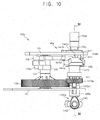
- the second selectively connecting member 1443 is provided to move together with the assembling member 1420. To do so, a selectively connecting member connecting part 1425 is extended from the driving side assembling part 1423 of the assembling member 1420 in a radial direction to contact an assembling member connecting part 1443b of the second selectively connecting member 1443. Also, the second selectively connecting member 1443 may include a guide groove part 1443c (illustrated in FIG. 10 ) projected from an external side. The guide groove part 1443c is inserted into the guide projection 103b projected from the side frame 103 to the rotational axial line A on the side of the second selectively connecting member 1443 to enable the selectively connecting member 1443 to move upward and downward along the guide projection 103b.
- a guide groove part 1443c illustrated in FIG. 10
- the second selectively connecting member 1443 includes a circumference cam profile 1443a that reciprocally operates in contact with the circumference cam 1441a in the rotational axial line A of the first selectively connecting member 1441.
- the circumference cam 1441a and the circumference cam profile 1443a enable the second selectively connecting member 1443 to approach and separate from the driven connecting part 163b according to the rotational direction of the first selectively connecting member 1441. That is, as the first selectively connecting member 1441 rotates in a forward rotating direction E, the circumference cam 1441a rotates in the forward rotating direction E.
- a sliding surface 1443a1 of the circumference cam profile 1443a is contacted with the circumference cam 1441a and the second selectively connecting member 1443 gradually rotates in an upward direction B.
- the second selectively connecting member 1443 gradually rotates to move in the upward direction B until the second selectively connecting member 1443 contacts the first selectively connecting member 1441 and is prevented from moving in the upward direction B.
- the second selectively connecting member 1443 may be limited to rotate and move in the upward direction B due to contact by the circumference cam 1441a with a rotation restricting surface 1443a2 of the circumference cam profile 1443a.
- the second selectively connecting member 1443 may be limited in rotating or moving in the upward direction B in various ways.
- the driven side assembling part 1421 of the assembling member 1420 and the driven connecting part 163b engage each other in a state that the second selectively connecting member 1443 has completed a rotation or movement in the upward direction (for example, when the circumference cam 1441a and the rotation restricting surface 1443a2 are in contact with each other).
- the circumference cam 1441a and the circumference cam profile 1443a may be provided in various shapes in addition to that illustrated in the drawings.
- the first selectively connecting member 1441 rotates in a reverse direction with respect to the forward rotating direction E when the first selectively connecting member 1441 and the second selectively connecting member 1443 are in contact (as described above), the first selectively connecting member 1441 and the second selectively connecting member 1443 separate from each other by as much as a projected length of the circumference cam 1441a, and accordingly, the driven side assembling part 1421 disengages from the driven connecting part 163b. Therefore, the second selectively connecting part 1440 can selectively transmit the power of the assembling member 1420 to the driven connecting part 163b. Furthermore, the first selectively connecting part 1430 (to be described later) can selectively transmit the power of the transmission member 1410 to the assembling member 1420. Also, the first selectively connecting part 1430 and the second selectively connecting part 1440 may selectively connect the power between each other.
- the first selectively connecting part 1430 enables the transmission member 1410 to selectively move upward or downward along the rotational axial line A, and the driving side assembling part 1423 of the assembling member 1420 and the driving connecting part 1411 of the transmission member 1410 to engage (or connect) and disengage (or separate) with/from each other. Accordingly, the rotational power transmitted from the power distributing gear 106 to the transmission member 1410 is selectively transmitted to the assembling member 1420.
- the first selectively connecting part 1430 may include a switching cam 1431, a switching cam axis 1432, and a cam medium member 1435. If the switching cam 1431 directly contacts the transmission member 1410 to enable the transmission member 1410 to move upward and downward in the direction of the rotational axial line A, the cam medium member 1435 may be omitted. In the inside frame 107 is formed a through hole 107a through which the cam medium member 1435 may move upward and downward. The number and the shape of the switching cam 1431 may be properly determined according to the number of the developing cartridges 160 that need power transmitted thereto (for example, four). Meanwhile, the first selectively connecting part 1430 may include a solenoid (not shown) to perform the above-described function. A controller (not shown) may be further provided so as to control the rotating direction or speed of the switching cam 1431, and power to drive the switching cam 1431, as necessary.
- a linear motor (not shown) may be used to move at least one of the transmission member 1410 and the assembling member 1420 along the direction of the rotational axial line A, as necessary. It is understood that if the transmission member 1410 and the assembling member 1420 can be moved along the direction of the rotational axial line A (for example, if the linear motor can be reversely-operated), then the first selectively connecting part 1430 and/or the second selectively connecting part 1440 may be omitted.
- the power transmission unit 140 may further include the elastic member 1450.
- the elastic member 1450 is provided between the transmission member 1410 and the assembling member 1420, and applies an elastic force in a direction to separate the transmission member 1410 from the assembling member 1420.
- the assembling member 1420 may be elastically pressurized toward the driven connecting part 163b, and the transmission member 1410 may be elastically pressurized toward the switching cam 1431.
- FIGs. 7A and 7B are sectional views illustrating a position where power is transmitted and a position where power is blocked, respectively, between the transmission member 1410 and the assembling member 1420 according to the rotation of the switching cam 1431 of the first selectively connecting part 1430.
- the cover (not shown) is closed and the second selectively connecting part 1440 has moved the assembling member 1420 to rotate so that the driven side assembling part 1421 of the assembling member 1420 engages or contacts the driven connecting part 163b of the developing roller (see 163 in FIG. 2 ).
- An operating process opening and closing the cover will be described later. Accordingly, as the driving connecting part 1411 of the transmission member 1410 and the driving side assembling part 1423 of the assembling member 1420 are engaged ( FIG. 7A ) and disengaged ( FIG. 7B ), the power is transmitted and blocked, respectively, to the developing roller 163.
- the switching cam 1431 of the first selectively connecting part 1430 pushes up the cam medium member 1435 to engage the driving connecting part 1411 with the driving side assembling part 1423.
- the power is transmitted from the power distributing gear 106 to the assembling member 1420 via the transmission member 1410.
- the rotational axis 163a having the driven connecting part 163b rotates to drive the developing cartridges 160.
- the elastic member 1450 elastically pressurizes the assembling member 1420 toward the driven connecting part 163b and/or the transmission member 1410 downwardly moves due to a rotation of the switching cam 1431, the driving side assembling part 1423 of the assembling member 1420 and the driving connecting part 1411 of the transmission member 1410 disengage from each other. As a result, the power is not transmitted from the power distributing gear 106 to the assembling member 1420, therefore blocking the power transmission to the developing cartridges 160.
- the elastic member 1450 may be omitted, and the assembling member 1420 may be pressured by other methods (such as electronically) or may not be pressured while the transmission member 1410 moves up and down according to a rotation of the switching cam 1431.
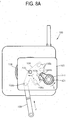
- FIGs. 8A is a plane view of the power transmission unit 140 in a state that the cover is opened
- FIG. 8B is a plane view of the power transmission unit 140 in a state that the cover is closed.
- a sectional view of the power transmission unit 140 in a state in FIG. 8A is the same as that illustrated in FIG. 6 .
- the first selectively connecting member 1441 rotates in the forward direction E, the assembling member 1420 upwardly moves in the direction of the rotational axial line A.
- the driven connecting part 163b and the driven side assembling part 1421 of the assembling member 1420 engage or contact each other, and the assembling member 1420 and the developing roller 163 are in a state capable of rotating together. Therefore, the first selectively connecting member 1441 determines whether the power is transmitted from the power distributing gear 106 to the developing roller 163.
- the cover connecting rod 109, the link plate 108 and the first selectively connecting member 1441 are reversely moved from the state in FIG. 8B to the state in FIG. 8A when the cover is opened during a printing process of the image forming apparatus 100.
- the driven connecting part 163b and the driven side assembling part 1421 of the assembling member 1420 disengage and the power transmission to the developing roller 163 is blocked regardless of the operation of the first selectively connecting member 1441.
- the power transmission unit 140 is provided to drive one of the other three developing cartridges 160, the user can transmit and block the power to the four developing cartridges 160 by opening and closing the cover. Accordingly, if the user opens the cover so as to extract the developing cartridges 160 from the inside of the image forming apparatus 100, the power transmission is automatically blocked by an engagement of the developing cartridges 160 with the cover, thereby enhancing the user's convenience.
- the developing roller 163 of the developing cartridges 160 can be more precisely and stably driven.
- An image forming apparatus includes a power transmission unit having a mid-medium member.
- the detailed description of the other components will be omitted they are the same as the embodiment described with reference to FIGs. 2-8 .
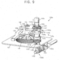
- FIGs. 9 to 11 illustrate the power transmission unit 140a including the mid-medium member 1470 in a state that the cover is opened.
- the power transmission unit 140a according to another embodiment of the present invention includes a transmission member 1410a, an assembling member 1420a, a first selectively connecting part 1430a, a second selectively connecting part 1440a, and the mid-medium member 1470 that is provided between the transmission member 1410a and the assembling member 1420a.
- the transmission member 1410a includes a through hole 1415 inside which a center supporting member 1460 is inserted along a rotational axial line A.
- a washer 1480 may be provided in a lower end part of the transmission member 1410a to prevent the transmission member 1410a from being worn out by a friction between the transmission member 1410a and a cam medium member 1435a.
- a driving side assembling part 1423a of the assembling member 1420a is provided in the shape of a male coupling in comparison with a female coupling shape of the driving side assembling part 1423 ( FIG. 6 ), and engages and disengages a first medium assembling part 1471 of the mid-medium member 1470.
- the cam medium member 1435a of the first selectively connecting part 1430a includes a flange 1435al separated along the circumference so that an inside frame 107 can support the center supporting member 1460.
- the inside frame 107 is formed the through hole (see 107b in FIGs. 9 and 11 ) corresponding to the shape of the flange 1435a1 so that the flange 1435a1 can thoroughly rotate upward and downward. It is understood that the upward and downward represent directions toward and away from, respectively, the developing cartridge 160.
- the center supporting member 1460 may be provided as a stud having the rotational axial line A as a centering line.
- the center supporting member 1460 passes through the transmission member 1410a and the mid-medium member 1470 to more stably support the rotational movement of the transmission member 1410a and the mid-medium member 1470 with respect to the rotational axial line A.
- the center supporting member 1460 is fixedly coupled with the inside frame 107, such that the transmission member 1410a and the mid-medium member 1470 can slide along the center supporting member 1460.
- the center supporting member 1460 may be provided in various shapes to support the rotation of the transmission member 1410a and the mid-medium member 1470. However, it is understood that according to other aspects of the present invention, the center supporting member 1460 may be omitted, as necessary.
- the mid-medium member 1470 includes the first medium assembling part 1471 that engages and disengages the driving side assembling part 1423a of the assembling member 1420a along the rotational axial line A, and a second medium assembling part 1473 that always engages the driving connecting part 1411 of the transmission member 1410a.
- the mid-medium member 1470 rotates or moves upward and downward while connected to or engaging the transmission member 1410a if the transmission member 1410a rotates or moves upward and downward along the rotational axial line A. That is, if the first selectively connecting part 1430a enables the transmission member 1410a to rotate or move downward along the rotational axial line A, the mid-medium member 1470 also rotates or moves downward with the transmission member 1410a. Accordingly, the first medium assembling part 1471 disengages from the driving side assembling part 1423a of the assembling member 1420a.
- the first selectively connecting part 1430a enables the transmission member 1410a to rotate or move upward along the rotational axial line A
- the first medium assembling part 1471 engages the driving side assembling part 1423a of the assembling member 1420a in the direction of the rotational axial line A.
- a first elastic member 1450a and a second elastic member 1450b are provided between the assembling member 1420a and the mid-medium member 1470 and between the mid-medium member 1470 and transmission member 1410a, respectively.
- An elasticity of the second elastic member 1450b may be greater than an elasticity of the first elastic member 1450a so as to elastically pressurize the second selectively connecting part 1440 in the upward direction.
- first elastic member 1450a and the second elastic member 1450b may be provided to have larger inside diameter than an external diameter of the center supporting member 1460 so that the mid-medium member 1470 and the transmission member 1410a movement may not be hindered by an interference from an interaction of the first elastic member 1450a or the second elastic member 1450b with the center supporting member 1460.
- a first selectively connecting member 1441 of the second selectively connecting part 1440 rotates in a forward direction E and a circumference cam 1441 and the circumference cam profile 1443 are reciprocally operated. Since the elasticity F1 of the second elastic member 1450b is greater than the elasticity F2 of the first elastic member 1450a, the second selectively connecting member 1443 enables the assembling member 1420a to rotate in an upward direction B. Accordingly, a driven side assembling part 1421 of the assembling member 1420a engages a driven connecting part 163b in the direction of the rotational axial line A.
- the first medium assembling part 1471 of the mid-medium member 1470 engages and disengages the driving side assembling part 1423a according to the first selectively connecting part 1430a in order to transmit or block the power of a power distributing gear 106 to/from developing roller 163.
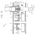
- FIGs. 12 and 13 are sectional views of a power transmission unit where the cover is opened and closed, respectively.
- the transmission member 1410 and the driving side assembling part 1423 of the assembling member 1420 are coupled to each other by the first selectively connecting part 1430.
- the image forming apparatus 100b includes a second selectively connecting part 1440a, different from the second selectively connecting parts 1440 of the embodiments described with reference to FIGs. 2 through 11 .
- the second selectively connecting parts 1440a includes a first selectively connecting member 1446 and a second selectively connecting member 1445 that are formed integrally with a side frame 104.
- the second selectively connecting member 1445 has a cylindrical shape and is formed with a circumference cam profile 1445a.
- the circumference cam profile 1445a approaches and separates from a circumference cam 1446a of the first selectively connecting member 1446 as the second selectively connecting member 1445 rotates in forward and reverse directions while contacting the circumference cam 1446a of the first selectively connecting member 1446. Accordingly, as shown in FIG. 13 , the assembling member 1420 engages the driven connecting part 163b as the second selectively connecting member 1445 approaches the first selectively connecting member 1446. In contrast, the assembling member 1420 disengages from the driven connecting member 163b as the second selectively connecting member 1445 separates from the first selectively connecting member 1446.
- the second selectively connecting part 1440a illustrated in FIGs. 12 and 13 has the same functionality as the second selectively connecting parts 1440 illustrated in FIGs. 2 through 11 in that the second selectively connecting part 1440a engages and disengages the assembling member 1420 with the driven connecting member 163b.
- the second selectively connecting member 1445 illustrated in FIGs. 12 and 13 has no guide groove part. Accordingly, the side frame 104 also has no guide projection to be inserted in the guide groove part.
- the second selectively connecting member 1445 includes a force operating part 1445c to receive a rotational moment while interlocking with an opening and/or closing of the cover (not shown).
- the force operating part 1445c includes a link plate inserting projection 1445c1 to be inserted into the inserting hole 108b of the link plate 108. Accordingly, the second selectively connecting member 1445 rotates in forward and reverse directions while interlocking with the opening and/or closing of the cover, thereby causing the driven side assembling part 1421 of the assembling member 1420 to engage with and disengage from the driven connecting part 163b.
- the link plate inserting projection 1445c1 has a proper height to receive the rotational moment even though the second selectively connecting member 1445 moves along the rotational axial line A.
- the first selectively connecting member 1446 and the side frame 104 are formed as a single body, and the guide projection 103b and the guide groove part 1443c are not included, so that the structure is simplified.
- the developing roller has been exemplified as the driven rotational body in the present description.
- the power transmission unit according to aspects of the present invention may be applied to other rotational bodies.
- a multi-pass type electrophotographic image forming apparatus using one photosensitive drum and one light scanning unit has been exemplified.
- the power transmitting unit according to aspects of the present invention may be applied to other image forming apparatuses having rotational bodies.
- the image forming apparatus and the power transmission unit thereof have the following advantages.
- Third, the impact applied to the developing cartridge through the developing roller can be minimized when the developing cartridge is mounted and detached.
- Fourth, the power transmission and the blocking of power to the developing roller are performed simultaneously while opening and closing the cover, thereby enhancing a user's convenience.
Landscapes
- Physics & Mathematics (AREA)
- General Physics & Mathematics (AREA)
- Electrophotography Configuration And Component (AREA)
Claims (13)
- Bilderzeugungsvorrichtung, aufweisend:ein angetriebenes Rotationsgehäuse, das von der Bilderzeugungsvorrichtung lösbar ist und ein angetriebenes Verbindungsteil (163b) aufweist;ein Übertragungselement (1410), das zum Aufnehmen einer Rotationskraft eingerichtet ist und ein antreibendes Verbindungsteil (1411) aufweist, welches entlang einer Richtung einer Rotationsachsenlinie des angetriebenen Rotationsgehäuses bereitgestellt ist; undein Montageelement (1420), das zum Aufnehmen der Rotationskraft vom Übertragungselement (1410) eingerichtet ist, um die Rotationskraft auf das angetriebene Rotationsgehäuse zu übertragen, um das angetriebene Rotationsgehäuse zu rotieren, und Folgendes aufweist:ein antriebsseitiges Montageteil (1421), eingerichtet zum Verbinden mit dem angetriebenen Verbindungsteil (163b), undein antriebsseitiges Montageteil (1423), eingerichtet zum Verbinden mit dem antreibenden Verbindungsteil (1411);dadurch gekennzeichnet, dass die Bilderzeugungsvorrichtung ferner Folgendes aufweist: ein erstes selektiv wirkendes Verbindungsteil (1430), eingerichtet zum selektiven Bewegen des Übertragungselements (1410) entlang der Richtung der Rotationsachsenlinie, so dass das angetriebene Verbindungsteil (1411) zum Eingriff mit oder Lösen von dem antriebsseitigen Montageteil (1423) des Montageelements (1420) betätigt werden kann; und ferner aufweisend ein zweites selektiv wirkendes Verbindungsteil (1440), eingerichtet zum selektiven Bewegen des Montageelements (1420) entlang der Richtung der Drehachsenlinie, so dass das antriebsseitige Montageteil (1421) zum Eingriff mit oder Lösen von dem angetriebenen Verbindungsteil (163b) des angetriebenen Rotationsgehäuses bewegt werden kann.
- Bilderzeugungsvorrichtung nach Anspruch 1, wobei das Übertragungselement (1410) einen Kraft aufnehmenden Teil zur Aufnahme der Rotationskraft aufweist und ferner einen antreibenden Teil zum Antreiben des Kraft aufnehmenden Teils aufweist.
- Bilderzeugungsvorrichtung nach einem der vorhergehenden Ansprüche, wobei das erste selektiv wirkende Verbindungsteil (1430) einen Nocken und/oder ein Solenoid aufweist.
- Bilderzeugungsvorrichtung nach einem der vorhergehenden Ansprüche, ferner aufweisend ein Steuergerät zum Steuern des ersten selektiv wirkenden Verbindungsteils (1430) zum Eingriff des antreibenden Verbindungsteils (1411) mit dem antriebsseitigen Montageteil (1423), wenn das angetriebene Rotationsgehäuse die Rotationskraft benötigt.
- Bilderzeugungsvorrichtung nach einem der vorhergehenden Ansprüche, wobei das zweite selektiv wirkende Verbindungsteil (1440) Folgendes aufweist:ein erstes selektiv wirkendes Verbindungselement (1441) zum Rotieren um die Drehachsenlinie; undein zweites selektiv wirkendes Verbindungselement (1443), verbunden mit dem Montageelement (1420) auf solche Weise, dass das zweite selektiv wirkende Verbindungselement (1443) eingerichtet ist, um sich zusammen mit dem Montageelement (1420) in Richtung hin zum oder weg vom angetriebenen Verbindungsteil (163b) gemäß einer Richtung, in der das erste selektiv wirkende Verbindungselement (1441) rotiert, zu bewegen.
- Bilderzeugungsvorrichtung nach Anspruch 5, wobei das antriebsseitige Montageteil (1421) eingerichtet ist zum Bewirken eines Eingriffs des angetriebenen Verbindungsteils (163b), wenn das erste selektiv wirkende Verbindungselement (1441) in einer ersten Richtung rotiert, bis sich das zweite selektiv wirkende Verbindungselement (1442) nicht mehr in Richtung zum angetriebenen Verbindungsteil (163b) bewegen kann.
- Bilderzeugungsvorrichtung nach Anspruch 5 oder 6, wobei:das erste selektiv wirkende Verbindungselement (1441) oder das zweite selektiv wirkende Verbindungselement (1443) einen entlang einem Umkreis um die Drehachsenlinie bereitgestellten Nocken aufweist, undein anderes des ersten selektiv wirkenden Verbindungselements (1441) und zweiten selektiv wirkenden Verbindungselements (1443) ein Nockenprofil aufweist, das eingerichtet ist, um bei Kontakt mit dem Nocken umgekehrt zu wirken.
- Bilderzeugungsvorrichtung nach einem der Ansprüche 5 bis 7, wobei das zweite selektiv wirkende Verbindungsteil (1440) ein Kraftbetätigungsteil (1445c) aufweist, um ein Drehmoment von einer äußeren Quelle aufzunehmen, das dem ersten selektiv wirkenden Verbindungselement (1441) ein Drehen ermöglicht.
- Bilderzeugungsvorrichtung nach einem der Ansprüche 5 bis 8, ferner aufweisend:einen Deckel, der zum Öffnen und Schließen eingerichtet ist,wobei das erste selektiv wirkende Verbindungselement (1441) eingerichtet ist zum Rotieren in einer ersten Richtung, wenn sich der Deckel schließt, und zum Rotieren in einer zweiten Richtung, wenn sich der Deckel öffnet.
- Bilderzeugungsvorrichtung nach einem der vorhergehenden Ansprüche, ferner aufweisend ein zwischen dem Montageelement (1420) und dem Übertragungselement (1410) bereitgestelltes elastisches Element zum Anbringen einer elastischen Kraft in einer Richtung zum Trennen des Montageelements (1420) und des Übertragungselements (1410) voneinander.
- Bilderzeugungsvorrichtung nach einem der vorhergehenden Ansprüche, wobei das antreibende Verbindungsteil (1411) und das angetriebene Verbindungsteil (163b) in einem Zustand, wenn das antriebsseitige Montageteil (1421) nicht mit dem angetriebenen Verbindungsteil (163b) verbunden ist, um einen im Voraus festgelegten Abstand voneinander getrennt sind.
- Bilderzeugungsvorrichtung nach einem der vorhergehenden Ansprüche, ferner aufweisend:ein mittig-mittleres Element (1470), bereitgestellt zwischen dem Übertragungselement (1410) und dem Montageelement (1420), und aufweisend:ein erstes mittleres Montageteil (1471) zum Bewirken von Eingriff mit oder Lösen vom antriebsseitigen Montageteil (1423) entsprechend einer Bewegung des Übertragungselements (1410); undein zweites mittleres Montageteil (1473), um immer einen Eingriff des antreibenden Verbindungsteils (1411) des Übertragungselements (1410) zu bewirken.
- Bilderzeugungsvorrichtung nach einem der vorhergehenden Ansprüche, ferner aufweisend einen Bildempfänger, und wobei das angetriebene Rotationsgehäuse mehrere Entwicklungswalzen zum Entwickeln des Bildempfängers aufweist.
Applications Claiming Priority (1)
| Application Number | Priority Date | Filing Date | Title |
|---|---|---|---|
| KR1020060117708A KR101324184B1 (ko) | 2006-11-27 | 2006-11-27 | 화상형성장치 및 그 동력전달유닛 |
Publications (2)
| Publication Number | Publication Date |
|---|---|
| EP1925985A1 EP1925985A1 (de) | 2008-05-28 |
| EP1925985B1 true EP1925985B1 (de) | 2014-01-08 |
Family
ID=39068609
Family Applications (1)
| Application Number | Title | Priority Date | Filing Date |
|---|---|---|---|
| EP07120496.0A Ceased EP1925985B1 (de) | 2006-11-27 | 2007-11-12 | Bilderzeugungsvorrichtung und Leistungsübertragungseinheit dafür |
Country Status (4)
| Country | Link |
|---|---|
| US (1) | US7761036B2 (de) |
| EP (1) | EP1925985B1 (de) |
| KR (1) | KR101324184B1 (de) |
| CN (1) | CN101192024B (de) |
Families Citing this family (5)
| Publication number | Priority date | Publication date | Assignee | Title |
|---|---|---|---|---|
| KR101579738B1 (ko) * | 2010-12-23 | 2016-01-05 | 삼성전자주식회사 | 현상기 및 이를 채용한 화상형성장치 |
| KR101848386B1 (ko) * | 2011-10-12 | 2018-04-13 | 에스프린팅솔루션 주식회사 | 화상형성장치 |
| KR101842614B1 (ko) * | 2011-11-21 | 2018-03-27 | 에스프린팅솔루션 주식회사 | 멀티패스방식 화상형성장치 |
| CN105676607B (zh) * | 2016-03-31 | 2023-08-11 | 珠海天威飞马打印耗材有限公司 | 显影盒 |
| JP7822764B2 (ja) * | 2021-12-13 | 2026-03-03 | キヤノン株式会社 | 画像形成装置 |
Family Cites Families (12)
| Publication number | Priority date | Publication date | Assignee | Title |
|---|---|---|---|---|
| JP2701965B2 (ja) | 1990-07-19 | 1998-01-21 | キヤノン株式会社 | カラー画像形成装置 |
| JP2000206754A (ja) * | 1996-03-14 | 2000-07-28 | Matsushita Electric Ind Co Ltd | カラ―画像形成装置 |
| US6240266B1 (en) * | 1996-03-21 | 2001-05-29 | Canon Kabushiki Kaisha | Process cartridge and drum mount for photosensitive drum |
| JP3466831B2 (ja) * | 1996-08-29 | 2003-11-17 | キヤノン株式会社 | プロセスカートリッジ及び電子写真画像形成装置 |
| JP3689504B2 (ja) * | 1996-09-26 | 2005-08-31 | キヤノン株式会社 | 電子写真画像形成装置 |
| JP3893222B2 (ja) * | 1998-08-31 | 2007-03-14 | キヤノン株式会社 | シャッターピン及び現像カートリッジ |
| JP2000214654A (ja) | 1999-01-20 | 2000-08-04 | Matsushita Electric Ind Co Ltd | カラ―画像形成装置 |
| JP3821199B2 (ja) | 1999-11-05 | 2006-09-13 | セイコーエプソン株式会社 | 画像形成装置 |
| JP4046933B2 (ja) * | 2000-08-02 | 2008-02-13 | キヤノン株式会社 | 駆動伝達装置及びこれを備える画像形成装置 |
| JP3667243B2 (ja) | 2000-12-01 | 2005-07-06 | キヤノン株式会社 | プロセスカートリッジ及びプロセスカートリッジの装着機構及び電子写真画像形成装置 |
| JP2005257875A (ja) | 2004-03-10 | 2005-09-22 | Seiko Epson Corp | 画像形成装置 |
| JP4710476B2 (ja) | 2004-10-28 | 2011-06-29 | ブラザー工業株式会社 | 画像形成装置 |
-
2006
- 2006-11-27 KR KR1020060117708A patent/KR101324184B1/ko not_active Expired - Fee Related
-
2007
- 2007-10-24 US US11/877,995 patent/US7761036B2/en not_active Expired - Fee Related
- 2007-11-12 EP EP07120496.0A patent/EP1925985B1/de not_active Ceased
- 2007-11-27 CN CN2007101937755A patent/CN101192024B/zh not_active Expired - Fee Related
Also Published As
| Publication number | Publication date |
|---|---|
| CN101192024B (zh) | 2011-03-30 |
| EP1925985A1 (de) | 2008-05-28 |
| CN101192024A (zh) | 2008-06-04 |
| US7761036B2 (en) | 2010-07-20 |
| US20080124129A1 (en) | 2008-05-29 |
| KR20080047805A (ko) | 2008-05-30 |
| KR101324184B1 (ko) | 2013-11-06 |
Similar Documents
| Publication | Publication Date | Title |
|---|---|---|
| US11460802B2 (en) | Process cartridge and image forming apparatus | |
| US8238795B2 (en) | Image forming apparatus | |
| US6795671B2 (en) | Image forming apparatus featuring switchable, contact and spaced, clutch-operated developing units | |
| US8238799B2 (en) | Cartridge alignment member for aligning with a developer unit in an electrophotographic image forming device | |
| US8824919B2 (en) | Electrophotographic image forming apparatus having rotation-regulated process cartridge | |
| US9971300B2 (en) | Cartridge and electrophotographic image forming apparatus including the same | |
| US7835666B2 (en) | Image forming apparatus and power transmission unit thereof | |
| JP3799227B2 (ja) | 画像形成装置 | |
| US7272341B2 (en) | Electrophotographic image forming apparatus | |
| US7336916B2 (en) | Electrophotographic image forming apparatus | |
| EP1925985B1 (de) | Bilderzeugungsvorrichtung und Leistungsübertragungseinheit dafür | |
| JP7246902B2 (ja) | 画像形成装置 | |
| US10466621B2 (en) | Developing cartridge and electrophotographic image forming apparatus employing same | |
| US7680441B2 (en) | Image forming apparatus | |
| EP1757994A2 (de) | Kraftübertragungsgerät für Entwicklungseinheit und Bilderzeugungsgerät |
Legal Events
| Date | Code | Title | Description |
|---|---|---|---|
| PUAI | Public reference made under article 153(3) epc to a published international application that has entered the european phase |
Free format text: ORIGINAL CODE: 0009012 |
|
| AK | Designated contracting states |
Kind code of ref document: A1 Designated state(s): AT BE BG CH CY CZ DE DK EE ES FI FR GB GR HU IE IS IT LI LT LU LV MC MT NL PL PT RO SE SI SK TR |
|
| AX | Request for extension of the european patent |
Extension state: AL BA HR MK RS |
|
| 17P | Request for examination filed |
Effective date: 20081027 |
|
| 17Q | First examination report despatched |
Effective date: 20081127 |
|
| AKX | Designation fees paid |
Designated state(s): DE FR GB NL |
|
| RAP1 | Party data changed (applicant data changed or rights of an application transferred) |
Owner name: SAMSUNG ELECTRONICS CO., LTD. |
|
| GRAP | Despatch of communication of intention to grant a patent |
Free format text: ORIGINAL CODE: EPIDOSNIGR1 |
|
| INTG | Intention to grant announced |
Effective date: 20130614 |
|
| GRAS | Grant fee paid |
Free format text: ORIGINAL CODE: EPIDOSNIGR3 |
|
| GRAA | (expected) grant |
Free format text: ORIGINAL CODE: 0009210 |
|
| AK | Designated contracting states |
Kind code of ref document: B1 Designated state(s): DE FR GB NL |
|
| REG | Reference to a national code |
Ref country code: GB Ref legal event code: FG4D |
|
| REG | Reference to a national code |
Ref country code: DE Ref legal event code: R096 Ref document number: 602007034634 Country of ref document: DE Effective date: 20140220 |
|
| REG | Reference to a national code |
Ref country code: NL Ref legal event code: T3 |
|
| REG | Reference to a national code |
Ref country code: DE Ref legal event code: R097 Ref document number: 602007034634 Country of ref document: DE |
|
| PLBE | No opposition filed within time limit |
Free format text: ORIGINAL CODE: 0009261 |
|
| STAA | Information on the status of an ep patent application or granted ep patent |
Free format text: STATUS: NO OPPOSITION FILED WITHIN TIME LIMIT |
|
| 26N | No opposition filed |
Effective date: 20141009 |
|
| REG | Reference to a national code |
Ref country code: DE Ref legal event code: R097 Ref document number: 602007034634 Country of ref document: DE Effective date: 20141009 |
|
| REG | Reference to a national code |
Ref country code: FR Ref legal event code: PLFP Year of fee payment: 10 |
|
| REG | Reference to a national code |
Ref country code: NL Ref legal event code: PD Owner name: S-PRINTING SOLUTION CO., LTD.; KO Free format text: DETAILS ASSIGNMENT: CHANGE OF OWNER(S), ASSIGNMENT; FORMER OWNER NAME: SAMSUNG ELECTRONICS CO., LTD. Effective date: 20170221 |
|
| REG | Reference to a national code |
Ref country code: GB Ref legal event code: 732E Free format text: REGISTERED BETWEEN 20170406 AND 20170412 |
|
| REG | Reference to a national code |
Ref country code: DE Ref legal event code: R081 Ref document number: 602007034634 Country of ref document: DE Owner name: HP PRINTING KOREA CO., LTD., SUWON-SI, KR Free format text: FORMER OWNER: SAMSUNG ELECTRONICS CO., LTD., SUWON, KYONGGI, KR Ref country code: DE Ref legal event code: R081 Ref document number: 602007034634 Country of ref document: DE Owner name: HEWLETT-PACKARD DEVELOPMENT COMPANY, L.P., SPR, US Free format text: FORMER OWNER: SAMSUNG ELECTRONICS CO., LTD., SUWON, KYONGGI, KR Ref country code: DE Ref legal event code: R081 Ref document number: 602007034634 Country of ref document: DE Owner name: S-PRINTING SOLUTION CO., LTD., SUWON-SI, KR Free format text: FORMER OWNER: SAMSUNG ELECTRONICS CO., LTD., SUWON, KYONGGI, KR |
|
| REG | Reference to a national code |
Ref country code: FR Ref legal event code: TP Owner name: S-PRINTING SOLUTION CO., LTD., KR Effective date: 20170912 |
|
| REG | Reference to a national code |
Ref country code: FR Ref legal event code: PLFP Year of fee payment: 11 |
|
| REG | Reference to a national code |
Ref country code: FR Ref legal event code: PLFP Year of fee payment: 12 |
|
| REG | Reference to a national code |
Ref country code: NL Ref legal event code: HC Owner name: HP PRINTING KOREA CO., LTD.; KR Free format text: DETAILS ASSIGNMENT: CHANGE OF OWNER(S), CHANGE OF OWNER(S) NAME; FORMER OWNER NAME: S-PRINTING SOLUTION CO., LTD. Effective date: 20180816 |
|
| REG | Reference to a national code |
Ref country code: DE Ref legal event code: R081 Ref document number: 602007034634 Country of ref document: DE Owner name: HP PRINTING KOREA CO., LTD., SUWON-SI, KR Free format text: FORMER OWNER: S-PRINTING SOLUTION CO., LTD., SUWON-SI, GYEONGGI-DO, KR Ref country code: DE Ref legal event code: R081 Ref document number: 602007034634 Country of ref document: DE Owner name: HEWLETT-PACKARD DEVELOPMENT COMPANY, L.P., SPR, US Free format text: FORMER OWNER: S-PRINTING SOLUTION CO., LTD., SUWON-SI, GYEONGGI-DO, KR |
|
| REG | Reference to a national code |
Ref country code: NL Ref legal event code: PD Owner name: HEWLETT-PACKARD DEVELOPMENT COMPANY, L.P.; US Free format text: DETAILS ASSIGNMENT: CHANGE OF OWNER(S), CHANGE OF LEGAL ENTITY; FORMER OWNER NAME: SAMSUNG ELECTRONICS CO., LTD. Effective date: 20191030 |
|
| REG | Reference to a national code |
Ref country code: DE Ref legal event code: R081 Ref document number: 602007034634 Country of ref document: DE Owner name: HEWLETT-PACKARD DEVELOPMENT COMPANY, L.P., SPR, US Free format text: FORMER OWNER: HP PRINTING KOREA CO., LTD., SUWON-SI, GYEONGGI-DO, KR |
|
| REG | Reference to a national code |
Ref country code: GB Ref legal event code: 732E Free format text: REGISTERED BETWEEN 20191212 AND 20191218 |
|
| PGFP | Annual fee paid to national office [announced via postgrant information from national office to epo] |
Ref country code: NL Payment date: 20201029 Year of fee payment: 14 |
|
| PGFP | Annual fee paid to national office [announced via postgrant information from national office to epo] |
Ref country code: GB Payment date: 20201021 Year of fee payment: 14 Ref country code: FR Payment date: 20201021 Year of fee payment: 14 Ref country code: DE Payment date: 20201020 Year of fee payment: 14 |
|
| REG | Reference to a national code |
Ref country code: DE Ref legal event code: R119 Ref document number: 602007034634 Country of ref document: DE |
|
| REG | Reference to a national code |
Ref country code: NL Ref legal event code: MM Effective date: 20211201 |
|
| GBPC | Gb: european patent ceased through non-payment of renewal fee |
Effective date: 20211112 |
|
| PG25 | Lapsed in a contracting state [announced via postgrant information from national office to epo] |
Ref country code: NL Free format text: LAPSE BECAUSE OF NON-PAYMENT OF DUE FEES Effective date: 20211201 |
|
| PG25 | Lapsed in a contracting state [announced via postgrant information from national office to epo] |
Ref country code: GB Free format text: LAPSE BECAUSE OF NON-PAYMENT OF DUE FEES Effective date: 20211112 Ref country code: DE Free format text: LAPSE BECAUSE OF NON-PAYMENT OF DUE FEES Effective date: 20220601 |
|
| PG25 | Lapsed in a contracting state [announced via postgrant information from national office to epo] |
Ref country code: FR Free format text: LAPSE BECAUSE OF NON-PAYMENT OF DUE FEES Effective date: 20211130 |