EP1925885B1 - Hollow equipment, cooking oven with a hollow equipment and operating method therefore - Google Patents
Hollow equipment, cooking oven with a hollow equipment and operating method therefore Download PDFInfo
- Publication number
- EP1925885B1 EP1925885B1 EP06024497A EP06024497A EP1925885B1 EP 1925885 B1 EP1925885 B1 EP 1925885B1 EP 06024497 A EP06024497 A EP 06024497A EP 06024497 A EP06024497 A EP 06024497A EP 1925885 B1 EP1925885 B1 EP 1925885B1
- Authority
- EP
- European Patent Office
- Prior art keywords
- accessory
- cooking
- heat
- food
- fluid
- Prior art date
- Legal status (The legal status is an assumption and is not a legal conclusion. Google has not performed a legal analysis and makes no representation as to the accuracy of the status listed.)
- Not-in-force
Links
Images


Classifications
-
- F—MECHANICAL ENGINEERING; LIGHTING; HEATING; WEAPONS; BLASTING
- F24—HEATING; RANGES; VENTILATING
- F24C—DOMESTIC STOVES OR RANGES ; DETAILS OF DOMESTIC STOVES OR RANGES, OF GENERAL APPLICATION
- F24C15/00—Details
- F24C15/16—Shelves, racks or trays inside ovens; Supports therefor
-
- F—MECHANICAL ENGINEERING; LIGHTING; HEATING; WEAPONS; BLASTING
- F24—HEATING; RANGES; VENTILATING
- F24C—DOMESTIC STOVES OR RANGES ; DETAILS OF DOMESTIC STOVES OR RANGES, OF GENERAL APPLICATION
- F24C15/00—Details
- F24C15/32—Arrangements of ducts for hot gases, e.g. in or around baking ovens
- F24C15/322—Arrangements of ducts for hot gases, e.g. in or around baking ovens with forced circulation
Definitions
- the invention relates to an accessory according to the preamble of claim 1, a cooking appliance with a cooking chamber, in which such an accessory can be introduced or introduced; and a method of operating such a cooking appliance.
- Cooking utensils for thermal food preparation are well known in the art. Thermal radiation and / or heat conduction are used to transfer heat. Thermal radiation is mainly used in the use of so-called top and bottom heat. In this case, one or more walls of a cooking chamber, for example. Via heating wires brought to an elevated temperature, so that they emit heat radiation. This heat radiation then hits on food and is at least partially absorbed by it, thereby increasing the temperature of the food.
- the energy transfer by heat conduction is of central importance in a hot air operation, steaming and / or grilling of food. When grilling, the food is placed directly on a hot plate or a hot grill. Due to the interstices of the grill can of course also heat radiation for heating the food penetrate through.
- the typical grill patterns come about through contact of the food with a hot carrier material, namely the grill grate.
- a hot carrier material namely the grill grate.
- water condenses on the food to be cooked, thus transferring the condensation heat of the water to the food in addition to the thermal energy of the water gas molecules.
- energy becomes a hot cooking chamber atmosphere transferred to the food.
- the various media for transferring heat to food such as by steam, heat radiation or heat conduction, are usually heated electrically or by burning a liquid or solid fuel.
- Garages with heat accumulators improve the energy input substantially, but must ensure a uniform and rapid distribution of hot air in the oven so as not to cause a negative effect on the food, such as in the form of uneven browning, burned areas or the like.
- a cooking appliance with an energy storage and energy extraction system serves to provide the cooking appliance with very large amounts of energy in the short term, without making very high connection performance of the cooking appliance necessary.
- Energy can be stored for this purpose in the form of thermal, electrical and / or mechanical energy in a heat storage, the charging can be done in times where little or no energy is needed for the heating of the cooking appliance.
- thermal heat energy contained in the cooking space is at least partially transferred to the heat storage and stored there.
- a heater but also a circulation system, a humidity control, a steam generator and / or a cooling unit can be operated, with a measuring and control system is used, with the right dosage of energy and the right one Time to use the energy can be ensured.
- a cooking appliance thus additionally serves to reduce energy consumption.
- a cooking appliance with an electrically heatable heat storage through which an air flow for heating a cooking chamber one or more times can be passed.
- the heat storage channels for this purpose passing channels open into the oven and can be closed by flaps. By closing the flaps, the entry of heat energy from the heat storage can be prevented.
- a disadvantage of this prior art that only hot air from the heat storage is supplied to the cooking chamber. The heat energy from the memory is thus transferred to the food only by convection via the cooking chamber atmosphere.
- the JP 2002 071 138 discloses a cooking appliance in which steam from a steam generator is passed through a high temperature heat storage tank to produce superheated steam. With the help of the heat accumulator so steam is generated, which can condense on food. The disadvantage of this is that the heat can be used to heat the same only by condensation of the steam on the food. Also, a targeted admission of individual levels in the oven is not possible.
- the EP 0 002 784 A1 discloses a H exertluftgarêt, in which a uniform loading of a cooking food to be cooked with hot air is realized in that the flow direction of the circulating air is changed during cooking with a suitable device.
- From the DE 102 20 266 A1 is a support structure for receiving food known, with a large number of food items can be cooked per shelf level. Due to the support structure ensures that the various items to be cooked as closely as possible but still spaced from each other can be introduced into the cooking chamber, so that the circulated in the cooking hot air heats the food on all sides and evenly with heat energy.
- a cooking appliance with a generic accessory comprising a pipe system for the even distribution of steam in a cooking chamber, is from the EP 1 538 396 A1 known.
- the pipe system has a plurality of openings and is connected to a steam generator, so that the steam from the steam generator flows through the pipe system and at the various locations in the cooking chamber distributed from the pipe system exits. This ensures that cooked food placed in the cooking appliance can be supplied with steam uniformly and on all sides. At the same time, a hot air circulation in the cooking chamber can be provided.
- Object of the present invention is to further develop the generic accessories such that in the simplest possible but also variable manner, an energy input in various forms in a food, preferably in different loading levels of the accessories, allows, without causing high costs.
- a cooking appliance with a cooking chamber in which an inventive accessory can be introduced or introduced, supplied with claim 11.
- the invention also relates to a method for operating a cooking appliance according to the invention according to claim 25.
- FIG. 1 shows an inventive accessory in the form of a so-called tray rack 1 for a cooking appliance
- the plug-in ladders 10 may be formed as tubes, perpendicular to which slide rails 20 are mounted, which may be formed, for example, as part-tubes.
- the tubes of the plug-in ladders 10 have openings 30 for supplying a hot air flow and openings 40 for discharging the hot air flow and thus act as air-conducting tubes.
- inserts 50 can be introduced, each having at least one cavity (not shown).
- the cavities in the interior of the inserts 50 are connected to openings 60, which allow entry of air into the slots 50.
- the openings 60 of the inserts 50 can be connected via the tubes of the insertion conductors 10 with the openings 30, namely via openings not shown in the slide rails 20.
- the openings 60 of the inserts 50 may be suitable even for receiving an air flow. Especially suitable in the latter case are funnel-shaped, closable openings, as in FIG FIG. 1 indicated on the left.
- FIG. 1 Is the tray rack 1 according to the invention FIG. 1 in a hot air stream which impinges on the rack frame 1 from the left side, a portion of the hot air flows will enter the openings 30 and / or 60 and from there flow through the interior of the inserts 50.
- the hot air flow can give off part of its thermal energy to the materials from which the inserts 50 are made.
- the at least partially cooled air can then escape through the openings 40 and / or 70 from the rack frame 1, that is, the cooking chamber atmosphere to be supplied again.
- the openings 40 on the in FIG. 1 The right side of the insertion ladders 10 can be used alternatively or cumulatively for introducing the air flow, wherein in the latter case the insertion ladders 10 or the inserts 50 must have further openings which are suitable for directing the air flow from the cavities of the tray rack 1.
- any other gaseous or liquid medium can also be used. If the following is an air flow, the use of a general fluid flow is always possible.
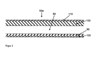
- FIG. 2 shows the cross section of a first inventive insert 50a for the in FIG. 1 shown tray rack 1, with an air gap 80 for passing a hot air flow.
- the underside of the insert 50a forms a poorly heat-conducting layer 90, while the top is made up of a good heat-conducting layer 100.
- a highly thermally conductive material from which the good heat conducting layer 100 may be made is an aluminum alloy capable of passing the thermal energy from the interior of the insert 50a to a food (not shown) located on the top of the food Insert 50a is placed.
- the poorly thermally conductive layer 90 on the underside of the insert 50a according to the invention ensures that the heat is not conducted through the underside as much as possible.
- ceramics and plastics which are only partially suitable for use in a cooking appliance due to lack of robustness, lack of temperature resistance or high manufacturing costs, especially foams or multilayer systems come as material for the poor thermal conductivity layer 90 in question.
- a non-stick coating 110 on the top of a non-stick coating 110 and on the bottom of a coating 120, which hinders thermal heat radiation from the bottom of the insert 50a ago, are provided.
- drawer 50a As well as for all other drawer variants according to the invention, it does not matter whether it has a grid structure, a completely flat structure or another structure, as long as there are continuous openings for an air flow inside.
- a slot 50a is adapted to dissipate heat of a hot air stream flowing therethrough, especially upwards.
- This is one such insert 50a suitable for roasting not shown Gargut when the food is placed directly on top of the same.
- the heat transfer is then given above all by the contact heat of the surface of the insert 50a according to the invention.
- a further layer may also be provided on the upper side of the good heat-conducting layer 100, which layer is well suited for emitting heat radiation in the temperature range used.
- Such a so-called black radiator in contrast to the poorly heat radiating coating 120 on the underside of the insert 50a according to the invention would lead to a high emission of heat radiation on the top.
- a food placed on a grid (not shown) above the tray 50a can be grilled by the heat radiation.
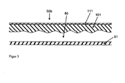
- FIG. 3 shows a second insert 50b according to the invention, which in its construction corresponds to that of FIG. 2 similar.
- the insert 50b has an air gap 80 which is delimited on the one hand by a poorly heat-conducting layer 91 and on the other hand by a good heat-conducting layer 101, a non-stick coating 111 being applied to the latter.
- the insert 50b has, on the one hand, a structure of the surface of the good heat-conducting layer 101 on the side facing the air gap 80, and, on the other hand, no poorly heat-radiating coating is provided on the poorly heat-conducting layer 91.
- connecting webs may also be provided in the interior of the air gap, which serve both to improve the heat conduction and to stabilize the structure.
- connecting webs may also be provided in the interior of the air gap, which serve both to improve the heat conduction and to stabilize the structure.
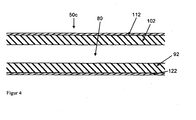
- FIG. 4 shows the cross section of a third inventive insert 50c for generating top and bottom heat.
- both a lower layer 92 and an upper layer 102 which delimit an air gap 80, are made of a good heat-conducting material.
- both the lower layer 92 and the upper layer 102 on the side of the air gap 80 may be provided with a structure (not shown) as shown in FIG FIG. 3 is shown.
- a non-stick coating 112 may be applied to the good heat-conducting layer 102.
- the food can be cooked from above by top heat from the top drawer 50c and bottom by contact heat by resting on the bottom drawer 50c or bottom heat when placing the food on an additional grill (not shown) ) or the like between the shelves 50c are cooked.
- FIG. 5 shows a cross section of a fourth inventive insert 50d for generating top heat.
- the underside consists of a good heat-conducting layer 93, which may be coated with a good heat-radiating material (not shown).
- the upper side consists of a poorly heat-conducting layer 103, on which a poorly heat-radiating layer 113 can be applied.
- the various bays 50a, 50b, 50c, 50d or other bays 50 according to the invention mixed into the slide rails 20 of a tray rack 1 according to the invention.
- a first food to be cooked on a top drawer 50c with contact heat, baked on a subjacent drawer 50a, a second food with top and bottom heat and under a next, underlying drawer 50d a third food only with top heat are applied.
- a variety of other combinations and possibilities are conceivable.
- FIG. 6 shows a cooking appliance 130 with a cooking chamber 140 and a door 150 in a horizontal section.
- an insertion head 10 In the cooking chamber 140 is an insertion head 10 according to the invention with openings 30 for introducing a hot air flow.
- a radial fan 160 To generate the hot air flow is a radial fan 160 which is driven by an engine (not shown) via an axis and is surrounded annularly by a heater 170 in the form of heating coils.
- the radial fan 160 attracts air from the center of the cooking chamber 140 at the height of the axis through a central opening 181 of an air guide plate 180 and accelerates it radially outward, in FIG. 6 up and down.
- a flow is also generated, which is blown along the edge of the cooking chamber 140 along.
- the air flow in the cooking chamber 140 is led into the openings 30 of the insertion ladders 10 according to the invention, driven by the radial fan 160 to get into slots (not shown), as with respect to the FIGS. 2 to 5 can be described described.
- openings not shown then finally leaves the at least partially cooled in the slots air the same and can be reheated by sucking on the radial fan 160 and passing the heater 170 to be used for further heating of the bays and thus not shown food to the same.
- FIG. 7 shows a vertical cross-sectional view of Um Kunststoffgarmelds 205 with inserts 50 according to the invention.
- the cooking device 205 is divided into a technical room 210, a pressure chamber 220 and a cooking chamber 230, in which the bays 50 are located.
- all the electronics (not shown) for controlling the cooking appliance 205 are located in the technology room 210.
- the fan wheel 250 which is driven by the motor 240 via an axis 260, is located in the pressure space 220 and generates an outward air flow, so in the upper and lower regions of the pressure chamber 220, an overpressure.
- the air flows past the helices of a heater 270, which is arranged in the form of a spiral around the fan 250.
- the heater 270 can be an electrical resistance heater or even the tubes of a heat exchanger in which combustion gases flow.
- the heated air flows during operation of the fan 250 from the pressure chamber 220 via openings 280, which leaves an air baffle 290 between the inner walls 300 of the cooking chamber 230 and its edges open in the cooking chamber 230 and is from the cooking chamber 230 via a central opening 285 of Air baffle 290 sucked back into the pressure chamber 220.
- the cooking appliance 205 further has an additional, not shown heat source, for example in the form of a heat accumulator (not shown), which has a known per se.
- a heat accumulator (not shown)
- From the heat storage can be specifically introduced by means of a ventilation or pumping system (not shown) via a coupling point 310, which may be closed, a hot fluid in the cooking chamber 230.
- a ventilation or pumping system (not shown) via a coupling point 310, which may be closed, a hot fluid in the cooking chamber 230.
- a heating or pumping system not shown
- a coupling point 310 which may be closed
- a hot fluid in the cooking chamber 230 Through feeders 320 inserts 50 of a tray rack in the oven 230 can be traversed by the hot fluid. If the fluid is air, then this air can easily escape from the slots after warming them back into the cooking chamber 230. If the fluid is a liquid, then it must be returned via leads (not shown) to the heat source or the heat
- FIG. 8 shows an inventive accessory in a cooking chamber 330 of a combined hot air and Dampfgarilless 325.
- a device 325 differs mainly by a steam generator 340 in a technical room 350, with the steam can be transported through an opening 360 in a pressure chamber 370, of the previously with reference to FIG. 7
- a heater 380 to produce hot air again serves a heater 380, at the air by means of a fan 390, which is driven by a motor 400 in the engine room 350 via an axis 410, air is passed.
- the rotation of the fan wheel 390 formed as a radial fan creates an overpressure around the fan wheel 390, so that the heated air can only enter the cooking chamber 330 via narrow free areas 420 between an air guide plate 430 and inner cooking space 440.
- the air baffle 430 thus serves mainly to ensure a uniform flow of air in the cooking chamber 330 and so act on the bays 50 regardless of the respective slot height evenly with thermal energy.
- the air guide plate 430 has a central opening 425 for sucking air from the cooking chamber 330 into the pressure chamber 370 during operation of the fan wheel 390.
- a heat accumulator (not shown) is attached, which is connected via a suitable Einkoppelstelle 450 with the cooking chamber 330.
- a hot fluid from the heat storage via the coupling 450 to the inserts 50 are supplied.
- Gargut (not shown), which is on and / or between the inserts 50, not only to apply hot hot air and / or steam, but also specifically with top and / or bottom heat and / or to treat contact heat, depending on your choice of the respective insert 50, see the FIGS. 2 to 6 ,
- the climate in the cooking chamber 330 itself can be adjusted separately from that of the fluid and thus into the insertion 50, preferably regulated.
Abstract
Description
Die Erfindung betrifft ein Zubehör nach dem Oberbegriff von Anspruch 1, ein Gargerät mit einem Garraum, in dem solch ein Zubehör einbringbar oder eingebracht ist; und ein Verfahren zum Betreiben solch eines Gargerätes.The invention relates to an accessory according to the preamble of claim 1, a cooking appliance with a cooking chamber, in which such an accessory can be introduced or introduced; and a method of operating such a cooking appliance.
Gargeräte zur thermischen Speisenzubereitung sind aus dem Stand der Technik allgemein bekannt. Zur Übertragung von Wärme kommen dabei Wärmestrahlung und/oder Wärmeleitung zum Einsatz. Wärmestrahlung wird vor allem bei der Verwendung von so genannter Ober- und Unterhitze eingesetzt. Dabei werden eine oder mehrere Wände eines Garraums bspw. über Heizdrähte auf eine erhöhte Temperatur gebracht, so daß sie Wärmestrahlung abgeben. Diese Wärmestrahlung trifft dann auf Gargut und wird von diesem zumindest teilweise absorbiert, wobei sich dadurch die Temperatur des Garguts erhöht. Die Energieübertragung durch Wärmeleitung ist bei einem Heißluftbetrieb, Dämpfen und/oder Grillen von Gargut von zentraler Bedeutung. Beim Grillen wird das Gargut direkt auf eine heiße Platte oder einen heißen Grillrost gelegt. Durch die Zwischenräume des Grillrosts kann natürlich zusätzlich auch Wärmestrahlung zur Beheizung des Garguts hindurch dringen. Die typischen Grillmuster kommen allerdings durch einen Kontakt des Garguts mit einem heißen Trägermaterial, nämlich dem Grillrost, zustande. Beim Dämpfen kondensiert Wasser am Gargut und überträgt so zusätzlich zur thermischen Energie der Wassergasmoleküle auch die Kondensationswärme des Wassers auf das Gargut. Bei Heißluftverfahren wird Energie heißer Garraumatmosphäre auf das Gargut übertragen. Dazu wird im Garraum eine Konvektion erzwungen, die in modernen Geräten üblicherweise mit einem Radiallüftergebläse angetrieben wird. So kann erreicht werden, daß stets neues heißes Gas an der Oberfläche des Garguts seine thermische Energie auf das kältere Gargut übertragen kann. Die verschiedenen Medien zur Übertragung von Wärme auf Gargut, wie zum Beispiel durch Dampf, Wärmestrahlung oder Wärmeleitung, werden üblicherweise elektrisch oder durch Verbrennen eines flüssigen oder festen Brennstoffs erwärmt.Cooking utensils for thermal food preparation are well known in the art. Thermal radiation and / or heat conduction are used to transfer heat. Thermal radiation is mainly used in the use of so-called top and bottom heat. In this case, one or more walls of a cooking chamber, for example. Via heating wires brought to an elevated temperature, so that they emit heat radiation. This heat radiation then hits on food and is at least partially absorbed by it, thereby increasing the temperature of the food. The energy transfer by heat conduction is of central importance in a hot air operation, steaming and / or grilling of food. When grilling, the food is placed directly on a hot plate or a hot grill. Due to the interstices of the grill can of course also heat radiation for heating the food penetrate through. However, the typical grill patterns come about through contact of the food with a hot carrier material, namely the grill grate. During steaming, water condenses on the food to be cooked, thus transferring the condensation heat of the water to the food in addition to the thermal energy of the water gas molecules. In hot air processes, energy becomes a hot cooking chamber atmosphere transferred to the food. For this convection is enforced in the cooking chamber, which is usually driven in modern devices with a radial fan blower. So it can be achieved that always new hot gas on the surface of the food can transfer its thermal energy to the colder food. The various media for transferring heat to food, such as by steam, heat radiation or heat conduction, are usually heated electrically or by burning a liquid or solid fuel.
Bei Gargeräten mit Umluftbetrieb, also einer erzwungenen Konvektion von Garraumatmosphäre, ist oftmals keine ausreichende Energiezufuhr von unten und oben auf etagenweise eingebrachtes Gargut gegeben, insbesondere wenn es sich um Gargut handelt, welches eine sogenannte "ruhende Hitze" benötigt. Ein Teil dieser Nachteile ist durch den Umluft-Backofen der
Bei Gargeräten mit Umluftbetrieb ist auch versucht worden, durch das Einbringen von besonders wärmeleitenden Platten gewünschte Back-, Grill- und Bräunungsreaktionen zu erreichen, wobei immer ein möglichst hoher Energieeintrag in die Platten durch den Umluftstrom erzielt werden muß. Beispielsweise aus der
Gargeräte mit Wärmespeichern verbessern den Energieeintrag wesentlich, müssen jedoch eine gleichmäßige und schnelle Verteilung von heißer Luft im Garraum sicherstellen, um keine negative Auswirkung am Gargut, wie in Form einer ungleichmäßigen Bräunung, verbrannter Stellen oder dergleichen, zu verursachen. Aus der
Aus der DT 2 229 939 ist ein Gargerät mit einem elektrisch aufheizbaren Wärmespeicher bekannt, durch den ein Luftstrom zur Erhitzung eines Garraums ein- oder mehrmals hindurchgeführt werden kann. Den Wärmespeicher zu diesem Zwecke durchsetzende Kanäle münden in den Garraum und sind durch Klappen verschließbar. Durch das Schließen der Klappen kann der Eintrag von Wärmeenergie aus dem Wärmespeicher unterbunden werden. Nachteilig an diesem Stand der Technik ist, daß lediglich Heißluft aus dem Wärmespeicher dem Garraum zugeführt wird. Die Wärmeenergie aus dem Speicher wird also nur durch Konvektion über die Garraumatmosphäre auf das Lebensmittel übertragen.From DT 2 229 939 a cooking appliance with an electrically heatable heat storage is known, through which an air flow for heating a cooking chamber one or more times can be passed. The heat storage channels for this purpose passing channels open into the oven and can be closed by flaps. By closing the flaps, the entry of heat energy from the heat storage can be prevented. A disadvantage of this prior art that only hot air from the heat storage is supplied to the cooking chamber. The heat energy from the memory is thus transferred to the food only by convection via the cooking chamber atmosphere.
Die
Die
Durch die Veränderung der Strömungsverhältnisse im Garraum wird erreicht, daß Gargüter an unterschiedlichen Positionen im Garraum im Mittel eine nahezu gleichmäßige Beaufschlagung mit Wärme erhalten.By changing the flow conditions in the cooking chamber is achieved that food at different positions in the cooking chamber receive on average a nearly uniform application of heat.
Aus der
Beispielsweise aus der
Ein Gargerät mit einem gattungsgemäßen Zubehör, umfassend ein Rohrsystem zur gleichmäßigen Verteilung von Dampf in einem Garraum, ist aus der
Aufgabe der vorliegenden Erfindung ist es, das gattungsgemäße Zubehör derart weiterzuentwickeln, daß in möglichst einfacher aber auch gleichzeitig variabler Weise ein Energieeintrag in verschiedenen Formen in ein Gargut, vorzugsweise in unterschiedlichen Beladungsebenen des Zubehörs, ermöglicht wird, ohne daß hierdurch hohe Kosten verursacht werden.Object of the present invention is to further develop the generic accessories such that in the simplest possible but also variable manner, an energy input in various forms in a food, preferably in different loading levels of the accessories, allows, without causing high costs.
Diese Aufgabe wird erfindungsgemäß durch das Kennzeichen von Anspruch 1 gelöst.This object is achieved by the characterizing part of claim 1.
Bevorzugte erfindungsgemäße Zubehöre sind in den Ansprüchen 2 bis 10 beschrieben.Preferred accessories according to the invention are described in claims 2 to 10.
Mit der Erfindung wird auch ein Gargerät mit einem Garraum, in dem ein erfindungsgemäßes Zubehör einbringbar oder eingebracht ist, mit Anspruch 11 geliefert.With the invention, a cooking appliance with a cooking chamber, in which an inventive accessory can be introduced or introduced, supplied with claim 11.
In den Ansprüchen 12 bis 24 sind bevorzugte erfindungsgemäße Gargeräte beschrieben.In claims 12 to 24 preferred cooking devices according to the invention are described.
Schließlich betrifft die Erfindung auch ein Verfahren zum Betreiben eines erfindungsgemäßen Gargerätes nach Anspruch 25.Finally, the invention also relates to a method for operating a cooking appliance according to the invention according to claim 25.
Weitere bevorzugte erfindungsgemäße Verfahren sind in den Ansprüchen 26 und 27 beschrieben.Further preferred methods according to the invention are described in claims 26 and 27.
Der Erfindung liegt somit die überraschende Erkenntnis zugrunde, daß durch ein Einleiten eines heißen Fluids, insbesondere aus dem Garraum eines Gargerätes oder einem Wärmespeicher, in ein hohles Zubehör, Wärme auf Gargut im Garraum auch durch Wärmeleitung und/oder Wärmestrahlung einfach und gezielt übertragen werden kann. Genauer gesagt ermöglicht das erfindungsgemäße Zubehör folgende Garverfahren auf einfache Weise:
- i) Stehende Hitze
Ein aufgewärmtes Fluid kann mit hoher Geschwindigkeit gezielt, insbesondere in unterschiedlichen Beladungsebenen eines erfindungsgemäßen Zubehörs, durch einen Hohlraum des Zubehörs geführt werden, um Gargut in einer ausgewählten Beladungsebene mit Kontakthitze von unten, Strahlungshitze von unten und/oder Strahlungshitze von oben zu beaufschlagen, und zwar äußerst effizient und gleichmäßig. Selbst bei einer relativ geringen Umwälzgeschwindigkeit des Fluids kann eine ähnlich ruhige Hitze wie in einem konventionellen Etagenbackofen erreicht werden. - ii) Kombination aus Kontakthitze und Umluft
Das erfindungsgemäße Zubehör ermöglicht ein Kombinieren der Vorteile eines Kombidämpfers, in dem mit Heißluft und/oder Dampf gegart wird, mit denen eines Etagenofens, wodurch selbst völlig neue Garverfahren eröffnet werden. Es können beispielsweise über 300° heiße Luftströmungen aus einem Wärmespeicher in das Zubehör zur Beaufschlagung des Garguts mit Wärme genutzt werden, während gleichzeitig dem Gargut in einem bekannten Umwälzbetrieb des Kombidämpfers trockene Hitze, feuchte Hitze oder die Kombination hiervon zugeführt werden kann. Gargut kann selbst gleichzeitig mit unterschiedlichen Klimas gegart werden, nämlich einerseits dem Klima innerhalb des Garraums und andererseits dem Klima innerhalb des Zubehörs. Damit ist auch denkbar, daß z. B. an der Kontaktfläche des Zubehörs in kurzer Zeit eine Bräunung des Garguts erreicht wird, während gleichzeitig durch eine relativ kühle Umluft im Garraum ein schnell voranschreitender Gargrad im Gargut unterbunden wird.
- i) Standing heat
A warmed-up fluid can be directed at high speed, in particular in different loading levels of an accessory according to the invention, through a cavity of the accessory to act on food in a selected loading level with contact heat from below, radiant heat from below and / or radiant heat from above, namely extremely efficient and even. Even with a relatively low recirculation rate of the fluid, a similarly quiet heat can be achieved as in a conventional deck oven. - ii) Combination of contact heat and circulating air
The accessory according to the invention makes it possible to combine the advantages of a combi steamer in which hot air and / or steam are cooked with those of a multi-level oven, thereby opening up even completely new cooking methods. It can, for example, over 300 ° hot air flows from a heat storage in the accessories be used to apply heat to the food, while at the same time the dry food in a known circulation of the combi steamer dry heat, moist heat or the combination thereof can be supplied. Food can be cooked at the same time with different climates, on the one hand the climate within the cooking chamber and on the other hand the climate within the accessory. This is also conceivable that z. B. at the contact surface of the accessory in a short time a browning of the food is achieved, while at the same time by a relatively cool circulating air in Garraum a fast advancing Gargrad is suppressed in the food.
Die Vorteile der Nutzung eines erfindungsgemäßen Zubehörs liegen somit in verbesserten Bräunungs- und Backeigenschaften, einer größeren Vielfalt an Garverfahren und der Verwendung extrem hoher Temperaturen, nämlich selbst oberhalb von 300°C, ohne daß hierfür das Gargerät mit besonderen Dichtungen oder dergleichen auszustatten ist.The advantages of using an accessory according to the invention thus lie in improved browning and baking properties, a greater variety of cooking methods and the use of extremely high temperatures, namely even above 300 ° C, without the cooking appliance having to be equipped with special seals or the like.
Weitere Merkmale und Vorteile der Erfindung ergeben sich aus der nachfolgenden Beschreibung, in der Ausführungsbeispiele der Erfindung anhand schematischer Zeichnungen im Einzelnen erläutert werden. Dabei zeigt:
- Figur 1
- eine Vorderansicht eines erfindungsgemäßen Zubehörs mit drei Einschüben;
- Figur 2
- eine Teilquerschnittsansicht eines ersten erfindungsgemäßen Einschubs zum Erzeugen von Unterhitze und/oder Kontakthitze;
- Figur 3
- eine Teilquerschnittsansicht eines zweiten erfindungsgemäßen Einschubs für Unterhitze und/oder Kontakthitze mit verbesserter Innenstruktur;
- Figur 4
- eine Teilquerschnittsansicht eines dritten erfindungsgemäßen Einschubs zur Erzeugung von Ober- und Unterhitze;
- Figur 5
- eine Teilquerschnittsansicht eines vierten erfindungsgemäßen Einschubs zur Erzeugung von Oberhitze;
- Figur 6
- eine Ansicht eines horizontalen Schnitts durch ein Gargerät mit einem erfindungsgemäßen Zubehör;
- Figur 7
- eine Ansicht eines vertikalen Schnitts durch ein Umluftgerät mit einem erfindungsgemäßen Zubehör; und
- Figur 8
- eine Ansicht eines vertikalen Schnitts eines kombinierten Dampf-Heißluftgargeräts mit einem erfindungsgemäßen Zubehör.
- FIG. 1
- a front view of an inventive accessory with three slots;
- FIG. 2
- a partial cross-sectional view of a first insert according to the invention for generating bottom heat and / or contact heat;
- FIG. 3
- a partial cross-sectional view of a second insert according to the invention for bottom heat and / or contact heat with improved internal structure;
- FIG. 4
- a partial cross-sectional view of a third insert according to the invention for generating top and bottom heat;
- FIG. 5
- a partial cross-sectional view of a fourth insert according to the invention for generating top heat;
- FIG. 6
- a view of a horizontal section through a cooking appliance with an accessory according to the invention;
- FIG. 7
- a view of a vertical section through a recirculation unit with an accessory according to the invention; and
- FIG. 8
- a view of a vertical section of a combined steam Heißluftgargeräts with an accessory according to the invention.
Steht das erfindungsgemäße Hordengestell 1 aus
Die Öffnungen 40 auf der in
Statt Luft kann auch ein beliebiges anderes gasförmiges oder flüssiges Medium zum Einsatz kommen. Wenn im Folgenden von einem Luftstrom die Rede ist, ist immer auch der Einsatz eines allgemeinen Fluidstroms möglich.Instead of air, any other gaseous or liquid medium can also be used. If the following is an air flow, the use of a general fluid flow is always possible.
Ferner kann vorgesehen sein, daß auf der Oberseite eine Antihaftbeschichtung 110 und auf der Unterseite eine Beschichtung 120, die eine thermische Wärmeabstrahlung vom Boden des Einschubs 50a her behindert, vorgesehen sind.Furthermore, it can be provided that on the top of a
Für den Einschub 50a wie auch für alle anderen Einschubvarianten gemäß der Erfindung spielt es keine Rolle, ob derselbe eine Gitterstruktur, eine vollkommen ebene Struktur oder eine andere Struktur aufweisen, solange im Inneren durchgehende Öffnungen für einen Luftstrom vorhanden sind.For the
Ein Einschub 50a, wie er in
Ein auf einem (nicht gezeigten) Gitterrost über dem Einschub 50a aufgelegtes Lebensmittel kann durch die Wärmestrahlung gegrillt werden.A food placed on a grid (not shown) above the
Sind die Schichten eines Einschubs 50 jeweils als ebene Platte ausgebildet, können im Inneren des Luftspalts auch Verbindungsstege (nicht gezeigt) vorgesehen sein, die sowohl zur Verbesserung der Wärmeleitung als auch zur Stabilisierung der Struktur dienen. Bei der Nutzung einer Strukturierung und/oder von Verbindungsstegen ist jedoch darauf zu achten, daß der Luftstrom im Luftspalt nicht zu stark auf einer Seite gestaut wird und so eine ungleichmäβige Wärmeverteilung auf der Oberfläche des Einschubs 50 entsteht.If the layers of an
Durch Einbringen von Gargut (nicht gezeigt) zwischen zwei solcher Einschübe 50c kann das Gargut von oben durch Oberhitze von dem oberen Einschub 50c und von unten durch Kontakthitze durch Auflage auf den unteren Einschub 50c oder Unterhitze bei Auflegen des Garguts auf einem zusätzlichen Grillrost (nicht gezeigt) oder dergleichen zwischen die Einschübe 50c gegart werden.By introducing food to be cooked (not shown) between two
Selbstverständlich ist es erfindungsgemäß möglich, die verschiedenen Einschübe 50a, 50b, 50c, 50d oder andere erfindungsgemäße Einschübe 50 gemischt in die Einschubschienen 20 eines erfindungsgemäßen Hordengestells 1 einzubringen. So ist es möglich, bei gleichmäßiger Zuführung eines heißen Luftstroms in das erfindungsgemäße Zubehör das Gargut in unterschiedlichen Einschubebenen unterschiedlich zu behandeln. So kann beispielsweise ein erstes Gargut auf einem obersten Einschub 50c mit Kontakthitze gebraten werden, auf einem darunterliegenden Einschub 50a ein zweites Gargut mit Ober- und Unterhitze gebacken und unter einem nächsten, darunterliegenden Einschub 50d ein drittes Gargut lediglich mit Oberhitze beaufschlagt werden. Eine Vielzahl weiterer Kombinationen und Möglichkeiten sind denkbar.Of course, it is possible according to the invention, the
Das Gargerät 205 verfügt des weiteren über eine zusätzliche, nicht gezeigte Wärmequelle zum Beispiel in Form eines Wärmespeichers (nicht gezeigt), der eine an sich bekannte Form aufweist. Aus dem Wärmespeicher kann gezielt mit Hilfe eines Ventilations- oder Pumpsystems (nicht gezeigt) über eine Einkoppelstelle 310, die verschließbar sein kann, ein heißes Fluid in den Garraum 230 eingebracht werden. Über Zuleitungen 320 können dabei Einschübe 50 eines Hordengestells im Garraum 230 von dem heißen Fluid durchströmt werden. Handelt es sich bei dem Fluid um Luft, so kann diese Luft aus den Einschüben nach Aufwärmen derselben einfach wieder in den Garraum 230 entweichen. Handelt es sich bei dem Fluid um eine Flüssigkeit, so muß diese über Ableitungen (nicht gezeigt) wieder an die Wärmequelle bzw. den Wärmespeicher zurückgeführt werden.The cooking appliance 205 further has an additional, not shown heat source, for example in the form of a heat accumulator (not shown), which has a known per se. From the heat storage can be specifically introduced by means of a ventilation or pumping system (not shown) via a
An dem in
Die in der vorstehenden Beschreibung, in den Ansprüchen sowie in den Zeichnungen offenbarten Merkmale der Erfindung können sowohl einzeln als auch in jeder beliebigen Kombination für die Verwirklichung der Erfindung in ihren verschiedenen Ausführungsformen wesentlich sein.The features of the invention disclosed in the foregoing description, in the claims and in the drawings may be essential both individually and in any combination for the realization of the invention in its various embodiments.
- 11
- Hordengestelloven rack
- 1010
- Einschubleiterslot conductor
- 2020
- Einschubschieneslide-rail
- 3030
- Öffnungopening
- 4040
- Öffnungopening
- 5050
- Einschubinsertion
- 50a50a
- Einschubinsertion
- 50b50b
- Einschubinsertion
- 50c50c
- Einschubinsertion
- 50d50d
- Einschubinsertion
- 6060
- Öffnungopening
- 7070
- Öffnungopening
- 8080
- Luftspaltair gap
- 9090
- schlecht wärmeleitende Schichtpoorly heat-conducting layer
- 9191
- schlecht wärmeleitende Schichtpoorly heat-conducting layer
- 9292
- gut wärmeleitende Schichtgood heat-conducting layer
- 9393
- gut wärmeleitende Schichtgood heat-conducting layer
- 100100
- gut wärmeleitende Schichtgood heat-conducting layer
- 101101
- gut wärmeleitende Schichtgood heat-conducting layer
- 102102
- gut wärmeleitende Schichtgood heat-conducting layer
- 103103
- schlecht wärmeleitende Schichtpoorly heat-conducting layer
- 110110
- AntihaftbeschichtungNon-stick coating
- 111111
- AntihaftbeschichtungNon-stick coating
- 112112
- AntihaftbeschichtungNon-stick coating
- 113113
- schlecht wärmeabstrahlende Schichtpoorly heat radiating layer
- 120120
- Beschichtungcoating
- 122122
- gut wärmeabstrahlende Schichtgood heat radiating layer
- 130130
- GargerätCooking appliance
- 140140
- Garraumoven
- 150150
- Türdoor
- 160160
- Radiallüfterradial fans
- 170170
- Heizungheater
- 180180
- LuftleitblechAir baffle
- 181181
- Öffnungopening
- 190190
- Abweiserdeflector
- 200200
- Abweiserdeflector
- 205205
- UmluftgargerätUmluftgargerät
- 210210
- Technikraumequipment room
- 220220
- Druckraumpressure chamber
- 230230
- Garraumoven
- 240240
- Motorengine
- 250250
- Lüfterradfan
- 260260
- Achseaxis
- 270270
- Heizungheater
- 280280
- Öffnungopening
- 285285
- Öffnungopening
- 290290
- LuftleitblechAir baffle
- 300300
- Innenwandinner wall
- 310310
- Einkoppelstellecoupling point
- 320320
- Zuleitungsupply
- 325325
- Heißluft- und DampfgargerätHot air and steam cooker
- 330330
- Garraumoven
- 340340
- Dampferzeugersteam generator
- 350350
- Technikraumequipment room
- 360360
- Öffnungopening
- 370370
- Druckraumpressure chamber
- 380380
- Heizungheater
- 390390
- Lüfterradfan
- 400400
- Motorengine
- 410410
- Achseaxis
- 420420
- freier Bereichfree area
- 425425
- Öffnungopening
- 430430
- LuftleitblechAir baffle
- 440440
- GarrauminnenwandGarrauminnenwand
- 450450
- Einkoppelstellecoupling point
- 460460
- Zuführungfeed
Claims (27)
- An accessory for at least the intermittent arrangement in the cooking area of a cooking device for the support of food to be cooked and/or at least one food support unit, in particular in the form of a plate, a tray, a bowl, or a can, in at least one loading level, which can be actively connected to a heat transfer means, wherein
the accessory (1) comprises at least one hollow area (80) through which a fluid can flow for the purpose of transferring heat from the fluid onto the accessory (1), and at least one entrance and at least one exit, respectively in the form of an opening (30, 40, 60, 70), and at least one supporting member (50, 50a-50d) for specifying a loading level, characterized in that
each supporting member (50a-50d) comprises on its upper side a first layer (100, 101, 102, 103), on its lower side a second layer (90, 91, 92, 93) and between these two layers, the hollow area (80), wherein at least one of the two layers (92, 93, 100, 101, 102) comprises a high heat conduction due to an aluminium alloy, and at least in sections is equipped with a coating (122) having a high level of heat radiation, which takes the form of a full radiator, preferably in the infrared wavelength range, for simple and targeted transfer of heat onto the food to be cooked by introducing a hot fluid into the hollow area (80) via heat conduction and/or heat radiation. - An accessory according to claim 1, characterized in that
at least one supporting member (50, 50a-50d) in the form of an insertion, preferably in the form of a grid or plate is provided, wherein preferably, a plurality of supporting members (50) which are or can be arranged on top of each other are encompassed by an accessory (1). - An accessory according to claim 1 or 2, characterized in that
at least one layer (101) with a high degree of heat conduction comprises on its side facing the hollow area (80) a surface area enlargement, in particular in the form of saw teeth or waves, and/or
between the layers, supports, in particular bar-type supports, preferably with a high degree of heat conduction, extend through the hollow area. - An accessory according to any one of the preceding claims, characterized in that at least one of the two layers (90, 91,103) has a low heat conduction, preferably by comprising a foam and/or multi-layer system.
- An accessory according to claim 4, characterized in that
at least one layer (103) with a low heat conduction is provided, at least in sections, with a coating (113) which poorly radiates heat. - An accessory according to any one of the preceding claims, characterized in that the upper side bears at least in sections an anti-adhesion coating (110, 111, 112), preferably comprising an organic fluorine compound, in particular Teflon, or an epitaxially applied coating of an intermetallic alloy.
- An accessory according to any one of the preceding claims, characterized in that it forms a rack frame (1), a suspended frame or a rack frame trolley, preferably comprising insertion guides (10) with insertion rails (20) for insertions (50) at different heights.
- An accessory according to claim 7, characterized in that
the insertion guides (10) and/or insertion rails (20) and/or insertions (50) comprise at least one hollow area (80) for the fluid to flow through, wherein they preferably comprise at least partially tube-shaped sections. - An accessory according to any one of the preceding claims, characterized by at least one grill sheet or grill grid at a loading level, in particular on a supporting member.
- An accessory according to any one of the preceding claims, characterized by at least one, in particular triggerable, locking device, such as in the form of a valve or a flap, for adjusting the flow of the fluid through the accessory (1), wherein preferably, each loading level, in particular each supporting member, is assigned at least one locking device.
- A cooking device (130, 205, 325) with a cooking area (140, 230, 330) in which an accessory (1) according to any one of the preceding claims is inserted, with a device for circulating the atmosphere in the cooking area (140, 230, 330), in particular in the form of a fan (160, 250, 390), preferably a radial fan, and/or
a device for heating the atmosphere in the cooking area (140, 230, 330), in particular in the form of an electric heater (170, 270, 380), a gas-operated heater and/or a microwave source, and/or
a device (340) for introducing steam or evaporating water in the cooking area (330), which is preferably actively connected to the control or regulating unit. - A cooking device according to claim 11, characterized by
a device for arresting the accessory in the cooking area and/or
a device for connecting the accessory, in particular the locking device of said accessory, to the control or regulating unit of the cooking device, wherein preferably, the device for arresting and the device for locking are formed as a single part. - A cooking device according to either of claims 11 or 12, characterized by
at least one measuring device for recording measurement values, such as at least one specific first value for the cooking area atmosphere, in particular in the form of a parameter which characterises the cooking area climate generated in the cooking area, at least one specific second value for the fluid, in particular in the form of a parameter which characterises the accessory climate generated by the fluid in the accessory, and/or at least one specific third value for the food to be cooked. - A cooking device according to any one of claims 11 to 13, characterized by
a display device, on which the accessory used, in particular the selected supporting members, the loading of the accessory, in particular of each loading level, with food to be cooked, the position of the locking device, in particular for each loading level and/or measurement values of the measuring device is displayable or displayed, preferably in addition to a cooking programme, in particular for each loading level to be loaded with food to be cooked. - A cooking device according to claim 14, characterized in that
by means of the display unit, at least one user information, preferably for each loading level, relating to at least one loading level to be selected, at least one supporting member to be used, food to be cooked which is to be loaded and/or the position of at least one locking device, is displayable, preferably in dependence on a cooking programme and/or at least one of the recorded measurement values. - A cooking device according to any one of claims 11 to 15, characterized by
an operating device, by means of which a cooking programme can be selected, in particular for each loading level, and/or at least one locking device can be actuated, in particular for each loading level. - A cooking device according to any one of claims 11 to 16, characterized by
at least one flow guidance member (180, 190, 200) for guiding cooking area atmosphere and/or steam to at least one opening (30, 60) of the accessory (1) for the through-flow of said accessory. - A cooking device according to claim 17, characterized in that
At least one opening (60) of the accessory (1) comprises a funnel-shaped flow guidance member, which broadens outwards in the direction of the cooking area. - A cooking device according to claim 17 or 18, characterized in that
at least one flow guidance member can be moved, in particular by means of the control or regulating unit. - A cooking device according to any one of claims 17 to 19, characterized in that at least one flow guidance member is actively connected or connectable to at least one locking device of the accessory.
- A cooking device according to any one of claims 11 to 20, characterized by
at least one additional heat source, in particular comprising a heat storage device, from which a fluid can be brought to the accessory by being flowed through said accessory for the purpose of heat transfer. - A cooking device according to claim 21, characterized by
at least one line (320, 460) and a coupling device (310, 450) between the heat source and the accessory, wherein preferably, the device comprises the coupling device for arresting the accessory. - A cooking device according to either of claims 21, or 22, characterized by
a device for circulating the fluid from the heat source back through the accessory to the heat source. - A cooking device according to any one of claims 13 to 23, characterized in that the display device, the measuring device, the operating device, the additional heat source and/or the device for circulating the fluid is/are connected to the regulating or control unit.
- A method for operating a cooking device according to any one of claims 11 to 24, characterized in that
the accessory (1), in particular at least one supporting member (50, 50a-50d) on at least one loading level, is selected depending on the food to be cooked and/or a cooking programme to be used. - A method according to claim 25, characterized in that
the flow of fluid in the accessory (1) is controlled or regulated, preferably by means of at least one locking device, depending on the food to be cooked and/or the cooking programme and/or at least one measurement value recorded by the measuring device, for the targeted application of top heat, bottom heat and/or contact heat to the food to be cooked. - A method according to claim 26 or 27, characterized in that
the cooking area climate is controlled or regulated, in particular separated from the accessory climate, preferably in dependence on the food to be cooked and/or the cooking programme and/or at least one measurement value recorded by the measuring device and/or the accessory climate.
Priority Applications (3)
| Application Number | Priority Date | Filing Date | Title |
|---|---|---|---|
| DE502006006272T DE502006006272D1 (en) | 2006-11-27 | 2006-11-27 | Hollow accessory, cooking appliance with such a hollow accessory and method of operating such a cooking appliance |
| EP06024497A EP1925885B1 (en) | 2006-11-27 | 2006-11-27 | Hollow equipment, cooking oven with a hollow equipment and operating method therefore |
| AT06024497T ATE458967T1 (en) | 2006-11-27 | 2006-11-27 | HOLLOW ACCESSORY, COOKING APPARATUS HAVING SUCH A HOLLOW ACCESSORY AND METHOD FOR OPERATING SUCH A COOKING APPARATUS |
Applications Claiming Priority (1)
| Application Number | Priority Date | Filing Date | Title |
|---|---|---|---|
| EP06024497A EP1925885B1 (en) | 2006-11-27 | 2006-11-27 | Hollow equipment, cooking oven with a hollow equipment and operating method therefore |
Publications (2)
| Publication Number | Publication Date |
|---|---|
| EP1925885A1 EP1925885A1 (en) | 2008-05-28 |
| EP1925885B1 true EP1925885B1 (en) | 2010-02-24 |
Family
ID=38057460
Family Applications (1)
| Application Number | Title | Priority Date | Filing Date |
|---|---|---|---|
| EP06024497A Not-in-force EP1925885B1 (en) | 2006-11-27 | 2006-11-27 | Hollow equipment, cooking oven with a hollow equipment and operating method therefore |
Country Status (3)
| Country | Link |
|---|---|
| EP (1) | EP1925885B1 (en) |
| AT (1) | ATE458967T1 (en) |
| DE (1) | DE502006006272D1 (en) |
Families Citing this family (3)
| Publication number | Priority date | Publication date | Assignee | Title |
|---|---|---|---|---|
| DE102007039379B4 (en) * | 2007-08-21 | 2012-10-25 | Rational Ag | Cooking appliance with several climate zones |
| DE102008014590B4 (en) | 2008-03-17 | 2011-06-01 | Rational Ag | Method for guiding a cooking process |
| DE102009001982A1 (en) * | 2009-03-30 | 2010-10-07 | BSH Bosch und Siemens Hausgeräte GmbH | Baking oven, has fan device serving cooking process of food in cooking chamber and cooking goods carrier insertable into cooking chamber including air flow channel that is connected to fan device |
Family Cites Families (8)
| Publication number | Priority date | Publication date | Assignee | Title |
|---|---|---|---|---|
| US4162141A (en) | 1977-12-27 | 1979-07-24 | West Clarence W | Variable air flow oven |
| CH656447A5 (en) | 1982-05-14 | 1986-06-30 | Mauch Elro Werk | VENTILATION OVEN AND GRID FOR USE IN THE SAME. |
| DE19824172A1 (en) | 1998-05-29 | 1999-12-09 | Rational Gmbh | Cooking appliance with energy storage and energy extraction system |
| JP2002071138A (en) | 2000-08-28 | 2002-03-08 | Johnson Boiler Kk | Cooking oven |
| DE20113787U1 (en) | 2001-08-21 | 2002-01-03 | Rational Ag | Tray rack with heat storage |
| DE10220266B4 (en) | 2002-05-07 | 2006-12-21 | Rational Ag | Carrying structure for holding food |
| KR100878476B1 (en) | 2003-12-03 | 2009-01-14 | 삼성전자주식회사 | Heating cooker |
| DE202005002549U1 (en) | 2005-02-17 | 2005-05-25 | Rational Ag | food support |
-
2006
- 2006-11-27 AT AT06024497T patent/ATE458967T1/en active
- 2006-11-27 EP EP06024497A patent/EP1925885B1/en not_active Not-in-force
- 2006-11-27 DE DE502006006272T patent/DE502006006272D1/en active Active
Also Published As
| Publication number | Publication date |
|---|---|
| DE502006006272D1 (en) | 2010-04-08 |
| EP1925885A1 (en) | 2008-05-28 |
| ATE458967T1 (en) | 2010-03-15 |
Similar Documents
| Publication | Publication Date | Title |
|---|---|---|
| DE10049847B4 (en) | microwave oven | |
| DE112008002708T5 (en) | Air circulation for a cooking appliance with a combination heating system | |
| CH650583A5 (en) | OVEN WITH A DOOR LOCKABLE OVEN MUFFLE. | |
| DE102007039379B4 (en) | Cooking appliance with several climate zones | |
| DE60033022T2 (en) | CONVECTION AND MICROWAVE OVEN WITH SEVERAL INSULATIONS | |
| DE4136048A1 (en) | FURNACE OVEN | |
| DE19730829A1 (en) | Device for heating food | |
| EP1925885B1 (en) | Hollow equipment, cooking oven with a hollow equipment and operating method therefore | |
| EP1816402B1 (en) | Oven | |
| DE19944265C2 (en) | Device for equalizing the energy input in food | |
| EP0417214A1 (en) | Combined microwave, infrared and convection oven | |
| EP2716190A1 (en) | Device for keeping food warm | |
| WO2017220335A1 (en) | System for producing a foodstuff, comprising an extrusion head storage chamber | |
| DE69917608T2 (en) | Microwave oven with radiant heating element | |
| DE3012699A1 (en) | MICROWAVE HEATING UNIT | |
| DE202010008471U1 (en) | Barbecue with hot air convection function | |
| DE60129946T2 (en) | microwave oven | |
| DE102009043806B4 (en) | Rack Oven | |
| DE102020202503A1 (en) | Domestic steamer and method for operating a domestic steamer | |
| DE202016002911U1 (en) | Additional arrangement for a pan-type cooking appliance | |
| EP0580940B1 (en) | Baking oven | |
| EP1936285B1 (en) | Cooking appliance with heat storage and operation method therefore | |
| DE202021105991U1 (en) | Oven with convection unit | |
| EP1102010A1 (en) | Oven with steam generator | |
| EP1574786A2 (en) | Device for preparing food, in particular a field kitchen, and a corresponding process |
Legal Events
| Date | Code | Title | Description |
|---|---|---|---|
| PUAI | Public reference made under article 153(3) epc to a published international application that has entered the european phase |
Free format text: ORIGINAL CODE: 0009012 |
|
| 17P | Request for examination filed |
Effective date: 20071122 |
|
| AK | Designated contracting states |
Kind code of ref document: A1 Designated state(s): AT BE BG CH CY CZ DE DK EE ES FI FR GB GR HU IE IS IT LI LT LU LV MC NL PL PT RO SE SI SK TR |
|
| AX | Request for extension of the european patent |
Extension state: AL BA HR MK RS |
|
| AKX | Designation fees paid |
Designated state(s): AT BE BG CH CY CZ DE DK EE ES FI FR GB GR HU IE IS IT LI LT LU LV MC NL PL PT RO SE SI SK TR |
|
| GRAP | Despatch of communication of intention to grant a patent |
Free format text: ORIGINAL CODE: EPIDOSNIGR1 |
|
| GRAS | Grant fee paid |
Free format text: ORIGINAL CODE: EPIDOSNIGR3 |
|
| GRAA | (expected) grant |
Free format text: ORIGINAL CODE: 0009210 |
|
| AK | Designated contracting states |
Kind code of ref document: B1 Designated state(s): AT BE BG CH CY CZ DE DK EE ES FI FR GB GR HU IE IS IT LI LT LU LV MC NL PL PT RO SE SI SK TR |
|
| REG | Reference to a national code |
Ref country code: GB Ref legal event code: FG4D Free format text: NOT ENGLISH |
|
| REG | Reference to a national code |
Ref country code: CH Ref legal event code: EP |
|
| REG | Reference to a national code |
Ref country code: IE Ref legal event code: FG4D Free format text: LANGUAGE OF EP DOCUMENT: GERMAN |
|
| REF | Corresponds to: |
Ref document number: 502006006272 Country of ref document: DE Date of ref document: 20100408 Kind code of ref document: P |
|
| REG | Reference to a national code |
Ref country code: NL Ref legal event code: VDEP Effective date: 20100224 |
|
| LTIE | Lt: invalidation of european patent or patent extension |
Effective date: 20100224 |
|
| PG25 | Lapsed in a contracting state [announced via postgrant information from national office to epo] |
Ref country code: IS Free format text: LAPSE BECAUSE OF FAILURE TO SUBMIT A TRANSLATION OF THE DESCRIPTION OR TO PAY THE FEE WITHIN THE PRESCRIBED TIME-LIMIT Effective date: 20100624 Ref country code: PT Free format text: LAPSE BECAUSE OF FAILURE TO SUBMIT A TRANSLATION OF THE DESCRIPTION OR TO PAY THE FEE WITHIN THE PRESCRIBED TIME-LIMIT Effective date: 20100625 Ref country code: LT Free format text: LAPSE BECAUSE OF FAILURE TO SUBMIT A TRANSLATION OF THE DESCRIPTION OR TO PAY THE FEE WITHIN THE PRESCRIBED TIME-LIMIT Effective date: 20100224 |
|
| PG25 | Lapsed in a contracting state [announced via postgrant information from national office to epo] |
Ref country code: SI Free format text: LAPSE BECAUSE OF FAILURE TO SUBMIT A TRANSLATION OF THE DESCRIPTION OR TO PAY THE FEE WITHIN THE PRESCRIBED TIME-LIMIT Effective date: 20100224 Ref country code: FI Free format text: LAPSE BECAUSE OF FAILURE TO SUBMIT A TRANSLATION OF THE DESCRIPTION OR TO PAY THE FEE WITHIN THE PRESCRIBED TIME-LIMIT Effective date: 20100224 Ref country code: LV Free format text: LAPSE BECAUSE OF FAILURE TO SUBMIT A TRANSLATION OF THE DESCRIPTION OR TO PAY THE FEE WITHIN THE PRESCRIBED TIME-LIMIT Effective date: 20100224 Ref country code: PL Free format text: LAPSE BECAUSE OF FAILURE TO SUBMIT A TRANSLATION OF THE DESCRIPTION OR TO PAY THE FEE WITHIN THE PRESCRIBED TIME-LIMIT Effective date: 20100224 |
|
| REG | Reference to a national code |
Ref country code: IE Ref legal event code: FD4D |
|
| PG25 | Lapsed in a contracting state [announced via postgrant information from national office to epo] |
Ref country code: ES Free format text: LAPSE BECAUSE OF FAILURE TO SUBMIT A TRANSLATION OF THE DESCRIPTION OR TO PAY THE FEE WITHIN THE PRESCRIBED TIME-LIMIT Effective date: 20100604 Ref country code: EE Free format text: LAPSE BECAUSE OF FAILURE TO SUBMIT A TRANSLATION OF THE DESCRIPTION OR TO PAY THE FEE WITHIN THE PRESCRIBED TIME-LIMIT Effective date: 20100224 Ref country code: CY Free format text: LAPSE BECAUSE OF FAILURE TO SUBMIT A TRANSLATION OF THE DESCRIPTION OR TO PAY THE FEE WITHIN THE PRESCRIBED TIME-LIMIT Effective date: 20100224 Ref country code: SE Free format text: LAPSE BECAUSE OF FAILURE TO SUBMIT A TRANSLATION OF THE DESCRIPTION OR TO PAY THE FEE WITHIN THE PRESCRIBED TIME-LIMIT Effective date: 20100224 Ref country code: RO Free format text: LAPSE BECAUSE OF FAILURE TO SUBMIT A TRANSLATION OF THE DESCRIPTION OR TO PAY THE FEE WITHIN THE PRESCRIBED TIME-LIMIT Effective date: 20100224 Ref country code: NL Free format text: LAPSE BECAUSE OF FAILURE TO SUBMIT A TRANSLATION OF THE DESCRIPTION OR TO PAY THE FEE WITHIN THE PRESCRIBED TIME-LIMIT Effective date: 20100224 Ref country code: IE Free format text: LAPSE BECAUSE OF FAILURE TO SUBMIT A TRANSLATION OF THE DESCRIPTION OR TO PAY THE FEE WITHIN THE PRESCRIBED TIME-LIMIT Effective date: 20100224 Ref country code: GR Free format text: LAPSE BECAUSE OF FAILURE TO SUBMIT A TRANSLATION OF THE DESCRIPTION OR TO PAY THE FEE WITHIN THE PRESCRIBED TIME-LIMIT Effective date: 20100525 |
|
| PG25 | Lapsed in a contracting state [announced via postgrant information from national office to epo] |
Ref country code: CZ Free format text: LAPSE BECAUSE OF FAILURE TO SUBMIT A TRANSLATION OF THE DESCRIPTION OR TO PAY THE FEE WITHIN THE PRESCRIBED TIME-LIMIT Effective date: 20100224 Ref country code: SK Free format text: LAPSE BECAUSE OF FAILURE TO SUBMIT A TRANSLATION OF THE DESCRIPTION OR TO PAY THE FEE WITHIN THE PRESCRIBED TIME-LIMIT Effective date: 20100224 Ref country code: BG Free format text: LAPSE BECAUSE OF FAILURE TO SUBMIT A TRANSLATION OF THE DESCRIPTION OR TO PAY THE FEE WITHIN THE PRESCRIBED TIME-LIMIT Effective date: 20100524 |
|
| PLBE | No opposition filed within time limit |
Free format text: ORIGINAL CODE: 0009261 |
|
| STAA | Information on the status of an ep patent application or granted ep patent |
Free format text: STATUS: NO OPPOSITION FILED WITHIN TIME LIMIT |
|
| PG25 | Lapsed in a contracting state [announced via postgrant information from national office to epo] |
Ref country code: DK Free format text: LAPSE BECAUSE OF FAILURE TO SUBMIT A TRANSLATION OF THE DESCRIPTION OR TO PAY THE FEE WITHIN THE PRESCRIBED TIME-LIMIT Effective date: 20100224 |
|
| 26N | No opposition filed |
Effective date: 20101125 |
|
| PG25 | Lapsed in a contracting state [announced via postgrant information from national office to epo] |
Ref country code: IT Free format text: LAPSE BECAUSE OF FAILURE TO SUBMIT A TRANSLATION OF THE DESCRIPTION OR TO PAY THE FEE WITHIN THE PRESCRIBED TIME-LIMIT Effective date: 20100224 |
|
| BERE | Be: lapsed |
Owner name: RATIONAL A.G. Effective date: 20101130 |
|
| PG25 | Lapsed in a contracting state [announced via postgrant information from national office to epo] |
Ref country code: MC Free format text: LAPSE BECAUSE OF NON-PAYMENT OF DUE FEES Effective date: 20101130 |
|
| REG | Reference to a national code |
Ref country code: CH Ref legal event code: PL |
|
| GBPC | Gb: european patent ceased through non-payment of renewal fee |
Effective date: 20101127 |
|
| PG25 | Lapsed in a contracting state [announced via postgrant information from national office to epo] |
Ref country code: LI Free format text: LAPSE BECAUSE OF NON-PAYMENT OF DUE FEES Effective date: 20101130 Ref country code: CH Free format text: LAPSE BECAUSE OF NON-PAYMENT OF DUE FEES Effective date: 20101130 |
|
| REG | Reference to a national code |
Ref country code: FR Ref legal event code: ST Effective date: 20110801 |
|
| PG25 | Lapsed in a contracting state [announced via postgrant information from national office to epo] |
Ref country code: BE Free format text: LAPSE BECAUSE OF NON-PAYMENT OF DUE FEES Effective date: 20101130 |
|
| PG25 | Lapsed in a contracting state [announced via postgrant information from national office to epo] |
Ref country code: FR Free format text: LAPSE BECAUSE OF NON-PAYMENT OF DUE FEES Effective date: 20101130 |
|
| PG25 | Lapsed in a contracting state [announced via postgrant information from national office to epo] |
Ref country code: GB Free format text: LAPSE BECAUSE OF NON-PAYMENT OF DUE FEES Effective date: 20101127 |
|
| PG25 | Lapsed in a contracting state [announced via postgrant information from national office to epo] |
Ref country code: HU Free format text: LAPSE BECAUSE OF FAILURE TO SUBMIT A TRANSLATION OF THE DESCRIPTION OR TO PAY THE FEE WITHIN THE PRESCRIBED TIME-LIMIT Effective date: 20100825 Ref country code: LU Free format text: LAPSE BECAUSE OF NON-PAYMENT OF DUE FEES Effective date: 20101127 |
|
| PG25 | Lapsed in a contracting state [announced via postgrant information from national office to epo] |
Ref country code: TR Free format text: LAPSE BECAUSE OF FAILURE TO SUBMIT A TRANSLATION OF THE DESCRIPTION OR TO PAY THE FEE WITHIN THE PRESCRIBED TIME-LIMIT Effective date: 20100224 |
|
| REG | Reference to a national code |
Ref country code: AT Ref legal event code: MM01 Ref document number: 458967 Country of ref document: AT Kind code of ref document: T Effective date: 20111127 |
|
| PG25 | Lapsed in a contracting state [announced via postgrant information from national office to epo] |
Ref country code: AT Free format text: LAPSE BECAUSE OF NON-PAYMENT OF DUE FEES Effective date: 20111127 |
|
| REG | Reference to a national code |
Ref country code: DE Ref legal event code: R084 Ref document number: 502006006272 Country of ref document: DE |
|
| PGFP | Annual fee paid to national office [announced via postgrant information from national office to epo] |
Ref country code: DE Payment date: 20181122 Year of fee payment: 13 |
|
| REG | Reference to a national code |
Ref country code: DE Ref legal event code: R119 Ref document number: 502006006272 Country of ref document: DE |
|
| PG25 | Lapsed in a contracting state [announced via postgrant information from national office to epo] |
Ref country code: DE Free format text: LAPSE BECAUSE OF NON-PAYMENT OF DUE FEES Effective date: 20200603 |