EP1925882A1 - Brenner - Google Patents
Brenner Download PDFInfo
- Publication number
- EP1925882A1 EP1925882A1 EP06124537A EP06124537A EP1925882A1 EP 1925882 A1 EP1925882 A1 EP 1925882A1 EP 06124537 A EP06124537 A EP 06124537A EP 06124537 A EP06124537 A EP 06124537A EP 1925882 A1 EP1925882 A1 EP 1925882A1
- Authority
- EP
- European Patent Office
- Prior art keywords
- front part
- fan house
- connecting surface
- fan
- burner
- Prior art date
- Legal status (The legal status is an assumption and is not a legal conclusion. Google has not performed a legal analysis and makes no representation as to the accuracy of the status listed.)
- Withdrawn
Links
Images
Classifications
-
- F—MECHANICAL ENGINEERING; LIGHTING; HEATING; WEAPONS; BLASTING
- F23—COMBUSTION APPARATUS; COMBUSTION PROCESSES
- F23D—BURNERS
- F23D11/00—Burners using a direct spraying action of liquid droplets or vaporised liquid into the combustion space
- F23D11/001—Spraying nozzle combined with forced draft fan in one unit
-
- F—MECHANICAL ENGINEERING; LIGHTING; HEATING; WEAPONS; BLASTING
- F23—COMBUSTION APPARATUS; COMBUSTION PROCESSES
- F23D—BURNERS
- F23D14/00—Burners for combustion of a gas, e.g. of a gas stored under pressure as a liquid
- F23D14/34—Burners specially adapted for use with means for pressurising the gaseous fuel or the combustion air
- F23D14/36—Burners specially adapted for use with means for pressurising the gaseous fuel or the combustion air in which the compressor and burner form a single unit
Definitions
- the present invention relates to a burner comprising a fan house, in which a fan wheel is located, a burner tube, to which burner tube oxygen can be blown by means of the fan wheel, and a front part detachably connecting the burner tube to the fan house.
- Burners are utilized for producing thermal heat by combusting a fuel, such as oil, natural gas, biogas, wood pellets, etc., in the presence of oxygen.
- a fuel such as oil, natural gas, biogas, wood pellets, etc.
- An fan supplies oxygen, often in the form of ambient air, to a burner tube.
- a fuel nozzle supplies the fuel, such as oil or a combustible gas, to the burner tube and atomizes the fuel such that the fuel becomes mixed with the oxygen. Combustion of the fuel in the presence of the oxygen is initiated by means of electrodes.
- US 6,488,496 in the name of Hauck Manufacturing Co. illustrates a burner which can operate with different types of fuel.
- a problem with this burner is that it is not easy to perform maintenance work on the burner, since many internal parts of the burner are difficult to access.
- maintaining the burner described in US 6,488,496 is a time consuming process, which means that the burner will be out of operation for a considerable time, each time the burner has to be stopped for maintenance.
- An object of the present invention is to provide a burner of such a design that the interior parts of the burner are easily accessible, such that maintenance of the burner can be made quickly.
- a burner comprising a fan house, in which a fan wheel is located, a burner tube, to which burner tube oxygen can be blown by means of the fan wheel, and a front part detachably connecting the burner tube to the fan house, the burner being characterised in that the front part has a circumferential front part connecting surface, which surrounds a front part opening adapted for allowing oxygen supplied by the fan wheel to enter the burner tube, the fan house having a circumferential fan house connecting surface surrounding a fan house opening and being adapted for cooperating with said front part connecting surface with said front part connecting surface lying close to said fan house connecting surface, the circumferential front part connecting surface having an angle of 125 to 145° to a centre line of the burner tube.
- An advantage of this burner is that it becomes very easy to access the interior parts of the fan house, since the abovementioned angle provides for a very large fan house opening in the fan house. Furthermore, the flow pattern of an oxygen containing gas, such as air, that is blown by the fan wheel is not deteriorated by this type of burner.
- a further advantage is that ancillary equipment, such as a fuel supply pipe, can be fastened to the fan house without interfering with the front part or with the burner tube. According to a still more preferred embodiment said angle is 130 to 140°.
- the circumferential front part connecting surface is provided with interlocking portions, being adapted for co-operating with corresponding interlocking portions provided on the circumferential fan house connecting surface.
- interlocking portions provide for stable and safe connection of the front part to the fan house, in such a manner that the fan house obtains the correct mounting position on the front part, and that the fan house can be quickly detached from the front part for maintenance.
- a rotatable bolt is mounted on the fan house for urging the interlocking portions of the circumferential front part connecting surface into engagement with the interlocking portions of the circumferential fan house connecting surface.
- An advantage of this embodiment is that it provides for simple and safe mounting of the fan house on the front part. A single bolt is sufficient for mounting the fan house to the front part in such a manner that no gas leaks out between the fan house and the front part.
- a fuel supply device is fixed to the fan house, such that said fuel supply device remains fastened to the fan house when the fan house is detached from said front part.
- An advantage of this embodiment is that the fuel supply device can remain fastened to the fan house when the latter is removed from the front part for service. This makes service of the fuel supply device easier.
- the fan house comprises a first portion in which the fan wheel is located, and a second portion which is adapted for allowing an oxygen containing gas forwarded by the fan wheel to expand and form a desired flow pattern, the circumferential fan house connecting surface being substantially parallel to the axis of rotation of the fan wheel and extending from a first point, which is adjacent to the transition between said first portion and said second portion, to a second point which is located on a surface of said second portion being remote from said first portion.
- a distance from a free terminal end of the burner tube to said first point is shorter than a distance from said free terminal end of the burner tube to said second point.
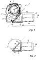
- Fig. 1 illustrates a burner 1.
- the burner 1 has a fan house 2 to which a motor 4 is attached.
- the motor 4 is adapted to drive a fan wheel 6, which is also shown in Fig. 4.
- the centre axis CA of the fan wheel 6 coincides with the centre axis of the motor 4.
- the fan wheel 6 is located in a first portion 8 of the fan house 2, which first portion 8 is the upper portion of the fan house 2 as seen in Fig. 1.
- the fan wheel 6 is adapted for producing a flow of a gas containing oxygen, normally this gas is air, which flow is to be forwarded to a second portion 10 of the fan house 2, which second portion 10 is the lower portion of the fan house 2 as seen in Fig. 1. In the second portion 10 a desired gas flow pattern is established.
- EP 1 022 470 B1 A preferred alternative of how such a gas flow pattern could appear is shown in EP 1 022 470 B1 .
- a fan house As is illustrated in Fig. 1 of EP 1 022 470 B1 a fan house is preferably provided with a surrounding wall of such a shape that a desired air pressure is achieved.
- a front part 12 is detachably mounted to the fan house 2.
- the front part 12 is adapted for forwarding the flow of gas from the fan house 2 to a cylindrical burner tube 14.
- the burner tube 14 is adapted for being mounted in a boiler, not shown. Inside the burner tube 14 the flow of gas is mixed with a fuel, such as oil or gas, resulting in the combustion of the fuel in the presence of the oxygen of the gas.
- the fan house 2 When performing maintenance work on the burner 1 the fan house 2 is detached from the front part 12 and the burner tube 14. It is normally preferred to leave the burner tube 14 and the front part 12 in place in the boiler while maintaining the fan house 2.
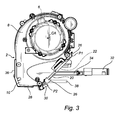
- Fig. 2 illustrates the burner tube 14 and the front part 12 after the fan house 2 has been detached there from.
- the front part 12 has a circumferential front part connecting surface 16 which surrounds a front part opening 18.
- the front part opening 18 is adapted for allowing the gas from the fan house 2 to enter the interior of the front part 12, which generally has the shape of an open cylinder, such that the gas can be forwarded through the front part 12 to the burner tube 14.
- the circumferential front part connecting surface 16 has an angle ⁇ of 135° to a centre line CB of the burner tube 14, which centre line CB substantially coincides also with the centre line of the cylindrical front part 12.
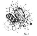
- Fig. 3 illustrates the fan house 2 after it has been detached from the front part 12.
- the fan house 2 has a circumferential fan house connecting surface 20 which surrounds a fan house opening 22.
- the circumferential fan house connecting surface 20, which is also shown in Fig. 4, is adapted for cooperating with said circumferential front part connecting surface 16 in such a manner that said front part connecting surface 16 lies close to said fan house connecting surface 20 to form a sealed connection, as it is illustrated in Fig. 1 of the present application.
- the circumferential front part connecting surface 16 is provided with interlocking portions 24 that are adapted for co-operating with corresponding interlocking portions 26 provided on the circumferential fan house connecting surface 20, which are illustrated in Fig. 3 and Fig. 4.
- Fig. 3 furthermore illustrates that the circumferential fan house connecting surface 20 is substantially parallel to the axis of rotation CA of the fan wheel 6.
- the fan house connecting surface 20 extends, as seen in Fig. 3, from a first point P1, which is located adjacent to the transition between the first portion 8 and the second portion 10 of the fan house 2, to a second point P2 which is located on a surface 28 of said second portion 10, which surface 28 is remote from said first portion 8.
- the surface 28 of the second portion 10 of the fan house 2 is opposite to the first portion 8.
- the fan house connecting surface 20 extends from the point P1 and in a direction away from the burner tube 14 towards the point P2. Consequently, a distance L1, parallel to the centre line CB of the burner tube 14, from a free terminal end 15 of the burner tube 14 to the point P1 will be shorter than a distance L2, parallel to the centre line CB, from the free terminal end 15 of the burner tube 14 to the point P2, as shown in Fig. 1 of the present application.
- a bolt 30 is rotatably mounted to the surface 28.
- the bolt 30 is adapted for urging the interlocking portions 24 of the circumferential front part connecting surface 16 into engagement with the interlocking portions 26 of the circumferential fan house connecting surface 20, thereby providing for a firm attachment, still detachable, between the fan house 2 and the front part 12.
- a fuel supply device comprises a fuel nozzle, such as an oil nozzle 32, and a fuel supply pipe 34, to which the oil nozzle 32 is fastened.
- the fuel supply pipe 34 is mounted on a back side 36 of the second portion 10 of the fan house 2.
- a photocell 38 which is adapted for supervision of a flame in the burner tube 14, is also mounted to the back side 36.
- Fig. 4 illustrates the fan house 2 after it has been detached from the front part 12.
- the fan house 2 has, as it is shown in Fig. 4, been turned around for the purpose of facilitating maintenance of a gas intake 40 attached to the fan house 2, and in particular for facilitating maintenance of the fan wheel 6, the fuel nozzle 32, the photocell 38 and the interior of the fan house 2.
- the fan house opening 22, which is encircled by the circumferential fan house connecting surface 20, has a generally elliptic shape, which makes it larger compared to a circular opening obtained in the prior art, as represented by US 6,488,496 .
- the large elliptic fan house opening 22 provides for easier access to the interior of the fan house 2, since it becomes easier to insert a human hand, and/or instruments through such a fan house opening 22. Furthermore, it is clear from Fig. 4 that the fan house opening 22 opens very much towards the fan wheel 6. This is thanks to the fact that the circumferential front part connecting surface 16 has an angle ⁇ of 135° to the centre line CB of the burner tube 14, the circumferential fan house connecting surface 20 having a complementary angle, such that the fan wheel 6 can be accessed almost from above, as shown in Fig. 4.
- the angle, ⁇ , between the circumferential front part connecting surface 16 and the centre line CB of the burner tube 14 is 135°.
- This angle can varied between certain limits.
- the angle ⁇ is not less than 125°.
- An angle ⁇ of less than 125° would not provide the desired good access to the fan wheel 6 and to the interior of the fan house 2.
- the angle ⁇ is not more than 145°.
- An angle ⁇ of more than 145° would mean that the second point P2 would be located very close to the back side 36 of the fan house 2. Such a location might deteriorate the desired flow pattern of the gas, since the flow pattern is, at such a point, still very sensitive to disturbances, which may be caused at the joint between the fan house 2 and the front part 12.
- the angle, ⁇ , between the circumferential front part connecting surface 16 and the centre line CB of the burner tube 14 is preferably in the range of 125° to 145°, more preferably in the range of 130° to 140°.
- the burner tube 14 and the front part 12 have a circular cross-section. It will be appreciated that other cross-sections are also possible.
- the burner tube and the front part could have a square, ellipsoidal, or hexagonal cross-section.
Landscapes
- Engineering & Computer Science (AREA)
- Chemical & Material Sciences (AREA)
- Combustion & Propulsion (AREA)
- Mechanical Engineering (AREA)
- General Engineering & Computer Science (AREA)
- Air Supply (AREA)
Priority Applications (1)
| Application Number | Priority Date | Filing Date | Title |
|---|---|---|---|
| EP06124537A EP1925882A1 (de) | 2006-11-22 | 2006-11-22 | Brenner |
Applications Claiming Priority (1)
| Application Number | Priority Date | Filing Date | Title |
|---|---|---|---|
| EP06124537A EP1925882A1 (de) | 2006-11-22 | 2006-11-22 | Brenner |
Publications (1)
| Publication Number | Publication Date |
|---|---|
| EP1925882A1 true EP1925882A1 (de) | 2008-05-28 |
Family
ID=37896151
Family Applications (1)
| Application Number | Title | Priority Date | Filing Date |
|---|---|---|---|
| EP06124537A Withdrawn EP1925882A1 (de) | 2006-11-22 | 2006-11-22 | Brenner |
Country Status (1)
| Country | Link |
|---|---|
| EP (1) | EP1925882A1 (de) |
Cited By (1)
| Publication number | Priority date | Publication date | Assignee | Title |
|---|---|---|---|---|
| EP2792950A1 (de) * | 2013-04-17 | 2014-10-22 | Guillot Industrie | Brenner mit Anschlusselement |
Citations (4)
| Publication number | Priority date | Publication date | Assignee | Title |
|---|---|---|---|---|
| NL299566A (de) * | ||||
| FR949132A (fr) * | 1947-06-27 | 1949-08-22 | Bruleurs Thermex Soc D | Perfectionnements aux brûleurs |
| DE1973489U (de) * | 1967-07-08 | 1967-11-30 | Landwehr & Schultz G M B H | Leichtoelbrenner. |
| EP1582809A2 (de) * | 2004-03-30 | 2005-10-05 | Compagnie Europeenne de Bruleurs S.A. | Gebläsebrenner mit einem bezüglich des Brennerkopfes geneigten Lüftungskasten |
-
2006
- 2006-11-22 EP EP06124537A patent/EP1925882A1/de not_active Withdrawn
Patent Citations (4)
| Publication number | Priority date | Publication date | Assignee | Title |
|---|---|---|---|---|
| NL299566A (de) * | ||||
| FR949132A (fr) * | 1947-06-27 | 1949-08-22 | Bruleurs Thermex Soc D | Perfectionnements aux brûleurs |
| DE1973489U (de) * | 1967-07-08 | 1967-11-30 | Landwehr & Schultz G M B H | Leichtoelbrenner. |
| EP1582809A2 (de) * | 2004-03-30 | 2005-10-05 | Compagnie Europeenne de Bruleurs S.A. | Gebläsebrenner mit einem bezüglich des Brennerkopfes geneigten Lüftungskasten |
Cited By (2)
| Publication number | Priority date | Publication date | Assignee | Title |
|---|---|---|---|---|
| EP2792950A1 (de) * | 2013-04-17 | 2014-10-22 | Guillot Industrie | Brenner mit Anschlusselement |
| FR3004789A1 (fr) * | 2013-04-17 | 2014-10-24 | Guillot Ind Sa | Bruleur avec organe de raccordement |
Similar Documents
| Publication | Publication Date | Title |
|---|---|---|
| JP2017083044A (ja) | 給湯器 | |
| EP1925882A1 (de) | Brenner | |
| EP1930661A2 (de) | Zusammenklappbarer Campingkocher | |
| CN204513415U (zh) | 一种封闭式沼气火炬 | |
| JP2016109352A (ja) | ボイラ装置 | |
| CN112377901A (zh) | 一种冷凝锅炉的空气燃气预混燃烧器的燃烧头及其预混燃烧方法 | |
| CN201289081Y (zh) | 改进中心火盖的灶具燃烧器 | |
| CN101082424B (zh) | 燃气灶具 | |
| US20090032013A1 (en) | Preformed fireplace capable of venting vertically or horizontally | |
| CN206268004U (zh) | 一种通用汽油机点火器 | |
| CN218635149U (zh) | 蒸汽式喷雾器的燃烧机构和蒸汽式喷雾器 | |
| JP2017198378A (ja) | ボイラ | |
| CN117759956B (zh) | 超薄燃气灶 | |
| CN219571917U (zh) | 一种燃气燃烧器 | |
| KR20130125427A (ko) | 보일러용 급배기관의 연통 접속구조 | |
| JP4937416B1 (ja) | カセットボンベ用コンロ | |
| CN115681965B (zh) | 燃烧器以及燃气灶 | |
| CN102042481B (zh) | 一种瓶装液化石油气全自动强制气化机 | |
| CN109114554B (zh) | 一种燃烧室、燃烧器与燃气灶 | |
| JP7575671B2 (ja) | 燃焼装置及び温水装置 | |
| CN211781995U (zh) | 燃气热水器 | |
| JP7135834B2 (ja) | 炭酸ガス供給装置 | |
| CN202955692U (zh) | 一种醇基燃料气化燃烧炉头 | |
| KR20000019302A (ko) | 보일러 | |
| JP7151502B2 (ja) | 炭酸ガス供給装置 |
Legal Events
| Date | Code | Title | Description |
|---|---|---|---|
| PUAI | Public reference made under article 153(3) epc to a published international application that has entered the european phase |
Free format text: ORIGINAL CODE: 0009012 |
|
| AK | Designated contracting states |
Kind code of ref document: A1 Designated state(s): AT BE BG CH CY CZ DE DK EE ES FI FR GB GR HU IE IS IT LI LT LU LV MC NL PL PT RO SE SI SK TR |
|
| AX | Request for extension of the european patent |
Extension state: AL BA HR MK RS |
|
| AKX | Designation fees paid | ||
| REG | Reference to a national code |
Ref country code: DE Ref legal event code: 8566 |
|
| STAA | Information on the status of an ep patent application or granted ep patent |
Free format text: STATUS: THE APPLICATION IS DEEMED TO BE WITHDRAWN |
|
| 18D | Application deemed to be withdrawn |
Effective date: 20081129 |