EP1925755B1 - Mécanisme de centrage à deux ètapes de soupape à tiroir pour engin de travaux - Google Patents
Mécanisme de centrage à deux ètapes de soupape à tiroir pour engin de travaux Download PDFInfo
- Publication number
- EP1925755B1 EP1925755B1 EP20070120897 EP07120897A EP1925755B1 EP 1925755 B1 EP1925755 B1 EP 1925755B1 EP 20070120897 EP20070120897 EP 20070120897 EP 07120897 A EP07120897 A EP 07120897A EP 1925755 B1 EP1925755 B1 EP 1925755B1
- Authority
- EP
- European Patent Office
- Prior art keywords
- spool
- spring
- stroke
- biasing
- biasing member
- Prior art date
- Legal status (The legal status is an assumption and is not a legal conclusion. Google has not performed a legal analysis and makes no representation as to the accuracy of the status listed.)
- Not-in-force
Links
Images


Classifications
-
- E—FIXED CONSTRUCTIONS
- E02—HYDRAULIC ENGINEERING; FOUNDATIONS; SOIL SHIFTING
- E02F—DREDGING; SOIL-SHIFTING
- E02F9/00—Component parts of dredgers or soil-shifting machines, not restricted to one of the kinds covered by groups E02F3/00 - E02F7/00
- E02F9/20—Drives; Control devices
- E02F9/22—Hydraulic or pneumatic drives
- E02F9/2264—Arrangements or adaptations of elements for hydraulic drives
- E02F9/2267—Valves or distributors
-
- E—FIXED CONSTRUCTIONS
- E02—HYDRAULIC ENGINEERING; FOUNDATIONS; SOIL SHIFTING
- E02F—DREDGING; SOIL-SHIFTING
- E02F3/00—Dredgers; Soil-shifting machines
- E02F3/04—Dredgers; Soil-shifting machines mechanically-driven
- E02F3/28—Dredgers; Soil-shifting machines mechanically-driven with digging tools mounted on a dipper- or bucket-arm, i.e. there is either one arm or a pair of arms, e.g. dippers, buckets
- E02F3/34—Dredgers; Soil-shifting machines mechanically-driven with digging tools mounted on a dipper- or bucket-arm, i.e. there is either one arm or a pair of arms, e.g. dippers, buckets with bucket-arms, i.e. a pair of arms, e.g. manufacturing processes, form, geometry, material of bucket-arms directly pivoted on the frames of tractors or self-propelled machines
- E02F3/3414—Dredgers; Soil-shifting machines mechanically-driven with digging tools mounted on a dipper- or bucket-arm, i.e. there is either one arm or a pair of arms, e.g. dippers, buckets with bucket-arms, i.e. a pair of arms, e.g. manufacturing processes, form, geometry, material of bucket-arms directly pivoted on the frames of tractors or self-propelled machines the arms being pivoted at the rear of the vehicle chassis, e.g. skid steer loader
-
- F—MECHANICAL ENGINEERING; LIGHTING; HEATING; WEAPONS; BLASTING
- F15—FLUID-PRESSURE ACTUATORS; HYDRAULICS OR PNEUMATICS IN GENERAL
- F15B—SYSTEMS ACTING BY MEANS OF FLUIDS IN GENERAL; FLUID-PRESSURE ACTUATORS, e.g. SERVOMOTORS; DETAILS OF FLUID-PRESSURE SYSTEMS, NOT OTHERWISE PROVIDED FOR
- F15B13/00—Details of servomotor systems ; Valves for servomotor systems
- F15B13/02—Fluid distribution or supply devices characterised by their adaptation to the control of servomotors
- F15B13/04—Fluid distribution or supply devices characterised by their adaptation to the control of servomotors for use with a single servomotor
- F15B13/0401—Valve members; Fluid interconnections therefor
- F15B13/0402—Valve members; Fluid interconnections therefor for linearly sliding valves, e.g. spool valves
-
- F—MECHANICAL ENGINEERING; LIGHTING; HEATING; WEAPONS; BLASTING
- F16—ENGINEERING ELEMENTS AND UNITS; GENERAL MEASURES FOR PRODUCING AND MAINTAINING EFFECTIVE FUNCTIONING OF MACHINES OR INSTALLATIONS; THERMAL INSULATION IN GENERAL
- F16K—VALVES; TAPS; COCKS; ACTUATING-FLOATS; DEVICES FOR VENTING OR AERATING
- F16K11/00—Multiple-way valves, e.g. mixing valves; Pipe fittings incorporating such valves
- F16K11/02—Multiple-way valves, e.g. mixing valves; Pipe fittings incorporating such valves with all movable sealing faces moving as one unit
- F16K11/06—Multiple-way valves, e.g. mixing valves; Pipe fittings incorporating such valves with all movable sealing faces moving as one unit comprising only sliding valves, i.e. sliding closure elements
- F16K11/065—Multiple-way valves, e.g. mixing valves; Pipe fittings incorporating such valves with all movable sealing faces moving as one unit comprising only sliding valves, i.e. sliding closure elements with linearly sliding closure members
- F16K11/07—Multiple-way valves, e.g. mixing valves; Pipe fittings incorporating such valves with all movable sealing faces moving as one unit comprising only sliding valves, i.e. sliding closure elements with linearly sliding closure members with cylindrical slides
-
- Y—GENERAL TAGGING OF NEW TECHNOLOGICAL DEVELOPMENTS; GENERAL TAGGING OF CROSS-SECTIONAL TECHNOLOGIES SPANNING OVER SEVERAL SECTIONS OF THE IPC; TECHNICAL SUBJECTS COVERED BY FORMER USPC CROSS-REFERENCE ART COLLECTIONS [XRACs] AND DIGESTS
- Y10—TECHNICAL SUBJECTS COVERED BY FORMER USPC
- Y10T—TECHNICAL SUBJECTS COVERED BY FORMER US CLASSIFICATION
- Y10T137/00—Fluid handling
- Y10T137/7722—Line condition change responsive valves
- Y10T137/7837—Direct response valves [i.e., check valve type]
- Y10T137/7904—Reciprocating valves
- Y10T137/7905—Plural biasing means
Definitions
- the present invention relates to a two stage spool centering mechanism.
- US Patent 4479514 discloses a float positioning assembly for servo actuated proportional control valves which increases the percentage of available pilot pressure for use during normal "raise” and “lower” modes of operation.
- the invention provides a valve arrangement comprising: a spool movable from a center position in a first direction through a first stroke and in a second direction through a second stroke; a first biasing member having a first spring constant and a first preload; and a second biasing member having a second spring constant lower than the first spring constant and a second preload higher than the first preload.
- the first biasing member and not the second biasing member biases the spool toward the center position through the entire first stroke.
- the first biasing member and not the second biasing member biases the spool toward the center position during movement of the spool from the center position to an intermediate position within the second stroke.
- the first and second biasing members act in series to bias the spool toward the center position during movement of the spool from the intermediate opposition to an end of the second stroke, then biasing force of the first and second biasing members acting in series being less than the first spring constant and less than the second spring constant.
- the valve arrangement comprises a force transferring member having first and second sides against which the respective first and second biasing members bear.
- the invention may be used, for example, in a skid steer loader.
- the first stroke may correspond to a raising stroke of a lift spool in the main control valve of the loader
- the second stroke may correspond to a lowering stroke.
- the lift spool is resisted by the relatively high first spring constant and may enable a metering mode of operation that facilitates relatively precise control of the lift arm.
- the spool moves into the second portion of the lowering stroke, the lift arm and bucket of the skid steer loader are acted upon only by the forces of gravity.
- the spool is resisted by the relatively low spring constant of the first and second biasing members acting in series when the spool is in the second portion of the lowering stroke.
- the relatively low spring constant permits the lift spool to be moved into and held within the second portion of the lowering stroke with minimal use of hydraulic pressure and vehicle power so that available hydraulic pressure and vehicle power may be used for other purposes.
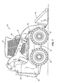
- Fig. 1 is a side view of a skid steer loader according to one embodiment of the present invention.
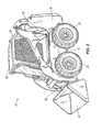
- Fig. 2 is a perspective view of the skid steer loader.
- Fig. 3 is a cross sectional view of the main control valve of the skid steer loader.
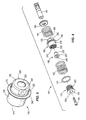
- Fig. 4 is an exploded view of a first embodiment of a two-stage valve assembly.
- Fig. 5 is a perspective view of an intermediate member of the two-stage valve assembly.
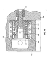
- Fig. 6 is a cross-sectional view of the two-stage valve arrangement of Fig. 4 during a raising stroke.
- Fig. 7 is a cross-sectional view of the two-stage valve arrangement of Fig. 4 at an intermediate position of a lowering stroke.
- Fig. 8 is a cross-sectional view of the two-stage valve arrangement of Fig. 4 at the end of the lowering stroke.
- Fig. 9 is an exploded view of another embodiment of the two-stage valve assembly.
- Fig. 10 is a cross-sectional view of the two-stage valve arrangement of Fig. 9 during a raising stroke.
- Fig. 11 is a cross-sectional view of the two-stage valve arrangement of Fig. 9 at an intermediate position of a lowering stroke.
- Fig. 12 is a cross-sectional view of the two-stage valve arrangement of Fig. 9 at the end of the lowering stroke.
- Figs. 1 and 2 depict a skid steer loader 10 having a frame 15 supported by two right side wheels 20 and two left side wheels 25, an internal combustion engine 30, an operator compartment 35 that contains an operator control 37, right and left lift arms 40, and a bucket 45 mounted for tilting between the distal ends of the lift arms 40.
- the invention is illustrated embodied in a skid steer loader 10, the invention may be embodied in other vehicles and machines.
- the illustrated operator control 37 takes the form of a joystick, in other embodiments, the control may include multiple joysticks and/or foot pedals.
- the right side wheels 20 are driven independently of the left side wheels 25.
- the loader 10 moves forward and backward, depending on the direction of rotation of the wheels 20, 25.
- the loader 10 turns by rotating the right and left side wheels 20, 25 in the same direction but at different rates, and rotates about a substantially zero turn radius by rotating the right and left side wheels 20, 25 in opposite directions.
- the lift arms 40 raise (i.e., rotate counterclockwise in Fig. 1 ) and lower (i.e., rotate clockwise in Fig. 1 ) with respect to the frame 15 under the influence of lift cylinders 50 mounted between the frame 15 and the lift arms 40.
- the bucket 45 tilts with respect to the arms 40 to curl (i.e., rotate counterclockwise in Fig. 1 ) and dump (i.e., rotate clockwise in Fig. 1 ) under the influence of tilt cylinders 55 mounted between the lift arms 40 and the bucket 45.
- Various auxiliary implements or devices may be substituted for or used in conjunction with the bucket 45.
- auxiliary implements includes augers, jack hammers, trenchers, grapples, rotary sweepers, stump grinders, saws, concrete mixers, pumps, chippers, snow throwers, rotary cutters, and backhoes.
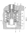
- Fig. 3 illustrates a portion of a main control valve (“MCV") 100 of the skid steer loader 10.
- the MCV 100 includes a spool housing 105, a spring housing 110, an actuator housing 115, a lift spool 120, a tilt spool 125, and an auxiliary spool 130.
- the spool housing 105 includes an inlet 131, an outlet 132, and a plurality of conduits 133.
- a pressure relief conduit 134 permits hydraulic fluid to bleed away from the MCV 100 if pressure exceeds a selected threshold.
- the lift, tilt, and auxiliary spools 120, 125, 130 are illustrated in Fig. 3 in center or neutral positions. When in the neutral positions, the lift and tilt spools do not permit the lift and tilt cylinders 50, 55 to extend or retract, and therefore maintain the lift arms 40 and bucket 45 in fixed positions.
- the lift, tilt, and auxiliary spools are shifted under the influence of the operator control 37 off center to allow hydraulic fluid to flow through the conduits 133 to the respective lift cylinders 50, tilt cylinders 55, and auxiliary implement.
- the tilt and auxiliary spools 125, 130 are centered within the MCV 100 with springs 135 that bear against caps 137, and the lift spool 120 is centered with a two-stage spring assembly 140.
- the springs 135, caps 137, and the two-stage spring assembly 140 are in cavities 143 in the spring housing 110. Hydraulic actuators within the spring housing 110 and/or the actuator housing 115 engage the ends of the lift, tilt, and auxiliary spools 120, 125, 130 and shift them left and right.
- the two-stage spring assembly 140 includes first and second springs 145, 150, an intermediate member 160, inner and outer end washers 165, 170, a threaded cap 175, a fastener 180, and a spacer 185.
- the first and second springs 145, 150 are arranged in series relation to each other, and have different spring constants, with the spring constant of the first spring 145 being higher than that of the second spring 150.
- the intermediate member 160 includes a flange 190. Between the flange 190 and a first end 193 of the intermediate member 160 is a first cylindrical portion 195 having diametrically-opposed flats 200 on its outer surface and diametrically-opposed holes 203 (also seen in Figs. 3 and 6-8 ) communicating through the intermediate member wall.
- the holes 203 provide a flow path that permits oil to freely flow into and out of the intermediate member to accommodate oil displaced by movement of the intermediate member 160 in its cavity 143.
- the caps 137 ( Fig. 3 ) on the centering springs 135 of the tilt and auxiliary spools 125, 130 also include oil bypass holes 203 to facilitate movement of the caps 137 in their cavities 143.
- the first end 193 of the intermediate member 160 is closed except for a hole 205.
- a second cylindrical portion 215 having a smooth outer surface and female threads 220 ( Fig. 4 ).
- the threaded cap 175 includes male threads 223 and a flared end 225 with a socket-shaped hole 230 in it.
- the spacer 185 includes an elongated portion 235, a lip 240, and a longitudinal bore 245.
- the two-stage spring assembly 140 is assembled by first positioning the spacer 185 within the intermediate member 160 such that the elongated portion 235 of the spacer 185 extends out of the hole 205 in the first end 193 of the intermediate member 160.
- the lip 240 of the spacer 185 is larger than the hole 205, so the spacer 185 cannot pass entirely through the hole 205.
- Tightening the cap 175 into the second cylindrical portion 215 may be facilitated by inserting a hex wrench, such as an Allen wrench, into the socket-shaped hole 230, and by fitting a wrench against the flats 200 on the first cylinder portion 195 of the intermediate member 160. Relative rotation of the wrenches will result in tightening or loosening of the cap 175 in the intermediate member 160.
- a hex wrench such as an Allen wrench
- the second spring 150 and outer washer 170 are trapped between the flange 190 of the intermediate member 160 and the flared end 225 of the threaded cap 175.
- the length of the second cylindrical portion 215 is shorter than the at-rest length of the second spring 150.
- the space between the outer washer 170 and flange 190 corresponds to a desired compressive preload on the second spring 150 when the threaded cap 175 is snugly threaded into the second cylindrical portion 215.
- the fastener 180 is inserted through the socket-shaped hole 230 in the threaded cap 175, extended through the longitudinal bore 245 in the spacer 185, and threaded into the end of the lift spool 120.
- the socket-shaped hole 230 provides access for a tool, such as an Allen wrench, to engage and tighten the fastener 180 into the end of the lift spool 120.
- a tool such as an Allen wrench
- the space between the flange 190 and the inner washer 165 therefore decreases, which results in a compressive preload on the first spring 145.
- the fastener 180 is advanced into the end of the lift spool 120 until the spacer 185 is tightly sandwiched between the fastener 180 and the end of the lift spool 120.
- the length of the spacer 185 corresponds to a desired deflection or preload on the first spring 145.
- hydraulic fluid is permitted to flow to a "lower” side of the lift cylinders 50, which retracts the lift cylinders 50 and causes the lift arms 40 to lower.
- the total displacements of the lift spool 120 from the center position to the right and left are referred to as the "raising stroke” and "lowering stroke,” respectively.
- the lip 240 of the spacer 185 abuts against the inner side of the first end 193 of the intermediate member 160 and pulls the intermediate member 160 to the right.
- the intermediate member 160 acts as a force transferring member as it transfers the force of rightward movement of the spool 120 and spacer 185 into compression of the first spring 145 through the flange 190.
- the distance between the flange 190 and the inner washer 165 becomes smaller and the first spring 145 deflects (i.e., is compressed).
- the outer washer 170 is lifted from the step 250 in the spring housing 110, but the space between the outer washer 170 and the flange 190 remains constant (i.e., no deflection of the second spring 150 beyond its preloaded state).
- the intermediate member 160 insulates the second spring 150 from exposure to any forces in the first spring 145, and the lift spool 120 is resisted only by the spring constant of the first spring 145 during the entire raising stroke.
- the lowering stroke of the lift spool 120 has two portions.
- the first portion of the lowering stroke is movement of the lift spool 120 from the center position ( Fig. 3 ) to an intermediate position ( Fig. 7 ).
- the second portion of the lowering stroke is movement of the lift spool 120 from the intermediate position to the end of the lowering stroke ( Fig. 8 ).
- the intermediate member 160 acts as a force transferring member because it transfers biasing forces from the first spring 145 into the second spring 150.
- the intermediate member 160 is in the force path (i.e., transfers forces from the lift spool 120 to the first spring 145) in both the raising and lowering strokes.
- the inner washer 165 moves away from the spool housing 105 of the MCV 100, and the spacer 185 slides within the hole 205 in the intermediate member 160. The spacer 185 therefore only transfers forces from the spool 120 to the first spring 145 during the raising stroke, and is out of the force path in the lowering stroke. As the inner washer 165 moves closer to the flange 190, the compressive load in the first spring 145 increases.
- the intermediate position illustrated in Fig. 7 is the point at which the load on the first spring 145 equals the pre-load on the second spring 150.
- the first and second springs 145, 150 are both deflected.
- the combined spring constant is therefore lower than both of the first and second spring constants.
- the spring housing 110 may be constructed such that the threaded cap 175 bottoms out or is close to bottoming out against the spring housing 110 at the end of the lowering stroke, as illustrated in Fig. 8 .
- Figs. 9-12 illustrate another embodiment 300 of the two-stage spring assembly, in which the first and second springs 145, 150 act in series but are nested instead of end-to-end.
- the spring assembly 300 of this embodiment includes inner and outer washers 310, 315, an intermediate member 320 having a flange 325, a fastener 330, and a spacer 335 having a lip 340.
- the fastener 330 extends through the spacer 335 and is threaded into the end of the lift spool 120 with one end of the spacer 335 abutting the end of the lift spool 120.
- the first spring 145 is captured between the inner washer 310, which abuts against the spool housing 105 and the outer washer 315, which abuts against the lip 340 of the spacer 335.
- the spacer 335 is sized such that a desired preload is applied to the first spring 145 when the fastener 330 is threaded tightly into the end of the lift spool 120.
- the intermediate member 320 has a body that defines an inner space in which the first spring 145 is received, and the flange end 325 of the intermediate member 320 abuts against the spool housing 105.
- the opposite end of the intermediate member 320 includes a radially-protruding rim 345 against which the outer washer 315 abuts.
- the rim 345 surrounds the lip 340 of the spacer 335 such that the spacer can axially move through the hole defined by the rim 345.
- the hole in the outer washer 315 is too small for the lip 340 to fit through.
- the second spring 150 surrounds the outside of the intermediate member 320 and is trapped between the flange 325 and the step 250 in the spring housing 110.
- the intermediate member 320 acts as a force transferring member because it transfers biasing forces from the first spring 145 into the second spring 150 through the body of the intermediate member 320 and the flange 325. Because the preload on the first spring 145 is lower than the preload on the second spring 150, only the first spring 145 deflects. The inner washer 310 moves away from the spool housing 105, and the spacer 335 slides through the hole defined by the rim 345 in the intermediate member 320.
- the spacer 335 therefore only transfers forces from the spool 120 to the first spring 145 during the raising stroke, and is out of the force path in the lowering stroke.
- the intermediate position illustrated in Fig. 11 is the point at which the load on the first spring 145 equals the pre-load on the second spring 150.
- the first and second springs 145, 150 are both deflected.
- the springs 145, 150 act in series, and the combined spring constant is calculated with the equation recited above.
- the combined spring constant is lower than both of the first and second spring constants.
- both springs 145, 150 deflect, both the spacer 335 and the intermediate member 320 move left.
- the space between the flange 325 and the step 250 in the spring housing 110 decreases and load is applied to the second spring 150.
- the spring housing 110 may be constructed such that the spacer 335 bottoms out or is close to bottoming out against the spring housing 110 at the end of the lowering stroke, as illustrated in Fig. 12 .
- the lift spool 120 is said to be in "metering mode" when its movement is resisted by the first spring 145 alone (i.e., during the entire raising stroke and during the first portion of the lowering stroke).
- the higher spring constant of the first spring 145 requires the hydraulic actuators in the spring housing 110 and/or the actuator housing 115 to apply a relatively high level of force per unit deflection of the lift spool 120 in metering mode.
- the relatively high force-to-deflection ratio in metering mode permits the position of the lift spool 120 to be finely adjusted, which facilitates relatively fine adjustment of the lift arms 40.
- the intermediate position ( Figs. 7 and 11 ) is the end of the metering mode portion of the lowering stroke.
- the lift spool 120 When the lift spool 120 has moved past the intermediate position (i.e., is between Figs. 7 and 8 or between Figs. 11 and 12 ), it is said to be in "float mode," in which the lift arms 40 and bucket 45 of the skid steer loader 10 are not actively lowered or raised by the hydraulic system, and are acted upon only by gravity. Resistance to lift spool 120 deflection drops from the first spring constant to the combined spring constant as the lift spool moves past the intermediate position. The lower spring constant created by the springs 145, 150 being deflected in series permits the hydraulic actuators in the spring housing 110 and/or the actuator housing 115 to apply a relatively low level of force per unit deflection of the lift spool 120 in float mode.
- the relatively low force-to-deflection ratio in float mode permits the lift spool 120 to be moved into and maintained within the float mode with minimal use of hydraulic pressure in the hydraulic circuit, and with minimal use of vehicle power. Available vehicle power and hydraulic pressure are therefore maximized for use in non-lifting operations while the lift spool 120 is in float mode.
- Float mode is used by operators to back-drag, back-smooth or back-scrape terrain.
- the pitch of the bucket 45 determines the aggressiveness of the scraping or smoothing; the bucket 45 will glide more easily over (i.e., not scrape as aggressively) the terrain when the smooth undersurface of the bucket 45 is in contact with the terrain rather than the sharper edge of the bucket 45.
- the bucket 45 may be tilted such that the smooth bottom surface of the bucket 45 is facing down, then the lift spool 120 may be put into float mode, and then the skid steer loader 10 is moved in reverse over the terrain such that the back of the bucket 45 glides over the terrain to smooth it.
- the bucket 45 may be tilted so that the relatively sharp edge of the bucket 45 contacts the terrain, then the lift spool 120 may be put into float mode and the skid steer loader 10 backed up over the terrain. In any event, the bucket 45 and lift arms 40 will ride up and down over the terrain and only scrape and smooth to the extent that the influence of gravity permits.
- a relatively hard terrain e.g., compacted earth, gravel
- the lift spool 120 may be put into float mode and the skid steer loader 10 backed up over the terrain.
- the bucket 45 and lift arms 40 will ride up and down over the terrain and only scrape and smooth to the extent that the influence of gravity permits.
- the first spring constant is 167 lbs/in
- the second spring constant is 89 lbs/in
- the preload on the first spring 145 is 10 lbs
- the preload on the second spring 150 is 60 lbs.
- the resistance to lift spool 120 movement in metering mode is 167 lbs/in
- the resistance to lift spool 120 movement in float mode is about 58 lbs/in.
- the first spring 145 is deflected about 0.06 inches to achieve the 10 lbs. preload.
- the distance between the center and intermediate positions in the lowering stroke i.e., the deflection of the first spring to achieve a total load of 60 lbs) is about 0.30 inches.
- first and second compression springs 145, 150 can be replaced with other biasing members, such as elastomeric materials, tension springs, or substantially any other members with shape memory that will apply biasing forces to the lift spool 120.
- biasing members such as elastomeric materials, tension springs, or substantially any other members with shape memory that will apply biasing forces to the lift spool 120.
- the term "spring constant" used above is intended to include the ratio of load to deflection, even if not linear, characterizing any suitable biasing members in addition to the first and second springs 145, 150.
- first spring 145 and second spring 150 can be replaced with multiple springs acting in parallel or series to achieve the desired spring constants and preloads.
- first spring and second spring should not be construed as limited to the single first and second springs 145, 150 in the illustrated embodiments.
Landscapes
- Engineering & Computer Science (AREA)
- General Engineering & Computer Science (AREA)
- Mechanical Engineering (AREA)
- Mining & Mineral Resources (AREA)
- Civil Engineering (AREA)
- Structural Engineering (AREA)
- Physics & Mathematics (AREA)
- Fluid Mechanics (AREA)
- Servomotors (AREA)
- Power Steering Mechanism (AREA)
- Multiple-Way Valves (AREA)
- Springs (AREA)
Claims (6)
- Agencement de soupape comprenant :un tiroir cylindrique (120) déplaçable depuis une position centrale dans une première direction sur une première course et dans une deuxième direction sur une deuxième course ; etun premier organe de précontrainte (145) ayant une première constante de ressort et une première force de précontrainte ; etun deuxième organe de précontrainte (150) ayant une deuxième constante de ressort inférieure à la première constante de ressort et une deuxième force de précontrainte supérieure à la première force de précontrainte ;le premier organe de précontrainte, et pas le deuxième organe de précontrainte, sollicitant le tiroir cylindrique vers la position centrale sur toute la première course et au cours du mouvement du tiroir cylindrique depuis la position centrale jusqu'à une position intermédiaire dans la deuxième course ; etles premier et deuxième organes de précontrainte agissant en série de manière à solliciter le tiroir cylindrique vers la position centrale au cours du mouvement du tiroir cylindrique depuis la position intermédiaire jusqu'à une extrémité de la deuxième course, la force de précontrainte du premier et du deuxième organe de précontrainte agissant en série étant inférieure à la première constante de ressort et inférieure à la deuxième constante de ressort, caractérisé en ce que l'agencement de soupape comprend en outre un organe de transfert de force (160) comprenant une bride (190) ayant des premier et deuxième côtés contre lesquels pressent les premier et deuxième organes de précontrainte respectifs, laquelle bride est interposée en fonctionnement entre les premier et deuxième organes de précontrainte de manière à transférer les forces de précontrainte depuis le premier organe de précontrainte jusqu'au deuxième organe de précontrainte au cours de la deuxième course.
- Agencement de soupape selon la revendication 1, comprenant en outre un moyen pour isoler le deuxième organe de précontrainte des forces de précontrainte du premier organe de précontrainte au cours de la première course, et un moyen pour transférer des forces de précontrainte depuis le premier organe de précontrainte jusqu'au deuxième organe de précontrainte au cours de la deuxième course.
- Agencement de soupape selon la revendication 1, dans lequel l'organe de transfert de force comporte des première (195) et deuxième (215) portions s'étendant à l'écart des premier et deuxième côtés respectifs de la bride ; les premier et deuxième organes de précontrainte entourant les première et deuxième portions respectives de l'organe de transfert de force.
- Agencement de soupape selon la revendication 1, comprenant en ou t r e un e attache (180) interconnectée au tiroir cylindrique pour appliquer une force de compression contre le premier organe de précontrainte, et un élément d'espacement (185) entre l'attache et le tiroir cylindrique, permettant d'obtenir une force de précontrainte souhaitée sur le premier organe de précontrainte en coinçant étroitement l'élément d'espacement entre l'attache et le tiroir cylindrique.
- Agencement de soupape selon la revendication 4, dans lequel l'élément d'espacement se déplace avec le tiroir cylindrique au cours des première et deuxième courses, et dans lequel l'agencement de soupape comprend en outre un organe de transfert de force qui transfère la force depuis l'élément d'espacement jusqu'au premier organe de précontrainte au cours de la première course mais pas au cours de la deuxième course.
- Agencement de soupape selon la revendication 1, dans lequel les premier et deuxième organes de précontrainte sont agencés bout à bout.
Applications Claiming Priority (1)
| Application Number | Priority Date | Filing Date | Title |
|---|---|---|---|
| US11/561,961 US7631591B2 (en) | 2006-11-21 | 2006-11-21 | Two stage spool centering mechanism |
Publications (3)
| Publication Number | Publication Date |
|---|---|
| EP1925755A2 EP1925755A2 (fr) | 2008-05-28 |
| EP1925755A3 EP1925755A3 (fr) | 2011-12-28 |
| EP1925755B1 true EP1925755B1 (fr) | 2013-02-20 |
Family
ID=39169450
Family Applications (1)
| Application Number | Title | Priority Date | Filing Date |
|---|---|---|---|
| EP20070120897 Not-in-force EP1925755B1 (fr) | 2006-11-21 | 2007-11-16 | Mécanisme de centrage à deux ètapes de soupape à tiroir pour engin de travaux |
Country Status (5)
| Country | Link |
|---|---|
| US (1) | US7631591B2 (fr) |
| EP (1) | EP1925755B1 (fr) |
| CN (1) | CN101196199B (fr) |
| CA (1) | CA2610546C (fr) |
| ES (1) | ES2406717T3 (fr) |
Families Citing this family (18)
| Publication number | Priority date | Publication date | Assignee | Title |
|---|---|---|---|---|
| DE102008008092A1 (de) * | 2007-11-28 | 2009-06-04 | Robert Bosch Gmbh | Ventilanordnung |
| RU2470120C1 (ru) * | 2011-07-08 | 2012-12-20 | Федеральное государственное бюджетное образовательное учреждение высшего профессионального образования "Сибирская государственная автомобильно-дорожная академия" (СибАДИ") | Гидромеханическая система стабилизации положения рабочего органа дорожно-строительной машины |
| US8858151B2 (en) * | 2011-08-16 | 2014-10-14 | Caterpillar Inc. | Machine having hydraulically actuated implement system with down force control, and method |
| JP6305162B2 (ja) * | 2014-03-31 | 2018-04-04 | Kyb株式会社 | 弁装置 |
| US9888785B2 (en) | 2014-04-21 | 2018-02-13 | Casper Sleep Inc. | Mattress |
| JP6717541B2 (ja) | 2016-07-28 | 2020-07-01 | キャタピラー エス エー アール エル | 弁装置およびこれを備えた流体圧システム |
| EP3418587B1 (fr) | 2017-06-22 | 2020-10-07 | Claverham Limited | Soupape hydraulique |
| US11116326B2 (en) | 2017-08-14 | 2021-09-14 | Casper Sleep Inc. | Mattress containing ergonomic and firmness-regulating endoskeleton |
| US10344858B2 (en) * | 2017-10-20 | 2019-07-09 | Ford Global Technologies, Llc | Transmission park control system |
| KR20200112869A (ko) * | 2018-01-08 | 2020-10-05 | 캐스퍼 슬립 인크. | 대화식 휴대용 조명 시스템 |
| WO2019209733A1 (fr) | 2018-04-23 | 2019-10-31 | Casper Sleep Inc. | Matelas de régulation de température |
| USD885640S1 (en) | 2018-10-23 | 2020-05-26 | Casper Sleep Inc. | Lamp assembly |
| JP2020122495A (ja) * | 2019-01-29 | 2020-08-13 | ナブテスコ株式会社 | 制御弁および方向切換弁 |
| USD908398S1 (en) | 2019-08-27 | 2021-01-26 | Casper Sleep Inc. | Mattress |
| USD921531S1 (en) | 2019-09-10 | 2021-06-08 | Casper Sleep Inc. | Zipper |
| USD927889S1 (en) | 2019-10-16 | 2021-08-17 | Casper Sleep Inc. | Mattress layer |
| US11460053B2 (en) | 2020-03-16 | 2022-10-04 | Parker-Hannifin Corporation | Open center control valve configured to combine fluid flow received from multiple sources |
| CN115978234B (zh) * | 2023-01-05 | 2023-07-14 | 宁波克泰液压有限公司 | 一种节流型三位五通电磁阀 |
Family Cites Families (14)
| Publication number | Priority date | Publication date | Assignee | Title |
|---|---|---|---|---|
| US2778314A (en) * | 1954-02-24 | 1957-01-22 | New York Air Brake Co | Sharp response spring loaded pressure motor for controlling regulated devices |
| US3243025A (en) | 1964-03-12 | 1966-03-29 | Minneapolis Moline Inc | Control valve for hydraulically actuated clutches |
| US3386471A (en) | 1965-09-13 | 1968-06-04 | Clark Equipment Co | Flow control and cushioning valve |
| FR1472167A (fr) * | 1966-01-13 | 1967-03-10 | Renault | Perfectionnements aux distributeurs hydrauliques pour matériels agricoles |
| US3473566A (en) | 1968-04-19 | 1969-10-21 | Clark Equipment Co | Control valve |
| US3635365A (en) * | 1969-02-20 | 1972-01-18 | Clark Equipment Co | Tractor vehicle with hydrostatic drive means |
| US3935792A (en) | 1973-02-26 | 1976-02-03 | Caterpillar Tractor Co. | Pilot pump bleed control for earthmoving scrapers |
| US3895703A (en) | 1973-10-26 | 1975-07-22 | Caterpillar Tractor Co | Combined steering clutch and brake control for crawler tractors |
| JPS5824805B2 (ja) | 1974-10-11 | 1983-05-24 | 株式会社小松製作所 | セイギヨベン |
| US4013381A (en) | 1976-02-09 | 1977-03-22 | Caterpillar Tractor Co. | Pump control assembly having adjustable biasing means |
| JPS6327456Y2 (fr) * | 1981-04-18 | 1988-07-25 | ||
| DE3844412A1 (de) * | 1988-12-30 | 1990-07-05 | Rexroth Mannesmann Gmbh | Einseitig angesteuertes proportionalventil mit sicherheitseinrichtung |
| JP2784836B2 (ja) | 1990-05-11 | 1998-08-06 | 株式会社ゼクセル | 電磁切換弁 |
| FR2754000B1 (fr) * | 1996-09-30 | 1999-01-29 | Mailleux Sa | Dispositif de commande hydraulique du verin de levage d'un bras de chargeur agricole |
-
2006
- 2006-11-21 US US11/561,961 patent/US7631591B2/en active Active
-
2007
- 2007-11-14 CA CA2610546A patent/CA2610546C/fr active Active
- 2007-11-16 EP EP20070120897 patent/EP1925755B1/fr not_active Not-in-force
- 2007-11-16 ES ES07120897T patent/ES2406717T3/es active Active
- 2007-11-21 CN CN2007101939093A patent/CN101196199B/zh not_active Expired - Fee Related
Also Published As
| Publication number | Publication date |
|---|---|
| US7631591B2 (en) | 2009-12-15 |
| CA2610546C (fr) | 2016-03-08 |
| EP1925755A3 (fr) | 2011-12-28 |
| US20080116403A1 (en) | 2008-05-22 |
| CN101196199A (zh) | 2008-06-11 |
| EP1925755A2 (fr) | 2008-05-28 |
| CA2610546A1 (fr) | 2008-05-21 |
| ES2406717T3 (es) | 2013-06-07 |
| CN101196199B (zh) | 2013-03-27 |
Similar Documents
| Publication | Publication Date | Title |
|---|---|---|
| EP1925755B1 (fr) | Mécanisme de centrage à deux ètapes de soupape à tiroir pour engin de travaux | |
| US20120260641A1 (en) | Overrunning pump protection for flow-controlled actuators | |
| DE112012001034T5 (de) | Hydraulisches Steuerungssystem das eine Strategie für blockierte Zylinder aufweist | |
| AU2020100340A4 (en) | Hydraulic cylinder with specific performance dimensions | |
| CN217080957U (zh) | 致动器和平地机 | |
| CN217080958U (zh) | 致动器和平地机 | |
| CN217080959U (zh) | 致动器和平地机 | |
| CN217080960U (zh) | 致动器和平地机 | |
| CN217080962U (zh) | 致动器和平地机 | |
| CN217080961U (zh) | 致动器和平地机 | |
| CN217926537U (zh) | 致动器、平地机和液压缸 | |
| CN217080956U (zh) | 致动器和平地机 | |
| CN217080955U (zh) | 致动器和平地机 | |
| CN217080954U (zh) | 致动器和平地机 | |
| CN219733777U (zh) | 致动器、平地机和液压缸 | |
| CN219733782U (zh) | 致动器、平地机和液压缸 | |
| CN219733778U (zh) | 致动器、平地机和液压缸 | |
| CN219733780U (zh) | 致动器、平地机和液压缸 | |
| CN217926541U (zh) | 致动器、平地机和液压缸 | |
| CN219733781U (zh) | 致动器、平地机和液压缸 | |
| CN217926542U (zh) | 致动器、平地机和液压缸 | |
| CN217926544U (zh) | 致动器、平地机和液压缸 | |
| CN217926543U (zh) | 致动器、平地机和液压缸 | |
| CN217926540U (zh) | 致动器、平地机和液压缸 | |
| CN217926538U (zh) | 致动器、平地机和液压缸 |
Legal Events
| Date | Code | Title | Description |
|---|---|---|---|
| PUAI | Public reference made under article 153(3) epc to a published international application that has entered the european phase |
Free format text: ORIGINAL CODE: 0009012 |
|
| AK | Designated contracting states |
Kind code of ref document: A2 Designated state(s): AT BE BG CH CY CZ DE DK EE ES FI FR GB GR HU IE IS IT LI LT LU LV MC MT NL PL PT RO SE SI SK TR |
|
| AX | Request for extension of the european patent |
Extension state: AL BA HR MK RS |
|
| PUAL | Search report despatched |
Free format text: ORIGINAL CODE: 0009013 |
|
| AK | Designated contracting states |
Kind code of ref document: A3 Designated state(s): AT BE BG CH CY CZ DE DK EE ES FI FR GB GR HU IE IS IT LI LT LU LV MC MT NL PL PT RO SE SI SK TR |
|
| AX | Request for extension of the european patent |
Extension state: AL BA HR MK RS |
|
| RIC1 | Information provided on ipc code assigned before grant |
Ipc: E02F 3/34 20060101ALI20111123BHEP Ipc: F15B 11/00 20060101ALI20111123BHEP Ipc: F15B 13/04 20060101ALI20111123BHEP Ipc: F16K 11/07 20060101ALI20111123BHEP Ipc: E02F 9/22 20060101AFI20111123BHEP |
|
| 17P | Request for examination filed |
Effective date: 20120626 |
|
| AKX | Designation fees paid |
Designated state(s): DE ES FR GB IT |
|
| RIC1 | Information provided on ipc code assigned before grant |
Ipc: E02F 3/34 20060101ALI20120925BHEP Ipc: F15B 13/04 20060101ALI20120925BHEP Ipc: F16K 11/07 20060101ALI20120925BHEP Ipc: F15B 11/00 20060101ALI20120925BHEP Ipc: E02F 9/22 20060101AFI20120925BHEP |
|
| GRAP | Despatch of communication of intention to grant a patent |
Free format text: ORIGINAL CODE: EPIDOSNIGR1 |
|
| GRAS | Grant fee paid |
Free format text: ORIGINAL CODE: EPIDOSNIGR3 |
|
| GRAA | (expected) grant |
Free format text: ORIGINAL CODE: 0009210 |
|
| AK | Designated contracting states |
Kind code of ref document: B1 Designated state(s): DE ES FR GB IT |
|
| REG | Reference to a national code |
Ref country code: GB Ref legal event code: FG4D |
|
| REG | Reference to a national code |
Ref country code: DE Ref legal event code: R096 Ref document number: 602007028520 Country of ref document: DE Effective date: 20130418 |
|
| REG | Reference to a national code |
Ref country code: ES Ref legal event code: FG2A Ref document number: 2406717 Country of ref document: ES Kind code of ref document: T3 Effective date: 20130607 |
|
| PLBE | No opposition filed within time limit |
Free format text: ORIGINAL CODE: 0009261 |
|
| STAA | Information on the status of an ep patent application or granted ep patent |
Free format text: STATUS: NO OPPOSITION FILED WITHIN TIME LIMIT |
|
| 26N | No opposition filed |
Effective date: 20131121 |
|
| REG | Reference to a national code |
Ref country code: DE Ref legal event code: R097 Ref document number: 602007028520 Country of ref document: DE Effective date: 20131121 |
|
| REG | Reference to a national code |
Ref country code: FR Ref legal event code: PLFP Year of fee payment: 9 |
|
| REG | Reference to a national code |
Ref country code: FR Ref legal event code: PLFP Year of fee payment: 10 |
|
| REG | Reference to a national code |
Ref country code: FR Ref legal event code: PLFP Year of fee payment: 11 |
|
| PGFP | Annual fee paid to national office [announced via postgrant information from national office to epo] |
Ref country code: DE Payment date: 20191127 Year of fee payment: 13 |
|
| PGFP | Annual fee paid to national office [announced via postgrant information from national office to epo] |
Ref country code: FR Payment date: 20191125 Year of fee payment: 13 Ref country code: ES Payment date: 20191202 Year of fee payment: 13 Ref country code: IT Payment date: 20191125 Year of fee payment: 13 |
|
| PGFP | Annual fee paid to national office [announced via postgrant information from national office to epo] |
Ref country code: GB Payment date: 20191127 Year of fee payment: 13 |
|
| REG | Reference to a national code |
Ref country code: DE Ref legal event code: R082 Ref document number: 602007028520 Country of ref document: DE |
|
| REG | Reference to a national code |
Ref country code: DE Ref legal event code: R119 Ref document number: 602007028520 Country of ref document: DE |
|
| GBPC | Gb: european patent ceased through non-payment of renewal fee |
Effective date: 20201116 |
|
| PG25 | Lapsed in a contracting state [announced via postgrant information from national office to epo] |
Ref country code: IT Free format text: LAPSE BECAUSE OF NON-PAYMENT OF DUE FEES Effective date: 20201116 Ref country code: FR Free format text: LAPSE BECAUSE OF NON-PAYMENT OF DUE FEES Effective date: 20201130 |
|
| PG25 | Lapsed in a contracting state [announced via postgrant information from national office to epo] |
Ref country code: GB Free format text: LAPSE BECAUSE OF NON-PAYMENT OF DUE FEES Effective date: 20201116 Ref country code: DE Free format text: LAPSE BECAUSE OF NON-PAYMENT OF DUE FEES Effective date: 20210601 |
|
| REG | Reference to a national code |
Ref country code: ES Ref legal event code: FD2A Effective date: 20220202 |
|
| PG25 | Lapsed in a contracting state [announced via postgrant information from national office to epo] |
Ref country code: ES Free format text: LAPSE BECAUSE OF NON-PAYMENT OF DUE FEES Effective date: 20201117 |