EP1925556A2 - Vorrichtung zur Vakuumverpackung von Nahrungsmitteln - Google Patents
Vorrichtung zur Vakuumverpackung von Nahrungsmitteln Download PDFInfo
- Publication number
- EP1925556A2 EP1925556A2 EP07020587A EP07020587A EP1925556A2 EP 1925556 A2 EP1925556 A2 EP 1925556A2 EP 07020587 A EP07020587 A EP 07020587A EP 07020587 A EP07020587 A EP 07020587A EP 1925556 A2 EP1925556 A2 EP 1925556A2
- Authority
- EP
- European Patent Office
- Prior art keywords
- heat
- pouch
- sealing bar
- vacuum chamber
- box
- Prior art date
- Legal status (The legal status is an assumption and is not a legal conclusion. Google has not performed a legal analysis and makes no representation as to the accuracy of the status listed.)
- Withdrawn
Links
Images


Classifications
-
- B—PERFORMING OPERATIONS; TRANSPORTING
- B65—CONVEYING; PACKING; STORING; HANDLING THIN OR FILAMENTARY MATERIAL
- B65B—MACHINES, APPARATUS OR DEVICES FOR, OR METHODS OF, PACKAGING ARTICLES OR MATERIALS; UNPACKING
- B65B31/00—Packaging articles or materials under special atmospheric or gaseous conditions; Adding propellants to aerosol containers
- B65B31/02—Filling, closing, or filling and closing, containers or wrappers in chambers maintained under vacuum or superatmospheric pressure or containing a special atmosphere, e.g. of inert gas
- B65B31/024—Filling, closing, or filling and closing, containers or wrappers in chambers maintained under vacuum or superatmospheric pressure or containing a special atmosphere, e.g. of inert gas specially adapted for wrappers or bags
-
- B—PERFORMING OPERATIONS; TRANSPORTING
- B29—WORKING OF PLASTICS; WORKING OF SUBSTANCES IN A PLASTIC STATE IN GENERAL
- B29C—SHAPING OR JOINING OF PLASTICS; SHAPING OF MATERIAL IN A PLASTIC STATE, NOT OTHERWISE PROVIDED FOR; AFTER-TREATMENT OF THE SHAPED PRODUCTS, e.g. REPAIRING
- B29C65/00—Joining or sealing of preformed parts, e.g. welding of plastics materials; Apparatus therefor
- B29C65/02—Joining or sealing of preformed parts, e.g. welding of plastics materials; Apparatus therefor by heating, with or without pressure
- B29C65/18—Joining or sealing of preformed parts, e.g. welding of plastics materials; Apparatus therefor by heating, with or without pressure using heated tools
- B29C65/22—Heated wire resistive ribbon, resistive band or resistive strip
- B29C65/221—Heated wire resistive ribbon, resistive band or resistive strip characterised by the type of heated wire, resistive ribbon, band or strip
- B29C65/224—Heated wire resistive ribbon, resistive band or resistive strip characterised by the type of heated wire, resistive ribbon, band or strip being a resistive ribbon, a resistive band or a resistive strip
-
- B—PERFORMING OPERATIONS; TRANSPORTING
- B29—WORKING OF PLASTICS; WORKING OF SUBSTANCES IN A PLASTIC STATE IN GENERAL
- B29C—SHAPING OR JOINING OF PLASTICS; SHAPING OF MATERIAL IN A PLASTIC STATE, NOT OTHERWISE PROVIDED FOR; AFTER-TREATMENT OF THE SHAPED PRODUCTS, e.g. REPAIRING
- B29C65/00—Joining or sealing of preformed parts, e.g. welding of plastics materials; Apparatus therefor
- B29C65/02—Joining or sealing of preformed parts, e.g. welding of plastics materials; Apparatus therefor by heating, with or without pressure
- B29C65/18—Joining or sealing of preformed parts, e.g. welding of plastics materials; Apparatus therefor by heating, with or without pressure using heated tools
- B29C65/22—Heated wire resistive ribbon, resistive band or resistive strip
- B29C65/228—Heated wire resistive ribbon, resistive band or resistive strip characterised by the means for electrically connecting the ends of said heated wire, resistive ribbon, resistive band or resistive strip
-
- B—PERFORMING OPERATIONS; TRANSPORTING
- B29—WORKING OF PLASTICS; WORKING OF SUBSTANCES IN A PLASTIC STATE IN GENERAL
- B29C—SHAPING OR JOINING OF PLASTICS; SHAPING OF MATERIAL IN A PLASTIC STATE, NOT OTHERWISE PROVIDED FOR; AFTER-TREATMENT OF THE SHAPED PRODUCTS, e.g. REPAIRING
- B29C66/00—General aspects of processes or apparatus for joining preformed parts
- B29C66/01—General aspects dealing with the joint area or with the area to be joined
- B29C66/05—Particular design of joint configurations
- B29C66/10—Particular design of joint configurations particular design of the joint cross-sections
- B29C66/11—Joint cross-sections comprising a single joint-segment, i.e. one of the parts to be joined comprising a single joint-segment in the joint cross-section
- B29C66/112—Single lapped joints
- B29C66/1122—Single lap to lap joints, i.e. overlap joints
-
- B—PERFORMING OPERATIONS; TRANSPORTING
- B29—WORKING OF PLASTICS; WORKING OF SUBSTANCES IN A PLASTIC STATE IN GENERAL
- B29C—SHAPING OR JOINING OF PLASTICS; SHAPING OF MATERIAL IN A PLASTIC STATE, NOT OTHERWISE PROVIDED FOR; AFTER-TREATMENT OF THE SHAPED PRODUCTS, e.g. REPAIRING
- B29C66/00—General aspects of processes or apparatus for joining preformed parts
- B29C66/40—General aspects of joining substantially flat articles, e.g. plates, sheets or web-like materials; Making flat seams in tubular or hollow articles; Joining single elements to substantially flat surfaces
- B29C66/41—Joining substantially flat articles ; Making flat seams in tubular or hollow articles
- B29C66/43—Joining a relatively small portion of the surface of said articles
- B29C66/431—Joining the articles to themselves
- B29C66/4312—Joining the articles to themselves for making flat seams in tubular or hollow articles, e.g. transversal seams
- B29C66/43121—Closing the ends of tubular or hollow single articles, e.g. closing the ends of bags
-
- B—PERFORMING OPERATIONS; TRANSPORTING
- B29—WORKING OF PLASTICS; WORKING OF SUBSTANCES IN A PLASTIC STATE IN GENERAL
- B29C—SHAPING OR JOINING OF PLASTICS; SHAPING OF MATERIAL IN A PLASTIC STATE, NOT OTHERWISE PROVIDED FOR; AFTER-TREATMENT OF THE SHAPED PRODUCTS, e.g. REPAIRING
- B29C66/00—General aspects of processes or apparatus for joining preformed parts
- B29C66/80—General aspects of machine operations or constructions and parts thereof
- B29C66/81—General aspects of the pressing elements, i.e. the elements applying pressure on the parts to be joined in the area to be joined, e.g. the welding jaws or clamps
- B29C66/814—General aspects of the pressing elements, i.e. the elements applying pressure on the parts to be joined in the area to be joined, e.g. the welding jaws or clamps characterised by the design of the pressing elements, e.g. of the welding jaws or clamps
- B29C66/8141—General aspects of the pressing elements, i.e. the elements applying pressure on the parts to be joined in the area to be joined, e.g. the welding jaws or clamps characterised by the design of the pressing elements, e.g. of the welding jaws or clamps characterised by the surface geometry of the part of the pressing elements, e.g. welding jaws or clamps, coming into contact with the parts to be joined
- B29C66/81431—General aspects of the pressing elements, i.e. the elements applying pressure on the parts to be joined in the area to be joined, e.g. the welding jaws or clamps characterised by the design of the pressing elements, e.g. of the welding jaws or clamps characterised by the surface geometry of the part of the pressing elements, e.g. welding jaws or clamps, coming into contact with the parts to be joined comprising a single cavity, e.g. a groove
-
- B—PERFORMING OPERATIONS; TRANSPORTING
- B29—WORKING OF PLASTICS; WORKING OF SUBSTANCES IN A PLASTIC STATE IN GENERAL
- B29C—SHAPING OR JOINING OF PLASTICS; SHAPING OF MATERIAL IN A PLASTIC STATE, NOT OTHERWISE PROVIDED FOR; AFTER-TREATMENT OF THE SHAPED PRODUCTS, e.g. REPAIRING
- B29C66/00—General aspects of processes or apparatus for joining preformed parts
- B29C66/80—General aspects of machine operations or constructions and parts thereof
- B29C66/82—Pressure application arrangements, e.g. transmission or actuating mechanisms for joining tools or clamps
- B29C66/822—Transmission mechanisms
- B29C66/8221—Scissor or lever mechanisms, i.e. involving a pivot point
-
- B—PERFORMING OPERATIONS; TRANSPORTING
- B29—WORKING OF PLASTICS; WORKING OF SUBSTANCES IN A PLASTIC STATE IN GENERAL
- B29C—SHAPING OR JOINING OF PLASTICS; SHAPING OF MATERIAL IN A PLASTIC STATE, NOT OTHERWISE PROVIDED FOR; AFTER-TREATMENT OF THE SHAPED PRODUCTS, e.g. REPAIRING
- B29C66/00—General aspects of processes or apparatus for joining preformed parts
- B29C66/80—General aspects of machine operations or constructions and parts thereof
- B29C66/82—Pressure application arrangements, e.g. transmission or actuating mechanisms for joining tools or clamps
- B29C66/822—Transmission mechanisms
- B29C66/8227—Transmission mechanisms using springs
-
- B—PERFORMING OPERATIONS; TRANSPORTING
- B29—WORKING OF PLASTICS; WORKING OF SUBSTANCES IN A PLASTIC STATE IN GENERAL
- B29C—SHAPING OR JOINING OF PLASTICS; SHAPING OF MATERIAL IN A PLASTIC STATE, NOT OTHERWISE PROVIDED FOR; AFTER-TREATMENT OF THE SHAPED PRODUCTS, e.g. REPAIRING
- B29C66/00—General aspects of processes or apparatus for joining preformed parts
- B29C66/80—General aspects of machine operations or constructions and parts thereof
- B29C66/82—Pressure application arrangements, e.g. transmission or actuating mechanisms for joining tools or clamps
- B29C66/824—Actuating mechanisms
- B29C66/8242—Pneumatic or hydraulic drives
- B29C66/82421—Pneumatic or hydraulic drives using an inflatable element positioned between the joining tool and a backing-up part
-
- B—PERFORMING OPERATIONS; TRANSPORTING
- B29—WORKING OF PLASTICS; WORKING OF SUBSTANCES IN A PLASTIC STATE IN GENERAL
- B29C—SHAPING OR JOINING OF PLASTICS; SHAPING OF MATERIAL IN A PLASTIC STATE, NOT OTHERWISE PROVIDED FOR; AFTER-TREATMENT OF THE SHAPED PRODUCTS, e.g. REPAIRING
- B29C66/00—General aspects of processes or apparatus for joining preformed parts
- B29C66/80—General aspects of machine operations or constructions and parts thereof
- B29C66/82—Pressure application arrangements, e.g. transmission or actuating mechanisms for joining tools or clamps
- B29C66/826—Pressure application arrangements, e.g. transmission or actuating mechanisms for joining tools or clamps without using a separate pressure application tool, e.g. the own weight of the parts to be joined
- B29C66/8266—Pressure application arrangements, e.g. transmission or actuating mechanisms for joining tools or clamps without using a separate pressure application tool, e.g. the own weight of the parts to be joined using fluid pressure directly acting on the parts to be joined
- B29C66/82661—Pressure application arrangements, e.g. transmission or actuating mechanisms for joining tools or clamps without using a separate pressure application tool, e.g. the own weight of the parts to be joined using fluid pressure directly acting on the parts to be joined by means of vacuum
-
- B—PERFORMING OPERATIONS; TRANSPORTING
- B29—WORKING OF PLASTICS; WORKING OF SUBSTANCES IN A PLASTIC STATE IN GENERAL
- B29C—SHAPING OR JOINING OF PLASTICS; SHAPING OF MATERIAL IN A PLASTIC STATE, NOT OTHERWISE PROVIDED FOR; AFTER-TREATMENT OF THE SHAPED PRODUCTS, e.g. REPAIRING
- B29C66/00—General aspects of processes or apparatus for joining preformed parts
- B29C66/80—General aspects of machine operations or constructions and parts thereof
- B29C66/83—General aspects of machine operations or constructions and parts thereof characterised by the movement of the joining or pressing tools
- B29C66/832—Reciprocating joining or pressing tools
- B29C66/8324—Joining or pressing tools pivoting around one axis
-
- B—PERFORMING OPERATIONS; TRANSPORTING
- B29—WORKING OF PLASTICS; WORKING OF SUBSTANCES IN A PLASTIC STATE IN GENERAL
- B29C—SHAPING OR JOINING OF PLASTICS; SHAPING OF MATERIAL IN A PLASTIC STATE, NOT OTHERWISE PROVIDED FOR; AFTER-TREATMENT OF THE SHAPED PRODUCTS, e.g. REPAIRING
- B29C66/00—General aspects of processes or apparatus for joining preformed parts
- B29C66/80—General aspects of machine operations or constructions and parts thereof
- B29C66/84—Specific machine types or machines suitable for specific applications
- B29C66/849—Packaging machines
-
- B—PERFORMING OPERATIONS; TRANSPORTING
- B29—WORKING OF PLASTICS; WORKING OF SUBSTANCES IN A PLASTIC STATE IN GENERAL
- B29C—SHAPING OR JOINING OF PLASTICS; SHAPING OF MATERIAL IN A PLASTIC STATE, NOT OTHERWISE PROVIDED FOR; AFTER-TREATMENT OF THE SHAPED PRODUCTS, e.g. REPAIRING
- B29C66/00—General aspects of processes or apparatus for joining preformed parts
- B29C66/001—Joining in special atmospheres
- B29C66/0012—Joining in special atmospheres characterised by the type of environment
- B29C66/0014—Gaseous environments
- B29C66/00145—Vacuum, e.g. partial vacuum
-
- B—PERFORMING OPERATIONS; TRANSPORTING
- B65—CONVEYING; PACKING; STORING; HANDLING THIN OR FILAMENTARY MATERIAL
- B65B—MACHINES, APPARATUS OR DEVICES FOR, OR METHODS OF, PACKAGING ARTICLES OR MATERIALS; UNPACKING
- B65B59/00—Arrangements to enable machines to handle articles of different sizes, to produce packages of different sizes, to vary the contents of packages, to handle different types of packaging material, or to give access for cleaning or maintenance purposes
- B65B59/04—Machines constructed with readily-detachable units or assemblies, e.g. to facilitate maintenance
-
- B—PERFORMING OPERATIONS; TRANSPORTING
- B65—CONVEYING; PACKING; STORING; HANDLING THIN OR FILAMENTARY MATERIAL
- B65B—MACHINES, APPARATUS OR DEVICES FOR, OR METHODS OF, PACKAGING ARTICLES OR MATERIALS; UNPACKING
- B65B61/00—Auxiliary devices, not otherwise provided for, for operating on sheets, blanks, webs, binding material, containers or packages
- B65B61/02—Auxiliary devices, not otherwise provided for, for operating on sheets, blanks, webs, binding material, containers or packages for perforating, scoring, slitting, or applying code or date marks on material prior to packaging
-
- B—PERFORMING OPERATIONS; TRANSPORTING
- B65—CONVEYING; PACKING; STORING; HANDLING THIN OR FILAMENTARY MATERIAL
- B65B—MACHINES, APPARATUS OR DEVICES FOR, OR METHODS OF, PACKAGING ARTICLES OR MATERIALS; UNPACKING
- B65B61/00—Auxiliary devices, not otherwise provided for, for operating on sheets, blanks, webs, binding material, containers or packages
- B65B61/26—Auxiliary devices, not otherwise provided for, for operating on sheets, blanks, webs, binding material, containers or packages for marking or coding completed packages
Definitions
- the present invention relates to an apparatus for the vacuum packaging of food products.
- One particular type of vacuum-packaging apparatus is generally constituted by a box-like base frame which delimits, with an openable upper lid, a vacuum chamber which can be connected to an air suction pump and is provided in a downward region with a substantially horizontal surface for supporting the pouch containing the products to be packaged which in each instance is placed in the vacuum chamber in order to generate vacuum inside it.
- a sealing device which is generally constituted by a heat-sealing bar provided with an electrical resistor which is activated, after aspirating the air out of the vacuum chamber, so as to provide a heat-seal proximate to the mouth of the pouch placed on the supporting surface, so as to ensure its perfect hermetic sealed closure.
- the heat-sealing bar is supported at its opposite ends by the box-like base frame so that it can slide along vertical engagement guides provided on mutually opposite side walls of the vacuum chamber, in order to pass from an inactive condition, in which it is disengaged from the pouch, to an active condition, in which it is pressed against the mouth of the pouch, in order to allow to seal the pouch, and vice versa.
- the electrical resistor provided in the heat-sealing bar is connected to an electric power supply unit, arranged in the box-like frame, by means of conducting wires which have a portion which extends substantially along the walls of the vacuum chamber, to which they are generally fixed by means of screws.
- the presence of the conducting wires of the heat-sealing bar on the walls of the vacuum chamber in addition to constituting an aesthetically unpleasant element, prevents optimum cleaning of the internal side walls of the vacuum chamber.
- the liquid seasonings introduced in the pouch together with the food to be packaged in fact tend to escape out of the mouth of the pouch and spill externally, with the consequence of dirtying the vacuum chamber and with the risk of being possibly aspirated by the air suction pump.
- the aim of the present invention is to provide an apparatus for the vacuum packaging of food products which is capable of providing a valid solution to the above noted problems of the background art.
- an object of the invention is to provide an apparatus for the vacuum packaging of food products which allows to access easily all the regions of the vacuum chamber in order to clean it perfectly without having the hindrance of the heat-sealing bar or of its conducting wires.
- Another object of the invention is to provide an apparatus for the vacuum packaging of food products which allows to place inside the vacuum chamber pouches which contain liquids without such liquids being able to spill out from the mouth of the pouch.
- Another object of the invention is to provide an apparatus for the vacuum packaging of food products which is capable of applying to the packaging pouch indications which allow the user to check easily the expiry date of the food products contained in the pouch.
- Another object to the invention is to provide an apparatus for the vacuum packaging of food products which, thanks to its particular constructive characteristics, is capable of giving the greatest assurances of reliability and safety in use.
- Still another object of the present invention is to provide an apparatus which has a very simple structure and a very low cost.
- an apparatus for the vacuum packaging of food products comprising a box-like frame which defines at least one portion of a vacuum chamber which can be connected to means for generating vacuum and is adapted to accommodate a pouch containing the food products to be packaged, a heat-sealing bar being provided inside said vacuum chamber and being adapted to seal the mouth of said pouch, and characterized in that said heat-sealing bar is connected so that it can oscillate to said box-like frame, about an oscillation axis which is substantially parallel and spaced with respect to said heat-sealing bar, in order to pass from a lowered position, in which said heat-sealing bar is close to said box-like frame, to a raised position, in which said heat-sealing bar is spaced from said box-like frame, and vice versa.
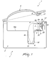
- the apparatus for the vacuum packaging of food products comprises a box-like frame 2, which defines at least one portion of a vacuum chamber 3, which can be connected in a per se known manner to vacuum generation means which are constituted for example by a vacuum pump.
- the vacuum chamber 3 is designed to accommodate a pouch 4 into which the food products to be packaged are placed.
- the pouch 4 is made of plastic material suitable for food use and is provided with at least one heat-sealable portion.
- the vacuum chamber 3 is delimited in a downward region by the box-like frame 2 and is closed in an upward region by a lid 5, which is conveniently pivoted to the box-like frame 2 to allow to lift it and thus allow access from outside to the vacuum chamber 3.
- sealing means 6 are provided which are capable of heat-sealing the pouch substantially at its mouth 4a.
- the sealing means 6 comprise conveniently a heat-sealing bar 7 which has an electrical heating resistor and a contrast bar 8 which is mounted on the lid 5 and is designed to face the heat-sealing bar 7 when the lid 5 is in the closed condition.
- the heat-sealing bar 7, as usual, can be actuated on command in order to move from an inactive position, in which it is spaced from the contrast bar 8, to an active position, in which it is adapted to press the pouch against the contrast bar 8.
- the movement of the heat-sealing bar 7 from the inactive position to the active position can be achieved, in a per se known manner, by means of an inflatable pad 9, which is interposed between the heat-sealing bar 7 and the box-like frame 2. More particularly, the inflatable pad 9 can be connected to an air inflow source which allows to move it from a collapsed condition to an expanded condition, so as to provide the transition of the heat-sealing bar 7 from the inactive position to the active position.
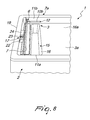
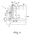
- a peculiar aspect of the invention resides in that the heat-sealing bar 7 is connected so that it can oscillate to the box-like frame 2, about an oscillation axis 7a which is substantially parallel and spaced with respect to the heat-sealing bar 7, so as to allow the passage of the heat-sealing bar 7 from a lowered position, shown in Figure 8, in which the heat-sealing bar 7 is closer to the box-like frame 2, so as to be able to interact for example with the inflatable pad 9, to a raised position, shown in Figure 9, in which the heat-sealing bar 7 is spaced from the box-like frame 2 in order to allow the user to have free access to the vacuum chamber 3 in particular after lifting the lid 5, and vice versa.
- such pad can be provided for example with a quick-coupling nipple 9a which can be inserted in a connecting port 9b which is provided in the bottom wall 3a of the vacuum chamber 3 and is connected to an air duct 9c, which is connected to the outside environment by means of an appropriately provided valve and allows to introduce air in the inflatable pad 9 or to discharge air from it.
- the connecting port 9b can be provided with an appropriately provided plug to close it temporarily during the cleaning of the vacuum chamber.
- the heat-sealing bar 7 is connected to the box-like frame 2 by means of two supporting arms 10a and 10b, which are fixed at one of their ends to a respective end portion of the heat-sealing bar 7 and are articulated at their other end, about the oscillation axis 7a, to a respective lateral delimiting wall 11a, 11b of the vacuum chamber 3.
- each of the supporting arms 10a, 10b is connected to the corresponding lateral delimiting wall 11a, 11b of the vacuum chamber 3 by means of a corresponding articulation hinge 12, which comprises advantageously means for electrical connection to an electric power supply unit for the heat-sealing bar 7, which is arranged conveniently inside the box-like frame 2.
- such electrical connection means are constituted respectively by a male electrical connector 13, which is connected preferably to the corresponding arm 10a, 10b, and by a female electrical connector 14, which is provided on the corresponding lateral delimiting wall 11a, 11b.
- the male electrical connector 13 and the female electrical connector 14 are arranged coaxially to the oscillation axis 7a and can be mutually coupled so that they can rotate about their own axis so as to allow the oscillation of the arms with respect to the box-like frame 2.
- the supporting arms 10a, 10b are made of electrically conducting material in order to connect electrically the end portions of the heat-sealing bar 7 and more particularly its electrical resistor to the electrical connection means cited above, thus achieving the electrical connection of the heat-sealing bar 7 to its power supply unit without the aid of conducting wires as in the background art.
- the heat-sealing bar 7 may also be completely removable from the box-like frame 2 so as to offer even easier access to the vacuum chamber 3.
- the supporting arms 10a, 10b are provided so that they can be flexed elastically away from the corresponding lateral delimiting wall 11a, 11b, so as to be able to uncouple the respective male electrical connector 13 with respect to the corresponding female electrical connector 14 and achieve the disassembly of the heat-sealing bar 7 from the box-like frame 2.
- the vacuum chamber 3 is provided with at least one accommodation region 15 for positioning substantially vertically at least one portion 4b of the pouch 4 which is arranged on the opposite side with respect to the mouth 4a of the pouch 4.
- the accommodation region 15 comprises a recess 16 which is defined in the bottom wall 3a of the vacuum chamber 3 and conveniently is located proximate to the sealing means 6 and more precisely proximate to the heat-sealing bar 7, protruding for example substantially parallel to the heat-sealing bar 7.
- the supporting surface 16a is arranged advantageously on the opposite side of the heat-sealing bar 7 with respect to the recess 16, as shown in the figures.
- Another characteristic of the invention consists in that it provides for the presence of at least one printing device 17, which allows to apply to the pouch 4 indications of various kinds, such as for example the packaging date, the expiration date of the packaged products, the batch number of the resulting package, and so forth.
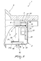
- the printing device 17 is capable of producing a hot imprinting on the pouch 4, as will become better apparent hereinafter.
- the printing device 17 is preferably arranged between the sealing means 6 and the lateral delimiting wall 19 of the vacuum chamber 3, which is adjacent to the sealing means 6 and faces them.
- the indications can be applied by the printing device 17 to a region of the pouch 4 which is comprised between the heat-sealing line provided by the heat-sealing means 6 and its mouth 4a.
- the printing device 17 is connected detachably to the lateral delimiting wall 19 of the vacuum chamber 3.
- a coupling with a slider 20 which can engage slidingly a corresponding accommodation seat 21 which is defined in the body of the printing device 17.
- the printing device 17 is constituted for example by a base 22 which supports a plurality of printing rollers 23, which can rotate axially on command and bear in relief, on their lateral surface, the numbers and/or characters to be imprinted onto the pouch 4.
- the rotation of the printing rollers 23 can be performed manually by the user for example after removing the printing device 17 from the slider coupling 20 or can be performed by actuation means, such as for example an electric motor which can be controlled by means of a selection unit which allows the user to set the indication to be printed on the pouch 4.
- actuation means such as for example an electric motor which can be controlled by means of a selection unit which allows the user to set the indication to be printed on the pouch 4.
- a heatable head 24 faces the printing rollers 23 and is provided with an appropriately provided electrical resistor.
- the head 24 is conveniently connected to the base 22 by means of rods 25 which can slide axially within guiding seats provided in the base 22, in order to allow on command to move the head 24 toward or away with respect to the base 22 between an inactive position, in which it is possible to insert the pouch 4 between the base 22 and the head 24, and an active position, in which the pouch 4 is pressed by the head 24 against the printing rollers 23.
- the rods 25 can optionally provide the electrical connection of the resistor arranged on the head 24 to its electrical power supply, which is preferably accommodated within the base 22 and can be constituted by ordinary batteries or by the mains electrical power supply of the apparatus.
- elastic return means act between the base 22 and the head 24 and are designed to contrast the passage of the head 24 from the inactive position to the active position and are constituted for example by helical springs 26 which are fitted around the rods 25.
- abutment portion 27 which is designed to engage the head 24 during the transition of the lid 5 from the open condition to the closed condition, so as to move the head 24 from the inactive position to the active position, as shown in particular in Figure 6.
- a plate 30 which protrudes laterally from the heat-sealing bar 7 and allows optimum distribution of the thrust provided by the inflatable pad 9 in order to perform the transition of the heat-sealing bar 7 from its inactive position to its active position.
- the plate 30 is constituted advantageously by a first sheet-like element 31, which is fixed to the heat-sealing bar 7 and protrudes laterally from the heat-sealing bar 7 in the opposite direction with respect to the printing device 17, and by a second sheet-like element 32, which is connected, along one edge, to the free end 31a of the first sheet-like element 31 so that it can oscillate freely in order to arrange itself by gravity in a substantially vertical position when the heat-sealing bar 7 is moved to the raised position.
- the lid 5 is opened and the printing device 17 is prepared, for example by extracting it from its slider coupling 20, after first of all bringing the heat-sealing bar 7 to the raised position by way of its rotation about its oscillation axis 7a, and by then turning manually the printing rollers 23, so as to set the indication that one wishes to imprint on the pouch 4 which will be used for vacuum packaging.
- the printing device 17 is repositioned on the slider coupling 20 and, again with the lid 5 in the open condition, the pouch 4 containing the products to be packaged is arranged within the vacuum chamber 3.
- the pouch 4 contains products which might escape from its mouth 4a before it is sealed, the pouch 4 is arranged with its bottom side within the accommodation region 15 and more particularly is inserted in the recess 16, while the mouth 4a is made to pass over the heat-sealing bar 7, which has been previously brought to the lowered position, and is inserted between the head 24 and the base 22 of the printing device 17.
- the lid 5 is closed and rests, with its abutment portion 27, against the head 24 and therefore pushes the head 24 toward the base 22, so that the pouch 4 is pressed by the head 24 against the printing rollers 23.
- the vacuum pump is activated so as to create in the vacuum chamber 3 a negative pressure which allows to extract the air from the pouch 4 through its mouth 4a.
- the valve that controls the air duct 9c of the inflatable pad 9 is opened so as to connect the inside of the inflatable pad 9 to the outside environment. Due to the negative pressure in the vacuum chamber 3, air is drawn into the inflatable pad 9, which by assuming an expanded condition pushes the heat-sealing bar 7 toward the contrast bar 8 until it reaches its active position.
- the resistor of the heat-sealing bar 7 is supplied with electric power so as to heat-seal the pouch 4 and the resistor that is present in the head 24 of the printing device 17 is powered so that the head 24, once it has been heated, allows to provide on the pouch 4 the hot imprinting of the selected indication.
- the lid 5 is opened, allowing the elastic return means to return the head 24 to the inactive position, and the pouch 4 with the vacuum-packaged products contained therein is extracted from the vacuum chamber 3.
- Restoring atmospheric pressure inside the vacuum chamber 3 causes the transition of the inflatable pad 9 from the expanded condition to the collapsed condition, so as to allow the return of the heat-sealing bar 7 to its inactive position due to its own weight.
- the invention achieves, in all of its embodiments, the intended aim and objects and in particular the fact is stressed that thanks to the connection with the possibility to oscillate of the heat-sealing bar with respect to the box-like frame, it allows to move very conveniently and rapidly the heat-sealing bar into a position in which it does not interfere with the maintenance and cleaning operations required for the correct use of the apparatus.
- Another advantage of the invention is to provide a configuration of the apparatus which does not require the presence of conducting wires within the vacuum chamber, thus achieving a positive result also from an aesthetic point of view.
- the invention also offers the great advantage of allowing to apply to the packaged pouch indications which can provide the user with useful information as regards the possibility to eat the vacuum-packaged foodstuffs, such as the expiration date or the packaging date, and this is not available in current apparatuses for professional use.
- the materials used, as well as they are compatible with the specific use, as well as the dimensions and shapes, may be any according to requirements.
Landscapes
- Engineering & Computer Science (AREA)
- Mechanical Engineering (AREA)
- Physics & Mathematics (AREA)
- Fluid Mechanics (AREA)
- Chemical & Material Sciences (AREA)
- Dispersion Chemistry (AREA)
- Vacuum Packaging (AREA)
Priority Applications (1)
| Application Number | Priority Date | Filing Date | Title |
|---|---|---|---|
| EP09179968A EP2208677B1 (de) | 2006-11-24 | 2007-10-22 | Vorrichtung zur Vakuumverpackung von Nahrungsmitteln |
Applications Claiming Priority (1)
| Application Number | Priority Date | Filing Date | Title |
|---|---|---|---|
| IT000181A ITVR20060181A1 (it) | 2006-11-24 | 2006-11-24 | Apparecchiatura per il confezionamento sottovuoto di prodotti alimentari |
Publications (2)
| Publication Number | Publication Date |
|---|---|
| EP1925556A2 true EP1925556A2 (de) | 2008-05-28 |
| EP1925556A3 EP1925556A3 (de) | 2009-07-22 |
Family
ID=39167499
Family Applications (2)
| Application Number | Title | Priority Date | Filing Date |
|---|---|---|---|
| EP09179968A Not-in-force EP2208677B1 (de) | 2006-11-24 | 2007-10-22 | Vorrichtung zur Vakuumverpackung von Nahrungsmitteln |
| EP07020587A Withdrawn EP1925556A3 (de) | 2006-11-24 | 2007-10-22 | Vorrichtung zur Vakuumverpackung von Nahrungsmitteln |
Family Applications Before (1)
| Application Number | Title | Priority Date | Filing Date |
|---|---|---|---|
| EP09179968A Not-in-force EP2208677B1 (de) | 2006-11-24 | 2007-10-22 | Vorrichtung zur Vakuumverpackung von Nahrungsmitteln |
Country Status (2)
| Country | Link |
|---|---|
| EP (2) | EP2208677B1 (de) |
| IT (1) | ITVR20060181A1 (de) |
Cited By (12)
| Publication number | Priority date | Publication date | Assignee | Title |
|---|---|---|---|---|
| CN101973406A (zh) * | 2010-08-16 | 2011-02-16 | 上海嘉迪机械有限公司 | 一种全自动真空包装机 |
| ITTO20120159A1 (it) * | 2012-02-23 | 2012-05-24 | Minipack Torre Spa | MACCHINA CONFEZIONATRICE PER SOTTOVUOTO A CAMERA INTERNA ESTRAIBILE E DI COTTURA A BASSA TEMPERATURA ÂeuroOESOUS VIDEÂeuro¿. |
| EP2832649A4 (de) * | 2012-03-27 | 2015-11-18 | Tosei Corp | Vakuumverpackungsverfahren und vakuumverpackungsvorrichtung |
| CN108466723A (zh) * | 2018-03-29 | 2018-08-31 | 峨眉山神农药材种植有限公司 | 一种中药材包装机构 |
| EP3381662A1 (de) * | 2017-03-28 | 2018-10-03 | MULTIVAC Sepp Haggenmüller SE & Co. KG | Siegelschienentemperaturkompensation |
| CN109914998A (zh) * | 2019-04-11 | 2019-06-21 | 郑荣华 | 真空包装机上盖的连接结构 |
| IT201800003468A1 (it) * | 2018-03-13 | 2019-09-13 | Marziano Salvaro | Macchina confezionatrice di prodotti alimentari in sacchetti sottovuoto. |
| EP3722215A4 (de) * | 2017-12-04 | 2021-01-27 | Xiamen Youo Intelligent Technology Co., Ltd | Vakuumkonservierungsmaschine zum drucken eines datumcodes |
| EP3771651A1 (de) * | 2019-08-01 | 2021-02-03 | Immobles del Segria, S.L. | Detektionssystem und detektionsverfahren zur detektion der betätigung eines deckels in einer vakuumverpackungmaschine |
| EP4026780A1 (de) * | 2021-01-07 | 2022-07-13 | Vestel Elektronik Sanayi ve Ticaret A.S. | Selbstreparierende vakuumvorrichtung |
| WO2022171079A1 (zh) * | 2021-02-10 | 2022-08-18 | 广州亚俊氏真空科技股份有限公司 | 一种多功能真空包装机 |
| IT202100018428A1 (it) * | 2021-07-13 | 2023-01-13 | Sirman S P A | Macchina confezionatrice sottovuoto |
Families Citing this family (2)
| Publication number | Priority date | Publication date | Assignee | Title |
|---|---|---|---|---|
| CN107521748B (zh) * | 2017-09-07 | 2021-01-15 | 广州亚俊氏电器有限公司 | 一种新型真空包装机 |
| CN107719800A (zh) * | 2017-10-18 | 2018-02-23 | 安徽工程大学 | 一种用于食品包装机的喷码装置 |
Family Cites Families (9)
| Publication number | Priority date | Publication date | Assignee | Title |
|---|---|---|---|---|
| FR1322624A (fr) * | 1962-05-17 | 1963-03-29 | Hesser Ag Maschf | Chambre permettant d'évacuer l'air contenu dans des emballages de tous types et de le remplacer par un gaz protecteur |
| FR1384507A (fr) * | 1964-03-07 | 1965-01-04 | Vickers Armstrongs Ltd | Perfectionnements apportés aux appareils d'emballage |
| US4057951A (en) * | 1977-01-28 | 1977-11-15 | Land O'frost Inc. | Packaging machine |
| DE29619396U1 (de) * | 1996-11-08 | 1998-03-05 | Robert Bosch Gmbh, 70469 Stuttgart | Vorrichtung zum Evakuieren und Begasen von gefüllten Packungen |
| DE29703671U1 (de) * | 1997-02-28 | 1997-06-26 | Sammet, Rolf, 73667 Kaisersbach | Vacuumgerät mit Kennzeichnung der Lebensmittelart und des Verfalldatums |
| US20030159405A1 (en) * | 2002-02-28 | 2003-08-28 | Scott Knowlton | Vacuum packaging apparatus and method |
| US7302784B2 (en) * | 2002-09-27 | 2007-12-04 | Depuy Products, Inc. | Vacuum packaging machine |
| US6862867B2 (en) * | 2003-01-16 | 2005-03-08 | Pack-Tech, L.L.C. | Bag sealing system and method |
| JP2005247383A (ja) * | 2004-03-05 | 2005-09-15 | Toshiba Corp | 複合真空調理器 |
-
2006
- 2006-11-24 IT IT000181A patent/ITVR20060181A1/it unknown
-
2007
- 2007-10-22 EP EP09179968A patent/EP2208677B1/de not_active Not-in-force
- 2007-10-22 EP EP07020587A patent/EP1925556A3/de not_active Withdrawn
Cited By (21)
| Publication number | Priority date | Publication date | Assignee | Title |
|---|---|---|---|---|
| CN101973406B (zh) * | 2010-08-16 | 2011-11-09 | 上海嘉迪机械有限公司 | 一种全自动真空包装机 |
| CN101973406A (zh) * | 2010-08-16 | 2011-02-16 | 上海嘉迪机械有限公司 | 一种全自动真空包装机 |
| US20180155073A1 (en) * | 2012-02-23 | 2018-06-07 | Fabio Emanuele Torre | Vacuum Packaging Machine With Removable Internal And Low-Temperature "Sous Vide" Cooking Chamber |
| ITTO20120159A1 (it) * | 2012-02-23 | 2012-05-24 | Minipack Torre Spa | MACCHINA CONFEZIONATRICE PER SOTTOVUOTO A CAMERA INTERNA ESTRAIBILE E DI COTTURA A BASSA TEMPERATURA ÂeuroOESOUS VIDEÂeuro¿. |
| WO2013124872A1 (en) * | 2012-02-23 | 2013-08-29 | Mini Pack-Torre S.P.A. | Vacuum packaging machine with removable internal and low-temperature "sous vide" cooking chamber |
| US20150040516A1 (en) * | 2012-02-23 | 2015-02-12 | Mini Pack-Torre S.P.A. | Vacuum Packaging Machine With Removable Internal And Low-Temperature "Sous Vide" Cooking Chamber |
| US10988271B2 (en) | 2012-03-27 | 2021-04-27 | Tosei Corporation | Vacuum packaging method and vacuum packaging apparatus |
| EP3192742A1 (de) * | 2012-03-27 | 2017-07-19 | Tosei Corporation | Vakuumverpackungsverfahren und vakuumverpackungsvorrichtung |
| US9994342B2 (en) | 2012-03-27 | 2018-06-12 | Tosei Corporation | Vacuum packaging method and vacuum packaging apparatus |
| EP2832649A4 (de) * | 2012-03-27 | 2015-11-18 | Tosei Corp | Vakuumverpackungsverfahren und vakuumverpackungsvorrichtung |
| EP3381662A1 (de) * | 2017-03-28 | 2018-10-03 | MULTIVAC Sepp Haggenmüller SE & Co. KG | Siegelschienentemperaturkompensation |
| EP3722215A4 (de) * | 2017-12-04 | 2021-01-27 | Xiamen Youo Intelligent Technology Co., Ltd | Vakuumkonservierungsmaschine zum drucken eines datumcodes |
| IT201800003468A1 (it) * | 2018-03-13 | 2019-09-13 | Marziano Salvaro | Macchina confezionatrice di prodotti alimentari in sacchetti sottovuoto. |
| CN108466723A (zh) * | 2018-03-29 | 2018-08-31 | 峨眉山神农药材种植有限公司 | 一种中药材包装机构 |
| CN109914998A (zh) * | 2019-04-11 | 2019-06-21 | 郑荣华 | 真空包装机上盖的连接结构 |
| EP3771651A1 (de) * | 2019-08-01 | 2021-02-03 | Immobles del Segria, S.L. | Detektionssystem und detektionsverfahren zur detektion der betätigung eines deckels in einer vakuumverpackungmaschine |
| EP4026780A1 (de) * | 2021-01-07 | 2022-07-13 | Vestel Elektronik Sanayi ve Ticaret A.S. | Selbstreparierende vakuumvorrichtung |
| WO2022171079A1 (zh) * | 2021-02-10 | 2022-08-18 | 广州亚俊氏真空科技股份有限公司 | 一种多功能真空包装机 |
| IT202100018428A1 (it) * | 2021-07-13 | 2023-01-13 | Sirman S P A | Macchina confezionatrice sottovuoto |
| WO2023286091A1 (en) * | 2021-07-13 | 2023-01-19 | Sirman S.P.A. | Vacuum packaging machine |
| US12269632B2 (en) | 2021-07-13 | 2025-04-08 | Sirman S.P.A. | Vacuum packaging machine |
Also Published As
| Publication number | Publication date |
|---|---|
| EP2208677B1 (de) | 2012-05-30 |
| ITVR20060181A1 (it) | 2008-05-25 |
| EP2208677A1 (de) | 2010-07-21 |
| EP1925556A3 (de) | 2009-07-22 |
Similar Documents
| Publication | Publication Date | Title |
|---|---|---|
| EP2208677B1 (de) | Vorrichtung zur Vakuumverpackung von Nahrungsmitteln | |
| US7484346B2 (en) | Vacuum packaging appliance with removable trough | |
| EP0723915B1 (de) | Vorrichtung zum Vakuumverpacken von Gegenständen in flexiblen Beuteln | |
| US7003928B2 (en) | Appliance for vacuum sealing food containers | |
| US7076929B2 (en) | Appliance for vacuum sealing food containers | |
| CN100548816C (zh) | 具有可分开和可清洗的液体回收盘的用于在容器中形成真空的装置 | |
| US8033430B2 (en) | Pot-type heated fluid dispenser | |
| US3452513A (en) | Heater construction for closing packages | |
| KR101529159B1 (ko) | 다양한 크기의 식품용기를 포장할 수 있는 식품용기 포장장치 | |
| KR101269947B1 (ko) | 용기 실링기능과 진공포장기능을 갖는 포장기 | |
| CN100413438C (zh) | 物料自动投放系统、其所用物料包装以及相应的烹调器具 | |
| KR20090075582A (ko) | 일회용 식품용기의 밀봉포장 장치 | |
| CN211066217U (zh) | 一种自动餐饮设备 | |
| KR102214784B1 (ko) | 휴대용 진공 포장기 | |
| EP1990280A1 (de) | Vorrichtung zur Herstellung eines Vakuums in Behältern zur Aufbewahrung von Lebensmitteln | |
| CN211056134U (zh) | 一种传送机构及自动餐饮设备 | |
| CN218419384U (zh) | 一种慢煮锅 | |
| CN213974681U (zh) | 一种设封板的取包装袋机构 | |
| CN111772458B (zh) | 低温烹饪机 | |
| CN215205696U (zh) | 一种真空封口机 | |
| CN210930920U (zh) | 一种蒸汽发生器及自动餐饮设备 | |
| CN201343170Y (zh) | 过滤纸盒热粘机 | |
| CA2501342A1 (en) | Appliance for vacuum sealing food containers | |
| CN206218296U (zh) | 杯、盒通用的食品用真空腔体 | |
| KR20230108410A (ko) | 다기능 포장기 |
Legal Events
| Date | Code | Title | Description |
|---|---|---|---|
| PUAI | Public reference made under article 153(3) epc to a published international application that has entered the european phase |
Free format text: ORIGINAL CODE: 0009012 |
|
| AK | Designated contracting states |
Kind code of ref document: A2 Designated state(s): AT BE BG CH CY CZ DE DK EE ES FI FR GB GR HU IE IS IT LI LT LU LV MC MT NL PL PT RO SE SI SK TR |
|
| AX | Request for extension of the european patent |
Extension state: AL BA HR MK RS |
|
| PUAL | Search report despatched |
Free format text: ORIGINAL CODE: 0009013 |
|
| AK | Designated contracting states |
Kind code of ref document: A3 Designated state(s): AT BE BG CH CY CZ DE DK EE ES FI FR GB GR HU IE IS IT LI LT LU LV MC MT NL PL PT RO SE SI SK TR |
|
| AX | Request for extension of the european patent |
Extension state: AL BA HR MK RS |
|
| AKX | Designation fees paid | ||
| REG | Reference to a national code |
Ref country code: DE Ref legal event code: 8566 |
|
| STAA | Information on the status of an ep patent application or granted ep patent |
Free format text: STATUS: THE APPLICATION IS DEEMED TO BE WITHDRAWN |
|
| 18D | Application deemed to be withdrawn |
Effective date: 20100123 |