EP1925497A2 - Vehicle headlight leveling device and vehicle headlight equipped with leveling device - Google Patents
Vehicle headlight leveling device and vehicle headlight equipped with leveling device Download PDFInfo
- Publication number
- EP1925497A2 EP1925497A2 EP07022762A EP07022762A EP1925497A2 EP 1925497 A2 EP1925497 A2 EP 1925497A2 EP 07022762 A EP07022762 A EP 07022762A EP 07022762 A EP07022762 A EP 07022762A EP 1925497 A2 EP1925497 A2 EP 1925497A2
- Authority
- EP
- European Patent Office
- Prior art keywords
- shaft
- forth
- respect
- motor
- housing unit
- Prior art date
- Legal status (The legal status is an assumption and is not a legal conclusion. Google has not performed a legal analysis and makes no representation as to the accuracy of the status listed.)
- Granted
Links
- 230000003287 optical effect Effects 0.000 claims description 25
- 230000002093 peripheral effect Effects 0.000 description 9
- 239000003990 capacitor Substances 0.000 description 1
- 238000010276 construction Methods 0.000 description 1
- 230000000694 effects Effects 0.000 description 1
- 238000005516 engineering process Methods 0.000 description 1
- 229910052736 halogen Inorganic materials 0.000 description 1
- 150000002367 halogens Chemical class 0.000 description 1
- 238000012986 modification Methods 0.000 description 1
- 230000004048 modification Effects 0.000 description 1
- 239000004065 semiconductor Substances 0.000 description 1
Images


Classifications
-
- B—PERFORMING OPERATIONS; TRANSPORTING
- B60—VEHICLES IN GENERAL
- B60Q—ARRANGEMENT OF SIGNALLING OR LIGHTING DEVICES, THE MOUNTING OR SUPPORTING THEREOF OR CIRCUITS THEREFOR, FOR VEHICLES IN GENERAL
- B60Q1/00—Arrangement of optical signalling or lighting devices, the mounting or supporting thereof or circuits therefor
- B60Q1/02—Arrangement of optical signalling or lighting devices, the mounting or supporting thereof or circuits therefor the devices being primarily intended to illuminate the way ahead or to illuminate other areas of way or environments
- B60Q1/04—Arrangement of optical signalling or lighting devices, the mounting or supporting thereof or circuits therefor the devices being primarily intended to illuminate the way ahead or to illuminate other areas of way or environments the devices being headlights
- B60Q1/06—Arrangement of optical signalling or lighting devices, the mounting or supporting thereof or circuits therefor the devices being primarily intended to illuminate the way ahead or to illuminate other areas of way or environments the devices being headlights adjustable, e.g. remotely-controlled from inside vehicle
- B60Q1/076—Arrangement of optical signalling or lighting devices, the mounting or supporting thereof or circuits therefor the devices being primarily intended to illuminate the way ahead or to illuminate other areas of way or environments the devices being headlights adjustable, e.g. remotely-controlled from inside vehicle by electrical means including means to transmit the movements, e.g. shafts or joints
Definitions
- the present invention relates to a vehicle headlight leveling device and a vehicle headlight that includes the leveling device.
- a conventional leveling device for a vehicle headlight such as a headlamp and a fog lamp is disclosed, for example, in Japanese Patent Application Laid-open No. 2001-163116 .
- the conventional leveling device includes a casing, a motor arranged in the casing, and a shaft that moves back and forth by rotation of the motor.
- the motor and a circuit member that includes terminals for supplying an electric power to the motor are arranged on different sides with respect to a virtual surface that includes the shaft. When the motor is driven, the shaft moves back and forth to adjust an optical axis of the vehicle headlight.
- a left-side leveling device positions of terminals of the leveling device built in the left-side vehicle headlight (hereinafter, a left-side leveling device) and terminals of the leveling device built in the right-side vehicle headlight (hereinafter, a right-side leveling device) are biased on one side, either the left side or the right side with respect to each of the shafts.
- positions of connectors and lengths of harnesses for the terminals of the left-side leveling device and the terminals of the right-side leveling device differ from each other, resulting in a difference between the left-side vehicle headlight and the right-side vehicle headlight in a design and a layout of the connector and the harness. Consequently, it is difficult to have specifications of the left-side headlight and the right-side headlight in common.
- a device for adjusting an optical axis of a headlight of a vehicle includes a housing unit; a motor that is arranged in the housing unit; a shaft that moves back and forth with respect to the housing unit; a driving-force transmitting mechanism that is arranged between the motor and the shaft, and that transmits a driving force of the motor to the shaft; and a plurality of terminals for supplying an electric power to the motor.
- An axial direction of an output shaft of the motor is perpendicular or substantially perpendicular to an axial direction of the shaft.
- a shape of a layout of the terminals is substantially symmetric with respect to a vertical line passing through a center of the shaft.
- a vehicle headlight includes a fixing member; a tilting member that is mounted on the fixing member in a tiltable manner; and a leveling device for adjusting an optical axis of the vehicle headlight.
- the leveling device includes a housing unit, a motor that is arranged in the housing unit, a shaft that moves back and forth with respect to the housing unit, a driving-force transmitting mechanism that is arranged between the motor and the shaft, and that transmits a driving force of the motor to the shaft, and a plurality of terminals for supplying an electric power to the motor.
- the leveling device is arranged between the fixing member and the tilting member.
- An axial direction of an output shaft of the motor is perpendicular or substantially perpendicular to an axial direction of the shaft.
- a shape of a layout of the terminals is substantially symmetric with respect to a vertical line passing through a center of the shaft.
- the housing unit is attached to the fixing member.
- the shaft is mounted on the tilting member.
- the tilting member is tilted with respect to the fixing member through an operation of the leveling device to adjust the optical axis.
- a vehicle headlight leveling device and a vehicle headlight including the leveling device according to an embodiment of the present invention are explained by referring to Fig. 5.
- Fig. 5 is a vertical cross section of a headlamp 1 for explaining an operation of adjusting an optical axis in an up-and-down direction of the headlamp 1.
- the headlamp 1 is a head light of a vehicle.
- the headlamp 1 includes a lamp housing 3 as a fixing member and a lamp lens 4 that divides a lamp chamber 2, an mounting bracket 5 as a tilting member that is arranged in the lamp chamber 2, and a leveling device 6 arranged between the lamp housing 3 and the mounting bracket 5.
- the tilting member includes at least one lamp unit (not shown) and the mounting bracket 5 on which the lamp unit is mounted.
- the lamp unit is, for example, a projection type, a reflection type, or a direct projection-type lamp unit.
- the lamp unit emits a light from a light source (a semiconductor light source such as a light emitting diode (LED), a discharge lamp such as a high intensity discharge (HID) lamp, a halogen bulb, and an incandescent bulb) along a predetermined optical axis through the lamp lens 4 in a front direction of a vehicle in a predetermined light distribution pattern.
- a component of the lamp unit for example, a reflector can be also used as the mounting bracket 5.
- the mounting bracket 5 is attached to the lamp housing 3 via the leveling device 6 and a pivot mechanism 7 in a swingable manner up and down relative to a horizontal line H that passes through a center of a pivoting portion 8 of the pivot mechanism 7.
- An optical axis adjusting mechanism (not shown) for a lateral movement can be arranged between the lamp housing 3 and the mounting bracket 5.
- the tilting member can be arranged to adjust an optical axis left and right relative to a vertical line V that passes through the center of the pivoting portion 8.
- the leveling device 6 includes a housing unit including a front housing 9 and a rear housing 10, a motor 11, a shaft 12, a driving-force transmitting mechanism 13, and a plurality of power-supplying terminals 14 (three terminals are employed in the present embodiment).
- the housing unit is divided into the front housing 9 and the rear housing 10, and the housing 9 and the housing 10 are detachably integrated or fixed to form the housing unit.
- the housings 9 and 10 are attached to the lamp housing 3.
- a cylindrical portion 15 is integrally arranged substantially in the middle of an upper portion on an outer side of the front housing 9.
- a screw hole 16 is formed on an inner peripheral surface of the cylindrical portion 15.
- At least one convex portion 17 that prevents a first rod 33 from rotating is integrally arranged on the inner peripheral surface of the top of the cylindrical portion 15.
- a holding portion 18 for holding the motor 11 is integrally arranged substantially in the middle of an inner side of the front housing 9.
- Bearing portions 19 are arranged at an upper portion and a middle portion on the inner side of the front housing 9.
- a forked arm portion 20 that prevents a second rod 34 from rotating is integrally arranged substantially in the middle of the upper portion on the inner side of the housing 10 so that the forked arm portion 20 is aligned with an upper edge of the cylindrical portion 15.
- a small cylindrical portion 21 is integrally arranged substantially in the middle of an upper portion on an outer side of the rear housing 10 to be on the same axis of the cylindrical portion 15 of the front housing 9.
- a concave 22 for inserting a connector is formed substantially in the middle of a lower portion on the outer side of the rear housing 10.
- the motor 11 includes an output shaft 23.
- the motor 11 that is held by the holding portion 18 is arranged in the housings 9 and 10.
- the shaft 12 that is an adjust screw is arranged in the cylindrical portion 15 and the small cylindrical portion 21 via the driving-force transmitting mechanism 13 and a crown gear 24 so that the shaft 12 moves back and forth, that is, in an axial direction V1 of the shaft 12 and rotates with respect to the housings 9 and 10.
- a screw portion 25 is arranged at one end (a front end) of the shaft 12.
- a ring-shaped groove 26 is formed substantially in the middle of the shaft 12.
- a nut member 28 (a nut or a screw mounting) is screwed onto the screw portion 25 to move in the axial direction V1 (in a direction of a left-right arrow indicated by a solid line in Fig. 5). Because the nut member 28 is mounted on the mounting bracket 5, the shaft 12 is connected through the nut member 28 to the mounting bracket 5.
- the housings 9 and 10 are attached to the lamp housing 3. Therefore, the leveling device 6 is arranged between the lamp housing 3 as the fixing member and the mounting bracket 5.
- the tilting member including the mounting bracket 5 tilts up and down relative to the horizontal line H in a direction of a curved left-right arrow indicated by a two-dot chain line, so that an optical axis of the headlamp 1 is adjusted.
- the driving-force transmitting mechanism 13 includes a first gear 29, a second gear 30, a worm 31 as a third gear, a worm wheel 32, and a cylindrical rod unit including the first rod 33 on one end side (a front end side) and the second rod 34 on the other end side (a rear end side).
- the first rod 33 and the second rod 34 are detachably integrated or fixed to constitute the cylindrical rod unit.
- the driving-force transmitting mechanism 13 is arranged between the motor 11 and the shaft 12 in the housings 9 and 10.
- a driving force of the motor 11 is transmitted to the shaft 12 via the driving-force transmitting mechanism 13 so that the shaft 12 moves back and forth with respect to the housings 9 and 10 in the direction (in the axial direction V1) of the left-right arrow indicated by the solid line in Fig. 5.
- the first gear 29 is fixed to the output shaft 23 of the motor 11.
- the second gear 30 and the worm 31 are integrally formed and are rotatably supported by the bearing portions 19.
- the first gear 29 and the second gear 30 mesh with each other.
- a worm wheel portion 35 is arranged on an outer peripheral surface of one end (a rear end) of the worm wheel 32.
- a screw portion 36 is arranged on an outer peripheral surface of the other end (a front end) of the worm wheel 32.
- the screw portion 36 is screwed into the screw hole 16 of the front housing 9 in the direction in which the shaft 12 moves back and forth.
- the worm wheel portion 35 meshes with the worm 31. Consequently, the worm wheel 32 moves back and forth with the shaft 12 and the rods 33 and 34 while rotating with respect to the housing 9 and 10 by a screw movement between the screw hole 16 and the screw portion 36 via the first gear 29, the second gear 30, the worm 31, and the worm wheel portion 35 by driving the motor 11.
- At least one groove portion 37 that prevents the first rod 33 from rotating is arranged on an outer peripheral surface of the top of the first rod 33, and is engaged with the convex portion 17.
- a ring-shaped pressing portion 38 is integrally formed substantially in the middle of the outer peripheral surface of the first rod 33.
- a ring-shaped convex portion 39 that engages with the ring-shaped groove 26 is integrally formed substantially in the middle of an inner peripheral surface of the first rod 33.
- a protrusion portion 40 that prevents the second rod 34 from rotating and presses the worm wheel 32 is integrally arranged on an outer peripheral surface of the top of the second rod 34 in a radial direction of the second rod 34, and is engaged with the forked arm portion 20.
- the protrusion portion 40 is T-shaped when viewed from the front.
- a connection portion 41 is arranged on the outer peripheral surface of the top of the second rod 34 in the radial direction to make a predetermined angle (90 degrees in the present embodiment) with respect to the protrusion portion 40.
- the convex portion 17 is engaged with the groove portion 37 of the first rod 33.
- the protrusion portion 40 is engaged with a middle groove of the forked arm portion 20. Therefore, the rods 33 and 34 are arranged in such a manner that the rods 33 and 34 do not rotate with respect to the housings 9 and 10 while moving in the direction in which the shaft 12 moves (in the axial direction V1).
- the rods 33 and 34 are inserted into the worm wheel 32.
- the ring-shaped pressing portion 38 of the first rod 33 and the protrusion portion 40 of the second rod 34 press against both ends of the worm wheel 32.
- the rods 33 and 34 are arranged in the worm wheel 32 so that the rods 33 and 34 rotate and do not move in the back and forth direction of the shaft 12 with respect to the worm wheel 32.
- the rods 33 and 34 move back and forth with the worm wheel 32 and the shaft 12 without rotating with respect to the housings 9 and 10.
- the shaft 12 is inserted into the rods 33 and 34.
- the ring-shaped groove 26 and the ring-shaped convex portion 39 are engaged with each other. Consequently, the shaft 12 is arranged in such a manner that the shaft 12 rotates and do not move in the axial direction V1 with respect to the rods 33 and 34.
- the shaft 12 moves back and forth in the axial direction V1 with the worm wheel 32 and the rods 33 and 34.
- the crown gear 24 includes a crown gear portion 42, a cylindrical shaft portion 43, and a hexagonal head portion 44.
- the cylindrical shaft portion 43 is integrally formed on one disk-shaped surface (a front surface) of the crown gear portion 42.
- the hexagonal head portion 44 is integrally formed on the other disk-shaped surface (a rear surface) of the crown gear portion 42.
- a chamfered groove 45 that includes two planes and prevents the shaft 12 from rotating is formed from one end surface (a front end surface) of the cylindrical shaft portion 43 to the other end surface (a rear end surface) of the hexagonal head portion 44.
- the cylindrical shaft portion 43 is arranged in the small cylindrical portion 21, so that the cylindrical shaft portion 43 rotates and without moving in an axial direction (in the axial direction V1) of the small cylindrical portion 21 and the cylindrical shaft portion 43.
- the chamfered portion 27 is inserted into the chamfered groove 45. Consequently, the shaft 12 cannot rotate but can move back and forth in the axial direction V1 with respect to the crown gear 24. Thus, the shaft 12 rotates together with the crown gear 24 with respect to the housing 9 and 10 by manually rotating the crown gear 24.
- the shaft 12 is arranged in such a manner that the shaft 12 moves back and forth in the axial direction V1 and rotates with respect to the housings 9 and 10 through the driving-force transmitting mechanism 13 (the worm wheel 32 and the rods 33 and 34) and the crown gear 24. Consequently, the shaft 12 moves back and forth in the direction of the left-right arrow (in the axial direction V1) indicated by the solid line in Fig. 5 with respect to the housings 9 and 10 by driving the motor 11 and rotates with the crown gear 24 with respect to the housings 9 and 10 by manually rotating the crown gear 24.
- an axial direction V2 of the output shaft 23 is perpendicular to the axial direction V1.
- the motor 11 is arranged between the shaft 12 and the power-supplying terminals 14. An electric power is supplied from the power-supplying terminals 14 to the motor 11.
- the power-supplying terminals 14 are attached to a printed circuit board 46 mounted on the housings 9 and 10. As shown in Fig. 3, a shape of a layout of the power-supplying terminals 14 is symmetric relative to a vertical line V3 that passes a center of the shaft 12. Electronic components (not shown) such as a capacitor and a hybrid IC are mounted on the printed circuit board 46.
- a position sensor 47 is arranged between the printed circuit board 46 and the second rod 34.
- the position sensor 47 utilizing a sliding resistor includes a sliding portion 49 and a body portion 48 that incorporates a resistor.
- the body portion 48 is attached to the printed circuit board 46.
- the sliding portion 49 that is connected to the connection portion 41 moves with the second rod 34, so that a resistance of the resistor in the body portion 48 varies.
- a moving amount of the sliding portion 49 that is, a tilting angle of the optical axis of the headlamp 1 in the vertical direction, can be measured based on the variation of the resistance.
- an optical axis of the headlamp 1 in an up-and-down direction can be automatically adjusted in response to variation of a direction of a vehicle.
- the chamfered groove 45 of the crown gear 24 is engaged with the chamfered portion 27 of the shaft 12, so that the shaft 12 rotates.
- the shaft 12 is inserted into the rods 33 and 34, and the ring-shaped groove 26 of the shaft 12 and the ring-shaped convex portion 39 of the first rod 33 are engaged with each other. Therefore, the shaft 12 rotates without moving back and forth in the axial direction V1 with respect to the rods 33 and 34, and the rods 33 and 34 do not rotate. Thus, the rotation of the shaft 12 does not affect the driving-force transmitting mechanism 13 and the motor 11 through the rods 33 and 34.
- a light from the light source is emitted along a predetermined optical axis through the lamp lens 4 forward of a vehicle in a predetermined distribution pattern.
- the controller of the auto-leveling system detects a change of the direction and drives the motor 11.
- a driving force of the motor 11, that is, a rotating force of the output shaft 23 is transmitted to the worm wheel 32 through the first gear 29, the second gear 30, the worm 31, and the worm wheel portion 35. Because the screw portion 36 of the worm wheel 32 is screwed into the screw hole 16 of the housing 9, the worm wheel 32 moves back and forth in the axial direction V1 while rotating with respect to the housing 9 and 10 by a screw movement.
- Both ends of the worm wheel 32 are sandwiched between the ring-shaped pressing portion 38 and the protrusion portion 40, so that the rods 33 and 34 move back and forth in the axial direction V1 with the worm wheel 32 with respect to the housing 9 and 10.
- the groove portion 37 is engaged with the convex portion 17.
- the protrusion portion 40 is engaged with the forked arm portion 20.
- the rod 33 and 34 are inserted into the worm wheel 32. Therefore, the back-and-forth movement of the worm wheel 32 is transmitted to the rods 33 and 34 without the rotating force of the worm wheel 32 being transmitted to the rods 33 and 34. Consequently, the rods 33 and 34 move back and forth with the worm wheel 32 without making a rotation with respect to the housings 9 and 10.
- the ring-shaped convex portion 39 and the ring-shaped groove 26 are engaged with each other, so that the shaft 12 moves back and forth with the rods 33 and 34 and the worm wheel 32 in the axial direction V1 with respect to the housings 9 and 10.
- the shaft 12 is inserted into the rods 33 and 34, the chamfered portion 27 is inserted into the chamfered groove 45, and the crown gear 24 is mounted on the rear housing 10 in such a manner that the crown gear 24 can not move back and forth in the axial direction V1.
- the shaft 12 moves back and forth with the worm wheel 32 and the rods 33 and 34 without rotating with respect to the housings 9 and 10.
- the nut member 28 is screwed onto the screw portion 25. Therefore, when the shaft 12 moves back and forth with respect to the housings 9 and 10 in the direction (in the axial direction V1) of the left-right arrow indicated by the solid line in Fig. 5 by driving the motor 11, the nut member 28 moves back and forth with the back-and-forth movement of the shaft 12 in the direction of the left-right arrow indicated by the broken line in Fig. 5. Consequently, the tilting member that includes the mounting bracket 5 tilts up and down relative to the horizontal line H in the direction of the curved left-right arrow indicated by the two-dot chain line in Fig. 5, so that an optical axis of the headlamp 1 is automatically adjusted in response to a change of a direction of a vehicle.
- a shape of a layout of the power-supplying terminals 14 is symmetric relative to the vertical line V3 passing through the center of the shaft 12. Therefore, it is possible to have specifications of the left-side leveling device and the right-side leveling device in common.
- the power-supplying terminals 14 of the left-side leveling device 6 and the power-supplying terminals 14 of the right-side leveling device 6 are each symmetric in shape of a layout relative to the vertical line V3 passing through the center of the shaft 12.
- a position of a connector (not shown) connected to the power-supplying terminals 14 of the left-side leveling device 6 and a position of a connector (not shown) connected to the power-supplying terminals 14 of the right-side leveling device 6 are the same.
- a length of a harness (not shown) connected to the power-supplying terminals 14 of the left-side leveling device 6 and a length of a harness (not shown) connected to the power-supplying terminals 14 of the right-side leveling device 6 are the same.
- connectors and harnesses can be the same in design and layout in the left-side vehicle headlight and the right-side vehicle headlight, so that the left-side vehicle headlight and the right-side vehicle headlight can be in common .
- the axial direction V2 of the output shaft 23 is perpendicular to the axial direction V1 of the shaft 12. Accordingly, compared with a leveling device in which an axial direction of an output shaft of a motor and an axial direction of a shaft are the same, the housings 9 and 10 can be reduced in thickness (a length in the direction in which the shaft 12 moves back and forth), thereby reducing the size of the leveling device.
- the motor 11 is arranged between the shaft 12 and the power-supplying terminals 14. Therefore, the driving-force transmitting mechanism 13 is positioned on a side in which the motor 11 and the shaft 12 are arranged and a room can be obtained to accommodate control components for driving the motor on a side in which the power-supplying terminals 14 are arranged, thereby further reducing the size of the leveling device.
- the worm wheel 32 moves back and forth with the shaft 12 by a screw movement caused by driving the motor 11 while rotating with respect to the housings 9 and 10.
- the leveling device 6 enables the shaft 12 to reliably move back and forth with respect to the housings 9 and 10 and an optical axis to be reliably adjusted.
- the position sensor 47 arranged between the printed circuit board 46 and the second rod 34 enables an optical axis to be accurately adjusted.
- the shaft 12 can be manually rotated with respect to the housings 9 and 10 to adjust an optical axis, an initial setting can be performed apart from automatic adjustment of an optical axis by driving the motor 11.
- the headlamp 1 as the vehicle headlight includes the leveling device 6, the headlamp 1 can achieve substantially the same effect as that of the leveling device 6.
- the leveling device 6 can be also applied to a vehicle headlight other than the headlamp 1.
- rods 33 and 34 are interposed between the shaft 12 and the worm wheel 32 in the embodiment, the shaft 12 and the worm wheel 32 can be arranged without interposing the rods.
- the position sensor 47 is provided in the embodiment, the position sensor 47 can be eliminated.
- an optical axis can be adjusted by manually rotating the shaft 12 by using the crown gear 24 in the embodiment, the adjustment of an optical axis may not be performed by manually rotating the shaft 12.
- the lamp housing 3 is used as a fixing member and the lamp unit and the mounting bracket 5 are used as a tilting member in the embodiment, a vehicle body can be used as a fixing member and the whole vehicle headlight can be used as a tilting member.
Abstract
Description
- The present application claims priority to and incorporates by reference the entire contents of
Japanese priority document 2006-317313 - The present invention relates to a vehicle headlight leveling device and a vehicle headlight that includes the leveling device.
- A conventional leveling device for a vehicle headlight such as a headlamp and a fog lamp is disclosed, for example, in
Japanese Patent Application Laid-open No. 2001-163116 - Because the motor and the terminals are arranged on different sides with respect to the virtual surface that includes the shaft, when the conventional leveling device is used in a left-side vehicle headlight and in a right-side vehicle headlight, positions of terminals of the leveling device built in the left-side vehicle headlight (hereinafter, a left-side leveling device) and terminals of the leveling device built in the right-side vehicle headlight (hereinafter, a right-side leveling device) are biased on one side, either the left side or the right side with respect to each of the shafts. Thus, positions of connectors and lengths of harnesses for the terminals of the left-side leveling device and the terminals of the right-side leveling device differ from each other, resulting in a difference between the left-side vehicle headlight and the right-side vehicle headlight in a design and a layout of the connector and the harness. Consequently, it is difficult to have specifications of the left-side headlight and the right-side headlight in common.
- It is an object of the present invention to at least partially solve the problems in the conventional technology
- A device for adjusting an optical axis of a headlight of a vehicle, according to one aspect of the present invention, includes a housing unit; a motor that is arranged in the housing unit; a shaft that moves back and forth with respect to the housing unit; a driving-force transmitting mechanism that is arranged between the motor and the shaft, and that transmits a driving force of the motor to the shaft; and a plurality of terminals for supplying an electric power to the motor. An axial direction of an output shaft of the motor is perpendicular or substantially perpendicular to an axial direction of the shaft. A shape of a layout of the terminals is substantially symmetric with respect to a vertical line passing through a center of the shaft.
- A vehicle headlight according to another aspect of the present invention includes a fixing member; a tilting member that is mounted on the fixing member in a tiltable manner; and a leveling device for adjusting an optical axis of the vehicle headlight. The leveling device includes a housing unit, a motor that is arranged in the housing unit, a shaft that moves back and forth with respect to the housing unit, a driving-force transmitting mechanism that is arranged between the motor and the shaft, and that transmits a driving force of the motor to the shaft, and a plurality of terminals for supplying an electric power to the motor. The leveling device is arranged between the fixing member and the tilting member. An axial direction of an output shaft of the motor is perpendicular or substantially perpendicular to an axial direction of the shaft. A shape of a layout of the terminals is substantially symmetric with respect to a vertical line passing through a center of the shaft. The housing unit is attached to the fixing member. The shaft is mounted on the tilting member. The tilting member is tilted with respect to the fixing member through an operation of the leveling device to adjust the optical axis.
-
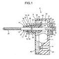
- Fig. 1 is a vertical cross section of a leveling device for a vehicle headlight according to an embodiment of the present invention;
- Fig. 2 is a vertical cross section of the leveling device in which a shaft shown in Fig. 1 recedes;
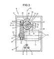
- Fig. 3 is a rear view of the leveling device with a rear housing and a crown gear removed, representing an inside of a front housing of the leveling device;
- Fig. 4 is an exploded perspective view of components of the leveling device shown in Fig. 1; and
- Fig. 5 is a vertical cross section of a headlamp for explaining an operation of adjusting an optical axis in an up-and-down direction of the headlamp.
- Exemplary embodiments of the present invention are explained in detail below with reference to the accompanying drawings.
- A vehicle headlight leveling device and a vehicle headlight including the leveling device according to an embodiment of the present invention are explained by referring to Fig. 5.
- Fig. 5 is a vertical cross section of a
headlamp 1 for explaining an operation of adjusting an optical axis in an up-and-down direction of theheadlamp 1. In the example shown in Fig. 5, theheadlamp 1 is a head light of a vehicle. As shown in Fig. 5, theheadlamp 1 includes alamp housing 3 as a fixing member and alamp lens 4 that divides alamp chamber 2, anmounting bracket 5 as a tilting member that is arranged in thelamp chamber 2, and aleveling device 6 arranged between thelamp housing 3 and themounting bracket 5. - The tilting member includes at least one lamp unit (not shown) and the
mounting bracket 5 on which the lamp unit is mounted. The lamp unit is, for example, a projection type, a reflection type, or a direct projection-type lamp unit. The lamp unit emits a light from a light source (a semiconductor light source such as a light emitting diode (LED), a discharge lamp such as a high intensity discharge (HID) lamp, a halogen bulb, and an incandescent bulb) along a predetermined optical axis through thelamp lens 4 in a front direction of a vehicle in a predetermined light distribution pattern. A component of the lamp unit, for example, a reflector can be also used as themounting bracket 5. - The
mounting bracket 5 is attached to thelamp housing 3 via theleveling device 6 and apivot mechanism 7 in a swingable manner up and down relative to a horizontal line H that passes through a center of apivoting portion 8 of thepivot mechanism 7. An optical axis adjusting mechanism (not shown) for a lateral movement can be arranged between thelamp housing 3 and themounting bracket 5. The tilting member can be arranged to adjust an optical axis left and right relative to a vertical line V that passes through the center of thepivoting portion 8. - As shown in Fig. 4, the
leveling device 6 includes a housing unit including afront housing 9 and arear housing 10, amotor 11, ashaft 12, a driving-force transmitting mechanism 13, and a plurality of power-supplying terminals 14 (three terminals are employed in the present embodiment). - The housing unit is divided into the
front housing 9 and therear housing 10, and thehousing 9 and thehousing 10 are detachably integrated or fixed to form the housing unit. Thehousings lamp housing 3. - A
cylindrical portion 15 is integrally arranged substantially in the middle of an upper portion on an outer side of thefront housing 9. A screw hole 16 is formed on an inner peripheral surface of thecylindrical portion 15. At least oneconvex portion 17 that prevents afirst rod 33 from rotating is integrally arranged on the inner peripheral surface of the top of thecylindrical portion 15. Aholding portion 18 for holding themotor 11 is integrally arranged substantially in the middle of an inner side of thefront housing 9. Bearingportions 19 are arranged at an upper portion and a middle portion on the inner side of thefront housing 9. Furthermore, a forkedarm portion 20 that prevents asecond rod 34 from rotating is integrally arranged substantially in the middle of the upper portion on the inner side of thehousing 10 so that the forkedarm portion 20 is aligned with an upper edge of thecylindrical portion 15. - A small
cylindrical portion 21 is integrally arranged substantially in the middle of an upper portion on an outer side of therear housing 10 to be on the same axis of thecylindrical portion 15 of thefront housing 9. A concave 22 for inserting a connector (not shown) is formed substantially in the middle of a lower portion on the outer side of therear housing 10. - The
motor 11 includes anoutput shaft 23. Themotor 11 that is held by theholding portion 18 is arranged in thehousings - The
shaft 12 that is an adjust screw is arranged in thecylindrical portion 15 and the smallcylindrical portion 21 via the driving-force transmitting mechanism 13 and acrown gear 24 so that theshaft 12 moves back and forth, that is, in an axial direction V1 of theshaft 12 and rotates with respect to thehousings screw portion 25 is arranged at one end (a front end) of theshaft 12. A ring-shaped groove 26 is formed substantially in the middle of theshaft 12. A chamferedportion 27, which includes two planes preventing theshaft 12 from rotating, is arranged on the other end (a rear end) of theshaft 12. - A nut member 28 (a nut or a screw mounting) is screwed onto the
screw portion 25 to move in the axial direction V1 (in a direction of a left-right arrow indicated by a solid line in Fig. 5). Because thenut member 28 is mounted on themounting bracket 5, theshaft 12 is connected through thenut member 28 to themounting bracket 5. Thehousings lamp housing 3. Therefore, theleveling device 6 is arranged between thelamp housing 3 as the fixing member and the mountingbracket 5. - When the
shaft 12 moves back and forth with respect to thehousings motor 11, thenut member 28 moves back and forth together with the movement of theshaft 12 in a direction of a left-right arrow indicated by a broken line in Fig. 5. When theshaft 12 rotates with respect to thehousings crown gear 24, thenut member 28 moves back and forth with respect to theshaft 12 in the direction of the left-right arrow indicated by the broken line in Fig. 5 by a screw movement. Hence, the tilting member including the mountingbracket 5 tilts up and down relative to the horizontal line H in a direction of a curved left-right arrow indicated by a two-dot chain line, so that an optical axis of theheadlamp 1 is adjusted. - As shown in Figs. 1 to 4, the driving-
force transmitting mechanism 13 includes afirst gear 29, asecond gear 30, aworm 31 as a third gear, aworm wheel 32, and a cylindrical rod unit including thefirst rod 33 on one end side (a front end side) and thesecond rod 34 on the other end side (a rear end side). Thefirst rod 33 and thesecond rod 34 are detachably integrated or fixed to constitute the cylindrical rod unit. The driving-force transmitting mechanism 13 is arranged between themotor 11 and theshaft 12 in thehousings motor 11 is transmitted to theshaft 12 via the driving-force transmitting mechanism 13 so that theshaft 12 moves back and forth with respect to thehousings - The
first gear 29 is fixed to theoutput shaft 23 of themotor 11. Thesecond gear 30 and theworm 31 are integrally formed and are rotatably supported by the bearingportions 19. Thefirst gear 29 and thesecond gear 30 mesh with each other. - A
worm wheel portion 35 is arranged on an outer peripheral surface of one end (a rear end) of theworm wheel 32. Ascrew portion 36 is arranged on an outer peripheral surface of the other end (a front end) of theworm wheel 32. Thescrew portion 36 is screwed into the screw hole 16 of thefront housing 9 in the direction in which theshaft 12 moves back and forth. Theworm wheel portion 35 meshes with theworm 31. Consequently, theworm wheel 32 moves back and forth with theshaft 12 and therods housing screw portion 36 via thefirst gear 29, thesecond gear 30, theworm 31, and theworm wheel portion 35 by driving themotor 11. - At least one
groove portion 37 that prevents thefirst rod 33 from rotating is arranged on an outer peripheral surface of the top of thefirst rod 33, and is engaged with theconvex portion 17. A ring-shapedpressing portion 38 is integrally formed substantially in the middle of the outer peripheral surface of thefirst rod 33. A ring-shapedconvex portion 39 that engages with the ring-shapedgroove 26 is integrally formed substantially in the middle of an inner peripheral surface of thefirst rod 33. Aprotrusion portion 40 that prevents thesecond rod 34 from rotating and presses theworm wheel 32 is integrally arranged on an outer peripheral surface of the top of thesecond rod 34 in a radial direction of thesecond rod 34, and is engaged with the forkedarm portion 20. Theprotrusion portion 40 is T-shaped when viewed from the front. Aconnection portion 41 is arranged on the outer peripheral surface of the top of thesecond rod 34 in the radial direction to make a predetermined angle (90 degrees in the present embodiment) with respect to theprotrusion portion 40. - The
convex portion 17 is engaged with thegroove portion 37 of thefirst rod 33. Theprotrusion portion 40 is engaged with a middle groove of the forkedarm portion 20. Therefore, therods rods housings shaft 12 moves (in the axial direction V1). Therods worm wheel 32. The ring-shapedpressing portion 38 of thefirst rod 33 and theprotrusion portion 40 of thesecond rod 34 press against both ends of theworm wheel 32. Thus, therods worm wheel 32 so that therods shaft 12 with respect to theworm wheel 32. As a result, when themotor 11 is driven, therods worm wheel 32 and theshaft 12 without rotating with respect to thehousings - The
shaft 12 is inserted into therods groove 26 and the ring-shapedconvex portion 39 are engaged with each other. Consequently, theshaft 12 is arranged in such a manner that theshaft 12 rotates and do not move in the axial direction V1 with respect to therods shaft 12 moves back and forth in the axial direction V1 with theworm wheel 32 and therods - The
crown gear 24 includes acrown gear portion 42, acylindrical shaft portion 43, and ahexagonal head portion 44. Thecylindrical shaft portion 43 is integrally formed on one disk-shaped surface (a front surface) of thecrown gear portion 42. Thehexagonal head portion 44 is integrally formed on the other disk-shaped surface (a rear surface) of thecrown gear portion 42. A chamferedgroove 45 that includes two planes and prevents theshaft 12 from rotating is formed from one end surface (a front end surface) of thecylindrical shaft portion 43 to the other end surface (a rear end surface) of thehexagonal head portion 44. Thecylindrical shaft portion 43 is arranged in the smallcylindrical portion 21, so that thecylindrical shaft portion 43 rotates and without moving in an axial direction (in the axial direction V1) of the smallcylindrical portion 21 and thecylindrical shaft portion 43. - The chamfered
portion 27 is inserted into the chamferedgroove 45. Consequently, theshaft 12 cannot rotate but can move back and forth in the axial direction V1 with respect to thecrown gear 24. Thus, theshaft 12 rotates together with thecrown gear 24 with respect to thehousing crown gear 24. - The
shaft 12 is arranged in such a manner that theshaft 12 moves back and forth in the axial direction V1 and rotates with respect to thehousings worm wheel 32 and therods 33 and 34) and thecrown gear 24.
Consequently, theshaft 12 moves back and forth in the direction of the left-right arrow (in the axial direction V1) indicated by the solid line in Fig. 5 with respect to thehousings motor 11 and rotates with thecrown gear 24 with respect to thehousings crown gear 24. - As shown in Fig. 3, an axial direction V2 of the
output shaft 23 is perpendicular to the axial direction V1. Themotor 11 is arranged between theshaft 12 and the power-supplyingterminals 14. An electric power is supplied from the power-supplyingterminals 14 to themotor 11. - The power-supplying
terminals 14 are attached to a printedcircuit board 46 mounted on thehousings terminals 14 is symmetric relative to a vertical line V3 that passes a center of theshaft 12. Electronic components (not shown) such as a capacitor and a hybrid IC are mounted on the printedcircuit board 46. - A
position sensor 47 is arranged between the printedcircuit board 46 and thesecond rod 34. Theposition sensor 47 utilizing a sliding resistor includes a slidingportion 49 and abody portion 48 that incorporates a resistor. Thebody portion 48 is attached to the printedcircuit board 46. The slidingportion 49 that is connected to theconnection portion 41 moves with thesecond rod 34, so that a resistance of the resistor in thebody portion 48 varies. A moving amount of the slidingportion 49, that is, a tilting angle of the optical axis of theheadlamp 1 in the vertical direction, can be measured based on the variation of the resistance. - By connecting the
position sensor 47, the power-supplyingterminals 14, and themotor 11 to a controller (not shown) of an auto-leveling system, an optical axis of theheadlamp 1 in an up-and-down direction can be automatically adjusted in response to variation of a direction of a vehicle. - An initial setting of an optical axis in the up-and-down direction of the
headlamp 1 is explained. Thecrown gear portion 42, thehexagonal head portion 44, or a groove formed in thehexagonal head portion 44 is held by a tool to manually rotate thecrown gear 24. - The chamfered
groove 45 of thecrown gear 24 is engaged with the chamferedportion 27 of theshaft 12, so that theshaft 12 rotates. Theshaft 12 is inserted into therods groove 26 of theshaft 12 and the ring-shapedconvex portion 39 of thefirst rod 33 are engaged with each other. Therefore, theshaft 12 rotates without moving back and forth in the axial direction V1 with respect to therods rods shaft 12 does not affect the driving-force transmitting mechanism 13 and themotor 11 through therods - When the
shaft 12 rotates in the direction of the left-right arrow indicated by the solid line in Fig. 5 with respect to thehousings crown gear 24, thenut member 28 screwed onto thescrew portion 25 moves back and forth in the axial direction V1 by a screw movement. The movement of thenut member 28 causes the tilting member including the mountingbracket 5 to tilt up and down relative to the horizontal line H in the direction of the curved left-right arrow indicated by the two-dot chain line in Fig. 5, so that the initial setting of the optical axis in the up-and-down direction of theheadlamp 1 is performed. - When a light source of a lamp unit in the
headlamp 1 is turned on, a light from the light source is emitted along a predetermined optical axis through thelamp lens 4 forward of a vehicle in a predetermined distribution pattern. - When a direction of a vehicle changes, the controller of the auto-leveling system detects a change of the direction and drives the
motor 11. When themotor 11 is driven, a driving force of themotor 11, that is, a rotating force of theoutput shaft 23, is transmitted to theworm wheel 32 through thefirst gear 29, thesecond gear 30, theworm 31, and theworm wheel portion 35. Because thescrew portion 36 of theworm wheel 32 is screwed into the screw hole 16 of thehousing 9, theworm wheel 32 moves back and forth in the axial direction V1 while rotating with respect to thehousing - Both ends of the
worm wheel 32 are sandwiched between the ring-shapedpressing portion 38 and theprotrusion portion 40, so that therods worm wheel 32 with respect to thehousing groove portion 37 is engaged with theconvex portion 17. Theprotrusion portion 40 is engaged with the forkedarm portion 20. Moreover, therod worm wheel 32. Therefore, the back-and-forth movement of theworm wheel 32 is transmitted to therods worm wheel 32 being transmitted to therods rods worm wheel 32 without making a rotation with respect to thehousings - The ring-shaped
convex portion 39 and the ring-shapedgroove 26 are engaged with each other, so that theshaft 12 moves back and forth with therods worm wheel 32 in the axial direction V1 with respect to thehousings shaft 12 is inserted into therods portion 27 is inserted into the chamferedgroove 45, and thecrown gear 24 is mounted on therear housing 10 in such a manner that thecrown gear 24 can not move back and forth in the axial direction V1. Hence, theshaft 12 moves back and forth with theworm wheel 32 and therods housings - The
nut member 28 is screwed onto thescrew portion 25. Therefore, when theshaft 12 moves back and forth with respect to thehousings motor 11, thenut member 28 moves back and forth with the back-and-forth movement of theshaft 12 in the direction of the left-right arrow indicated by the broken line in Fig. 5. Consequently, the tilting member that includes the mountingbracket 5 tilts up and down relative to the horizontal line H in the direction of the curved left-right arrow indicated by the two-dot chain line in Fig. 5, so that an optical axis of theheadlamp 1 is automatically adjusted in response to a change of a direction of a vehicle. - According to the embodiment, as shown in Fig. 3, a shape of a layout of the power-supplying
terminals 14 is symmetric relative to the vertical line V3 passing through the center of theshaft 12. Therefore, it is possible to have specifications of the left-side leveling device and the right-side leveling device in common. In other words, when theleveling devices 6 are employed in the left-side vehicle headlight and in the right-side vehicle headlight, the power-supplyingterminals 14 of the left-side leveling device 6 and the power-supplyingterminals 14 of the right-side leveling device 6 are each symmetric in shape of a layout relative to the vertical line V3 passing through the center of theshaft 12. Thus, a position of a connector (not shown) connected to the power-supplyingterminals 14 of the left-side leveling device 6 and a position of a connector (not shown) connected to the power-supplyingterminals 14 of the right-side leveling device 6 are the same. Furthermore, a length of a harness (not shown) connected to the power-supplyingterminals 14 of the left-side leveling device 6 and a length of a harness (not shown) connected to the power-supplyingterminals 14 of the right-side leveling device 6 are the same. As a result, connectors and harnesses can be the same in design and layout in the left-side vehicle headlight and the right-side vehicle headlight, so that the left-side vehicle headlight and the right-side vehicle headlight can be in common . - Furthermore, according to the embodiment, the axial direction V2 of the
output shaft 23 is perpendicular to the axial direction V1 of theshaft 12. Accordingly, compared with a leveling device in which an axial direction of an output shaft of a motor and an axial direction of a shaft are the same, thehousings shaft 12 moves back and forth), thereby reducing the size of the leveling device. - Moreover, according to the embodiment, as shown in Fig. 3, the
motor 11 is arranged between theshaft 12 and the power-supplyingterminals 14. Therefore, the driving-force transmitting mechanism 13 is positioned on a side in which themotor 11 and theshaft 12 are arranged and a room can be obtained to accommodate control components for driving the motor on a side in which the power-supplyingterminals 14 are arranged, thereby further reducing the size of the leveling device. - Furthermore, according to the embodiment, the
worm wheel 32 moves back and forth with theshaft 12 by a screw movement caused by driving themotor 11 while rotating with respect to thehousings Japanese Patent Application Laid-open No. 2001-163116 leveling device 6 enables theshaft 12 to reliably move back and forth with respect to thehousings - Moreover, according to the embodiment, the
position sensor 47 arranged between the printedcircuit board 46 and thesecond rod 34 enables an optical axis to be accurately adjusted. In addition, because theshaft 12 can be manually rotated with respect to thehousings motor 11. - Furthermore, according to the embodiment, because the
headlamp 1 as the vehicle headlight includes theleveling device 6, theheadlamp 1 can achieve substantially the same effect as that of theleveling device 6. - Although the
headlamp 1 as the vehicle headlight that includes theleveling device 6 is explained in the embodiment, theleveling device 6 can be also applied to a vehicle headlight other than theheadlamp 1. - Furthermore, although the
rods shaft 12 and theworm wheel 32 in the embodiment, theshaft 12 and theworm wheel 32 can be arranged without interposing the rods. - Furthermore, although the
position sensor 47 is provided in the embodiment, theposition sensor 47 can be eliminated. - Moreover, although an optical axis can be adjusted by manually rotating the
shaft 12 by using thecrown gear 24 in the embodiment, the adjustment of an optical axis may not be performed by manually rotating theshaft 12. - Furthermore, although the
lamp housing 3 is used as a fixing member and the lamp unit and the mountingbracket 5 are used as a tilting member in the embodiment, a vehicle body can be used as a fixing member and the whole vehicle headlight can be used as a tilting member. - Although the invention has been described with respect to specific embodiments for a complete and clear disclosure, the appended claims are not to be thus limited but are to be construed as embodying all modifications and alternative constructions that may occur to one skilled in the art that fairly fall within the basic teaching herein set forth.
Claims (5)
- A device (6) for adjusting an optical axis of a headlight (1) of a vehicle, the device (6) comprising:a housing unit (9, 10);a motor (11) that is arranged in the housing unit (9, 10);a shaft (12) that moves back and forth with respect to the housing unit (9, 10);a driving-force transmitting mechanism (13) that is arranged between the motor (11) and the shaft (12), and that transmits a driving force of the motor (11) to the shaft (12); anda plurality of terminals (14) for supplying an electric power to the motor (11), whereinan axial direction of an output shaft (23) of the motor (11) is perpendicular or substantially perpendicular to an axial direction of the shaft (12), anda shape of a layout of the terminals (14) is substantially symmetric with respect to a vertical line passing through a center of the shaft (12).
- The device (6) according to claim 1, wherein the motor (11) is arranged between the shaft (12) and the terminals (14).
- The device (6) according to claim 1 or 2, wherein the driving-force transmitting mechanism (13) includes
either one of a gear or a gear group (29, 30, 31) mounted around the output shaft (23) of the motor (11), and
a worm wheel (32) that engages with either one of the gear or the gear group (29, 30, 31), being screwed into the housing unit (9, 10) in a direction in which the shaft (12) moves back and forth, the worm wheel (32) moving back and forth with the shaft (12) while rotating with respect to the housing unit (9, 10) by a screw movement. - The device (6) according to claim 1 or 2, wherein the driving-force transmitting mechanism (13) includes
either one of a gear or a gear group (29, 30, 31) mounted around the output shaft (23) of the motor (11),
a worm wheel (32) that engages with either one of the gear or the gear group (29, 30, 31), being screwed into the housing unit (9, 10) in a direction in which the shaft (12) moves back and forth, the worm wheel (32) moving back and forth in the direction in which the shaft (12) moves back and forth while rotating with respect to the housing unit (9, 10) by a screw movement; and
a rod unit (33, 34) that is arranged in such a manner that the rod unit (33, 34) can rotate and move back and forth in the direction in which the shaft (12) moves back and forth with respect to the housing unit (9, 10), being arranged in such a manner that the rod unit (33, 34) rotates without moving back and forth in the direction in which the shaft (12) moves back and forth with respect to the worm wheel (32), and moves back and forth in the direction in which the shaft (12) moves back and forth without rotating with respect to the housing unit (9, 10), wherein
a position sensor (47) is arranged between the housing unit (9, 10) and the rod unit (33, 34), and
the shaft (12) is arranged in such a manner that the shaft (12) moves back and forth and rotates with respect to the housing unit (9, 10), moves back and forth with respect to the housing unit (9, 10) by driving of the motor (11), and manually rotates with respect to the housing unit (9, 10) to adjust the optical axis of the headlight (1). - A vehicle headlight (1) comprising:a fixing member (3);a tilting member (5) that is mounted on the fixing member (3) in a tiltable manner; anda leveling device (6) according to any one of claims 1 to 4 arranged between the fixing member (3) and the tilting member (5), whereinthe housing unit (9, 10) is attached to the fixing member (3),the shaft (12) is mounted on the tilting member (5), andthe tilting member (5) is tilted with respect to the fixing member (3) through an operation of the leveling device (6) to adjust the optical axis.
Applications Claiming Priority (1)
| Application Number | Priority Date | Filing Date | Title |
|---|---|---|---|
| JP2006317313A JP4353241B2 (en) | 2006-11-24 | 2006-11-24 | Vehicular headlamp leveling device and vehicular headlamp equipped with a leveling device |
Publications (3)
| Publication Number | Publication Date |
|---|---|
| EP1925497A2 true EP1925497A2 (en) | 2008-05-28 |
| EP1925497A3 EP1925497A3 (en) | 2009-04-01 |
| EP1925497B1 EP1925497B1 (en) | 2016-05-04 |
Family
ID=39018159
Family Applications (1)
| Application Number | Title | Priority Date | Filing Date |
|---|---|---|---|
| EP07022762.4A Active EP1925497B1 (en) | 2006-11-24 | 2007-11-23 | Vehicle headlight leveling device and vehicle headlight equipped with leveling device |
Country Status (4)
| Country | Link |
|---|---|
| US (1) | US7658523B2 (en) |
| EP (1) | EP1925497B1 (en) |
| JP (1) | JP4353241B2 (en) |
| CN (1) | CN100548747C (en) |
Cited By (2)
| Publication number | Priority date | Publication date | Assignee | Title |
|---|---|---|---|---|
| CN102638129A (en) * | 2012-04-09 | 2012-08-15 | 上海小糸车灯有限公司 | Miniature DC (direct current) dimming motor for automotive headlamp |
| CN111376819A (en) * | 2018-12-29 | 2020-07-07 | 法雷奥照明湖北技术中心有限公司 | Support bracket, cover, alignment mechanism, alignment method, vehicle lamp and vehicle |
Families Citing this family (14)
| Publication number | Priority date | Publication date | Assignee | Title |
|---|---|---|---|---|
| KR101385054B1 (en) * | 2007-12-17 | 2014-04-14 | 현대모비스 주식회사 | Controlling device of angle of head lamp |
| CN102317679B (en) * | 2009-02-16 | 2013-12-25 | 三菱电机株式会社 | Lighting device for headlamp light source |
| JP5507987B2 (en) * | 2009-12-10 | 2014-05-28 | 株式会社小糸製作所 | Vehicle lighting |
| JP5517651B2 (en) * | 2010-02-02 | 2014-06-11 | 株式会社小糸製作所 | Actuator |
| JP5700813B2 (en) * | 2011-04-08 | 2015-04-15 | 株式会社小糸製作所 | Vehicle headlamp |
| CN103158608B (en) * | 2011-12-15 | 2015-12-02 | 华永科技有限公司 | Car light steering swivel system actuating device |
| JP2013164933A (en) * | 2012-02-09 | 2013-08-22 | Ichikoh Ind Ltd | Vehicle lamp |
| CN102700456A (en) * | 2012-05-23 | 2012-10-03 | 常州星宇车灯股份有限公司 | External dimming motor device for automotive headlamp |
| AT513092B1 (en) * | 2012-07-02 | 2014-12-15 | Zizala Lichtsysteme Gmbh | Adjustment device for a motor vehicle headlight and motor vehicle headlight |
| DE102014113098B4 (en) * | 2014-09-11 | 2018-05-24 | Fraunhofer-Gesellschaft zur Förderung der angewandten Forschung e.V. | Light module for a headlight of a vehicle with at least one adjustment |
| US20160091052A1 (en) * | 2014-09-25 | 2016-03-31 | Moatech Co., Ltd. | Actuator and electronic equipment having the same |
| EP3418623B1 (en) * | 2017-06-20 | 2020-02-19 | Automotive Lighting Italia S.p.A. | Lighting device for vehicles provided with rotating lighting modules |
| EP3441665B1 (en) * | 2017-08-08 | 2022-05-11 | Marelli Automotive Lighting Italy S.p.A. | Rotating lighting module for vehicles and associated lighting device for vehicles |
| JP6920152B2 (en) * | 2017-09-25 | 2021-08-18 | 株式会社小糸製作所 | Vehicle lighting |
Citations (2)
| Publication number | Priority date | Publication date | Assignee | Title |
|---|---|---|---|---|
| JP2001163116A (en) | 1999-09-30 | 2001-06-19 | Koito Mfg Co Ltd | Leveling device for vehicle headlamp |
| JP2006317313A (en) | 2005-05-13 | 2006-11-24 | Bridgestone Corp | Hardness order judging method of fine particles and compounded particles |
Family Cites Families (13)
| Publication number | Priority date | Publication date | Assignee | Title |
|---|---|---|---|---|
| DE3048751C2 (en) | 1980-12-23 | 1983-12-22 | Robert Bosch Gmbh, 7000 Stuttgart | Electric adjusting device for headlights of motor vehicles |
| JPS6034030U (en) | 1983-08-16 | 1985-03-08 | 市光工業株式会社 | Headlamp optical axis adjustment device |
| JPH0788151B2 (en) | 1988-05-06 | 1995-09-27 | 株式会社小糸製作所 | Vehicle headlamp tilting device |
| JPH0717170B2 (en) | 1988-05-06 | 1995-03-01 | 株式会社小糸製作所 | Vehicle headlamp tilting device |
| JPH0788152B2 (en) | 1988-05-07 | 1995-09-27 | 株式会社小糸製作所 | Leveling device for vehicle headlights |
| JPH0585254A (en) | 1991-09-30 | 1993-04-06 | Mazda Motor Corp | Leveling device for car headlamp |
| US5412543A (en) * | 1992-02-28 | 1995-05-02 | Koito Manufacturing Co., Ltd. | Variable light distribution type headlamp |
| JP2787420B2 (en) | 1993-11-04 | 1998-08-20 | 株式会社小糸製作所 | Headlight irradiation axis adjustment device |
| DE4420779C1 (en) | 1994-06-15 | 1995-06-22 | Hella Kg Hueck & Co | Automobile headlamp reflector setting system |
| JP3161259B2 (en) | 1994-12-14 | 2001-04-25 | 市光工業株式会社 | Headlight optical axis adjustment device |
| JP3424508B2 (en) | 1997-07-09 | 2003-07-07 | 市光工業株式会社 | Optical axis adjustment drive unit of headlight optical axis adjustment device |
| JP2001216818A (en) | 2000-02-02 | 2001-08-10 | Ichikoh Ind Ltd | Optical axis adjuster of headlamp for motorcar |
| US6568837B2 (en) * | 2000-04-21 | 2003-05-27 | Elco Textron Inc. | Motorized headlamp adjuster |
-
2006
- 2006-11-24 JP JP2006317313A patent/JP4353241B2/en active Active
-
2007
- 2007-08-01 CN CNB2007101398105A patent/CN100548747C/en active Active
- 2007-11-15 US US11/984,264 patent/US7658523B2/en active Active
- 2007-11-23 EP EP07022762.4A patent/EP1925497B1/en active Active
Patent Citations (2)
| Publication number | Priority date | Publication date | Assignee | Title |
|---|---|---|---|---|
| JP2001163116A (en) | 1999-09-30 | 2001-06-19 | Koito Mfg Co Ltd | Leveling device for vehicle headlamp |
| JP2006317313A (en) | 2005-05-13 | 2006-11-24 | Bridgestone Corp | Hardness order judging method of fine particles and compounded particles |
Cited By (2)
| Publication number | Priority date | Publication date | Assignee | Title |
|---|---|---|---|---|
| CN102638129A (en) * | 2012-04-09 | 2012-08-15 | 上海小糸车灯有限公司 | Miniature DC (direct current) dimming motor for automotive headlamp |
| CN111376819A (en) * | 2018-12-29 | 2020-07-07 | 法雷奥照明湖北技术中心有限公司 | Support bracket, cover, alignment mechanism, alignment method, vehicle lamp and vehicle |
Also Published As
| Publication number | Publication date |
|---|---|
| EP1925497B1 (en) | 2016-05-04 |
| CN100548747C (en) | 2009-10-14 |
| JP4353241B2 (en) | 2009-10-28 |
| EP1925497A3 (en) | 2009-04-01 |
| JP2008126948A (en) | 2008-06-05 |
| US20080123361A1 (en) | 2008-05-29 |
| US7658523B2 (en) | 2010-02-09 |
| CN101186192A (en) | 2008-05-28 |
Similar Documents
| Publication | Publication Date | Title |
|---|---|---|
| EP1925497B1 (en) | Vehicle headlight leveling device and vehicle headlight equipped with leveling device | |
| EP2165880B1 (en) | Vehicle headlamp having leveling device | |
| JP4190004B2 (en) | Vehicle lamp | |
| US7878694B2 (en) | Up-down and left-right tiltable vehicular lamp | |
| JP6667271B2 (en) | Lights for motorcycles | |
| JP2021518645A (en) | Lighting system | |
| US8033701B2 (en) | Head lamp leveling device for vehicle | |
| JP7442684B2 (en) | Light control mechanism, vehicle lamp module, vehicle lamp, and vehicle | |
| JP2001216818A (en) | Optical axis adjuster of headlamp for motorcar | |
| JP4831062B2 (en) | Leveling device for vehicle headlamps | |
| JP4803166B2 (en) | Vehicle lighting | |
| CN113719801A (en) | Dimming mechanism, car lamp module, car lamp and vehicle | |
| JP4623048B2 (en) | Leveling device for vehicle headlamps | |
| JP4798176B2 (en) | Leveling device for vehicle headlamps | |
| CN107883338B (en) | Vehicle headlamp | |
| JP4623049B2 (en) | Leveling device for vehicle headlamps | |
| GB2337810A (en) | Vehicle lamp with an auto leveling mechanism | |
| JP2008273232A (en) | Leveling device of vehicular headlight | |
| JP4962303B2 (en) | Vehicular headlamp leveling device and vehicular headlamp equipped with a leveling device | |
| CN211702492U (en) | Light module for a vehicle headlight | |
| US11644172B2 (en) | Headlight device | |
| JP2010013047A (en) | Optical axis adjusting device, afs (adaptive front-lighting system) motor, and leveling motor for vehicle lighting fixture unit | |
| JP2009158206A (en) | Vehicle headlight equipped with leveling apparatus | |
| WO2024084015A1 (en) | Aiming system for a vehicle lamp | |
| JPH11123983A (en) | Optical axis adjusting device of vehicle headlamp |
Legal Events
| Date | Code | Title | Description |
|---|---|---|---|
| PUAI | Public reference made under article 153(3) epc to a published international application that has entered the european phase |
Free format text: ORIGINAL CODE: 0009012 |
|
| AK | Designated contracting states |
Kind code of ref document: A2 Designated state(s): AT BE BG CH CY CZ DE DK EE ES FI FR GB GR HU IE IS IT LI LT LU LV MC MT NL PL PT RO SE SI SK TR |
|
| AX | Request for extension of the european patent |
Extension state: AL BA HR MK RS |
|
| PUAL | Search report despatched |
Free format text: ORIGINAL CODE: 0009013 |
|
| AK | Designated contracting states |
Kind code of ref document: A3 Designated state(s): AT BE BG CH CY CZ DE DK EE ES FI FR GB GR HU IE IS IT LI LT LU LV MC MT NL PL PT RO SE SI SK TR |
|
| AX | Request for extension of the european patent |
Extension state: AL BA HR MK RS |
|
| 17P | Request for examination filed |
Effective date: 20090403 |
|
| 17Q | First examination report despatched |
Effective date: 20090512 |
|
| AKX | Designation fees paid |
Designated state(s): DE FR GB |
|
| RAP1 | Party data changed (applicant data changed or rights of an application transferred) |
Owner name: ICHIKOH INDUSTRIES, LTD. |
|
| GRAP | Despatch of communication of intention to grant a patent |
Free format text: ORIGINAL CODE: EPIDOSNIGR1 |
|
| INTG | Intention to grant announced |
Effective date: 20151208 |
|
| GRAS | Grant fee paid |
Free format text: ORIGINAL CODE: EPIDOSNIGR3 |
|
| GRAA | (expected) grant |
Free format text: ORIGINAL CODE: 0009210 |
|
| AK | Designated contracting states |
Kind code of ref document: B1 Designated state(s): DE FR GB |
|
| REG | Reference to a national code |
Ref country code: GB Ref legal event code: FG4D |
|
| REG | Reference to a national code |
Ref country code: DE Ref legal event code: R096 Ref document number: 602007046095 Country of ref document: DE |
|
| REG | Reference to a national code |
Ref country code: FR Ref legal event code: PLFP Year of fee payment: 10 |
|
| REG | Reference to a national code |
Ref country code: DE Ref legal event code: R097 Ref document number: 602007046095 Country of ref document: DE |
|
| PLBE | No opposition filed within time limit |
Free format text: ORIGINAL CODE: 0009261 |
|
| STAA | Information on the status of an ep patent application or granted ep patent |
Free format text: STATUS: NO OPPOSITION FILED WITHIN TIME LIMIT |
|
| 26N | No opposition filed |
Effective date: 20170207 |
|
| REG | Reference to a national code |
Ref country code: FR Ref legal event code: PLFP Year of fee payment: 11 |
|
| REG | Reference to a national code |
Ref country code: FR Ref legal event code: PLFP Year of fee payment: 12 |
|
| PGFP | Annual fee paid to national office [announced via postgrant information from national office to epo] |
Ref country code: GB Payment date: 20181121 Year of fee payment: 12 Ref country code: FR Payment date: 20181011 Year of fee payment: 12 |
|
| GBPC | Gb: european patent ceased through non-payment of renewal fee |
Effective date: 20191123 |
|
| PG25 | Lapsed in a contracting state [announced via postgrant information from national office to epo] |
Ref country code: FR Free format text: LAPSE BECAUSE OF NON-PAYMENT OF DUE FEES Effective date: 20191130 Ref country code: GB Free format text: LAPSE BECAUSE OF NON-PAYMENT OF DUE FEES Effective date: 20191123 |
|
| PGFP | Annual fee paid to national office [announced via postgrant information from national office to epo] |
Ref country code: DE Payment date: 20230929 Year of fee payment: 17 |