EP1923959A1 - Elektrischer Steckverbinder für Flachleiter - Google Patents
Elektrischer Steckverbinder für Flachleiter Download PDFInfo
- Publication number
- EP1923959A1 EP1923959A1 EP07022090A EP07022090A EP1923959A1 EP 1923959 A1 EP1923959 A1 EP 1923959A1 EP 07022090 A EP07022090 A EP 07022090A EP 07022090 A EP07022090 A EP 07022090A EP 1923959 A1 EP1923959 A1 EP 1923959A1
- Authority
- EP
- European Patent Office
- Prior art keywords
- press
- terminal
- pressed
- cam
- terminals
- Prior art date
- Legal status (The legal status is an assumption and is not a legal conclusion. Google has not performed a legal analysis and makes no representation as to the accuracy of the status listed.)
- Withdrawn
Links
Images

Classifications
-
- H—ELECTRICITY
- H01—ELECTRIC ELEMENTS
- H01R—ELECTRICALLY-CONDUCTIVE CONNECTIONS; STRUCTURAL ASSOCIATIONS OF A PLURALITY OF MUTUALLY-INSULATED ELECTRICAL CONNECTING ELEMENTS; COUPLING DEVICES; CURRENT COLLECTORS
- H01R12/00—Structural associations of a plurality of mutually-insulated electrical connecting elements, specially adapted for printed circuits, e.g. printed circuit boards [PCB], flat or ribbon cables, or like generally planar structures, e.g. terminal strips, terminal blocks; Coupling devices specially adapted for printed circuits, flat or ribbon cables, or like generally planar structures; Terminals specially adapted for contact with, or insertion into, printed circuits, flat or ribbon cables, or like generally planar structures
- H01R12/70—Coupling devices
- H01R12/77—Coupling devices for flexible printed circuits, flat or ribbon cables or like structures
- H01R12/79—Coupling devices for flexible printed circuits, flat or ribbon cables or like structures connecting to rigid printed circuits or like structures
-
- H—ELECTRICITY
- H01—ELECTRIC ELEMENTS
- H01R—ELECTRICALLY-CONDUCTIVE CONNECTIONS; STRUCTURAL ASSOCIATIONS OF A PLURALITY OF MUTUALLY-INSULATED ELECTRICAL CONNECTING ELEMENTS; COUPLING DEVICES; CURRENT COLLECTORS
- H01R12/00—Structural associations of a plurality of mutually-insulated electrical connecting elements, specially adapted for printed circuits, e.g. printed circuit boards [PCB], flat or ribbon cables, or like generally planar structures, e.g. terminal strips, terminal blocks; Coupling devices specially adapted for printed circuits, flat or ribbon cables, or like generally planar structures; Terminals specially adapted for contact with, or insertion into, printed circuits, flat or ribbon cables, or like generally planar structures
- H01R12/70—Coupling devices
- H01R12/82—Coupling devices connected with low or zero insertion force
- H01R12/85—Coupling devices connected with low or zero insertion force contact pressure producing means, contacts activated after insertion of printed circuits or like structures
- H01R12/88—Coupling devices connected with low or zero insertion force contact pressure producing means, contacts activated after insertion of printed circuits or like structures acting manually by rotating or pivoting connector housing parts
-
- H—ELECTRICITY
- H01—ELECTRIC ELEMENTS
- H01R—ELECTRICALLY-CONDUCTIVE CONNECTIONS; STRUCTURAL ASSOCIATIONS OF A PLURALITY OF MUTUALLY-INSULATED ELECTRICAL CONNECTING ELEMENTS; COUPLING DEVICES; CURRENT COLLECTORS
- H01R12/00—Structural associations of a plurality of mutually-insulated electrical connecting elements, specially adapted for printed circuits, e.g. printed circuit boards [PCB], flat or ribbon cables, or like generally planar structures, e.g. terminal strips, terminal blocks; Coupling devices specially adapted for printed circuits, flat or ribbon cables, or like generally planar structures; Terminals specially adapted for contact with, or insertion into, printed circuits, flat or ribbon cables, or like generally planar structures
- H01R12/70—Coupling devices
- H01R12/71—Coupling devices for rigid printing circuits or like structures
- H01R12/72—Coupling devices for rigid printing circuits or like structures coupling with the edge of the rigid printed circuits or like structures
- H01R12/721—Coupling devices for rigid printing circuits or like structures coupling with the edge of the rigid printed circuits or like structures cooperating directly with the edge of the rigid printed circuits
Definitions
- the pressed portion is formed as a concave portion in one terminal, while the pressed portion is provided on a straight edge in the other terminal. Then, the pressed portion on the straight edge may be guided in any positions even if the displacement of the terminals among the variety of types occurs, thereby dealing with the displacement. A guide at a specific position may be achieved in the concave portion of one terminal.
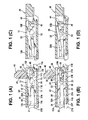
- Housing 30 having a rectangular section extends in a perpendicular direction with respect to a sheet surface.
- the housing 30 is formed of an insulative member and is provided with container grooves 31 and 32 to accommodate the terminals 10 and 20, respectively.
- the container grooves 31 and 32 have an inner width commensurate with a plate thickness of the terminals 10 and 20 (an inner width in a perpendicular direction with respect to the sheet surface) and are in a slit shape extending parallel to the sheet surface.
- connection portions 13 and 23 connect the fixed arm portions 11 and 21 and the movable arm portions 12 and 22 in an intermediate portion of a longitudinal direction thereof so as to form each of the fixed arm portions 11 and 21 and the movable arm portions 12 and 22 to be a member of the connector.
- the terminal 10 is inserted into the container groove 31 of the housing 30 from a right edge side thereof.
- the fixed arm portion 11 is accommodated to the container groove 31 on the lower wall 35 side of the housing 30, and the movable arm portion 12 is accommodated to the container groove 31 on the upper wall 36 side of the housing 30.
- the fixed arm portion 11 is adjacent to a lower edge of the container groove 31.
- the engagement protrusion 11E of the fixed arm portion 11 is buried in the fixed portion 37 of the housing 30. A reaction force from the fixed portion 37 presses the lower edge of the fixed arm portion 11 hard to fix to an upper surface of the lower wall 35 of the housing 30.
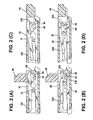
- the joining portion 23 of the terminal 20 is situated more right side of the joining portion 13 of the terminal 10. Accordingly, a ratio of a distance from the joining portion 23 to the press portion 22A and a distance from the joining portion 23 to the pressed portion 22B in the terminal 20 is the same or substantially the same as a ratio of a distance form the joining portion 13 to the press portion 12A and a distance from the joining portion 13 and the pressed portion 12B in the terminal 10.
- the press portions are displaced according to the ratio. Accordingly, the displacement amounts at the press portions 12A and 22A of the terminals 10 and 20 are to be the same.
Landscapes
- Coupling Device And Connection With Printed Circuit (AREA)
Applications Claiming Priority (1)
| Application Number | Priority Date | Filing Date | Title |
|---|---|---|---|
| JP2006309005A JP4282027B2 (ja) | 2006-11-15 | 2006-11-15 | 平型導体用電気コネクタ |
Publications (1)
| Publication Number | Publication Date |
|---|---|
| EP1923959A1 true EP1923959A1 (de) | 2008-05-21 |
Family
ID=38920715
Family Applications (1)
| Application Number | Title | Priority Date | Filing Date |
|---|---|---|---|
| EP07022090A Withdrawn EP1923959A1 (de) | 2006-11-15 | 2007-11-14 | Elektrischer Steckverbinder für Flachleiter |
Country Status (6)
| Country | Link |
|---|---|
| US (1) | US7467962B2 (de) |
| EP (1) | EP1923959A1 (de) |
| JP (1) | JP4282027B2 (de) |
| KR (1) | KR101018615B1 (de) |
| CN (1) | CN101202387B (de) |
| TW (1) | TW200822473A (de) |
Families Citing this family (18)
| Publication number | Priority date | Publication date | Assignee | Title |
|---|---|---|---|---|
| JP5070884B2 (ja) * | 2007-03-06 | 2012-11-14 | 第一精工株式会社 | 電気コネクタ |
| US7527511B1 (en) * | 2008-05-09 | 2009-05-05 | Cheng Uei Precision Industry Co., Ltd. | Connector for flexible printed circuit board |
| JP4878615B2 (ja) * | 2008-09-11 | 2012-02-15 | ヒロセ電機株式会社 | 平型導体用電気コネクタ |
| TWM354923U (en) * | 2008-11-21 | 2009-04-11 | Taiwan Suncagey Ind Co Ltd | Improved electrical connector for back-lift flexible circuit board |
| JP5344285B2 (ja) * | 2008-12-02 | 2013-11-20 | 第一精工株式会社 | コネクタ装置 |
| JP4989741B2 (ja) * | 2010-02-26 | 2012-08-01 | ヒロセ電機株式会社 | 回路基板用電気コネクタ |
| JP4989740B2 (ja) * | 2010-02-26 | 2012-08-01 | ヒロセ電機株式会社 | 回路基板用電気コネクタ |
| JP4951085B2 (ja) * | 2010-04-08 | 2012-06-13 | パナソニック株式会社 | コネクタ |
| JP5121884B2 (ja) * | 2010-05-31 | 2013-01-16 | ヒロセ電機株式会社 | 平型導体用電気コネクタ |
| JP5630365B2 (ja) * | 2011-04-13 | 2014-11-26 | オムロン株式会社 | コネクタ用接続端子およびそれを用いたコネクタ |
| JP5621999B2 (ja) * | 2012-03-09 | 2014-11-12 | 第一精工株式会社 | コネクタ装置 |
| JP5862387B2 (ja) * | 2012-03-15 | 2016-02-16 | オムロン株式会社 | コネクタ |
| JP5392929B2 (ja) * | 2012-06-11 | 2014-01-22 | 日本航空電子工業株式会社 | コネクタ |
| JP6342342B2 (ja) * | 2015-01-26 | 2018-06-13 | 日本航空電子工業株式会社 | コネクタ |
| JP6356167B2 (ja) * | 2016-02-10 | 2018-07-11 | 株式会社フジクラ | コネクタ |
| JP7033727B2 (ja) * | 2017-08-09 | 2022-03-11 | パナソニックIpマネジメント株式会社 | コネクタ |
| KR102543054B1 (ko) * | 2017-12-27 | 2023-06-14 | 엘지디스플레이 주식회사 | 케이블, 컨넥터, 그를 이용한 인쇄회로기판 및 표시장치 |
| TWI824285B (zh) * | 2021-08-27 | 2023-12-01 | 唐虞企業股份有限公司 | 電連接器 |
Citations (3)
| Publication number | Priority date | Publication date | Assignee | Title |
|---|---|---|---|---|
| US20060205257A1 (en) * | 2002-08-01 | 2006-09-14 | Masayuki Suzuki | Connector |
| JP2006252844A (ja) * | 2005-03-09 | 2006-09-21 | Kyocera Elco Corp | コネクタ |
| JP2006309005A (ja) | 2005-04-28 | 2006-11-09 | Canon Inc | 光学機器 |
Family Cites Families (5)
| Publication number | Priority date | Publication date | Assignee | Title |
|---|---|---|---|---|
| JP2004178959A (ja) | 2002-11-27 | 2004-06-24 | D D K Ltd | コネクタ |
| JP4073766B2 (ja) | 2002-11-27 | 2008-04-09 | 第一電子工業株式会社 | コネクタ |
| CN2596583Y (zh) * | 2003-02-19 | 2003-12-31 | 禾昌兴业股份有限公司 | 端子结构改良 |
| JP4223323B2 (ja) | 2003-05-14 | 2009-02-12 | 京セラエルコ株式会社 | コネクタ |
| JP4484219B2 (ja) * | 2005-06-20 | 2010-06-16 | 第一電子工業株式会社 | コネクタ |
-
2006
- 2006-11-15 JP JP2006309005A patent/JP4282027B2/ja active Active
-
2007
- 2007-10-29 TW TW096140596A patent/TW200822473A/zh unknown
- 2007-11-08 CN CN2007101669874A patent/CN101202387B/zh active Active
- 2007-11-08 US US11/979,771 patent/US7467962B2/en not_active Expired - Fee Related
- 2007-11-14 EP EP07022090A patent/EP1923959A1/de not_active Withdrawn
- 2007-11-15 KR KR1020070116760A patent/KR101018615B1/ko active IP Right Grant
Patent Citations (3)
| Publication number | Priority date | Publication date | Assignee | Title |
|---|---|---|---|---|
| US20060205257A1 (en) * | 2002-08-01 | 2006-09-14 | Masayuki Suzuki | Connector |
| JP2006252844A (ja) * | 2005-03-09 | 2006-09-21 | Kyocera Elco Corp | コネクタ |
| JP2006309005A (ja) | 2005-04-28 | 2006-11-09 | Canon Inc | 光学機器 |
Also Published As
| Publication number | Publication date |
|---|---|
| CN101202387B (zh) | 2011-07-13 |
| JP4282027B2 (ja) | 2009-06-17 |
| KR20080044196A (ko) | 2008-05-20 |
| JP2008123946A (ja) | 2008-05-29 |
| TW200822473A (en) | 2008-05-16 |
| TWI356543B (de) | 2012-01-11 |
| US20080113542A1 (en) | 2008-05-15 |
| US7467962B2 (en) | 2008-12-23 |
| CN101202387A (zh) | 2008-06-18 |
| KR101018615B1 (ko) | 2011-03-03 |
Similar Documents
| Publication | Publication Date | Title |
|---|---|---|
| EP1923959A1 (de) | Elektrischer Steckverbinder für Flachleiter | |
| US7530831B2 (en) | Electrical connector | |
| JP4330084B2 (ja) | 平型導体用電気コネクタ | |
| EP1244179B1 (de) | Elektrischer Verbinder für Flachkabel | |
| CN101228674B (zh) | 连接器 | |
| US9853382B2 (en) | Connector | |
| US9735503B2 (en) | Connector for receiving and electrically connecting with a cable | |
| EP2211424A1 (de) | Elektrischer Steckverbinder | |
| US20140162492A1 (en) | Connector, connector assembly, and cable for use in the connector assembly | |
| US9172190B2 (en) | Connector | |
| US9281593B2 (en) | Connector which is reduced in possibility of damage due to warping of a connection object without decreasing the insertability of the connection object | |
| JP4775917B2 (ja) | 平型導体用電気コネクタ | |
| JP2016035929A (ja) | コネクタ |
Legal Events
| Date | Code | Title | Description |
|---|---|---|---|
| PUAI | Public reference made under article 153(3) epc to a published international application that has entered the european phase |
Free format text: ORIGINAL CODE: 0009012 |
|
| AK | Designated contracting states |
Kind code of ref document: A1 Designated state(s): AT BE BG CH CY CZ DE DK EE ES FI FR GB GR HU IE IS IT LI LT LU LV MC MT NL PL PT RO SE SI SK TR |
|
| AX | Request for extension of the european patent |
Extension state: AL BA HR MK RS |
|
| 17P | Request for examination filed |
Effective date: 20081120 |
|
| 17Q | First examination report despatched |
Effective date: 20081230 |
|
| AKX | Designation fees paid |
Designated state(s): DE FR GB IT |
|
| STAA | Information on the status of an ep patent application or granted ep patent |
Free format text: STATUS: THE APPLICATION IS DEEMED TO BE WITHDRAWN |
|
| 18D | Application deemed to be withdrawn |
Effective date: 20120530 |