EP1923902B1 - Magnetron sputtering source, sputter coating system and method for coating a substrate - Google Patents
Magnetron sputtering source, sputter coating system and method for coating a substrate Download PDFInfo
- Publication number
- EP1923902B1 EP1923902B1 EP06124060A EP06124060A EP1923902B1 EP 1923902 B1 EP1923902 B1 EP 1923902B1 EP 06124060 A EP06124060 A EP 06124060A EP 06124060 A EP06124060 A EP 06124060A EP 1923902 B1 EP1923902 B1 EP 1923902B1
- Authority
- EP
- European Patent Office
- Prior art keywords
- target
- plasma
- coating
- sputtering source
- magnetron sputtering
- Prior art date
- Legal status (The legal status is an assumption and is not a legal conclusion. Google has not performed a legal analysis and makes no representation as to the accuracy of the status listed.)
- Not-in-force
Links
Images


Classifications
-
- H—ELECTRICITY
- H01—ELECTRIC ELEMENTS
- H01J—ELECTRIC DISCHARGE TUBES OR DISCHARGE LAMPS
- H01J37/00—Discharge tubes with provision for introducing objects or material to be exposed to the discharge, e.g. for the purpose of examination or processing thereof
- H01J37/32—Gas-filled discharge tubes
- H01J37/34—Gas-filled discharge tubes operating with cathodic sputtering
- H01J37/3402—Gas-filled discharge tubes operating with cathodic sputtering using supplementary magnetic fields
- H01J37/3405—Magnetron sputtering
- H01J37/3408—Planar magnetron sputtering
-
- C—CHEMISTRY; METALLURGY
- C23—COATING METALLIC MATERIAL; COATING MATERIAL WITH METALLIC MATERIAL; CHEMICAL SURFACE TREATMENT; DIFFUSION TREATMENT OF METALLIC MATERIAL; COATING BY VACUUM EVAPORATION, BY SPUTTERING, BY ION IMPLANTATION OR BY CHEMICAL VAPOUR DEPOSITION, IN GENERAL; INHIBITING CORROSION OF METALLIC MATERIAL OR INCRUSTATION IN GENERAL
- C23C—COATING METALLIC MATERIAL; COATING MATERIAL WITH METALLIC MATERIAL; SURFACE TREATMENT OF METALLIC MATERIAL BY DIFFUSION INTO THE SURFACE, BY CHEMICAL CONVERSION OR SUBSTITUTION; COATING BY VACUUM EVAPORATION, BY SPUTTERING, BY ION IMPLANTATION OR BY CHEMICAL VAPOUR DEPOSITION, IN GENERAL
- C23C14/00—Coating by vacuum evaporation, by sputtering or by ion implantation of the coating forming material
- C23C14/22—Coating by vacuum evaporation, by sputtering or by ion implantation of the coating forming material characterised by the process of coating
- C23C14/34—Sputtering
- C23C14/3407—Cathode assembly for sputtering apparatus, e.g. Target
-
- C—CHEMISTRY; METALLURGY
- C23—COATING METALLIC MATERIAL; COATING MATERIAL WITH METALLIC MATERIAL; CHEMICAL SURFACE TREATMENT; DIFFUSION TREATMENT OF METALLIC MATERIAL; COATING BY VACUUM EVAPORATION, BY SPUTTERING, BY ION IMPLANTATION OR BY CHEMICAL VAPOUR DEPOSITION, IN GENERAL; INHIBITING CORROSION OF METALLIC MATERIAL OR INCRUSTATION IN GENERAL
- C23C—COATING METALLIC MATERIAL; COATING MATERIAL WITH METALLIC MATERIAL; SURFACE TREATMENT OF METALLIC MATERIAL BY DIFFUSION INTO THE SURFACE, BY CHEMICAL CONVERSION OR SUBSTITUTION; COATING BY VACUUM EVAPORATION, BY SPUTTERING, BY ION IMPLANTATION OR BY CHEMICAL VAPOUR DEPOSITION, IN GENERAL
- C23C14/00—Coating by vacuum evaporation, by sputtering or by ion implantation of the coating forming material
- C23C14/22—Coating by vacuum evaporation, by sputtering or by ion implantation of the coating forming material characterised by the process of coating
- C23C14/34—Sputtering
- C23C14/3485—Sputtering using pulsed power to the target
-
- C—CHEMISTRY; METALLURGY
- C23—COATING METALLIC MATERIAL; COATING MATERIAL WITH METALLIC MATERIAL; CHEMICAL SURFACE TREATMENT; DIFFUSION TREATMENT OF METALLIC MATERIAL; COATING BY VACUUM EVAPORATION, BY SPUTTERING, BY ION IMPLANTATION OR BY CHEMICAL VAPOUR DEPOSITION, IN GENERAL; INHIBITING CORROSION OF METALLIC MATERIAL OR INCRUSTATION IN GENERAL
- C23C—COATING METALLIC MATERIAL; COATING MATERIAL WITH METALLIC MATERIAL; SURFACE TREATMENT OF METALLIC MATERIAL BY DIFFUSION INTO THE SURFACE, BY CHEMICAL CONVERSION OR SUBSTITUTION; COATING BY VACUUM EVAPORATION, BY SPUTTERING, BY ION IMPLANTATION OR BY CHEMICAL VAPOUR DEPOSITION, IN GENERAL
- C23C14/00—Coating by vacuum evaporation, by sputtering or by ion implantation of the coating forming material
- C23C14/22—Coating by vacuum evaporation, by sputtering or by ion implantation of the coating forming material characterised by the process of coating
- C23C14/34—Sputtering
- C23C14/35—Sputtering by application of a magnetic field, e.g. magnetron sputtering
-
- H—ELECTRICITY
- H01—ELECTRIC ELEMENTS
- H01J—ELECTRIC DISCHARGE TUBES OR DISCHARGE LAMPS
- H01J37/00—Discharge tubes with provision for introducing objects or material to be exposed to the discharge, e.g. for the purpose of examination or processing thereof
- H01J37/32—Gas-filled discharge tubes
- H01J37/34—Gas-filled discharge tubes operating with cathodic sputtering
- H01J37/3411—Constructional aspects of the reactor
- H01J37/3414—Targets
- H01J37/3423—Shape
-
- H—ELECTRICITY
- H01—ELECTRIC ELEMENTS
- H01J—ELECTRIC DISCHARGE TUBES OR DISCHARGE LAMPS
- H01J37/00—Discharge tubes with provision for introducing objects or material to be exposed to the discharge, e.g. for the purpose of examination or processing thereof
- H01J37/32—Gas-filled discharge tubes
- H01J37/34—Gas-filled discharge tubes operating with cathodic sputtering
- H01J37/3411—Constructional aspects of the reactor
- H01J37/345—Magnet arrangements in particular for cathodic sputtering apparatus
- H01J37/3455—Movable magnets
Definitions
- Sputtering or (cathode) sputtering is a commonly used technology for producing thin films on substrates.
- a target is bombarded with ions, such as inert gas ions from an ignited plasma.
- ions such as inert gas ions from an ignited plasma.
- the material which is intended directly or indirectly for coating is sputtered from the target, that is to say released or atomized.
- the sputtered material is deposited, possibly after a chemical reaction, on the substrate opposite the target.
- the substrate may be either stationary relative to the target during the coating process, or continuously transported past the target.
- a magnetron sputter source has a magnet arrangement, which is arranged on the side of the target facing away from the substrate.
- the magnet system generates a magnetic field and influences the coating plasma, which forms on the substrate side in an area above the target surface.
- an inhomogeneous plasma structure forms over the surface of the target, which leads to a non-uniform erosion of the target material.
- Magnetic arrangements are typically used which generate plasma channels in closed form, for example in the form of an elongated oval (race track).
- the inhomogeneity of the plasma leads to the formation of erosion ditches in the target.
- the target material can not be completely used up, on the other hand lead the Inhomogeneous erosion and the formation of erosion ditches to a non-homogeneous and uniform coating of the substrate.
- a cooling device can only reduce the temperature of the uppermost atomic layers of the target limited.
- the maximum possible power density is limited by the occurrence of arcing at power densities higher than about 3 W / cm 2 .
- the publication US 2005/061661 A1 shows a movable magnetron sputter coating machine.
- the aim of this invention is to achieve as homogeneous a target erosion as possible and to prevent arcing.
- the arcing is prevented by selecting a suitable method, namely by "arc-free DC reactive deposition" (as opposed to RF magnetron sputtering).
- the movement of the magnetron prevents inhomogeneous target erosion.
- the publication WO 01/77402 refers to the coating of the inside of tubular substrates, wherein a magnet set having a plurality of annular magnetic fields is moved in the axial direction through a target tube to deposit layer uniformity on the inner wall of the substrate.
- the publication EP 1 076 352 refers to a system that operates in self-sputtering mode, using a small, rotating magnet set and a relatively large substrate.
- the aim is a high degree of ionization of the sputtered metal to self-sputtering.
- magnetron sputtering sources according to claim 1, a sputter coating apparatus according to claim 15, and a method according to claim 16.
- the magnetron sputtering source according to the invention for a coating installation comprises at least one cathode and at least one cathode-assigned or cathode-forming target which provides coating and / or treatment material for coating and / or treatment, means for generating a coating plasma and at least one magnet arrangement Generation of a magnetic field for influencing the coating plasma such that at least over a partial area of the target at least one plasma channel is generated.
- the magnet arrangement and the surface of the target are arranged to be movable relative to one another by means of a drive.
- the drive is for generating a speed (v, v + u) of the relative movement between the magnet arrangement (7) and the surface (4 ') of the target (4) of at least 0.2 m / s for reducing the heat load on the target surface (4 ') and the exposure time of the plasma formed on the surface area.
- the exposure time is calculated as the quotient of the width of the plasma channel (the width in this context is the extension of the plasma channel along the direction of movement), which covers the surface area, and the scanning speed.
- the sputtering rate can be adapted to the exposure time, in particular so far increased that (despite high sputtering rate) no undesired surface effects occur.
- the area ratio between the total target area and the plasma channel must be so high that sufficient cooling of the surface takes place prior to the next scanning of said surface area.
- the exposure time of the plasma refers to a single movement of the plasma channel over the surface area of the target. The larger the area ratio between the entire target surface and the surface of the plasma channel or plasma channels, the greater are the "recovery times" for the surface areas of the target at a given velocity profile along the path of the plasma channel (and with a complete scanning of the surface) two consecutive scans / plasma effects.
- the present invention is based on the recognition that the thermal inertia of the surface of the target can be exploited in order to work with higher power densities and consequently higher sputtering rates.
- the power density corresponds to the power introduced into the system per cathode surface unit.
- the power density is functionally related to the sputtering rate.
- the plasma significantly shortens to a surface area of the target with movement of the plasma channel relatively over the surface area. Due to the shorter time period of the action of the plasma during an "overscan" of the surface area, power densities or sputtering rates can be shifted upward without significant undesirable surface effects on the target surface, such as, for example, As arcing, melting of the target, local outgassing of the target, chemical reactions of compounds in the target, etc., occur. As a result, the overall energy input into a surface area (with a certain unit area) can be increased over a given (short) period of time without surface effects on the target surface.
- the target can be "scanned" several times from the plasma channel, whereby the temperature of the uppermost atomic layers of the target increases significantly less than with a longer, albeit less powerful action of the plasma.
- a surface area is scanned several times during a coating cycle, it is preferably ensured that the time between the two exposure phases is sufficiently large for a cooling of the surface.
- the heating during scanning depends on the total energy supplied and on the sequence in which the energy is supplied. It has been recognized that more meaningful sequences of energy input are possible than a virtually constant supply of total energy with a low sputtering rate.
- the velocity profile is adjusted to the duration of the plasma over the target.
- the relative movement between the magnet arrangement and the surface of the target should be interpreted widely within the scope of the invention.
- the target or the cathode can move relative to the magnet arrangement.
- the magnet assembly may be movable relative to the target or to the cathode.
- both components, magnet assembly and cathode or target are arranged relative to each other and movable relative to the coating system.
- the magnet system is arranged on the side facing away from the substrate to be coated of the target to be atomized.
- the magnet arrangement in particular comprises one or more magnets, in particular permanent magnets, and at least one yoke.
- the magnet system can generate one or more plasma channels which are arranged side by side or in one another.
- plasma channels are race tracks (a substantially elongated, oval, closed track), a bone-shaped, closed path or a closed path similar to a rhombus in question.
- the invention is suitable for all common sputtering processes, for example for sputtering with inert gas (argon, etc.), sputtering with reactive gas (oxygen, nitrogen, NH 3 , etc.)
- reactive gas oxygen, nitrogen, NH 3 , etc.
- target materials can be used. These may be, for example, metals, metal alloys, or metal-nonmetal compounds such as ITO, IZO, ZnO: Al, SiO 2 , IGZO (InGaZnO).
- the thickness of the target can be increased at the two reversal points or reversal portions of the movement of the magnet system relative to the thickness of the material over the remaining target surface, since in the reversal regions due to the velocity profile naturally greater erosion occurs.
- This measure makes it possible to obtain a minimum and uniform Tartrestdicke over the entire target at the end of the target life, with the advantage of a correspondingly high target utilization.
- the perpendicular distance of the magnet system from the target rear side in the reversal regions can be increased and / or the power supply in the reversal regions can be reduced in order to prevent faster erosion in these regions compared to the remaining surface regions.
- better coating results are achieved when the reversal region lies in the edge region of the target, since higher Yields in this range are desirable for uniform coating.
- a surface area of the target in the sense of the claims is a small surface area of the surface of the target, in particular the partial area of the target covered by the plasma channel, compared to the entire area which the plasma channel acts on during the scanning.
- the surface area can be an infinitesimally small area, via which the influence or the effect of the plasma moving over the area is determined in any case.
- the advantages of the magnetron sputtering source according to the invention lie primarily in the possibility of using higher sputtering rates. Due to the higher sputtering rates, a coating system can be shortened with a constant cycle time, which leads to a reduction of the acquisition and operating costs. In addition, it has been shown that with the inventive concept large-area coatings, which are to be deposited statically (such as TFT coatings), can be realized with much more homogeneous layer thickness distributions than with conventional technologies that use several cathodes arranged in parallel.
- the drive is set such that during a coating cycle, a speed of the relative movement of at least 0.3 m / s, in particular 0.5 m / s, in particular of 1.0 m / s, in particular of 3 , 0 m / s, in particular of 5.0 m / s, is exceeded.
- suitable drives e.g. Belt drives or linear motors, the mentioned high speeds can be easily realized.
- Each surface area of the target surface is under the influence of the coating plasma during overscanning for a certain period of time, the time being inversely proportional to the relative velocity of movement between the plasma channel and the target surface. This means that by increasing the speed, a shortening of the exposure time of the plasma is achieved on the surface area. This in turn makes it possible to use higher sputtering rates during scanning.
- the magnet system can oscillate, for example, between the two parallel, in particular between the two shorter target edges. This oscillation can be superimposed by movements in the other spatial directions (ie not parallel to the central longitudinal axis of the target).
- the instantaneous velocity may be constant over the major part of the trajectory relative to the target surface. This constant velocity should at least reach the minimum velocity values stated in the claims. Alternatively, the instantaneous speed can also be variable to z. B. layer thickness distributions or target erosion profiles. It is clear that in the presence of inflection points and decelerations of the relative motion, the speed temporarily drops to lower values or to zero.
- the scanning speed should exceed the speed values mentioned in the claims over a larger part of the path over the target surface, preferably over 50% of the web length, particularly preferably over 75% of the web length, during a coating cycle.
- the high speed scanned area is even larger.
- the magnetron sputtering source is set such that the power density at least temporarily has a value of at least 5 W / cm 2 , in particular a value of at least 15 W / cm 2 , in particular a value of 30 W / cm 2 , in particular a value of 50 W / cm 2 , in particular a value of 75 W / cm 2 , achieved.
- the loading of the surface of the target by an increase in the sputtering rate is compensated by an increase in the scan (scanning) speed and thus the exposure time of the plasma to the surface area.
- the magnetron sputtering source according to the invention is designed or set for operation with such power densities.
- the adjustment of the relative velocity between the magnet assembly and the surface of the target is based on the ratio of the size of the total surface of the target to the surface of the plasma channel projected onto the target surface and the surface on the surface of the target to which the plasma has a significant effect , and depending on the desired sputtering rate.
- the maximum speed is set, so that an associated maximum sputtering rate, which is determined empirically, can be realized.
- the ratio of the total surface area of the target to the surface of the plasma channel is at least 15, in particular 30, in particular 45, in particular 90.
- Said area ratio is in conjunction with the other variables that can be matched, namely the velocity profile and the profile of the sputtering rate (over the path). , also important. This ratio determines the intervals at which a certain surface area of the target surface is under the influence of the plasma.
- the ratio of the total sputtering surface of the target to the surface of the plasma channel or the plasma channels must be chosen sufficiently large that each surface area can cool sufficiently before the next scan. Since the largest possible area ratio ensures good cooling, the process is particularly suitable for large-area coatings with large-area targets.
- a sufficiently high speed combined with high sputtering rates can be realized.
- the area ratio indirectly determines the maximum possible sputtering rate via the adjustable speed.
- the sputtering source is preferably set such that the total exposure time of the plasma to a specific surface area of the target per coating cycle is subdivided into at least two temporally separate periods of time.
- the coating cycle is considered to be a cycle for coating a substrate with the intended coating carried out in the station.
- a coating cycle however, a time-closed coating process can be considered in which several substrates are coated directly one behind the other.
- each surface area of the target is short-flashed by the high scanning speed and two or more times during a coating cycle under the influence of the plasma.
- the thermal inertia of the target material is utilized, which does not overheat during the short scan duration and sufficiently cools down through a suitable area ratio (as described above) between two scan cycles.
- the target is preferably rectangular with a length and a width wherein preferably the length is a multiple of the width, and the magnet arrangement and the target are arranged to be movable relative to one another at least along the direction of the length of the target.
- This movement can be superimposed by movements in other spatial directions.
- an oscillating relative movement can be performed between the two transverse edges.
- the target may be formed with a substantially flat and / or curved surface.
- the target may be mounted on a cooled backplate, such as by bonding, claws, screws, spraying, etc.
- the target may be formed either as a planar cathode or as a domed cathode, for example 2.5m x 0.3m in size.
- the target may also be formed as a surface cathode or as a curved surface cathode, for example, with a size of 2, 5 m x 2 m.
- the magnetron sputtering source may also be a rotatable magnetron tube sputtering source having a tube cathode and / or a rotatable tube target.
- the relative speed between the target and the magnet system corresponds here to the path velocity of the target surface relative to the magnet system.
- the area ratio between the total surface area of the target and the area of the plasma channel can be achieved inter alia by increasing the target diameter.
- the principle of the invention should refer to all possible rotatable cathodes / targets where the description specifies planar targets.
- At least one anode or anode arrangement is provided for receiving electrons to be dissipated.
- the anode may be formed by the surroundings of the magnetron cathode, for example the chamber wall, a dark space frame, a circumferential profile, etc.
- the anode or anode arrangement may in particular also comprise at least one electrode which, relative to the target, over the Target surface is arranged movable.
- the electrode will usually move in synchronism with the magnet system relative to the target.
- the electrode may be arranged along a plasma channel.
- the anode or anode assembly may include a plurality of electrodes disposed immovable or fixed relative to the target over the target surface.
- one or more cooled or uncooled bars can be used as anodes along the direction of movement of the Magnet system in front of the target or the Tartrand and / or parallel to the magnet system in front of the target.
- the electrodes act punctually in the plasma channel and are electrically connected in synchronism with the movement of the magnet system.
- the target may preferably consist of one or more segments which are galvanically coupled or separated. If the target is divided into mutually decoupled segments, means may be provided which shell at least one segment as a cathode, while at least one adjacent segment is connected as an anode.
- the electrical potential of the individual target segments can be synchronized with the movement of the magnet system, i. the target segments can be electrically switched in synchronism with the movement of the magnet system. For example, the negative sputtering potential is only applied to that target segment which is traversed by the magnet system at the given time. The remaining target segments are not at sputtering potential but, for example, at ground, at positive or floating potential.
- the means for generating a coating plasma may include a power supply device comprising an AC, a DC, a unipolar pulsed, a bipolar pulsed, or an RF (radio frequency) source. From this source, the power is coupled into the system.
- a power supply device comprising an AC, a DC, a unipolar pulsed, a bipolar pulsed, or an RF (radio frequency) source. From this source, the power is coupled into the system.
- the object according to the invention is also achieved by a sputter-coating installation comprising at least one treatment space and a magnetron sputtering source as described above.
- the plasma channel is guided at high speed (relatively) over a surface area of the target, so that a period of time in which the plasma continuously acts on the surface area is shortened such that even at high power density (and thus high sputtering rate) no significant undesirable surface effects occur at the target surface.
- the relative velocity of the plasma channel with respect to the surface of the target exceeds a value of 0.3 m / s, in particular of 0.5 m / s, in particular of 1.0 m / s, in particular of 3.0 m / s, in particular of 5.0 m / s.
- the plasma channel has an oval, a long oval, a bony or a rhomboid shape.
- the power density at least temporarily preferably reaches a value of at least 5 W / cm 2 , in particular a value of at least 15 W / cm 2 , in particular a value of 30, W / cm 2 , in particular a value of 50 W / cm 2 , in particular a value of 75 W / cm 2 .
- the magnetron sputtering source according to the invention is designed or set for operation with such power densities.
- the magnetic field influences the plasma to form at least one plasma channel, in particular in an oval shape (race track), a bone-like shape and / or in the form of a rhombus.
- a ratio of the total sputtering surface of the target to the surface of the target projected plasma channel surface exceeds a value of 15, in particular of 30, in particular 45, in particular of 90. Is the plasma channel generated in step c) relative to Area of the target small area, the time intervals between which a surface area of the target surface is scanned, relatively large.
- the target is rectangular in length and width, the length being a multiple of the width, and the magnetic field moving at least along the direction of the length of the target relative to the target.
- the magnetic field may oscillate relative to the edges of the target.
- the total exposure time of the plasma to a specific surface area of the target surface can be subdivided per coating cycle into at least two temporally separate periods of time.
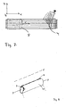
- FIG. 1 A sectional view of a coating system according to the invention
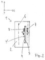
- FIG. 2 A side sectional view of a coating system according to the invention
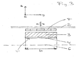
- FIG. 3 A sectional view of a magnetron sputtering source according to the invention
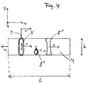
- FIG. 4 A plan view of a section of a sputtering source according to the invention during operation
- FIG. 5 A side view of a section of a sputtering source according to the invention during operation
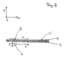
- FIG. 6 A side view of a section of another sputtering source according to the invention during operation
- FIG. 7 A plan view of a sputtering source according to the invention.
- FIG. 8 A rotatable cathode within the scope of the invention.
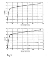
- FIG. 9 A diagram that outlines the relationship between the set speed and the power density.
- FIG. 1 shows a coating system 1 according to the invention in a sectional view.
- an elongated cathode 3 is arranged with a length I and a width b, on which a target 4 is mounted.
- the cathode 3 lies in this view below the target 4 in the leaf level.
- cathode 3 and target 4 can also be embodied as an integrated component, ie the target material 4 can itself form the cathode 3.
- the cathode 3 is connected via a connecting line with the power supply 5.
- the electrical power can be coupled into the coating system 1 as direct current, alternating current, unipolar pulsed current, bipolar pulsed current or radio frequency (RF) voltage.
- RF radio frequency
- FIG. 2 shows, as the coordinate system indicates at the top left, a lateral section of the coating system 1.
- a coating chamber 2 which is delimited by walls, a cathode 3 and the attached to the cathode 3 target material 4 are arranged.
- the target material 4 is facing a substrate plane 6, in which the substrates lie during the coating or along which the substrates are transported.
- the substrate plane 6 extends substantially parallel the target 4 with the underlying cathode 3.
- the target itself can form the cathode.
- the target 4 must always be at cathode potential.
- a magnet system 7 (for example consisting of yoke and magnet, not shown in detail) moves along the longitudinal direction of the cathode 3 or the target 4 at high speed, for example 1 m / s , The target 4 is scanned at high relative velocity v along the longitudinal extent I of the target 4.
- the magnet system can be driven on a carrier by a drive (not shown).
- the magnet system 7 is designed such that it generates a circumferential oval plasma channel 8 (race track) at a distance above the target surface.
- the plasma channel moves over the surface of the target 4 at the same speed v as the magnet system 7.
- the direction of movement is indicated by the arrow v.
- the high scanning speed prevents locally such a strong heating of the surface 4 'of the target 4 that can lead to surface effects such as melting of the target 4, local outgassing or chemical transformations of the compounds in the target 4.
- an arcing temperature-induced arc discharge
- a magnetron sputtering source according to the invention is in FIG. 3 shown.
- the surface 4 'of the target 4 points towards the substrate plane 6, the magnet system 7 faces away from the substrate plane.
- the target 4 may be cooled under certain circumstances.
- the magnet system 7 moves primarily at high speed in a direction perpendicular to the sheet plane (x-direction) relative to the target 4. However, superimposed movements in the y and z directions are also possible.
- a relative movement of the magnet system 7 to the target 4 means that either the magnetic field, for example, oscillates between the parallel shorter target edges in the x-direction.
- the target 4 can be driven relative to the magnet system 7 while the magnet system is firmly positioned in the coating chamber 2.
- An opposite movement of the magnet system 7 to the target 4 would be conceivable. In this case, for example, the target 4 could perform a rapid movement in the x-direction, while the magnet system 7 undergoes a superimposed movement in the y- and / or z-direction.
- FIG. 4 shows a plan view of a target 4 of a sputtering source according to the invention.
- movable magnets or magnet arrangements are arranged in the x-direction. These move at a speed as illustrated by arrows v, or a given velocity profile along a scan path.
- the arrow u indicates a superimposed counter-movement of the target 4, so that altogether in the x-direction a relative velocity u + v results.
- the magnets or magnet systems form plasma channels 8, 8 ', 8 "vertically above the target surface 4'. These plasma channels 8, 8 ', 8" move together with the magnet systems in the x direction at the velocities u + v relative to the target 4.
- the plasma channels 8, 8 'and 8 “have, for example, different closed configurations, eg an elongated oval (race track 8), a diamond-like shape 8', which does not extend over the entire width b of the target 4, and a bone-shaped surface 8". (each projected onto the target surface 4 ').
- the areas of the plasma channels 8, 8 'and 8 “are small compared to the entire scanned target surface 4' (both individually and the sum of the areas 8, 8 ', 8").
- an area ratio between the area of the target 4 and the area (s) of the plasma channel (s) 8 or 8 'and 8 is set much larger than 5.
- high relative velocities u + v in the x direction between the Magnetic system 7 and the target 4 for example, relative velocities greater than 1 m / s
- the high relative velocity u + v combined with the large area ratio, the temperature in the top atomic layers of the target 4 over conventional arrangements
- the better cooling makes it possible to use significantly higher power densities or sputtering rates without interfering surface effects, such as, for example, melting of the target or arcing.
- FIG. 4 is also exemplified at the plasma channel 8 an anode 9 shown, which runs in the area of the race track.
- the anode 9 moves, synchronously with the underlying under the cathode magnet system and thus with the plasma channel 8 at an absolute velocity v, that is, with a relative velocity u + v, over the target surface 4 '.
- Superposed to the target 4 and / or the magnet system can perform a relative movement in the y- and / or z-direction, so that a specific erosion profile is set specifically.
- FIG. 5 shows the FIG. 5 in a side sectional view.
- a cathode 3 is provided with target material 4, wherein the target surface 4 'is aligned with the substrate plane 6.
- the magnet system 7 which is movable at a speed v along the x-axis (as indicated at the top left in the figure). With the magnet system, the plasma channel or race track 8 also moves at a distance above the surface of the target 4. Of course, a multiplicity of further plasma channels can be moved in the region above the target surface 4 'in addition to the plasma channel 8 by a corresponding design of the magnet system 7. be formed.
- the plasma channel 8 extends in the projection over a region d along an entire region D of the target 4 (D corresponds here to the length I of the target).
- the area ratio between the total target surface and the surface of the plasma channel 8 (projected onto the surface of the target 4) is at least 15. This can also apply in particular to the ratio D / d.
- the area of the plasma channel can also be roughly equated with the area of the magnetic yoke, since these sizes are dimensioned substantially similar.
- one or more plasma channels (race tracks) 8 can be generated in an area above the target 4 between the target 4 and the substrate plane 6, which can be arranged next to or inside each other in the form of a pattern.
- the magnet arrangement 7 can be specifically designed such that a specific layer distribution and the erosion profile of the target 4 be optimized.
- an immovable with respect to the target 4 arranged anode assembly 9 is shown.
- the anode assembly 9 can in principle be formed either by the surroundings of the magnetron cathode 3 (for example, the chamber wall, a dark space frame, a circumferential profile, etc.). I'm in the FIG. 5
- the anode assembly 9 consists of a plurality of adjacent bars, which may be cooled or uncooled. These act punctually in the plasma channel 8 and are electrically connected with the movement of the magnet system 7.
- one or two electrodes 9 could be provided which move together with the magnet system 7 and are arranged along a plasma channel.
- a drive 10 for the magnet system 7 may be provided by a control device 11 for controlling the scan speed and / or the scan path and / or the power density (and thus the sputtering rate).
- the controller 11 may control the sputtering rate depending on, for example, the speed and / or location coordinates of the magnet system.
- FIG. 6 shows a further embodiment of the invention, wherein like elements are designated by the previously used reference numerals.
- the cathode 3 and the target 4 are segmented.
- the respective target segments in the region of the plasma channel 8 are at cathode potential, while the adjacent corresponding target segments act as the anode.
- the segments are indexed in this embodiment, together with the movement of the magnet system 7 and the plasma channel 8, corresponding to a speed v.
- the distance between the segments preferably corresponds to the dark space distance to electrical flashovers between adjacent Segments that are at different potential to avoid.
- the hint of the proportions in the FIG. 6 is purely schematic.
- the invention for a number of common sputtering processes can be used, for example, for sputtering with inert gas (argon, etc.), but also for sputtering processes with reactive gases (oxygen, nitrogen, NH 3 , etc.).
- inert gas argon, etc.
- reactive gases oxygen, nitrogen, NH 3 , etc.
- FIG. 7 a further sputtering source according to the invention is disclosed, which differs from the previous embodiments by an anode arrangement, which are arranged parallel to the direction of movement v of the magnet system 7 and the plasma channel 8.
- FIG. 8 shows a rotatable cathode within the scope of the invention.
- the increased relative velocity is characterized as the web velocity v on the surface of the target.
- the scanned target length corresponds here to the circumference.
- Cathode / target 3, 4 rotate about a central axis A.
- the racetrack 8 above the magnet system 7 is indicated in dashed lines.
- FIG. 9 shows a diagram (in two versions without or with measuring points) showing the dependence between the set speed and the maximum possible power density, ie the power density that can be supplied before the target surface melts before arcing occurs or before chemical changes within Enter the target surface, illustrated.
- a sharp increase in the possible power density is already evident at speeds of 0.1 m / s.
- the curve continues to increase at higher relative speeds, but at a lower slope (starting at between about 0.3 m / s and 0.4 m / s). Nevertheless, even in the higher speed ranges, an increase in speed still leads to significant increases in power density.
Landscapes
- Chemical & Material Sciences (AREA)
- Engineering & Computer Science (AREA)
- Physics & Mathematics (AREA)
- Plasma & Fusion (AREA)
- Analytical Chemistry (AREA)
- Chemical Kinetics & Catalysis (AREA)
- Materials Engineering (AREA)
- Mechanical Engineering (AREA)
- Metallurgy (AREA)
- Organic Chemistry (AREA)
- Physical Vapour Deposition (AREA)
Abstract
Description
Die Erfindung betrifft eine Magnetron-Sputterquelle für eine Beschichtungsanlage, umfassend wenigstens eine Kathode und wenigstens ein der Kathode zugeordnetes oder in der Kathode integriertes Target, welches Beschichtungs- und/oder Behandlungsmaterial zur Beschichtung und/oder zur Behandlung bereitstellt, Mittel zur Erzeugung eines Beschichtungsplasmas, wenigstens eine Magnetanordnung zur Erzeugung eines Magnetfelds zur Beeinflussung des Beschichtungsplasmas derart, dass wenigstens über einer Teilfläche des Targets wenigstens ein Plasmakanal erzeugt wird, wobei die Magnetanordnung und das Target, vorzugsweise mittels wenigstens eines Antriebs, relativ zueinander bewegbar angeordnet sind. Darüber hinaus betrifft die Erfindung eine Sputter-Beschichtungsanlage, umfassend wenigstens einen Behandlungs- bzw. Beschichtungsraum und eine Magnetron-Sputterquelle. Die Erfindung bezieht sich außerdem auf ein Verfahren zur Behandlung, insbesondere zur Beschichtung eines Substrats, umfassend die Schritte:
- a) Bereitstellung einer Behandlungs- bzw. Beschichtungsanlage mit einem Target;
- b) Erzeugung eines Beschichtungsplasmas;
- c) Erzeugung eines Magnetfelds zur Beeinflussung des Beschichtungsplasmas derart, dass wenigstens über eine Teilfläche des Targets wenigstens ein Plasmakanal erzeugt wird; und
- d) Erzeugung einer relativen Bewegung zwischen dem Magnetfeld und dem Target.
- a) providing a treatment or coating system with a target;
- b) generating a coating plasma;
- c) generating a magnetic field for influencing the coating plasma in such a way that at least one plasma channel is generated over at least a partial area of the target; and
- d) generating a relative movement between the magnetic field and the target.
Für die Beschichtung von Substraten bzw. von Substratoberflächen, insbesondere für die Beschichtung oder Behandlung großflächiger Substrate, sind unterschiedliche Verfahren bekannt. Die verwendeten Beschichtungsprozesse müssen geeignet sein, auch dünne Schichten mit großer Homogenität und Uniformität zu erzeugen. Darüber hinaus ist es im Sinn eines wirtschaftlichen Betriebs von Beschichtungsanlagen notwendig, die Anlagengröße zu reduzieren und einen hohen Durchsatz an Substraten zu erreichen, so dass Schichtsysteme zu akzeptablen Preisen angeboten werden können. Unter diesen Voraussetzungen werden große Anstrengungen unternommen, um hochqualitative Schichtsysteme, auch für großflächige Substrate, durch den Einsatz effizienter Beschichtungsmethoden zu realisieren.For the coating of substrates or substrate surfaces, in particular for the coating or treatment of large-area substrates, different methods are known. The coating processes used must be suitable, even with thin layers great homogeneity and uniformity. Moreover, in the interests of cost-effective operation of coating equipment, it is necessary to reduce equipment size and achieve a high throughput of substrates, so that coating systems can be offered at acceptable prices. Under these conditions, great efforts are being made to realize high-quality coating systems, even for large-area substrates, by using efficient coating methods.
Sputtern bzw. (Kathoden-)Zerstäubung ist eine häufig eingesetzte Technologie zur Herstellung dünner Filme auf Substraten. Bei Sputter-Verfahren wird ein Target mit Ionen, beispielsweise mit Inertgas-Ionen aus einem entzündeten Plasma, bombardiert. Dadurch wird das Material, welches direkt oder indirekt zur Beschichtung bestimmt ist, vom Target abgesputtert, das heißt freigesetzt bzw. atomisiert. Das abgesputterte Material wird, unter Umständen nach einer chemischen Reaktion, auf dem dem Target gegenüberliegenden Substrat abgeschieden. Das Substrat kann während des Beschichtungsprozesses entweder stationär relativ zum Target angeordnet sein, oder kontinuierlich am Target vorbei transportiert werden.Sputtering or (cathode) sputtering is a commonly used technology for producing thin films on substrates. In sputtering, a target is bombarded with ions, such as inert gas ions from an ignited plasma. As a result, the material which is intended directly or indirectly for coating is sputtered from the target, that is to say released or atomized. The sputtered material is deposited, possibly after a chemical reaction, on the substrate opposite the target. The substrate may be either stationary relative to the target during the coating process, or continuously transported past the target.
Um die Effizienz des Sputterprozesses zu erhöhen, werden sog. Magnetron-Sputterquellen eingesetzt. Eine Magnetron-Sputterquelle weist eine Magnetanordnung auf, die an der dem Substrat abgewandten Seite des Targets angeordnet ist. Das Magnetsystem erzeugt ein Magnetfeld und beeinflusst das Beschichtungsplasma, welches sich substratseitig in einem Bereich oberhalb der Targetoberfläche ausbildet. In Abhängigkeit vom Verlauf der Magnetfeldlinien bildet sich über der Oberfläche des Targets eine inhomogene Plasmastruktur aus, die zu einer nicht uniformen Erosion des Targetmaterials führt. Typischerweise werden Magnetanordnungen eingesetzt, die Plasmakanäle in geschlossener Form, beispielsweise in Form eines lang gestreckten Ovals (Race-Track) erzeugen. Die Inhomogenität des Plasmas führt zur Ausbildung von Erosionsgräben im Target. Dadurch kann zum einen das Targetmaterial nicht vollständig aufgebraucht werden, zum anderen führen die inhomogene Abtragung und die Ausbildung von Erosionsgräben zu einer nicht homogenen und uniformen Beschichtung des Substrats.In order to increase the efficiency of the sputtering process, so-called magnetron sputter sources are used. A magnetron sputter source has a magnet arrangement, which is arranged on the side of the target facing away from the substrate. The magnet system generates a magnetic field and influences the coating plasma, which forms on the substrate side in an area above the target surface. Depending on the course of the magnetic field lines, an inhomogeneous plasma structure forms over the surface of the target, which leads to a non-uniform erosion of the target material. Magnetic arrangements are typically used which generate plasma channels in closed form, for example in the form of an elongated oval (race track). The inhomogeneity of the plasma leads to the formation of erosion ditches in the target. As a result, on the one hand, the target material can not be completely used up, on the other hand lead the Inhomogeneous erosion and the formation of erosion ditches to a non-homogeneous and uniform coating of the substrate.
Um dem entgegenzuwirken, wurden mobile Magnetanordnungen vorgeschlagen, die die Plasmaverteilung über der Targetoberfläche zeitlich derart verändern, dass eine im Wesentlichen homogene Abtragung des Targetmaterials erzielt werden kann. Beispielsweise kann oszillierende Bewegung des Magnetfelds erzeugt werden, um die Erosionsgräben zu glätten.To counteract this, mobile magnet arrangements have been proposed which change the plasma distribution over the target surface in time such that a substantially homogeneous removal of the target material can be achieved. For example, oscillating movement of the magnetic field can be generated to smooth the erosion trenches.
Zusätzlich zum Erfordernis hoher Homogenität der Beschichtung und möglichst vollständiger Ausnutzung des Targetmaterials besteht das Erfordernis hoher Effizienz von Beschichtungsanlagen. Die Effizienz bekannter Sputteranlagen wird im Wesentlichen durch eine sich einstellende hohe Oberflächentemperatur des Targets in den Bereichen unterhalb der des Plasmakanäle begrenzt. Bei dem Versuch, die Sputterrate und damit die Sputterleistun:g zu erhöhen, steigt der Energieeintrag pro Flächeneinheit an. Dies führt zu Oberflächeneffekten, die unerwünschte Störungen des Sputterns zur Folge haben. Die Oberflächeneffekte können z. B. in einem Schmelzen des Targets, in einem lokalen Ausgasen des Targets und in chemischen Umwandlungen von Verbindungen im Targetmaterial bestehen. Die Folge dieser Effekte sind geschmolzene Targets und thermisch bedingtes Arcing (Bogenentladungen). Die naheliegendste Maßnahme zur Vermeidung der genannten Temperatureffekte besteht in einer Kühlung des Targets. Das Target kann entsprechend beilspielsweise an einer gekühlten Rückplatte befestigt sein.In addition to the requirement for high homogeneity of the coating and as complete as possible utilization of the target material, there is a need for high efficiency of coating equipment. The efficiency of known sputtering systems is essentially limited by a self-adjusting high surface temperature of the target in the areas below that of the plasma channels. In which An attempt to increase the sputtering rate and thus the sputtering power increases the energy input per unit area. This leads to surface effects that result in unwanted sputtering. The surface effects can z. Example, in a melting of the target, in a local outgassing of the target and in chemical transformations of compounds in the target material. The consequences of these effects are melted targets and thermally induced arcing (arc discharges). The most obvious measure to avoid the mentioned temperature effects consists in a cooling of the target. The target can be fastened correspondingly, for example, on a cooled backplate.
Jedoch kann auch eine Kühleinrichtung die Temperatur der obersten Atomlagen des Targets nur begrenzt reduzieren. Beispielsweise ist beim Sputtern, von ITO die maximal mögliche Leistungsdichte durch das Auftreten von Arcing bei höheren Leistungsdichten als ca. 3 W/cm2 begrenzt.However, a cooling device can only reduce the temperature of the uppermost atomic layers of the target limited. For example, in sputtering, by ITO, the maximum possible power density is limited by the occurrence of arcing at power densities higher than about 3 W / cm 2 .
Die Druckschrift
Die Druckschrift
Die Druckschrift
Die Druckschrift
Ausgehend davon ist es die Aufgabe der vorliegenden Erfindung, eine Magnetron-Sputterquelle, eine Sputter-Beschichtungsanlage und ein Verfahren zur Behandlung eines Substrats bereitzustellen, mittels derer durch Erhöhung der Leistungsdichte die Effizienz des Beschichtungsprozesses gesteigert werden kann.Based on this, it is the object of the present invention to provide a magnetron sputtering source, a sputter-coating apparatus and a method for treating a substrate, by means of which the efficiency of the coating process can be increased by increasing the power density.
Diese Aufgabe wird gelöst durch Magnetron-Sputterquellen nach dem Anspruch 1, eine Sputter-Beschichtungsanlage nach Anspruch 15, und ein Verfahren nach Anspruch 16.This object is achieved by magnetron sputtering sources according to
Demgemäß umfasst die erfindungsgemäße Magnetron-Sputterquelle für eine Beschichtungsanlage wenigstens eine Kathode und wenigstens ein der Kathode zugeordnetes oder als Kathode ausgebildtes Target, welches Beschichtungs- und/oder Behandlungsmaterial zur Beschichtung und/oder Behandlung bereitstellt, Mittel zur Erzeugung eines Beschichtungsplasmas und wenigstens eine Magnetanordnung zur Erzeugung eines Magnetfelds zur Beeinflussung des Beschichtungsplasmas derart, dass wenigstens über einer Teilfläche des Targets wenigstens ein Plasmakanal erzeugt wird. Die Magnetanordnung und die Oberfläche des Targets sind mittels eines Antriebs relativ zueinander bewegbar angeordnet.Accordingly, the magnetron sputtering source according to the invention for a coating installation comprises at least one cathode and at least one cathode-assigned or cathode-forming target which provides coating and / or treatment material for coating and / or treatment, means for generating a coating plasma and at least one magnet arrangement Generation of a magnetic field for influencing the coating plasma such that at least over a partial area of the target at least one plasma channel is generated. The magnet arrangement and the surface of the target are arranged to be movable relative to one another by means of a drive.
Der Antrieb ist zur Erzeugung einer Geschwindigkeit (v, v+u) der Relativbewegung zwischen der Magnetanordnung (7) und der Oberfläche (4') des Targets (4) von wenigstens 0,2 m/s zur Vermindeung der Wärmebelastung der Targetoberfläche (4') und der Einwirkungsdauer des Plasmas auf den Oberflächenbereich ausgebildet.The drive is for generating a speed (v, v + u) of the relative movement between the magnet arrangement (7) and the surface (4 ') of the target (4) of at least 0.2 m / s for reducing the heat load on the target surface (4 ') and the exposure time of the plasma formed on the surface area.
Die Einwirkungsdauer errechnet sich als Quotient aus der Breite des Plasmakanals (die Breite ist in diesem Zusammenhang die Ausdehnung des Plasmakanals entlang der Bewegungsrichtung), die den Flächenbereich überstreicht, und der Scangeschwindigkeit. Je kleiner die Fläche des Plasmakanals und je größer die Relativgeschwindigkeit ist, desto geringer ist die Einwirkungsdauer des Plasmakanals auf einen bestimmten Bereich der Targetoberfläche. Aus diesem Grund sorgt eine Kombination von kleinem Plasmakanalabschnitt und hoher Scangeschwindigkeit (z.B. größer als 0,1 m/s) für eine kurze Wirkungsdauer auf den Oberflächenbereich. Die Sputterrate kann an die Einwirkdauer angepasst, insbesondere so weit erhöht werden, dass trotz hoher Sputterrate (noch) keine unerwünschten Oberflächeneffekte auftreten. Außerdem muss das Flächenverhältnis zwischen Gesamttargetfläche und dem Plasmakanal so hoch sein, dass vor dem nächsten Abscannen dieses genannten Oberflächenbereichs eine ausreichende Abkühlung der Oberfläche stattfindet. Die Einwirkungsdauer des Plasmas bezieht sich auf eine einmalig Bewegung des Plasmakanals über den Oberflächenbereich des Targets. Je größer das Flächenverhältnis zwischen der gesamten Targetoberfläche und der Oberfläche des Plasmakanals bzw. der Plasmakanäle ist, desto größer sind bei vorgegebenem Geschwindigkeitsprofil entlang der Bahn des Plasmakanals (und bei einem vollständigen Abscannen der Oberfläche) auch die "Erholungszeiten" für die Oberflächenbereiche des Targets zwischen zwei aufeinander folgenden Scans/Plasmaeinwirkungen.The exposure time is calculated as the quotient of the width of the plasma channel (the width in this context is the extension of the plasma channel along the direction of movement), which covers the surface area, and the scanning speed. The smaller the area of the plasma channel and the greater the relative velocity, the lower the exposure time of the plasma channel to a specific area of the target surface. For this reason, a combination of small plasma channel section and high scanning speed (eg greater than 0.1 m / s) ensures a short duration of action on the surface area. The sputtering rate can be adapted to the exposure time, in particular so far increased that (despite high sputtering rate) no undesired surface effects occur. In addition, the area ratio between the total target area and the plasma channel must be so high that sufficient cooling of the surface takes place prior to the next scanning of said surface area. The exposure time of the plasma refers to a single movement of the plasma channel over the surface area of the target. The larger the area ratio between the entire target surface and the surface of the plasma channel or plasma channels, the greater are the "recovery times" for the surface areas of the target at a given velocity profile along the path of the plasma channel (and with a complete scanning of the surface) two consecutive scans / plasma effects.
Der vorliegenden Erfindung liegt die Erkenntnis zugrunde, dass die thermische Trägheit der Oberfläche des Targets ausgenützt werden kann, um mit höheren Leistungsdichten und demzufolge höheren Sputterraten zu arbeiten. Die Leistungsdichte entspricht der pro Kathodenflächeneinheit in das System eingebrachten Leistung. Die Leistungsdichte hängt funktional mit der Sputterrate zusammen.The present invention is based on the recognition that the thermal inertia of the surface of the target can be exploited in order to work with higher power densities and consequently higher sputtering rates. The power density corresponds to the power introduced into the system per cathode surface unit. The power density is functionally related to the sputtering rate.
Durch den Einsatz höherer Relativgeschwindigkeiten als 0,2 m wirkt das Plasma auf einen Oberflächenbereich des Targets bei einer Bewegung des Plasmakanals relativ über den Oberflächenbereich hinweg signifikant verkürzt. Durch den kürzeren Zeitabschnitt der Einwirkung des Plasmas bei einem "Überscannen" des Oberflächenbereichs lassen sich Leistungsdichten bzw. Sputterraten nach oben verschieben, ohne dass wesentliche unerwünschte Oberflächeneffekte an der Targetoberfläche, wie z. B. Arcing, Schmelzen des Targets, lokales Ausgasen des Targets, chemische Reaktionen von Verbindungen im Target usw., auftreten. Dies führt dazu, dass insgesamt der Energieeintrag in einen Oberflächenbereich (mit einer bestimmten Flächeneinheit) über einen vorgegebenen (kurzen) Zeitraum erhöht werden kann, ohne dass Oberflächeneffekte an der Targetoberfläche stattfindet. Wahlweise kann während eines Beschichtungszyklus das Target mehrmals vom Plasmakanal "abgescannt" werden, wobei sich die Temperatur der obersten Atomlagen des Targets deutlich weniger erhöht als bei einer längere, wenn auch leistungsschwächeren Einwirkung des Plasma.Using higher relative velocities than 0.2 m, the plasma significantly shortens to a surface area of the target with movement of the plasma channel relatively over the surface area. Due to the shorter time period of the action of the plasma during an "overscan" of the surface area, power densities or sputtering rates can be shifted upward without significant undesirable surface effects on the target surface, such as, for example, As arcing, melting of the target, local outgassing of the target, chemical reactions of compounds in the target, etc., occur. As a result, the overall energy input into a surface area (with a certain unit area) can be increased over a given (short) period of time without surface effects on the target surface. Optionally, during a coating cycle, the target can be "scanned" several times from the plasma channel, whereby the temperature of the uppermost atomic layers of the target increases significantly less than with a longer, albeit less powerful action of the plasma.
Von einer Einwirkung des Plasmas auf die Targetoberfläche soll in der vorliegenden Anmeldung dann die Rede sein, wenn im Plasma erzeugte Ionen auf einen Oberflächenbereich der Targetoberfläche auftreffen, mit der Oberfläche in diesem Bereich wechselwirken und Beschichtungsmaterial von diesem Bereich absputtern. Es versteht sich von selbst, dass die Oberfläche bei einer längerfristigen Einwirkung erwärmt wird, so dass es zu den bereits genannten unerwünschten Oberflächeneffekten kommen kann. Aus diesem Grund wird erfindungsgemäß die Geschwindigkeit beim Abscannen der Oberfläche so erhöht, dass auch bei erhöhter Leistungsdichte mittels der spezifischen Wärmekapazität die thermische Trägheit des Targets ausgenutzt wird.From an action of the plasma on the target surface should in the The present application then be discussed when ions generated in the plasma impinge on a surface region of the target surface, interact with the surface in this area and sputter coating material from this area. It goes without saying that the surface is heated during a long-term exposure, so that it can lead to the aforementioned undesirable surface effects. For this reason, according to the invention, the speed when scanning the surface is increased so that the thermal inertia of the target is utilized even with increased power density by means of the specific heat capacity.
Sofern ein Oberflächenbereich während eines Beschichtungszyklus mehrmals abgescannt wird, wird vorzugsweise darauf geachtet, dass der Zeitraum zwischen den beiden Einwirkungsphasen ausreichend groß für eine Abkühlung der Oberfläche ist. Die Erwärmung während des Scannens hängt von der zugeführten Gesamtenergie sowie von der Sequenz, in der die Energie zugeführt wird, ab. Es wurde erkannt, dass sinnvollere Abfolgen der Energiezufuhr möglich sind als eine praktisch konstante Zufuhr der Gesamtenergie mit niedriger Sputterrate. Das Geschwindigkeitsprofil wird an die Aufenthaltsdauer des Plasmas über dem Target angepasst.If a surface area is scanned several times during a coating cycle, it is preferably ensured that the time between the two exposure phases is sufficiently large for a cooling of the surface. The heating during scanning depends on the total energy supplied and on the sequence in which the energy is supplied. It has been recognized that more meaningful sequences of energy input are possible than a virtually constant supply of total energy with a low sputtering rate. The velocity profile is adjusted to the duration of the plasma over the target.
Die Relativbewegung zwischen Magnetanordnung und der Oberfläche des Targets soll im Rahmen der Erfindung weit ausgelegt werden. Dabei kann sich das Target bzw. die Kathode relativ zur Magnetanordnung bewegen. Alternativ dazu kann die Magnetanordnung relativ zum Target bzw. zur Kathode bewegbar sein. Es ist jedoch auch denkbar, dass beide Komponenten, Magnetanordnung und Kathode bzw. Target, relativ zueinander und relativ zur Beschichtungsanlage bewegbar angeordnet sind.The relative movement between the magnet arrangement and the surface of the target should be interpreted widely within the scope of the invention. In this case, the target or the cathode can move relative to the magnet arrangement. Alternatively, the magnet assembly may be movable relative to the target or to the cathode. However, it is also conceivable that both components, magnet assembly and cathode or target, are arranged relative to each other and movable relative to the coating system.
Das Magnetsystem ist auf der dem zu beschichtenden Substrat abgewandten Seite des zu zerstäubenden Targets angeordnet. Die Magnetanordnung umfasst insbesondere einen oder mehrere Magneten, insbesondere Permanentmagneten, und wenigstens ein Joch.The magnet system is arranged on the side facing away from the substrate to be coated of the target to be atomized. The magnet arrangement in particular comprises one or more magnets, in particular permanent magnets, and at least one yoke.
Das Magnetsystem kann einen oder mehrere Plasmakanäle erzeugen, die nebeneinander oder ineinander angeordnet sind. Als Formen solcher Plasmakanäle kommen Race-Tracks (eine im Wesentlichen lang gezogene, ovale, geschlossene Bahn), eine knochenförmige, geschlossene Bahn oder eine geschlossene Bahn ähnlich einer Raute in Frage. Durch eine Auswahl eines geeigneten Bahnverlaufs für den Scanvorgang, und unter Berücksichtigung der von den Ortskoordinaten abhängigen Relativgeschwindigkeit des Plasmakanals während eines Beschichtungszyklus können die Schichtverteilung und das Erosionsprofil des Targets optimiert werden. Außerdem kann durch eine geeignete Einstellung der Parameter, z.B. Geschwindigkeit, Sputterrate, Bahnverlauf, usw. eine homogene Beschichtung des Substrats gewährleistet werden.The magnet system can generate one or more plasma channels which are arranged side by side or in one another. As forms of such plasma channels are race tracks (a substantially elongated, oval, closed track), a bone-shaped, closed path or a closed path similar to a rhombus in question. By selecting a suitable trajectory for the scanning process, and taking into account the relative speed of the plasma channel dependent on the location coordinates during a coating cycle, the layer distribution and the erosion profile of the target can be optimized. In addition, by suitable adjustment of the parameters, e.g. Speed, sputtering rate, trajectory, etc. are guaranteed a homogeneous coating of the substrate.
Da die Erfindung für alle gängigen Sputterprozesse geeignet ist, beispielsweise für Sputtern mit Edelgas (Argon, etc.), Sputtern mit Reaktivgas (Sauerstoff, Stickstoff, NH3, etc.) können unterschiedlichste Targetmaterialien zum Einsatz kommen. Dies können beispielsweise Metalle, Metalllegierungen, oder Metall-Nichtmetallverbindungen wie ITO, IZO, ZnO:Al, SiO2, IGZO (InGaZnO) sein.Since the invention is suitable for all common sputtering processes, for example for sputtering with inert gas (argon, etc.), sputtering with reactive gas (oxygen, nitrogen, NH 3 , etc.) a wide variety of target materials can be used. These may be, for example, metals, metal alloys, or metal-nonmetal compounds such as ITO, IZO, ZnO: Al, SiO 2 , IGZO (InGaZnO).
Die Dicke des Targets kann an den beiden Umkehrpunkten bzw. Umkehrabschnitten der Bewegung des Magnetsystems relativ zur Dicke des Materials über die übrige Targetfläche erhöht werden, da in den Umkehrbereichen auf Grund des Geschwindigkeitsprofils naturgemäß eine stärkere Erosion auftritt. Diese Maßnahme ermöglicht es, am Ende der Targetlebensdauer über das gesamte Target eine minimale und gleichmäßige Targetrestdicke zu erhalten, mit dem Vorteil einer entsprechend hohen Targetausnutzung. Außerdem können der senkrechte Abstand des Magnetsystems von der Targetrückseite in den Umkehrbereichen erhöht und/oder die Leistungszufuhr in den Umkehrbereichen verringert werden, um ein schnelleres Erodieren in diesen Bereichen im Vergleich zu den übrigen Flächenbereichen zu verhindern. Im Übrigen werden bessere Beschichtungsergebnisse erzielt, wenn der Umkehrbereich im Randbereich des Targets liegt, da höhere Ausbeuten in diesem Bereich für eine gleichmäßige Beschichtung erwünscht sind.The thickness of the target can be increased at the two reversal points or reversal portions of the movement of the magnet system relative to the thickness of the material over the remaining target surface, since in the reversal regions due to the velocity profile naturally greater erosion occurs. This measure makes it possible to obtain a minimum and uniform Tartrestdicke over the entire target at the end of the target life, with the advantage of a correspondingly high target utilization. In addition, the perpendicular distance of the magnet system from the target rear side in the reversal regions can be increased and / or the power supply in the reversal regions can be reduced in order to prevent faster erosion in these regions compared to the remaining surface regions. Incidentally, better coating results are achieved when the reversal region lies in the edge region of the target, since higher Yields in this range are desirable for uniform coating.
Ein Oberflächenbereich des Targets im Sinne der Ansprüche ist ein im Vergleich zu der gesamten Fläche, auf die der Plasmakanal während des Abscannens einwirkt, kleiner Flächenbereich der Oberfläche des Targets, insbesondere die vom Plasmakanal überdeckte Teilfläche des Targets. Im Grenzfall kann der Oberflächenbereich ein infinitesimal kleiner Bereich sein, über den jedenfalls der Einfluss bzw. die Wirkung des über den Bereich hinweg bewegten Plasmas bestimmt wird.A surface area of the target in the sense of the claims is a small surface area of the surface of the target, in particular the partial area of the target covered by the plasma channel, compared to the entire area which the plasma channel acts on during the scanning. In the limiting case, the surface area can be an infinitesimally small area, via which the influence or the effect of the plasma moving over the area is determined in any case.
Die Vorteile der erfindungsgemäßen Magnetron-Sputterquelle liegen in erster Linie in der Möglichkeit des Einsatzes höherer Sputterraten. Durch die höheren Sputterraten kann eine Beschichtungsanlage bei gleichbleibender Taktzeit verkürzt werden, was zu einer Reduzierung der Anschaffungs- und Betriebskosten führt. Darüber hinaus hat sich gezeigt, dass sich mit dem erfindungsgemäßen Konzept großflächige Beschichtungen, die statisch abgeschieden werden sollen (wie z. B. TFT-Beschichtungen), mit wesentlich homogeneren Schichtdickenverteilungen realisieren lassen als mit herkömmlichen Technologien, die mehrere parallel angeordnete Kathoden benutzen.The advantages of the magnetron sputtering source according to the invention lie primarily in the possibility of using higher sputtering rates. Due to the higher sputtering rates, a coating system can be shortened with a constant cycle time, which leads to a reduction of the acquisition and operating costs. In addition, it has been shown that with the inventive concept large-area coatings, which are to be deposited statically (such as TFT coatings), can be realized with much more homogeneous layer thickness distributions than with conventional technologies that use several cathodes arranged in parallel.
In einer besonderen Ausführungsform der Erfindung ist der Antrieb derart eingestellt, dass während eines Beschichtungszyklus eine Geschwindigkeit der Relativbewegung von wenigstens 0,3 m/s, insbesondere von 0,5 m/s, insbesondere von 1,0 m/s, insbesondere von 3,0 m/s, insbesondere von 5,0 m/s, überschritten wird. Mittels geeigneter Antriebe, z.B. Bandantriebe oder Linearmotoren, können auch die angesprochenen hohen Geschwindigkeiten ohne weiteres realisiert werden.In a particular embodiment of the invention, the drive is set such that during a coating cycle, a speed of the relative movement of at least 0.3 m / s, in particular 0.5 m / s, in particular of 1.0 m / s, in particular of 3 , 0 m / s, in particular of 5.0 m / s, is exceeded. By means of suitable drives, e.g. Belt drives or linear motors, the mentioned high speeds can be easily realized.
Es zeigt sich, dass bereits bei Geschwindigkeiten von 0,2 m/s beispielsweise Leistungssteigerungen mit Leistungsdichten von bisher 3 W/cm2 auf Leistungsdichten von über 40 W/cm2, bei Geschwindigkeiten von 0,4 m/s Leistungssteigerungen auf Leistungsdichten von über 50 W/cm2, bei Geschwindigkeiten von 1,6 m/s beilspielsweise Leistungssteigerungen auf Leistungsdichten von über 55 W/cm2, und bei Geschwindigkeiten von 3,5 m/s auf Leistungsdichten von über 70 W/cm2 möglich sind. Dieser überraschende Effekt ist insbesondere bei der Steigerung von Geschwindigkeiten von üblichen Bereichen wie z. B. 1,5 mm/s über 0,1 m/s bereits stark ausgeprägt.It turns out that even at speeds of 0.2 m / s, for example, power increases with power densities of previously 3 W / cm 2 to power densities of over 40 W / cm 2 , at speeds of 0.4 m / s performance increases to power densities of about 50 W / cm 2 , at speeds of 1.6 m / s, for example, performance increases to power densities of over 55 W / cm 2 , and at speeds of 3.5 m / s to power densities of over 70 W / cm 2 are possible. This surprising effect is particularly in the increase of velocities of conventional areas such. B. 1.5 mm / s above 0.1 m / s already pronounced.
Jeder Oberflächenbereich der Targetoberfläche steht während des Überscannens für eine bestimmte Zeitdauer unter der Einwirkung des Beschichtungsplasmas, wobei die Zeitdauer umgekehrt proportional zur relativen Bewegungsgeschwindigkeit zwischen dem Plasmakanal und der Targetoberfläche ist. Dies bedeutet, dass durch die Erhöhung der Geschwindigkeit eine Verkürzung der Einwirkungszeit des Plasmas auf den Flächenbereich erreicht wird. Dies ermöglicht es wiederum, höhere Sputterraten während des Scannens einzusetzen.Each surface area of the target surface is under the influence of the coating plasma during overscanning for a certain period of time, the time being inversely proportional to the relative velocity of movement between the plasma channel and the target surface. This means that by increasing the speed, a shortening of the exposure time of the plasma is achieved on the surface area. This in turn makes it possible to use higher sputtering rates during scanning.
Das Magnetsystem kann zur Erzeugung der Relativbewegung beispielsweise zwischen den zwei parallelen, insbesondere zwischen den beiden kürzeren Targetkanten, oszillieren. Diese Oszillation kann durch Bewegungen in die übrigen Raumrichtungen (d. h. nicht parallel zur zentralen Längsachse des Targets) überlagert werden. Die Momentangeschwindigkeit kann über den größten Teil des Bahnverlaufs relativ zur Targetoberfläche konstant sein- Diese konstante Geschwindigkeit soll die in den Ansprüchen genannten minimalen Geschwindigkeitswerte wenigstens erreichen. Alternativ dazu kann die Momentangeschwindigkeit auch variabel sein, um z. B. Schichtdickenverteilungen oder Target-Erosionsprofile anzupassen. Es ist klar, dass beim Vorhandensein von Wendepunkten und Verlangsamungen der relativen Bewegung die Geschwindigkeit zeitweise auf niedrigere Werte oder auf Null absinkt. Im Rahmen der Erfindung soll jedoch die Scan-Geschwindigkeit die in den Ansprüchen genannten Geschwindigkeitswerte über einen größeren Teil des Bahnverlaufs über der Targetoberfläche, bevorzugt über 50 % der Bahnlänge, besonders bevorzugt über 75 % der Bahnlänge, während eines Beschichtungszyklus überschreiten. In Abhängigkeit von der Targetlänge ist der mit hoher Geschwindigkeit abgescannte Bereich sogar noch größer.For generating the relative movement, the magnet system can oscillate, for example, between the two parallel, in particular between the two shorter target edges. This oscillation can be superimposed by movements in the other spatial directions (ie not parallel to the central longitudinal axis of the target). The instantaneous velocity may be constant over the major part of the trajectory relative to the target surface. This constant velocity should at least reach the minimum velocity values stated in the claims. Alternatively, the instantaneous speed can also be variable to z. B. layer thickness distributions or target erosion profiles. It is clear that in the presence of inflection points and decelerations of the relative motion, the speed temporarily drops to lower values or to zero. In the context of the invention, however, the scanning speed should exceed the speed values mentioned in the claims over a larger part of the path over the target surface, preferably over 50% of the web length, particularly preferably over 75% of the web length, during a coating cycle. Depending on the target length, the high speed scanned area is even larger.
Bei hohen Oszillationsgeschwindigkeiten bzw. großen Massen des Magnetsystems können in einer Beschichtungsanlage Vibrationen entstehen. Diesen Vibrationen kann durch Gegengewichte entgegengewirkt werden.At high oscillation speeds or large masses of Magnet system can cause vibrations in a coating system. These vibrations can be counteracted by counterweights.
Insbesondere ist die Magnetron-Sputterquelle derart eingestellt, dass die Leistungsdichte wenigstens zeitweise einen Wert von wenigstens 5 W/cm2, insbesondere einen Wert von wenigstens 15 W/cm2, insbesondere einen Wert von 30 W/cm2, insbesondere einen Wert von 50 W/cm2, insbesondere einen Wert von 75 W/cm2, erreicht. Die Belastung der Oberfläche des Targets durch eine Erhöhung der Sputterrate wird durch eine Erhöhung der Scan(Abtast-)geschwindigkeit und damit der Einwirkungsdauer des Plasmas auf den Flächenbereich kompensiert. Die erfindungsgemäße Magnetron-Sputterquelle ist zum Betrieb mit derartigen Leistungsdichten ausgebildet bzw. eingestellt.In particular, the magnetron sputtering source is set such that the power density at least temporarily has a value of at least 5 W / cm 2 , in particular a value of at least 15 W / cm 2 , in particular a value of 30 W / cm 2 , in particular a value of 50 W / cm 2 , in particular a value of 75 W / cm 2 , achieved. The loading of the surface of the target by an increase in the sputtering rate is compensated by an increase in the scan (scanning) speed and thus the exposure time of the plasma to the surface area. The magnetron sputtering source according to the invention is designed or set for operation with such power densities.
In einer besonderen Ausführungsform ist die Einstellung der Relativgeschwindigkeit zwischen der Magnetanordnung und der Oberfläche des Targets vom Verhältnis der Größe der Gesamtoberfläche des Targets zur auf die Targetoberfläche projizierten Fläche des Plasmakanals bzw. zu der Fläche auf der Oberfläche des Targets, auf die das Plasma nennenswert einwirkt, und von der gewünschten Sputterrate abhängig. Dies bedeutet nichts anderes, als dass die Geschwindigkeit so groß gewählt wird, dass bei einer vorgegebenen hohen Sputterrate und einer vorgegebenen Wirkungsfläche des Plasmakanals unerwünschte Oberflächeneffekte vermieden werden. Aus einer anderen Sichtweise wird die Geschwindigkeit maximal eingestellt, so dass eine dazugehörige maximale Sputterrate, die empirisch ermittelt wird, realisiert werden kann.In a particular embodiment, the adjustment of the relative velocity between the magnet assembly and the surface of the target is based on the ratio of the size of the total surface of the target to the surface of the plasma channel projected onto the target surface and the surface on the surface of the target to which the plasma has a significant effect , and depending on the desired sputtering rate. This means nothing else than that the speed is chosen so large that at a given high sputtering rate and a given effective area of the plasma channel unwanted surface effects are avoided. From another point of view, the maximum speed is set, so that an associated maximum sputtering rate, which is determined empirically, can be realized.
Insbesondere beträgt das Verhältnis der Gesamtoberfläche des Targets zur Fläche des Plasmakanals wenigstens 15, insbesondere 30, insbesondere 45, insbesondere 90. Das genannte Flächenverhältnis ist in Verbindung mit den anderen aufeinander abstimmbaren Größen, nämlich dem Geschwindigkeitsprofil und dem Profil der Sputterrate (über den Weg), ebenfalls von Bedeutung. Dieses Verhältnis bestimmt, in welchen Abständen ein bestimmter Flächenbereich der Targetoberfläche unter dem Einfluss des Plasmas steht. Beim Einsatz eines oder auch mehrerer Plasmakanäle muss das Verhältnis der gesamten Sputteroberfläche des Targets zur Fläche des Plasmakanals bzw. der Plasmakanäle ausreichend groß gewählt werden, dass sich jeder Oberflächenbereich vor dem nächsten Scannen ausreichend abkühlen kann. Da ein möglichst großes Flächenverhältnis eine gute Abkühlung sicherstellt, ist das Verfahren besonders für großflächige Beschichtungen mit großflächigen Targets geeignet. Darüber hinaus kann bei einem großen Flächenverhältnis eine ausreichend hohe Geschwindigkeit, verbunden mit hohen Sputterraten, realisiert werden. Im Ergebnis bestimmt damit das Flächenverhältnis indirekt über die einstellbare Geschwindigkeit die maximal mögliche Sputterrate.In particular, the ratio of the total surface area of the target to the surface of the plasma channel is at least 15, in particular 30, in particular 45, in particular 90. Said area ratio is in conjunction with the other variables that can be matched, namely the velocity profile and the profile of the sputtering rate (over the path). , also important. This ratio determines the intervals at which a certain surface area of the target surface is under the influence of the plasma. When using one or more Plasma channels, the ratio of the total sputtering surface of the target to the surface of the plasma channel or the plasma channels must be chosen sufficiently large that each surface area can cool sufficiently before the next scan. Since the largest possible area ratio ensures good cooling, the process is particularly suitable for large-area coatings with large-area targets. Moreover, with a large area ratio, a sufficiently high speed combined with high sputtering rates can be realized. As a result, the area ratio indirectly determines the maximum possible sputtering rate via the adjustable speed.
Derart große Flächenverhältnisse sind im Übrigen nur im Zusammenhang mit einer Steigerung der Leistungsdichte (und entsprechend der Sputterrate) und der Geschwindigkeit wirtschaftlich sinnvoll. Dadurch werden trotz des großen Flächenverhältnisses kurze Zykluszeiten bei der Beschichtung eines Substrats erzielt.Incidentally, such large area ratios are only economically meaningful in connection with an increase in the power density (and corresponding to the sputtering rate) and the speed. As a result, short cycle times are achieved in the coating of a substrate despite the large area ratio.
Die Sputterquelle ist vorzugsweise derart eingestellt, dass die gesamte Einwirkungsdauer des Plasmas auf einen bestimmten Oberflächenbereich des Targets pro Beschichtungszyklus in wenigstens zwei zeitlich voneinander getrennte Zeitabschnitte unterteilt ist.The sputtering source is preferably set such that the total exposure time of the plasma to a specific surface area of the target per coating cycle is subdivided into at least two temporally separate periods of time.
Als Beschichtungszyklus wird ein Zyklus zur Beschichtung eines Substrats mit der in der Station durchgeführten bestimmungsgemäßen Beschichtung angesehen. Als Beschichtungszyklus kann jedoch auch ein zeitlich geschlossener Beschichtungsvorgang angesehen werden, in dem mehrere Substrate unmittelbar hintereinander beschichtet werden.The coating cycle is considered to be a cycle for coating a substrate with the intended coating carried out in the station. As a coating cycle, however, a time-closed coating process can be considered in which several substrates are coated directly one behind the other.
Die Aussage besteht darin, dass jeder Oberflächenbereich des Targets durch die hohe Scangeschwindigkeit kurz und dafür zwei oder mehrere Male während eines Beschichtungszyklus unter der Einwirkung des Plasmas steht. Auf diese Weise wird die thermische Trägheit des Targetmaterials genutzt, welches sich während der kurzen Scandauer nicht übermäßig erwärmt und durch ein geeignetes Flächenverhältnis (wie oben beschrieben) zwischen zwei Scanzyklen ausreichend abkühlt.The implication is that each surface area of the target is short-flashed by the high scanning speed and two or more times during a coating cycle under the influence of the plasma. In this way, the thermal inertia of the target material is utilized, which does not overheat during the short scan duration and sufficiently cools down through a suitable area ratio (as described above) between two scan cycles.
Das Target ist vorzugsweise rechteckig mit einer Länge und einer Breite ausgebildet, wobei vorzugsweise die Länge ein Vielfaches der Breite beträgt, und die Magnetanordnung und das Target wenigstens entlang der Richtung der Länge des Targets relativ zueinander bewegbar angeordnet sind. Diese Bewegung kann von Bewegungen in andere Raumrichtungen überlagert sein. Insbesondere kann zwischen den beiden Querkanten eine oszillierende Relativbewegung durchgeführt werden.The target is preferably rectangular with a length and a width wherein preferably the length is a multiple of the width, and the magnet arrangement and the target are arranged to be movable relative to one another at least along the direction of the length of the target. This movement can be superimposed by movements in other spatial directions. In particular, an oscillating relative movement can be performed between the two transverse edges.
Das Target kann mit einer im Wesentlichen flachen und/oder gekrümmten Oberfläche ausgebildet sein. Das Target kann auf einer gekühlten Rückplatte befestigt sein, beispielsweise durch Bonden, Pratzen, Schrauben, Sprayen, etc. Das Target kann entweder als Planarkathode oder als gewölbte Kathode, beispielsweise mit einer Größe von 2,5 m x 0,3 m, ausgebildet sein. Das Target kann ferner als Flächenkathode oder als gewölbte Flächenkathode, beispielsweise mit einer Größe von 2, 5 m x 2 m, ausgebildet sein. Durch den Einsatz gewölbter Kathoden kann in bestimmten Fällen die Schichtverteilung auf dem Substrat gesteuert oder eine homogene, uniforme Schichtverteilung auf einem gewölbten Substrat erzielt werden.The target may be formed with a substantially flat and / or curved surface. The target may be mounted on a cooled backplate, such as by bonding, claws, screws, spraying, etc. The target may be formed either as a planar cathode or as a domed cathode, for example 2.5m x 0.3m in size. The target may also be formed as a surface cathode or as a curved surface cathode, for example, with a size of 2, 5 m x 2 m. By using arched cathodes, it is possible in certain cases to control the layer distribution on the substrate or to achieve a homogeneous, uniform layer distribution on a curved substrate.
Bei der Magnetron-Sputterquelle kann es sich allerdings auch um eine drehbare Magnetron-Rohr-Sputterquelle mit einer Rohr-Kathode und/oder einem drehbaren Rohrtarget handeln. Die Relativgeschwindigkeit zwischen Target und Magnetsystem entspricht hier der Bahngeschwindigkeit der Targetoberfläche relativ zum Magnetsystem. Das Flächenverhältnis zwischen Gesamtoberfläche des Targets und der Fläche des Plasmakanals kann unter anderem durch eine Vergrößerung des Targetdurchmessers erreicht werden. Das Erfindungsprinzip soll sich dort, wo die Beschreibung flächige Targets spezifiziert, auf alle möglichen rotierbaren Kathoden/Targets beziehen.However, the magnetron sputtering source may also be a rotatable magnetron tube sputtering source having a tube cathode and / or a rotatable tube target. The relative speed between the target and the magnet system corresponds here to the path velocity of the target surface relative to the magnet system. The area ratio between the total surface area of the target and the area of the plasma channel can be achieved inter alia by increasing the target diameter. The principle of the invention should refer to all possible rotatable cathodes / targets where the description specifies planar targets.
Vorzugsweise ist wenigstens eine Anode oder Anodenanordnung zur Aufnahme abzuleitender Elektronen vorgesehen. Die Anode kann durch die Umgebung der Magnetron-Kathode, beispielsweise der Kammerwand, einem Dunkelraumrahmen, einem umlaufenden Profil, etc. gebildet sein.Preferably, at least one anode or anode arrangement is provided for receiving electrons to be dissipated. The anode may be formed by the surroundings of the magnetron cathode, for example the chamber wall, a dark space frame, a circumferential profile, etc.
Die Anode bzw. Anodenanordnung kann jedoch insbesondere auch wenigstens eine Elektrode aufweisen, die relativ zum Target über der Targetoberfläche bewegbar angeordnet ist. Die Elektrode wird sich in diesem Fall in der Regel synchron mit dem Magnetsystem relativ zum Target bewegen. Beispielsweise kann die Elektrode entlang eines Plasmakanals angeordnet sein.However, the anode or anode arrangement may in particular also comprise at least one electrode which, relative to the target, over the Target surface is arranged movable. In this case, the electrode will usually move in synchronism with the magnet system relative to the target. For example, the electrode may be arranged along a plasma channel.
Die Anode bzw. Anodenanordnung kann eine Mehrzahl von Elektroden aufweisen, die über der Targetoberfläche relativ zum Target unbeweglich bzw. fixiert angeordnet sind. So können als Anoden einer oder mehrere gekühlte oder ungekühlte Stäbe verwendet werden, die sich entlang der Bewegungsrichtung des Magnetsystems vor dem Target oder dem Targetrand und/oder parallel zum Magnetsystem vor dem Target befinden. Die Elektroden wirken punktuell in den Plasmakanal ein und werden synchron mit der Bewegung des Magnetsystems elektrisch weitergeschaltet.The anode or anode assembly may include a plurality of electrodes disposed immovable or fixed relative to the target over the target surface. Thus, one or more cooled or uncooled bars can be used as anodes along the direction of movement of the Magnet system in front of the target or the Tartrand and / or parallel to the magnet system in front of the target. The electrodes act punctually in the plasma channel and are electrically connected in synchronism with the movement of the magnet system.
Das Target kann vorzugsweise aus einem oder mehreren Segmenten bestehen, die galvanisch gekoppelt oder getrennt sind. Ist das Target in voneinander entkoppelte Segmente unterteilt, können Mittel vorgesehen sein, die wenigstens ein Segment als Kathode schalen, während wenigstens ein benachbartes Segment als Anode geschaltet ist. Das elektrische Potential der einzelnen Targetsegmente kann mit der Bewegung des Magnetsystems synchronisiert werden, d.h. die Targetsegmente können synchron mit der Bewegung des Magnetsystems elektrisch weitergeschaltet werden. Das negative Sputterpotential liegt beispielsweise nur an demjenigen Targetsegment an, das zum gegebenen Zeitpunkt vom Magnetsystem unterfahren wird. Die restlichen Targetsegmente liegen nicht auf Sputterpotential, sondern beispielsweise auf Masse, auf positivem oder floatendem Potential. Durch den Einsatz der Anoden bzw. Anodenanordnungen können Arcing und unerwünschte sekundäre Plasmen, wie z. B. Bogenentladungen, vermieden werden.The target may preferably consist of one or more segments which are galvanically coupled or separated. If the target is divided into mutually decoupled segments, means may be provided which shell at least one segment as a cathode, while at least one adjacent segment is connected as an anode. The electrical potential of the individual target segments can be synchronized with the movement of the magnet system, i. the target segments can be electrically switched in synchronism with the movement of the magnet system. For example, the negative sputtering potential is only applied to that target segment which is traversed by the magnet system at the given time. The remaining target segments are not at sputtering potential but, for example, at ground, at positive or floating potential. Through the use of anodes or anode arcing and unwanted secondary plasmas, such. B. arc discharges can be avoided.
Die Mittel zur Erzeugung eines Beschichtungsplasmas können eine Vorrichtung zur Leistungszufuhr aufweisen, die eine AC (Wechselstrom), eine DC (Gleichstrom), eine unipolar gepulste, eine bipolar gepulste oder eine RF (radio frequency) Quelle umfasst. Von dieser Quelle aus wird die Leistung in das System eingekoppelt.The means for generating a coating plasma may include a power supply device comprising an AC, a DC, a unipolar pulsed, a bipolar pulsed, or an RF (radio frequency) source. From this source, the power is coupled into the system.
Die erfindungsgemäße Aufgabe wird auch gelöst durch einer Sputter-Beschichtungsanlage, umfassend wenigstens einen Behandlungs- bzw. Bescbichtungsraum, und eine Magnetron-Sputterquelle wie oben beschrieben.The object according to the invention is also achieved by a sputter-coating installation comprising at least one treatment space and a magnetron sputtering source as described above.
Ferner wird die Aufgabe gelöst durch ein Verfahren zur Behandlung eines Substrats, insbesondere zur Beschichtung eines Substrats, umfassend die Schritte:
- a) Bereitstellung einer Behandlungs- bzw. Beschichtungsanlage mit einem Target, insbesondere einer Behandlungs- bzw. Beschichtungsanlage wie oben angegeben;
- b) Erzeugung eines Beschichtungsplasmas substratseitig wenigstens über einer Teilfläche der Targetoberfläche;
- c) Erzeugung eines Magnetfelds zur Beeinflussung des Beschichtungsplasmas derart, dass wenigstens über einem Teil der Oberfläche des Targets wenigstens ein Plasmakanal erzeugt wird; und
- d) Erzeugung einer Relativbewegung zwischen dem Magnetfeld und dem Target.
- a) providing a treatment or coating installation with a target, in particular a treatment or coating installation as indicated above;
- b) generating a coating plasma on the substrate side at least over a partial area of the target surface;
- c) generating a magnetic field for influencing the coating plasma in such a way that at least one plasma channel is generated over at least part of the surface of the target; and
- d) generating a relative movement between the magnetic field and the target.
Zur Reduzierung der Wärmebelastung der Targetoberfläche und der Einwirkungsdauer des Plasmakanals auf den Oberflächenbereich wird eine Relativgeschwindigkeit von 0,2 m/s zwischen der Magnetanordnung und dem Target überschritten.To reduce the heat load on the target surface and the Exposure of the plasma channel to the surface area, a relative speed of 0.2 m / s between the magnet assembly and the target is exceeded.
Der Plasmakanal wird mit hoher Geschwindigkeit (relativ) über einen Oberflächenbereich des Targets hinweg geführt, so dass ein Zeitabschnitt, in dem das Plasma ununterbrochen auf den Oberflächenbereich einwirkt, derart, verkürzt wird, dass auch bei hoher Leistungsdichte (und damit hoher Sputterrate) keine wesentlichen unerwünschten Oberflächeneffekte an der Targetoberfläche auftreten.The plasma channel is guided at high speed (relatively) over a surface area of the target, so that a period of time in which the plasma continuously acts on the surface area is shortened such that even at high power density (and thus high sputtering rate) no significant undesirable surface effects occur at the target surface.
Insbesondere überschreitet die Relativgeschwindigkeit des Plasmakanals gegenüber der Oberfläche des Targets einen Wert von 0,3 m/s, insbesondere von 0,5 m/s, insbesondere von 1,0 m/s, insbesondere von 3,0 m/s, insbesondere von 5,0 m/s.In particular, the relative velocity of the plasma channel with respect to the surface of the target exceeds a value of 0.3 m / s, in particular of 0.5 m / s, in particular of 1.0 m / s, in particular of 3.0 m / s, in particular of 5.0 m / s.
Insbesondere weist der Plasmakanal eine ovale, eine lang gestreckt ovale, eine knochenförmige oder eine rautenförmig Form auf.In particular, the plasma channel has an oval, a long oval, a bony or a rhomboid shape.
Während der Relativbewegung zwischen dem Magnetfeld und der Oberfläche des Targets erreicht die Leistungsdichte wenigstens zeitweise vorzugsweise einen Wert von wenigstens 5 W/cm2, insbesondere einen Wert von wenigstens 15 W/cm2, insbesondere einen Wert von 30, W/cm2, insbesondere einen Wert von 50 W/cm2, insbesondere einen Wert von 75 W/cm2. Die erfindungsgemäße Magnetron-Sputterquelle ist zum Betrieb mit derartigen Leistungsdichten ausgebildet bzw. eingestellt.During the relative movement between the magnetic field and the surface of the target, the power density at least temporarily preferably reaches a value of at least 5 W / cm 2 , in particular a value of at least 15 W / cm 2 , in particular a value of 30, W / cm 2 , in particular a value of 50 W / cm 2 , in particular a value of 75 W / cm 2 . The magnetron sputtering source according to the invention is designed or set for operation with such power densities.
Das Magnetfeld beeinflusst das Plasma zur Bildung wenigstens eines Plasmakanals insbesondere in einer ovalen Form (Race-Track), einer knochenartigen Form und/oder in Form einer Raute.The magnetic field influences the plasma to form at least one plasma channel, in particular in an oval shape (race track), a bone-like shape and / or in the form of a rhombus.
Bei dem genannten Verfahren überschreitet ein Verhältnis der gesamten Sputteroberfläche des Targets zur auf die Oberfläche des Targets projizierten Fläche des Plasmakanals einen Wert von 15, insbesondere von 30, insbesondere von 45, insbesondere von 90. Weist der in Schritt c) erzeugte Plasmakanal eine relativ zur Fläche des Targets kleine Fläche auf, so sind die Zeitabstände, zwischen denen ein Oberflächenbereich der Targetoberfläche abgescannt wird, relativ groß.In the said method, a ratio of the total sputtering surface of the target to the surface of the target projected plasma channel surface exceeds a value of 15, in particular of 30, in particular 45, in particular of 90. Is the plasma channel generated in step c) relative to Area of the target small area, the time intervals between which a surface area of the target surface is scanned, relatively large.
Insbesondere ist das Target rechteckig mit einer Länge und einer Breite ausgebildet, wobei die Länge ein Vielfaches der Breite beträgt, und sich das Magnetfeld wenigstens entlang der Richtung der Länge des Targets relativ zum Target bewegt. Insbesondere kann das Magnetfeld relativ zu den Kanten des Targets oszillieren.In particular, the target is rectangular in length and width, the length being a multiple of the width, and the magnetic field moving at least along the direction of the length of the target relative to the target. In particular, the magnetic field may oscillate relative to the edges of the target.
Die gesamte Einwirkungsdauer des Plasmas auf einen bestimmten Oberflächenbereich der Targetoberfläche kann pro Beschichtungszyklus in wenigstens zwei zeitlich voneinander getrennte Zeitabschnitte unterteilt werden.The total exposure time of the plasma to a specific surface area of the target surface can be subdivided per coating cycle into at least two temporally separate periods of time.
Sämtliche der beschriebenen Merkmale sollen sowohl in Verbindung mit den Vorrichtungen und dem Verfahren, sowie einzeln und in beliebigen Kombinationen beansprucht werden.All of the features described are intended to be claimed both in connection with the devices and the method, as well as individually and in any combination.
Weitere Merkmale und Vorteile der Erfindung werden aus der nachfolgenden Beschreibung bevorzugter Ausführungsbeispiele und anhand der Figuren deutlich. Es zeigen:Further features and advantages of the invention will become apparent from the following description of preferred embodiments and with reference to the figures. Show it:
Die
Die Kathode 3 ist über eine Anschlussleitung mit der Energiezufuhr 5 verbunden. Die elektrische Leistung kann als Gleichstrom, Wechselstrom, unipolar gepulster Strom, bipolar gepulster Strom oder RF (radio frequency)-Spannung in das Beschichtungssystem 1 eingekoppelt werden.The
Die
Der Substratebene 6 gegenüberliegend erstreckt sich im Wesentlichen parallel das Target 4 mit der darunter liegenden Kathode 3. In diesem Zusammenhang sei darauf hingewiesen, dass das Target selbst die Kathode bilden kann. Das Target 4 muss jedenfalls stets auf Kathodenpotential liegen.Opposite the
Rückseitig der Kathodenanordnung 3 bewegt sich, angedeutet durch den Pfeil v, ein Magnetsystem 7 (beispielsweise bestehend aus Joch und Magneten, nicht im Detail dargestellt) entlang der Längsrichtung der Kathode 3 bzw. des Targets 4 mit hoher Geschwindigkeit, beispielsweise mit 1 m/s. Das Target 4 wird mit hoher Relativgeschwindigkeit v entlang der Längsausdehnung I des Targets 4 abgescant. Das Magnetsystem kann auf einem Träger angebracht von einem Antrieb (nicht gezeigt) angetrieben werden.On the reverse side of the
Das Magnetsystem 7 ist so ausgebildet, dass es einen umlaufenden ovalen Plasmakanal 8 (Race-Track) in einem Abstand über der Targetoberfläche erzeugt. Der Plasmakanal bewegt sich über die Oberfläche des Targets 4 mit derselben Geschwindigkeit v wie das Magnetsystem 7. Die Bewegungsrichtung ist mit dem Pfeil v angedeutet. Durch die hohe Scangeschwindigkeit wird verhindert, dass lokal eine derart starke Erwärmung der Oberfläche 4' des Targets 4 auftritt, die zu Oberflächeneffekten wie Schmelzen des Targets 4, lokales Ausgasen oder chemische Umwandlungen der Verbindungen im Target 4 führen kann. Außerdem wird ein Arcing (temperaturbedingte Bogenentladung) verhindert.The
Eine erfindungsgemäße Magnetron-Sputterquelle ist in der
Die Oberfläche 4' des Targets 4 weist auf die Substratebene 6 zu, das Magnetsystem 7 ist der Substratebene abgewandt. Das Target 4 kann unter Umständen gekühlt sein.The surface 4 'of the
Das Magnetsystem 7 bewegt sich in erster Linie mit hoher Geschwindigkeit in einer Richtung senkrecht zur Blattebene (x-Richtung) relativ zum Target 4. Allerdings sind auch überlagerte Bewegungen in y- und z-Richtung möglich.The
Eine relative Bewegung des Magnetsystems 7 zum Target 4 bedeutet, dass entweder das Magnetfeld beispielsweise zwischen den parallelen kürzeren Targetkanten in x-Richtung oszilliert. Alternativ dazu kann das Target 4 gegenüber dem Magnetsystem 7 angetrieben werden, während das Magnetsystem in der Beschichtungskammer 2 fest positioniert ist. Auch eine gegenläufige Bewegung des Magnetsystems 7 zum Target 4 wäre denkbar. Dabei könnte beispielsweise das Target 4 eine schnelle Bewegung in x-Richtung durchführen, während das Magnetsystem 7 eine überlagerte Bewegung in y- und/oder z-Richtung durchläuft.A relative movement of the
Die
Unterhalb des Targets 4 sind, durch die Pfeile angedeutet, in x-Richtung bewegliche Magneten bzw. Magnetanordnungen angeordnet. Diese bewegen sich mit einer Geschwindigkeit, wie durch die Pfeile v verdeutlicht, bzw. einem vorgegebenen Geschwindigkeitsprofil entlang eines Scan-Pfades. Angedeutet ist durch den Pfeil u eine überlagerte Gegenbewegung des Targets 4, so dass insgesamt in x-Richtung eine Relativgeschwindigkeit u+v resultiert.Below the
Die Magneten bzw. Magnetsysteme bilden unter geeigneten Bedingungen senkrecht oberhalb der Targetoberfläche 4' Plasmakanäle 8, 8', 8" aus. Diese Plasmakanäle 8, 8', 8" bewegen sich zusammen mit den Magnetsystemen in x-Richtung mit den Geschwindigkeiten u+v relativ zum Target 4.Under suitable conditions, the magnets or magnet systems form
Die Plasmakanäle 8, 8' und 8" weisen beispielhaft unterschiedliche geschlossene Konfigurationen auf, z.B. ein langgezogenes Oval (Race Track 8) eine rautenartige Form 8', die sich nicht über die gesamte Breite b des Targets 4 erstreckt, und eine knochenförmige Fläche 8" (jeweils projiziert auf die Targetoberfläche 4') auf. Die Flächen der Plasmakanäle 8, 8' und 8" sind klein gegenüber der gesamten abgescannten Targetoberfläche 4' (sowohl einzeln als auch die Summe der Flächen 8, 8', 8").The
Beispielsweise wird ein Flächenverhältnis zwischen der Fläche des Targets 4 und der bzw. den Flächen des bzw. der Plasmakanäle 8 bzw. 8' und 8" viel größer als 5 eingestellt. Auf diese Weise können hohe Relativgeschwindigkeiten u+v in x-Richtung zwischen dem Magnetsystem 7 und dem Target 4, beispielsweise Relativgeschwindigkeiten größer als 1 m/s, realisiert werden. Es hat sich gezeigt, dass durch die hohe Relativgeschwindigkeit u+v, kombiniert mit dem großen Flächenverhältnis die Temperatur in den obersten Atomlagen des Targets 4 gegenüber herkömmlichen Anordnungen deutlich reduziert werden kann. Die bessere Kühlung ermöglicht andererseits den Einsatz deutlich höherer Leistungsdichten bzw. Sputterraten ohne störende Oberflächeneffekte, wie z.B. Schmelzen des Targets oder Arcing.For example, an area ratio between the area of the
In der
Eine weitere Ausführungsform der Erfindung zeigt die
Eine Kathode 3 ist mit Targetmaterial 4 versehen, wobei die Targetoberfläche 4' zur Substratebene 6 hin ausgerichtet ist.A
Unterhalb der Kathode 3 auf der der Substratebene 6 abgewandten Seite befindet sich das Magnetsystem 7, welches mit einer Geschwindigkeit v entlang der x-Achse (wie links oben in der Figur angedeutet) bewegbar ist. Mit dem Magnetsystem bewegt sich auch der in einem Abstand oberhalb der Oberfläche des Targets 4 ein Plasmakanal bzw. Race-Track 8. Selbstverständlich können neben dem Plasmakanal 8 durch eine entsprechende Ausbildung des Magnetsystems 7 eine Vielzahl weiterer Plasmakanäle bewegbar im Bereich oberhalb der Targetoberfläche 4' gebildet werden.Below the
Der Plasmakanal 8 erstreckt sich in der Projektion über einen Bereich d entlang einem Gesamtbereich D des Targets 4 (D entspricht hier der Länge I des Targets). Das Flächenverhältnis zwischen der gesamten Targetoberfläche und der Oberfläche des Plasmakanals 8 (projiziert auf die Oberfläche des Targets 4) beträgt erfindungsgemäß wenigstens 15. Dies kann insbesondere auch für das Verhältnis D/d gelten. Die Fläche des Plasmakanals kann auch grob mit der Fläche des Magnetjochs gleichgesetzt werden, da diese Größen im Wesentlichen ähnlich dimensioniert sind.The
Mittels des Magnetsystems 7 können in einem Bereich oberhalb des Targets 4 zwischen Target 4 und Substratebene 6 ein oder mehrere Plasmakanäle (Race-Tracks) 8 erzeugt werden, die in Form eines Musters nebeneinander oder ineinander angeordnet sein können. Insbesondere kann die Magnetanordnung 7 gezielt so ausgebildet werden, dass eine bestimmte Schichtverteilung sowie das Erosionsprofil des Targets 4 optimiert werden.By means of the
In der
Ein Antrieb 10 für das Magnetsystem 7 kann von einer Steuerungseinrichtung 11 zur Steuerung der Scangeschwindigkeit und/oder des Scanpfads und/oder der Leistungsdichte (und damit der Sputterrate) vorgesehen sein. Die Steuerung 11 kann die Sputterrate beispielsweise in Abhängigkeit von der Geschwindigkeit und/oder den Ortskoordinaten des Magnetsystems steuern. Durch die über den größten Teil des Scanpfades hohen eingestellten Geschwindigkeiten können Leistungsdichten weit über 3 W/cm2, beispielsweise Leistungsdichten von 10 W/cm2, 50 W/cm2 oder sogar 75 W/cm2 übertroffen werden.A
Die
In dieser Ausführungsform sind die Kathode 3 und das Target 4 segmentiert. Das bzw. die entsprechenden Targetsegmente im Bereich des Plasmakanals 8 liegen auf Kathodenpotential, während die benachbarten entsprechenden Targetsegmente als Anode wirken. Die Segmente werden in dieser Ausführungsform gemeinsam mit der Bewegung des Magnetsystems 7 und des Plasmakanals 8, entsprechend mit einer Geschwindigkeit v, weitergeschaltet.In this embodiment, the
Der Abstand zwischen den Segmenten entspricht vorzugsweise dem Dunkelraumabstand, um elektrische Überschläge zwischen benachbarten Segmenten, die auf unterschiedlichem Potential liegen, zu vermeiden. Die Andeutung der Größenverhältnisse in der
Durch die in z-Richtung weisenden Pfeile am Magnetsystem 7 wird soll deutlich werden, dass das Magnetsystem 7 der Bewegungsrichtung in x-Richtung überlagerte Bewegungen, beispielsweise in z-, aber auch in y-Richtung, durchführen kann.By pointing in the z-direction arrows on the
Insgesamt ist die Erfindung für eine Reihe gängiger Sputter-Prozesse einsetzbar, beispielsweise für Sputtern mit Edelgas (Argon, etc.), jedoch auch für Sputter-Prozesse mit Reaktivgasen (Sauerstoff, Stickstoff, NH3, etc.).Overall, the invention for a number of common sputtering processes can be used, for example, for sputtering with inert gas (argon, etc.), but also for sputtering processes with reactive gases (oxygen, nitrogen, NH 3 , etc.).
In der
Die
Die
Die unerwartet hohen Leistungsdichten wurden bei bisher üblichen Geschwindigkeiten im mm/s-Bereich nicht erreicht und konnten auch nicht erwartet werden.The unexpectedly high power densities were at usual Velocities in the mm / s range were not achieved and could not be expected.
Claims (22)
- Magnetron sputtering source for a coating installation (1), comprising at least one cathode (3) and at least one target (4) assigned to the cathode or formed as cathode, said target providing coating and/or treatment material for the purpose of coating and/or treatment,
means of generating a coating plasma,
at least one magnet arrangement (7) for generating a magnetic field for the purpose of influencing the coating plasma such that at least one plasma channel (8, 8', 8") is generated above one part of the surface (4') of the target (4), wherein the magnet arrangement (7) and the surface (4') of the target (4) are arranged so as to be movable relative to each other by means of a drive,
characterised by the fact that
the drive is configured for generating a velocity (v, v + u) for the relative movement between the magnet arrangement (7) and the surface (4') of the target (4) of at least 0.2 m/s for the purpose of reducing the heat stress on the target surface (4') and the exposure duration of the plasma on the surface region. - Magnetron sputtering source in accordance with claim 1, further
characterised by the fact that
the drive is configured for generating a velocity (v, v + u) of the relative movement between the magnet arrangement (7) and the surface (4') of the target (4) of at least 0.3 m/s, especially 0.5 m/s, especially 1.0 m/s, especially 3 m/s, especially 5 m/s. - Magnetron sputtering source in accordance with any of the previous claims, further
characterised by the fact that
the magnetron sputtering source is set such that the power density at least intermittently reaches a value of at least 5 W/cm2, especially a value of at least 15 W/cm2, especially a value of 30 W/cm2, especially a value of 50 W/cm2, especially a value of 75 W/cm2. - Magnetron sputtering source in accordance with any of the previous claims, further
characterised by the fact that
the setting of the relative velocity (v, u + v) between the magnet arrangement (7) and the surface (4') of the target (4) is dependent on the ratio of the size of the total surface area (4') of the target (4) to the area of the plasma channel (8, 8', 8") projected onto the target surface (4') or to the ratio of the areas of the plasma channels (8, 8', 8") projected onto the surface of the target to the desired sputtering rate. - Magnetron sputtering source in accordance with any of the previous claims, further
characterised by the fact that
the ratio of the total surface area (4') of the target (4) to the area of the plasma channel (8, 8', 8") or to the areas of the plasma channels (8, 8', 8") is greater than 15, especially greater than 30, especially greater than 45, especially greater than 90. - Magnetron sputtering source in accordance with any of the previous claims, further
characterised by the fact that
the magnetron sputtering source is set such that the full duration during which a specific surface region of the target (4) is exposed to the plasma per coating cycle is divided into at least two temporally separated time periods. - Magnetron sputtering source in accordance with any of the previous claims, further
characterised by the fact that
the target (4) is formed so as to be rectangular with a length (1) and a breadth (b), with the length (1) being a multiple of the breadth (b), and the magnet arrangement (7) and the target (4) being arranged such that they can be moved relative to each other at least along the direction (x) of the length (1) of the target (4). - Magnetron sputtering source in accordance with any of the previous claims, further
characterised by the fact that
the target (4) is essentially formed with a flat and/or curved surface (4'). - Magnetron sputtering source in accordance with any of the previous claims, further
characterised by the fact that
the magnetron sputtering source is formed as a rotatable magnetron tube sputtering source with a rotatable tube target. - Magnetron sputtering source in accordance with any of the previous claims, further
characterised by the fact that
the magnetron sputtering source has at least one anode or anode arrangement (9) for receiving electrons to be discharged. - Magnetron sputtering source in accordance with claim 10, further
characterised by the fact that
the anode (9) or anode arrangement (9) has at least one electrode, which is arranged over the target surface (4') so as to be movable relative to the target (4). - Magnetron sputtering source in accordance with claim 10, further
characterised by the fact that
the anode or anode arrangement (9) has a plurality of electrodes, which are arranged over the target surface (4') so as to be immovable relative to the target (4). - Magnetron sputtering source in accordance with claim 10, further
characterised by the fact that
the target (4) is divided into segments which are uncoupled from each other, and means are provided for switching at least one segment to act as cathode (3), while at least one adjacent segment is switched to act as anode (9). - Magnetron sputtering source in accordance with any of the previous claims, further
characterised by the fact that
the means for generating a coating plasma have at least one apparatus (5) for supplying power, which comprises an AC (alternating current), DC (direct current), a unipolar pulsed, a bipolar pulsed or an RF (radio frequency) source. - Sputter-coating installation (1), comprising at least one coating and/or treatment chamber (2) and at least one magnetron sputtering source in accordance with any of the previous claims.
- Method for the treatment, especially the coating of a substrate, comprising the steps:a) provision of a coating installation (1) with a target (4), especially a sputter-coating installation (1) in accordance with claim 15,b) generation of a coating plasma on the substrate side above at least a partial area of the target surface (4'),c) generation of a magnetic field for the purpose of influencing the coating plasma such that at least one plasma channel (8, 8', 8") is produced above at least one part of the surface (4') of the target (4), andd) generation of a relative movement between the magnetic field and the target (4),characterised by the fact that
for the purpose of reducing the thermal load on the target surface (4') and the duration of exposure of the surface region to the plasma (8, 8', 8'), a velocity of 0.2 m/s is exceeded between the magnet arrangement (7) and the target (4). - Method in accordance with claim 16, further
characterised by the fact that
during a coating cycle, a velocity of relative movement between the magnet field and the surface (4') of the target (4) of at least 0.5 m/s, especially of 1.0 m/s, especially of 3.0 m/s, especially of 5.0 m/s, is exceeded. - Method in accordance with any of claims 16 or 17, further
characterised by the fact that
during the relative movement between the magnetic field and the surface (4') of the target (4), the power density exceeds at least intermittently a value of at least 5 W/cm2 , especially a value of at least 15 W/cm2, especially a value of 30 W/cm2, especially a value of 50 W/cm2, especially a value of 75 W/cm2. - Method in accordance with any of claims 16 to 18,
characterised by the fact that
the magnetic field influences the plasma for the purpose of forming at least one plasma channel (8, 8', 8"), especially in an oval shape (race track), a bone-like shape and/or a rhombus. - Method in accordance with any of claims 16 to 19, further
characterised by the fact that
the ratio of the total surface area (4') of the target (4) to the area of the plasma channel or to the area of the plasma channels (8, 8', 8") is greater than 15, especially greater than 30, especially greater than 45, especially greater than 90. - Method in accordance with any of claims 16 to 20, further
characterised by the fact that
the target (4) is formed so as to be rectangular with a length (1) and a breadth (b), with the length (1) being a multiple of the breadth (b), and the magnet field being arranged such that it moves along the direction (x) of the length (1) of the target (4) relative to the target (4). - Method in accordance with any of claims 16 to 21, further
characterised by the fact that
the full duration of exposure of a specific surface region of the target (4) to the plasma per coating cycle is divided into at least two temporally separated time periods.
Priority Applications (9)
| Application Number | Priority Date | Filing Date | Title |
|---|---|---|---|
| AT06124060T ATE499697T1 (en) | 2006-11-14 | 2006-11-14 | MAGNETRON SPUTTER SOURCE, SPUTTER COATING SYSTEM AND METHOD FOR COATING A SUBSTRATE |
| DE502006008952T DE502006008952D1 (en) | 2006-11-14 | 2006-11-14 | Magnetron sputter source, sputter coating equipment and method of coating a substrate |
| EP06124060.2A EP1923902B2 (en) | 2006-11-14 | 2006-11-14 | Magnetron sputtering source, sputter coating system and method for coating a substrate |
| TW096126427A TWI362428B (en) | 2006-11-14 | 2007-07-19 | Magnetron sputtering source, sputter-coating installation, and method for coating a substrate |
| KR1020070079124A KR100966671B1 (en) | 2006-11-14 | 2007-08-07 | Magnetron sputtering source, sputter-coating installation, and method for coating a substrate |
| US11/904,299 US20080173535A1 (en) | 2006-11-14 | 2007-09-24 | Magnetron Sputtering Source, Sputter-Coating Installation, and Method for Coating a Substrate |
| JP2007292802A JP5329795B2 (en) | 2006-11-14 | 2007-11-12 | Magnetron sputtering source, sputter coating apparatus, and substrate coating method |
| CN2007101659923A CN101182631B (en) | 2006-11-14 | 2007-11-14 | Magnetron sputtering source, sputter coating system and method for coating a substrate |
| KR1020100018485A KR20100029115A (en) | 2006-11-14 | 2010-03-02 | Magnetron sputtering source, sputter-coating installation, and method for coating a substrate |
Applications Claiming Priority (1)
| Application Number | Priority Date | Filing Date | Title |
|---|---|---|---|
| EP06124060.2A EP1923902B2 (en) | 2006-11-14 | 2006-11-14 | Magnetron sputtering source, sputter coating system and method for coating a substrate |
Publications (3)
| Publication Number | Publication Date |
|---|---|
| EP1923902A1 EP1923902A1 (en) | 2008-05-21 |
| EP1923902B1 true EP1923902B1 (en) | 2011-02-23 |
| EP1923902B2 EP1923902B2 (en) | 2014-07-23 |
Family
ID=37771100
Family Applications (1)
| Application Number | Title | Priority Date | Filing Date |
|---|---|---|---|
| EP06124060.2A Not-in-force EP1923902B2 (en) | 2006-11-14 | 2006-11-14 | Magnetron sputtering source, sputter coating system and method for coating a substrate |
Country Status (8)
| Country | Link |
|---|---|
| US (1) | US20080173535A1 (en) |
| EP (1) | EP1923902B2 (en) |
| JP (1) | JP5329795B2 (en) |
| KR (2) | KR100966671B1 (en) |
| CN (1) | CN101182631B (en) |
| AT (1) | ATE499697T1 (en) |
| DE (1) | DE502006008952D1 (en) |
| TW (1) | TWI362428B (en) |
Families Citing this family (23)
| Publication number | Priority date | Publication date | Assignee | Title |
|---|---|---|---|---|
| DE102008009339A1 (en) * | 2008-02-14 | 2009-09-24 | Von Ardenne Anlagentechnik Gmbh | Method for coating substrate with conducting and transparent zinc oxide layer by sputtering in cyclic process, involves moving substrate over coating chamber on coating source with target of doped zinc oxide to be deposited |
| GB2460456A (en) * | 2008-05-30 | 2009-12-02 | Mantis Deposition Ltd | Sputtering apparatus |
| JP5296468B2 (en) * | 2008-09-19 | 2013-09-25 | 富士フイルム株式会社 | Film forming method and film forming apparatus |
| TWI391514B (en) * | 2009-07-16 | 2013-04-01 | Univ Nat Sun Yat Sen | Magnetron sputter |
| GB2473656A (en) * | 2009-09-21 | 2011-03-23 | Mantis Deposition Ltd | Sputter deposition using a cylindrical target |
| US9418823B2 (en) | 2013-03-01 | 2016-08-16 | Sputtering Components, Inc. | Sputtering apparatus |
| US9312108B2 (en) | 2013-03-01 | 2016-04-12 | Sputtering Components, Inc. | Sputtering apparatus |
| TWI489517B (en) * | 2013-05-07 | 2015-06-21 | Univ Nat Taiwan | Apparatus of surface finishing and the method thereof |
| CN103695858B (en) * | 2013-12-26 | 2015-11-18 | 广东工业大学 | A kind of multi-functional full-automatic ion film coating machine for cutter coat deposition and using method thereof |
| KR101419429B1 (en) * | 2013-12-26 | 2014-07-14 | 주식회사 프로트 | SPUTTER DEPOSITION USE MOVING DEVICEdevice |
| CN107087418B (en) * | 2014-02-20 | 2020-09-29 | 因特瓦克公司 | Sputtering system and method using counterweight |
| EP2977202A1 (en) * | 2014-07-25 | 2016-01-27 | AGC Glass Europe | Heating glass |
| US10811236B2 (en) | 2014-10-29 | 2020-10-20 | General Plasma, Inc. | Magnetic anode for sputter magnetron cathode |
| EP3254296B1 (en) | 2015-02-03 | 2021-04-14 | Cardinal CG Company | Sputtering apparatus including gas distribution system |
| WO2016192814A1 (en) * | 2015-06-05 | 2016-12-08 | Applied Materials, Inc. | Sputter deposition source, sputtering apparatus and method of operating thereof |
| WO2017016575A1 (en) * | 2015-07-24 | 2017-02-02 | Applied Materials, Inc. | Cooling and utilization optimization of heat sensitive bonded metal targets |
| TWI607482B (en) * | 2016-01-08 | 2017-12-01 | Linco Technology Co Ltd | Interpolar target cathode device |
| KR102469559B1 (en) * | 2016-10-14 | 2022-11-22 | 에바텍 아크티엔게젤샤프트 | sputtering source |
| KR20190077575A (en) * | 2016-11-22 | 2019-07-03 | 어플라이드 머티어리얼스, 인코포레이티드 | Apparatus and method for layer deposition on a substrate |
| CN111334770B (en) * | 2020-04-07 | 2021-10-22 | 中国科学院近代物理研究所 | Inner wall coating device of arc bending accelerator and magnetron sputtering coating method thereof |
| JP2023000292A (en) * | 2021-06-17 | 2023-01-04 | 東京エレクトロン株式会社 | Film formation method and film formation device |
| CN113481478A (en) * | 2021-06-23 | 2021-10-08 | 合肥联顿恪智能科技有限公司 | Sputtering coating device and film forming method |
| CN114032516B (en) * | 2021-07-07 | 2023-12-22 | 重庆康佳光电科技有限公司 | Magnetic source module for magnetron sputtering equipment and magnetron sputtering equipment |
Family Cites Families (32)
| Publication number | Priority date | Publication date | Assignee | Title |
|---|---|---|---|---|
| DD217964A3 (en) † | 1981-10-02 | 1985-01-23 | Ardenne Manfred | DEVICE FOR HIGH-RATE SCREENING ACCORDING TO THE PLASMATRON PRINCIPLE |
| US5106474A (en) * | 1990-11-21 | 1992-04-21 | Viratec Thin Films, Inc. | Anode structures for magnetron sputtering apparatus |
| JPH06322534A (en) * | 1993-05-07 | 1994-11-22 | Sharp Corp | Method and device for forming thin film |
| US5487822A (en) * | 1993-11-24 | 1996-01-30 | Applied Materials, Inc. | Integrated sputtering target assembly |
| JP3403550B2 (en) † | 1995-06-29 | 2003-05-06 | 松下電器産業株式会社 | Sputtering apparatus and sputtering method |
| US5855744A (en) * | 1996-07-19 | 1999-01-05 | Applied Komatsu Technology, Inc. | Non-planar magnet tracking during magnetron sputtering |
| US5873989A (en) * | 1997-02-06 | 1999-02-23 | Intevac, Inc. | Methods and apparatus for linear scan magnetron sputtering |
| JPH1143766A (en) * | 1997-07-23 | 1999-02-16 | Matsushita Electric Ind Co Ltd | Formation of thin film and device therefor |
| US6013159A (en) * | 1997-11-16 | 2000-01-11 | Applied Materials, Inc. | Particle trap in a magnetron sputtering chamber |
| EP0918351A1 (en) * | 1997-11-19 | 1999-05-26 | Sinvaco N.V. | Improved planar magnetron with moving magnet assembly |
| US6093293A (en) † | 1997-12-17 | 2000-07-25 | Balzers Hochvakuum Ag | Magnetron sputtering source |
| JP2002529600A (en) * | 1998-11-06 | 2002-09-10 | シヴァク | Sputtering apparatus and method for high rate coating |
| US6488824B1 (en) † | 1998-11-06 | 2002-12-03 | Raycom Technologies, Inc. | Sputtering apparatus and process for high rate coatings |
| US6031159A (en) * | 1998-12-10 | 2000-02-29 | Monsanto Corporation | Soybean cultivar 958088713716 |
| US6183614B1 (en) * | 1999-02-12 | 2001-02-06 | Applied Materials, Inc. | Rotating sputter magnetron assembly |
| JP2001003166A (en) * | 1999-04-23 | 2001-01-09 | Nippon Sheet Glass Co Ltd | Method for coating surface of substrate with coating film and substrate by using the method |
| EP1063679B1 (en) * | 1999-06-21 | 2008-01-09 | Bekaert Advanced Coatings NV. | Erosion profile compensated magnetron with moving magnet assembly |
| US6436252B1 (en) * | 2000-04-07 | 2002-08-20 | Surface Engineered Products Corp. | Method and apparatus for magnetron sputtering |
| US6494999B1 (en) * | 2000-11-09 | 2002-12-17 | Honeywell International Inc. | Magnetron sputtering apparatus with an integral cooling and pressure relieving cathode |
| US6402912B1 (en) * | 2000-11-09 | 2002-06-11 | Honeywell International Inc. | Sputtering target assembly |
| DE10145201C1 (en) † | 2001-09-13 | 2002-11-21 | Fraunhofer Ges Forschung | Device for coating substrates having a curved surface contains a pair of rectangular magnetron sources and substrate holders arranged in an evacuated chamber |
| KR100446918B1 (en) * | 2001-12-31 | 2004-09-01 | 엘지.필립스 엘시디 주식회사 | A deposition condition of DC magnetron depositing apparatus for depositing catalytic metal |
| TW573041B (en) * | 2002-02-07 | 2004-01-21 | Hannstar Display Corp | Method for improving performance of sputtering target |
| DE10213043B4 (en) † | 2002-03-22 | 2008-10-30 | Von Ardenne Anlagentechnik Gmbh | Tubular magnetron and its use |
| JP2004010753A (en) * | 2002-06-06 | 2004-01-15 | Konica Minolta Holdings Inc | Method for producing transparent electroconductive film and transparent electroconductive film |
| JP4246547B2 (en) † | 2003-05-23 | 2009-04-02 | 株式会社アルバック | Sputtering apparatus and sputtering method |
| US7101466B2 (en) * | 2003-09-19 | 2006-09-05 | Kdf Electronic + Vacuum Services Inc | Linear sweeping magnetron sputtering cathode and scanning in-line system for arc-free reactive deposition and high target utilization |
| US20050103620A1 (en) * | 2003-11-19 | 2005-05-19 | Zond, Inc. | Plasma source with segmented magnetron cathode |
| US20060049040A1 (en) * | 2004-01-07 | 2006-03-09 | Applied Materials, Inc. | Apparatus and method for two dimensional magnetron scanning for sputtering onto flat panels |
| PT1626433E (en) † | 2004-08-10 | 2007-05-31 | Applied Materials Gmbh & Co Kg | Magnetron sputtering device, cylinder cathode and a method of applying thin multi-component films to a substrate |
| WO2006063484A1 (en) † | 2004-12-17 | 2006-06-22 | Unaxis Balzers Aktiengesellschaft | Magnetron sputtering apparatus |
| DE102005019100B4 (en) * | 2005-04-25 | 2009-02-12 | Steag Hamatech Ag | Magnetic system for a sputtering cathode |
-
2006
- 2006-11-14 EP EP06124060.2A patent/EP1923902B2/en not_active Not-in-force
- 2006-11-14 DE DE502006008952T patent/DE502006008952D1/en active Active
- 2006-11-14 AT AT06124060T patent/ATE499697T1/en active
-
2007
- 2007-07-19 TW TW096126427A patent/TWI362428B/en not_active IP Right Cessation
- 2007-08-07 KR KR1020070079124A patent/KR100966671B1/en not_active IP Right Cessation
- 2007-09-24 US US11/904,299 patent/US20080173535A1/en not_active Abandoned
- 2007-11-12 JP JP2007292802A patent/JP5329795B2/en not_active Expired - Fee Related
- 2007-11-14 CN CN2007101659923A patent/CN101182631B/en not_active Expired - Fee Related
-
2010
- 2010-03-02 KR KR1020100018485A patent/KR20100029115A/en not_active Application Discontinuation
Also Published As
| Publication number | Publication date |
|---|---|
| JP5329795B2 (en) | 2013-10-30 |
| KR20100029115A (en) | 2010-03-15 |
| TW200825197A (en) | 2008-06-16 |
| EP1923902B2 (en) | 2014-07-23 |
| DE502006008952D1 (en) | 2011-04-07 |
| ATE499697T1 (en) | 2011-03-15 |
| US20080173535A1 (en) | 2008-07-24 |
| CN101182631B (en) | 2010-12-22 |
| CN101182631A (en) | 2008-05-21 |
| KR20080043689A (en) | 2008-05-19 |
| KR100966671B1 (en) | 2010-06-29 |
| JP2008121117A (en) | 2008-05-29 |
| EP1923902A1 (en) | 2008-05-21 |
| TWI362428B (en) | 2012-04-21 |
Similar Documents
| Publication | Publication Date | Title |
|---|---|---|
| EP1923902B1 (en) | Magnetron sputtering source, sputter coating system and method for coating a substrate | |
| EP0603587B1 (en) | Plasma generating apparatus | |
| DE4412906C1 (en) | Ion-assisted vacuum coating | |
| EP2018653B1 (en) | Arc source and magnet arrangement | |
| EP1042526A1 (en) | Magnetron sputtering source | |
| DE3854307T2 (en) | Hollow cathode cannon and device for material deposition by ion coating. | |
| DE69421157T2 (en) | Plasma jet generation method and apparatus which can generate a high power plasma jet | |
| WO1995012005A1 (en) | Process and system for plasma-activated electron-beam vaporisation | |
| EP0275018A2 (en) | Process and device for coating conducting objects by means of glow discharge | |
| EP1258026B1 (en) | Method for controlling plasma density or the distribution thereof in a magnetron sputter source and magnetron sputter source | |
| EP0888463A1 (en) | Means for vacuum coating of bulk material | |
| EP1576641B1 (en) | Vacuum arc source comprising a device for generating a magnetic field | |
| DE10196150T5 (en) | Magnetron sputtering | |
| DE10084452B3 (en) | Arc source with rectangular cathode and method for guiding an arc spot | |
| DE69732055T2 (en) | Device for generating a plasma with discharge along a magnetically neutral line | |
| EP3900010B1 (en) | Electrode arrangement for a plasma source for carrying out plasma treatments | |
| DE19610253C2 (en) | Atomizing device | |
| DE2655942C2 (en) | ||
| DE10234858A1 (en) | Device for producing a magnetron discharge, especially for magnetron sputtering, in the coating of substrates has a unit producing a magnetic field having a fixed position relative to the outer target limit in the region of the outer pole | |
| DE102007051444B4 (en) | Method and apparatus for dry etching continuously moving materials | |
| CH702969A2 (en) | Apparatus for treating and/or coating glass surfaces with thin layers using plasma, comprises anode segments, and a magnetic assembly, where the segment is based on magnetic field that forces electrons to sputter cathode | |
| EP3583619B1 (en) | Cathodic arc evaporation with predetermined cathode material removal | |
| EP3900011B1 (en) | Magnet arrangement for a plasma source for carrying out plasma treatments | |
| EP1473382A1 (en) | Process and apparatus for plasma-activated film deposition by magnetron sputtering | |
| DE102020114162B3 (en) | Ion source and method |
Legal Events
| Date | Code | Title | Description |
|---|---|---|---|
| PUAI | Public reference made under article 153(3) epc to a published international application that has entered the european phase |
Free format text: ORIGINAL CODE: 0009012 |
|
| 17P | Request for examination filed |
Effective date: 20061214 |
|
| AK | Designated contracting states |
Kind code of ref document: A1 Designated state(s): AT BE BG CH CY CZ DE DK EE ES FI FR GB GR HU IE IS IT LI LT LU LV MC NL PL PT RO SE SI SK TR |
|
| AX | Request for extension of the european patent |
Extension state: AL BA HR MK RS |
|
| AKX | Designation fees paid |
Designated state(s): AT BE BG CH CY CZ DE DK EE ES FI FR GB GR HU IE IS IT LI LT LU LV MC NL PL PT RO SE SI SK TR |
|
| GRAP | Despatch of communication of intention to grant a patent |
Free format text: ORIGINAL CODE: EPIDOSNIGR1 |
|
| GRAS | Grant fee paid |
Free format text: ORIGINAL CODE: EPIDOSNIGR3 |
|
| GRAA | (expected) grant |
Free format text: ORIGINAL CODE: 0009210 |
|
| AK | Designated contracting states |
Kind code of ref document: B1 Designated state(s): AT BE BG CH CY CZ DE DK EE ES FI FR GB GR HU IE IS IT LI LT LU LV MC NL PL PT RO SE SI SK TR |
|
| REG | Reference to a national code |
Ref country code: GB Ref legal event code: FG4D Free format text: NOT ENGLISH |
|
| REG | Reference to a national code |
Ref country code: CH Ref legal event code: EP |
|
| REG | Reference to a national code |
Ref country code: IE Ref legal event code: FG4D Free format text: LANGUAGE OF EP DOCUMENT: GERMAN |
|
| REF | Corresponds to: |
Ref document number: 502006008952 Country of ref document: DE Date of ref document: 20110407 Kind code of ref document: P |
|
| REG | Reference to a national code |
Ref country code: DE Ref legal event code: R096 Ref document number: 502006008952 Country of ref document: DE Effective date: 20110407 |
|
| REG | Reference to a national code |
Ref country code: NL Ref legal event code: VDEP Effective date: 20110223 |
|
| LTIE | Lt: invalidation of european patent or patent extension |
Effective date: 20110223 |
|
| PG25 | Lapsed in a contracting state [announced via postgrant information from national office to epo] |
Ref country code: PT Free format text: LAPSE BECAUSE OF FAILURE TO SUBMIT A TRANSLATION OF THE DESCRIPTION OR TO PAY THE FEE WITHIN THE PRESCRIBED TIME-LIMIT Effective date: 20110623 Ref country code: LV Free format text: LAPSE BECAUSE OF FAILURE TO SUBMIT A TRANSLATION OF THE DESCRIPTION OR TO PAY THE FEE WITHIN THE PRESCRIBED TIME-LIMIT Effective date: 20110223 Ref country code: ES Free format text: LAPSE BECAUSE OF FAILURE TO SUBMIT A TRANSLATION OF THE DESCRIPTION OR TO PAY THE FEE WITHIN THE PRESCRIBED TIME-LIMIT Effective date: 20110603 Ref country code: LT Free format text: LAPSE BECAUSE OF FAILURE TO SUBMIT A TRANSLATION OF THE DESCRIPTION OR TO PAY THE FEE WITHIN THE PRESCRIBED TIME-LIMIT Effective date: 20110223 Ref country code: SE Free format text: LAPSE BECAUSE OF FAILURE TO SUBMIT A TRANSLATION OF THE DESCRIPTION OR TO PAY THE FEE WITHIN THE PRESCRIBED TIME-LIMIT Effective date: 20110223 Ref country code: GR Free format text: LAPSE BECAUSE OF FAILURE TO SUBMIT A TRANSLATION OF THE DESCRIPTION OR TO PAY THE FEE WITHIN THE PRESCRIBED TIME-LIMIT Effective date: 20110524 |
|
| PG25 | Lapsed in a contracting state [announced via postgrant information from national office to epo] |
Ref country code: NL Free format text: LAPSE BECAUSE OF FAILURE TO SUBMIT A TRANSLATION OF THE DESCRIPTION OR TO PAY THE FEE WITHIN THE PRESCRIBED TIME-LIMIT Effective date: 20110223 Ref country code: CY Free format text: LAPSE BECAUSE OF FAILURE TO SUBMIT A TRANSLATION OF THE DESCRIPTION OR TO PAY THE FEE WITHIN THE PRESCRIBED TIME-LIMIT Effective date: 20110223 Ref country code: FI Free format text: LAPSE BECAUSE OF FAILURE TO SUBMIT A TRANSLATION OF THE DESCRIPTION OR TO PAY THE FEE WITHIN THE PRESCRIBED TIME-LIMIT Effective date: 20110223 Ref country code: SI Free format text: LAPSE BECAUSE OF FAILURE TO SUBMIT A TRANSLATION OF THE DESCRIPTION OR TO PAY THE FEE WITHIN THE PRESCRIBED TIME-LIMIT Effective date: 20110223 Ref country code: BG Free format text: LAPSE BECAUSE OF FAILURE TO SUBMIT A TRANSLATION OF THE DESCRIPTION OR TO PAY THE FEE WITHIN THE PRESCRIBED TIME-LIMIT Effective date: 20110523 |
|
| REG | Reference to a national code |
Ref country code: IE Ref legal event code: FD4D |
|
| PG25 | Lapsed in a contracting state [announced via postgrant information from national office to epo] |
Ref country code: EE Free format text: LAPSE BECAUSE OF FAILURE TO SUBMIT A TRANSLATION OF THE DESCRIPTION OR TO PAY THE FEE WITHIN THE PRESCRIBED TIME-LIMIT Effective date: 20110223 Ref country code: DK Free format text: LAPSE BECAUSE OF FAILURE TO SUBMIT A TRANSLATION OF THE DESCRIPTION OR TO PAY THE FEE WITHIN THE PRESCRIBED TIME-LIMIT Effective date: 20110223 Ref country code: IE Free format text: LAPSE BECAUSE OF FAILURE TO SUBMIT A TRANSLATION OF THE DESCRIPTION OR TO PAY THE FEE WITHIN THE PRESCRIBED TIME-LIMIT Effective date: 20110223 |
|
| PLBI | Opposition filed |
Free format text: ORIGINAL CODE: 0009260 |
|
| PG25 | Lapsed in a contracting state [announced via postgrant information from national office to epo] |
Ref country code: SK Free format text: LAPSE BECAUSE OF FAILURE TO SUBMIT A TRANSLATION OF THE DESCRIPTION OR TO PAY THE FEE WITHIN THE PRESCRIBED TIME-LIMIT Effective date: 20110223 Ref country code: CZ Free format text: LAPSE BECAUSE OF FAILURE TO SUBMIT A TRANSLATION OF THE DESCRIPTION OR TO PAY THE FEE WITHIN THE PRESCRIBED TIME-LIMIT Effective date: 20110223 Ref country code: RO Free format text: LAPSE BECAUSE OF FAILURE TO SUBMIT A TRANSLATION OF THE DESCRIPTION OR TO PAY THE FEE WITHIN THE PRESCRIBED TIME-LIMIT Effective date: 20110223 |
|
| 26 | Opposition filed |
Opponent name: VON ARDENNE ANLAGENTECHNIK GMBH Effective date: 20111123 |
|
| PLAX | Notice of opposition and request to file observation + time limit sent |
Free format text: ORIGINAL CODE: EPIDOSNOBS2 |
|
| REG | Reference to a national code |
Ref country code: DE Ref legal event code: R026 Ref document number: 502006008952 Country of ref document: DE Effective date: 20111123 |
|
| PG25 | Lapsed in a contracting state [announced via postgrant information from national office to epo] |
Ref country code: PL Free format text: LAPSE BECAUSE OF FAILURE TO SUBMIT A TRANSLATION OF THE DESCRIPTION OR TO PAY THE FEE WITHIN THE PRESCRIBED TIME-LIMIT Effective date: 20110223 |
|
| PLBB | Reply of patent proprietor to notice(s) of opposition received |
Free format text: ORIGINAL CODE: EPIDOSNOBS3 |
|
| BERE | Be: lapsed |
Owner name: APPLIED MATERIALS, INC. Effective date: 20111130 |
|
| PG25 | Lapsed in a contracting state [announced via postgrant information from national office to epo] |
Ref country code: IT Free format text: LAPSE BECAUSE OF FAILURE TO SUBMIT A TRANSLATION OF THE DESCRIPTION OR TO PAY THE FEE WITHIN THE PRESCRIBED TIME-LIMIT Effective date: 20110223 |
|
| PG25 | Lapsed in a contracting state [announced via postgrant information from national office to epo] |
Ref country code: MC Free format text: LAPSE BECAUSE OF NON-PAYMENT OF DUE FEES Effective date: 20111130 |
|
| REG | Reference to a national code |
Ref country code: CH Ref legal event code: PL |
|
| GBPC | Gb: european patent ceased through non-payment of renewal fee |
Effective date: 20111114 |
|
| PG25 | Lapsed in a contracting state [announced via postgrant information from national office to epo] |
Ref country code: LI Free format text: LAPSE BECAUSE OF NON-PAYMENT OF DUE FEES Effective date: 20111130 Ref country code: CH Free format text: LAPSE BECAUSE OF NON-PAYMENT OF DUE FEES Effective date: 20111130 |
|
| REG | Reference to a national code |
Ref country code: FR Ref legal event code: ST Effective date: 20120731 |
|
| PG25 | Lapsed in a contracting state [announced via postgrant information from national office to epo] |
Ref country code: BE Free format text: LAPSE BECAUSE OF NON-PAYMENT OF DUE FEES Effective date: 20111130 |
|
| PG25 | Lapsed in a contracting state [announced via postgrant information from national office to epo] |
Ref country code: GB Free format text: LAPSE BECAUSE OF NON-PAYMENT OF DUE FEES Effective date: 20111114 |
|
| REG | Reference to a national code |
Ref country code: DE Ref legal event code: R082 Ref document number: 502006008952 Country of ref document: DE Representative=s name: LERMERRAIBLE GBR PATENT- UND RECHTSANWAELTE, DE Ref country code: DE Ref legal event code: R082 Ref document number: 502006008952 Country of ref document: DE Representative=s name: ZIMMERMANN & PARTNER, DE Ref country code: DE Ref legal event code: R082 Ref document number: 502006008952 Country of ref document: DE Representative=s name: ZIMMERMANN & PARTNER PATENTANWAELTE MBB, DE |
|
| REG | Reference to a national code |
Ref country code: DE Ref legal event code: R082 Ref document number: 502006008952 Country of ref document: DE Representative=s name: ZIMMERMANN & PARTNER, DE Ref country code: DE Ref legal event code: R082 Ref document number: 502006008952 Country of ref document: DE Representative=s name: ZIMMERMANN & PARTNER PATENTANWAELTE MBB, DE |
|
| PG25 | Lapsed in a contracting state [announced via postgrant information from national office to epo] |
Ref country code: FR Free format text: LAPSE BECAUSE OF NON-PAYMENT OF DUE FEES Effective date: 20111130 |
|
| REG | Reference to a national code |
Ref country code: AT Ref legal event code: MM01 Ref document number: 499697 Country of ref document: AT Kind code of ref document: T Effective date: 20111114 |
|
| PG25 | Lapsed in a contracting state [announced via postgrant information from national office to epo] |
Ref country code: AT Free format text: LAPSE BECAUSE OF NON-PAYMENT OF DUE FEES Effective date: 20111114 |
|
| PG25 | Lapsed in a contracting state [announced via postgrant information from national office to epo] |
Ref country code: LU Free format text: LAPSE BECAUSE OF NON-PAYMENT OF DUE FEES Effective date: 20111114 |
|
| PG25 | Lapsed in a contracting state [announced via postgrant information from national office to epo] |
Ref country code: IS Free format text: LAPSE BECAUSE OF FAILURE TO SUBMIT A TRANSLATION OF THE DESCRIPTION OR TO PAY THE FEE WITHIN THE PRESCRIBED TIME-LIMIT Effective date: 20110223 |
|
| PG25 | Lapsed in a contracting state [announced via postgrant information from national office to epo] |
Ref country code: TR Free format text: LAPSE BECAUSE OF FAILURE TO SUBMIT A TRANSLATION OF THE DESCRIPTION OR TO PAY THE FEE WITHIN THE PRESCRIBED TIME-LIMIT Effective date: 20110223 |
|
| PG25 | Lapsed in a contracting state [announced via postgrant information from national office to epo] |
Ref country code: HU Free format text: LAPSE BECAUSE OF FAILURE TO SUBMIT A TRANSLATION OF THE DESCRIPTION OR TO PAY THE FEE WITHIN THE PRESCRIBED TIME-LIMIT Effective date: 20110223 |
|
| PUAH | Patent maintained in amended form |
Free format text: ORIGINAL CODE: 0009272 |
|
| STAA | Information on the status of an ep patent application or granted ep patent |
Free format text: STATUS: PATENT MAINTAINED AS AMENDED |
|
| 27A | Patent maintained in amended form |
Effective date: 20140723 |
|
| AK | Designated contracting states |
Kind code of ref document: B2 Designated state(s): AT BE BG CH CY CZ DE DK EE ES FI FR GB GR HU IE IS IT LI LT LU LV MC NL PL PT RO SE SI SK TR |
|
| REG | Reference to a national code |
Ref country code: DE Ref legal event code: R102 Ref document number: 502006008952 Country of ref document: DE |
|
| REG | Reference to a national code |
Ref country code: DE Ref legal event code: R102 Ref document number: 502006008952 Country of ref document: DE Effective date: 20140723 |
|
| PGFP | Annual fee paid to national office [announced via postgrant information from national office to epo] |
Ref country code: DE Payment date: 20141119 Year of fee payment: 9 |
|
| PG25 | Lapsed in a contracting state [announced via postgrant information from national office to epo] |
Ref country code: LV Free format text: LAPSE BECAUSE OF FAILURE TO SUBMIT A TRANSLATION OF THE DESCRIPTION OR TO PAY THE FEE WITHIN THE PRESCRIBED TIME-LIMIT Effective date: 20140723 |
|
| REG | Reference to a national code |
Ref country code: DE Ref legal event code: R119 Ref document number: 502006008952 Country of ref document: DE |
|
| PG25 | Lapsed in a contracting state [announced via postgrant information from national office to epo] |
Ref country code: DE Free format text: LAPSE BECAUSE OF NON-PAYMENT OF DUE FEES Effective date: 20160601 |