EP1923563B1 - Sicherheitssystem und Verfahren zu seinem Betrieb - Google Patents
Sicherheitssystem und Verfahren zu seinem Betrieb Download PDFInfo
- Publication number
- EP1923563B1 EP1923563B1 EP06023980.3A EP06023980A EP1923563B1 EP 1923563 B1 EP1923563 B1 EP 1923563B1 EP 06023980 A EP06023980 A EP 06023980A EP 1923563 B1 EP1923563 B1 EP 1923563B1
- Authority
- EP
- European Patent Office
- Prior art keywords
- safety system
- catching part
- collecting part
- catching
- exit point
- Prior art date
- Legal status (The legal status is an assumption and is not a legal conclusion. Google has not performed a legal analysis and makes no representation as to the accuracy of the status listed.)
- Active
Links
- 238000000034 method Methods 0.000 title claims description 7
- 239000000446 fuel Substances 0.000 claims description 17
- 238000002347 injection Methods 0.000 claims description 16
- 239000007924 injection Substances 0.000 claims description 16
- 238000002485 combustion reaction Methods 0.000 claims description 13
- 229920006395 saturated elastomer Polymers 0.000 claims description 8
- 239000004071 soot Substances 0.000 claims description 4
- 239000007921 spray Substances 0.000 claims description 4
- 239000002184 metal Substances 0.000 claims description 3
- 239000002245 particle Substances 0.000 claims description 3
- 238000005452 bending Methods 0.000 claims description 2
- 230000005484 gravity Effects 0.000 claims 1
- 239000003779 heat-resistant material Substances 0.000 claims 1
- 239000012535 impurity Substances 0.000 claims 1
- 239000007769 metal material Substances 0.000 claims 1
- 239000007789 gas Substances 0.000 description 10
- 230000001681 protective effect Effects 0.000 description 8
- 239000012530 fluid Substances 0.000 description 5
- 239000002360 explosive Substances 0.000 description 3
- 230000006870 function Effects 0.000 description 3
- 239000000203 mixture Substances 0.000 description 3
- 239000002253 acid Substances 0.000 description 2
- 150000007513 acids Chemical class 0.000 description 2
- 239000002775 capsule Substances 0.000 description 2
- 238000009833 condensation Methods 0.000 description 2
- 230000005494 condensation Effects 0.000 description 2
- 230000000254 damaging effect Effects 0.000 description 2
- 239000002283 diesel fuel Substances 0.000 description 2
- 238000005516 engineering process Methods 0.000 description 2
- 238000004880 explosion Methods 0.000 description 2
- 238000007726 management method Methods 0.000 description 2
- 239000002244 precipitate Substances 0.000 description 2
- 239000000126 substance Substances 0.000 description 2
- 230000007704 transition Effects 0.000 description 2
- -1 alkalis Substances 0.000 description 1
- 230000015572 biosynthetic process Effects 0.000 description 1
- 239000003054 catalyst Substances 0.000 description 1
- 238000003889 chemical engineering Methods 0.000 description 1
- 238000010276 construction Methods 0.000 description 1
- 239000000356 contaminant Substances 0.000 description 1
- 230000001419 dependent effect Effects 0.000 description 1
- 238000005538 encapsulation Methods 0.000 description 1
- 238000007689 inspection Methods 0.000 description 1
- 230000003993 interaction Effects 0.000 description 1
- 238000012423 maintenance Methods 0.000 description 1
- 239000012092 media component Substances 0.000 description 1
- 238000011017 operating method Methods 0.000 description 1
- 231100000614 poison Toxicity 0.000 description 1
- 239000002574 poison Substances 0.000 description 1
- 230000009993 protective function Effects 0.000 description 1
- 230000001012 protector Effects 0.000 description 1
- 238000007670 refining Methods 0.000 description 1
- 230000000717 retained effect Effects 0.000 description 1
- 238000007789 sealing Methods 0.000 description 1
- 239000000243 solution Substances 0.000 description 1
- 231100000765 toxin Toxicity 0.000 description 1
- 239000003053 toxin Substances 0.000 description 1
- 108700012359 toxins Proteins 0.000 description 1
Images


Classifications
-
- F—MECHANICAL ENGINEERING; LIGHTING; HEATING; WEAPONS; BLASTING
- F02—COMBUSTION ENGINES; HOT-GAS OR COMBUSTION-PRODUCT ENGINE PLANTS
- F02M—SUPPLYING COMBUSTION ENGINES IN GENERAL WITH COMBUSTIBLE MIXTURES OR CONSTITUENTS THEREOF
- F02M55/00—Fuel-injection apparatus characterised by their fuel conduits or their venting means; Arrangements of conduits between fuel tank and pump F02M37/00
- F02M55/002—Arrangement of leakage or drain conduits in or from injectors
-
- F—MECHANICAL ENGINEERING; LIGHTING; HEATING; WEAPONS; BLASTING
- F02—COMBUSTION ENGINES; HOT-GAS OR COMBUSTION-PRODUCT ENGINE PLANTS
- F02M—SUPPLYING COMBUSTION ENGINES IN GENERAL WITH COMBUSTIBLE MIXTURES OR CONSTITUENTS THEREOF
- F02M33/00—Other apparatus for treating combustion-air, fuel or fuel-air mixture
- F02M33/02—Other apparatus for treating combustion-air, fuel or fuel-air mixture for collecting and returning condensed fuel
Definitions
- the invention relates to a safety system for preventing the escape of harmful media from an injection system of an exhaust system of a diesel engine.
- the invention further relates to a method for operating a pertinent security system.
- a capsule system for a high pressure fuel line is known.
- the capsule system is intended to encapsulate a screw point between a high pressure pump and a fuel line.
- the encapsulation is made of plastic.
- the safety system according to the invention and its method according to claim 1 proposes, according to the invention, to condense the undesired hot, gaseous and damaging media escaping from a possible exit point to a collecting part then be able to discharge the condensate safely and defined from the collecting part, without the mentioned escaped medium can still come into contact with the environment.
- a protective part is present, which interrupts the direct Auferieweg of the medium between the exit point and the one collecting part in the manner of a spray or splash guard. If the respective medium with damage potential emerges from a leak or leakage point, this can also initially take place in fluid form under high pressure and high temperature, so that a pertinent jet, even in the form of individual splashes or spray fractions, is difficult for the receiving system of the safety system described above manageable would be.
- the protective part as a further collecting part, preferably designed in the manner of a temperature-resistant cap, an obstacle to the fluid components of the medium, so that they are retained so far and only the mentioned media-saturated gas components and gas mixtures of the leakage current in touch come with the one collecting part under condensation.
- a redundant safety structure is achieved in the manner of a multi-shell system.
- the safety system according to the invention has proven particularly suitable for an operating method in which located in an exhaust system contaminants, such as the diesel combustion resulting soot particles are burned by means of fuel injection, with any emerging from an unintentionally existing exit point of the exhaust system hot, Fuel-saturated air precipitates on the collecting part of the safety system and is discharged as condensate from the collecting part.
- Fuel-saturated air precipitates on the collecting part of the safety system and is discharged as condensate from the collecting part.
- the security system shown in the figures serves to prevent the escape of harmful media, such as explosive gas mixtures and / or flammable substances, for example in the form of highly flammable fuels od. The like ..
- the safety system according to the invention has a designated as a whole with 10 collecting part, the in sealing manner comprises a possible exit point 12 for the respective medium at least partially. If a pertinent incident of an unwanted media outlet occurs, there is the possibility that the medium precipitates on the collecting part 10, in particular condenses out there, in order to be collected in the collecting part 10 and collected therefrom.
- the collecting part 10 comprises a trough-like the possible exit point 12 for the respective medium with a predetermined distance that the medium to be collected at least partially, if present in saturated air or gaseous form, condenses on a wall 14 of the collecting part 10 to condensate as in a collection part 16 of the collecting part 10 received from this derived.
- the collecting part 10 is integrally formed with collecting part 16 as sheet metal forming part; but there is also preferably the possibility of multi-part construction, as in the 2 to 4 shown representing the preferred embodiment of the security system.
- the trough-like collecting part 16 is provided at its lowest point with an outlet or return line 18, which contains the condensate, including any dirt and other residues the security system for a defined re-use, for example, for a return to a system tank, a collecting device od.
- an outlet or return line 18 which contains the condensate, including any dirt and other residues the security system for a defined re-use, for example, for a return to a system tank, a collecting device od.
- Accommodates (not shown).
- the in Fig.1 shown portion of the exhaust system 20 has an injection valve or an injection nozzle 22, which opens with its one free end in a combustion chamber, not shown, which is surrounded by a nozzle or combustion chamber 24, which may be part of a larger burner assembly, not shown.
- the in the Fig.1 shown injector 22 is connected at its other free end to a fuel line 26 which supplies the injector 22 and ensures that injected fuel can enter the combustion chamber with its combustion chamber.
- the described arrangement serves to afterburn remaining soot or other dirt particles in the exhaust stream of a diesel engine, by means of the fuel injected and ignited via the injection nozzle 22. Due to the afterburning described, the increased very stringent emission standards can be maintained for the future, which is not possible with the usual catalyst system so far. In the described afterburning, however, it can not be ruled out that at least one exit point 12 is unintentionally formed over any points of leakage, for example between the injection nozzle 22 and the in Fig.1 indicated wall portions of the combustion chamber 24, in which the injection nozzle 22 is preferably screwed. Thus, due to engine vibrations can not be ruled out that the injection nozzle 22 loosens or tilted during assembly operations used the then possible exit point creates.
- the trough-like collecting part 10 counteracts this by allowing the hot, fuel-saturated air to condense out there and the condensate predominantly in the form of fuel droplets can then move downwardly on the inner wall 14 of the collecting part 10 to the collecting part 16 as a collecting container, and As already described, leave the collecting part 10.
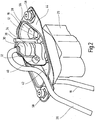
- the trough-like collecting part 16 is fixed by nuts 28, which are so far pressed into the chamber structure. Especially in the Fig.2 a pertinent nut 28 is shown, wherein at the diametrically opposite edge of the tub and not shown in more detail is a further fixed nut is.
- the collecting part 16 also has the task, inter alia as a function of the temperature conditions, of serving as heat shielding of the injection system.
- the collecting part 16 is preferably formed in the manner of a sheet metal forming part, for example in the manner of a deep-drawn part, and moreover can have a structure comparable to known heat shield structures in this area.
- a protective part 30 is arranged as a further collecting part, which preferably prevents the direct impinging path of the medium between an exit point 12 and the one collecting part 10 in the manner of a spray or splash guard.
- the structure of the pertinent protection part 30 is more detailed in FIG Figure 3 played. As shown by the Figure 3 is the protective part 30 of two flap parts 32,34 formed adjacent to each other along a common bending or folding line 36 to form a cylindrical receiving space 38 folded towards each other and via a conventional screw 40 (see. Fig.2 ) are connectable to each other.
- the protective part 30 extends substantially perpendicular to the tub bottom 42 of the trough-shaped collecting part 16, at the tub rim 44, the flanged or folded wall portions 46 of the upper part of the collecting part 10 sealingly by support connect (see also Figure 4 ).
- the receiving space 38 formed by the two superimposed flap parts 32,34 relative to the environment also sealed in the region of the fuel line 26 and each exiting from the exit point 12 medium would first impact on the inner wall 54 when the protective member 30 applied.
- a jet-like discharge of fluid could be effectively captured in such a way and if gaseous media components occurring, the protective part 30 in the direction of the Fig.1 should leave at the bottom, since at the lower exit point so far, the addressed seal 48,52 is interrupted, the upper part of the collecting part 10 would cause the formation of condensation together with the aforementioned collection function.
- further exit points for example, in the region of the transition from fuel line 26 to injector 22 or injection valve.
- protector 30 cooperate with collecting part 10 in the manner outlined.
- the addressed seals are arranged captive within the system parts of the security system.
- the collecting part 10 with its two trough-like upper and lower cover parts acts as a temperature shield of the injection system with respect to a possibly adjacent and guided there exhaust system, For example, used for a turbocharger of a diesel engine od.
- a turbocharger of a diesel engine od For example, used for a turbocharger of a diesel engine od.
- a conventional screw 58 For connecting upper cover of the collecting part 10 with lower cover in the form of the collecting container 16 is a conventional screw 58 (see. Figure 4 ).
Landscapes
- Engineering & Computer Science (AREA)
- Chemical & Material Sciences (AREA)
- Combustion & Propulsion (AREA)
- Mechanical Engineering (AREA)
- General Engineering & Computer Science (AREA)
- Exhaust Gas After Treatment (AREA)
Description
- Die Erfindung betrifft ein Sicherheitssystem zur Verhinderung des Austretens von schädigenden Medien aus einem Einspritzsystem eines Abgassystems eines Dieselmotors.
- Die Erfindung betrifft des weiteren ein Verfahren zum Betrieb eines dahingehenden Sicherheitssystems.
- Aus der
WO2006/059050 A1 ist ein Kapselsystem für eine Hochdruckkraftstoffleitung bekannt. Das Kapselsystem ist dazu vorgesehen, eine Schraubstelle zwischen einer Hochdruckpumpe und einer Kraftstoffleitung zu umkapseln. Die Umkapselung ist aus Kunststoff gebildet. - Beim Zusammenwirken von Baukomponenten, die insbesondere der Fluidführung dienen, kommt es immer wieder zu Undichtigkeitsstellen, die ungewollt mögliche Austrittsstellen für schädigende Medien darstellen, die häufig gasartig vernebelt als aggressive Mediendämpfe (Säuren, Laugen, Giftstoffe etc.) sowie in der Art explosiver Gasgemische und/oder leicht entzündbarer Stoffe aus dem Fluidführungssystem austreten und ein entsprechendes Sicherheitsrisiko für die Umgebung darstellen einschließlich der schädigenden Wirkung für die Umwelt. Dahingehende Problemfälle treten insbesondere in der chemischen Verfahrenstechnik, in der Raffination von Kraftstoff und dessen Abgabe über Zapfanlagen, bei Hydraulikanlagen und insbesondere beim Betrieb von Dieselmotoren und sonstigen Verbrennungskraftmaschinen auf.
- Ausgehend von der dahingehenden Problemstellung setzt nun das erfindungsgemäße Sicherheitssystem nach Anspruch 1 nebst Verfahren zu seinem Betrieb nach Anspruch 8 an und schlägt erfindungsgemäß vor, die gegebenenfalls ungewollt aus einer möglichen Austrittsstelle entweichenden, heißen, gasförmigen sowie schädigenden Medien an einem Auffangteil kondensieren zu lassen, um dann das Kondensat sicher und definiert aus dem Auffangteil abführen zu können, ohne dass das angesprochene entwichene Medium mit der Umgebung noch in Berührung kommen kann. Dergestalt lassen sich nicht nur aggressive Medien, wie gasförmige Säuren, Laugen oder Gifte, auffangen und beherrschen, sondern auch kraftstoffbehaftete Gase, wie heiße, treibstoffgesättigte Luft, ohne dass diese gegebenenfalls mit sonstigen heißen Bauteilen, wie Motoren- oder Abgaskomponenten (Turbolader) in Berührung kommen, was gegebenenfalls einen Brand oder gar eine Explosion an einem Fahrzeug, wie Kraftfahrzeugen, Lastkraftwagen, Omnibussen, aber auch Schiffen, auslösen könnte.
- Es ist für einen Durchschnittsfachmann auf dem Gebiet der dahingehenden Sicherheitstechnik überraschend, dass er durch Vorsehen eines Kondensat-Auffangteils in der Nähe des Gefahrenherdes schädliche Medien durch Auskondensieren abfangen und definiert abführen kann, ohne dass hierfür ein erheblicher apparatetechnischer Sicherheitsaufbau notwendig wäre. Die erfindungsgemäße Lösung ist kostengünstig realisierbar und erlaubt bei etwaigen Wartungs- und Überprüfungsarbeiten eine gute Zugänglichkeit zu der möglichen Undichtigkeits- oder Austrittsstelle, so dass auch insoweit Kosten reduzierbar sind.
- Bei einer besonders bevorzugten Ausführungsform des Sicherheitssystems ist vorgesehen, dass zwischen dem einen Auffangteil und der jeweiligen Austrittsstelle als weiteres Auffangteil ein Schutzteil vorhanden ist, das in der Art eines Sprüh- oder Spritzschutzes den direkten Auftreffweg des Mediums zwischen Austrittsstelle und dem einen Auffangteil unterbricht. Tritt das jeweilige Medium mit Schädigungspotential aus einer Undichtigkeits- oder Austrittsstelle aus, kann dies auch zunächst in Fluidform unter hohem Druck und hoher Temperatur erfolgen, so dass ein dahingehender Strahl auch in Form von Einzelspritzern oder Sprühanteilen durch das vorstehend beschriebene eine Auffangteil des Sicherheitssystems nur schwer beherrschbar wäre. Um auch dahingehenden Extremfällen gerecht zu werden, bildet das Schutzteil als weiteres Auffangteil, vorzugsweise ausgebildet in der Art einer temperaturbeständigen Schutzkappe, ein Hindernis für die Fluidanteile des Mediums, so dass diese insoweit zurückgehalten werden und nur die angesprochenen mediengesättigten Gasanteile und Gasgemische des Leckagestroms in Berührung mit dem einen Auffangteil unter Kondensatbildung kommen. Dergestalt ist in der Art eines Mehrschalensystems ein redundanter Sicherheitsaufbau erreicht.
- Das erfindungsgemäße Sicherheitssystem hat sich gemäß der Merkmalsausgestaltung des Patentanspruches 8 insbesondere für ein Betriebsverfahren geeignet erwiesen, bei dem in einem Abgassystem befindliche Verschmutzungen, wie bei der Dieselverbrennung entstehende Rußpartikel, mittels Kraftstoffeinspritzung nachverbrannt werden, wobei etwaig aus einer ungewollt vorhandenen Austrittsstelle des Abgassystems austretende heiße, treibstoffgesättigte Luft sich an dem Auffangteil des Sicherheitssystems niederschlägt und als Kondensat aus dem Auffangteil abgeführt wird. Mit der dahingehenden Verfahrenstechnik unter Einsatz des genannten Sicherheitssystems ist es also möglich, zur Erfüllung erhöhter Abgasnormen, in einem Abgassystem eines Fahrzeugs etwaig auftretende Rußanteile eines Dieselkraftstoffs od. dgl. nachzuverbrennen, wobei dann aufgrund etwaiger Leckagen ungewollt austretende heiße, treibstoffgesättigte Luft von dem Sicherheitssystem aufgefangen und dergestalt neutralisiert wird, dass die angesprochenen Gase oder Dämpfe nicht mit sonstigen heißen Motoren- und Abgaskomponenten unter Bildung von Brand- oder Explosionsherden in Verbindung kommen können.
- Weitere vorteilhafte Ausführungsformen sind Gegenstand der sonstigen Unteransprüche.
- Im folgenden wird das erfindungsgemäße Sicherheitssystem sowie das Verfahren zu seinem Betrieb anhand eines Ausführungsbeispiels für eine dahingehende Sicherheitseinrichtung nach der Zeichnung näher erläutert. Es zeigen dabei in prinzipieller und nicht maßstäblicher Darstellung die
- Fig.1
- teilweise in aufgeschnittener Darstellung die Frontansicht auf den grundlegenden Aufbau des Sicherheitssystems;
- Fig.2
- in perspektivischer Ansicht eine Draufsicht auf den unteren Teil des Sicherheitssystems;
- Fig.3
- in aufgeklappter, perspektivischer Ansicht einen Teil des Sicherheitssystems nach der
Fig.2 ; - Fig.4
- in perspektivischer Frontansicht das geschlossene Sicherheitssystem gemäß der Ausgestaltung nach der
Fig.1 . - Das in den Figuren dargestellte Sicherheitssystem dient zur Verhinderung des Austretens von schädigenden Medien, wie explosiven Gasgemischen und/oder entzündbaren Stoffen, beispielsweise in Form leicht entzündbarer Kraftstoffe od. dgl.. Das erfindungsgemäße Sicherheitssystem weist ein als Ganzes mit 10 bezeichnetes Auffangteil auf, das in abdichtender Weise eine mögliche Austrittsstelle 12 für das jeweilige Medium zumindest teilweise umfaßt. Tritt ein dahingehender Vorfall eines ungewollten Medienaustritts auf, besteht die Möglichkeit, dass das Medium sich an dem Auffangteil 10 niederschlägt, insbesondere dort auskondensiert, um im Auffangteil 10 gesammelt aus diesem abgeleitet zu werden. Dergestalt ist über das Auffangteil 10 sichergestellt, dass nicht ungewollt sicherheitstechnisch bedenkliche Medien weder in die Umgebung austreten können, noch dass sie die Umwelt schädigen und/oder an sonstigen heißen Komponenten eines nicht näher aufgezeigten fluidführenden Systems sich entzünden können, wie bei verfahrenstechnischen Anlagen, Hydraulikaggregaten oder Verbrennungsmotoren einschließlich Dieselmotoren etc..
- Das Auffangteil 10 umfaßt wannenartig die mögliche Austrittsstelle 12 für das jeweilige Medium derart mit einem vorgebbaren Abstand, dass das aufzufangende Medium sich zumindest teilweise, sofern in gesättigter Luft- oder Gasform vorliegend, kondensierend an einer Wand 14 des Auffangteils 10 niederschlägt, um als Kondensat in einem Sammelteil 16 des Auffangteils 10 aufgenommen aus diesem abgeleitet zu werden. Gemäß der Gesamtdarstellung nach der
Fig.1 ist das Auffangteil 10 mit Sammelteil 16 einstückig als Blechumformteil ausgebildet; es besteht aber auch vorzugsweise die Möglichkeit des mehrteiligen Aufbaues, wie in denFig.2 bis 4 dargestellt, die die bevorzugte Ausgestaltung des Sicherheitssystems wiedergeben. Das wannenartige Sammelteil 16 ist an seiner tiefsten Stelle mit einer Auslaß- oder Rückführleitung 18 versehen, die die Kondensatanteile einschließlich etwaiger Verschmutzungen sowie sonstigen Rückständen aus dem Sicherheitssystem für eine definierte Weiterverwendung, beispielsweise für eine Rückführung in einen Systemtank, eine Sammeleinrichtung od. dgl., aufnimmt (nicht dargestellt). - Gemäß der Darstellung nach der
Fig.1 ist die Verwendung des Sicherheitssystems für ein Abgassystem 20 eines Dieselmotors (nicht dargestellt) aufgezeigt. Der inFig.1 gezeigte Teil des Abgassystems 20 weist ein Einspritzventil oder eine Einspritzdüse 22 auf, die mit ihrem einen freien Ende in einen nicht näher dargestellten Brennraum mündet, der von einer Düsen- oder Brennkammer 24 umfaßt ist, die Bestandteil einer nicht näher dargestellten größeren Brenneranordnung sein kann. Die in derFig.1 gezeigte Einspritzdüse 22 ist an ihrem anderen freien Ende an eine Kraftstoffleitung 26 angeschlossen, die die Einspritzdüse 22 versorgt und sicherstellt, dass eingespritzter Kraftstoff in die Brennkammer mit ihrem Brennraum gelangen kann. - Die beschriebene Anordnung dient dazu, im Abgasstrom eines Dieselmotors verbleibende Ruß- oder sonstige Schmutzpartikelanteile nachzuverbrennen, und zwar mittels des über die Einspritzdüse 22 eingespritzten und gezündeten Kraftstoffes. Durch die beschriebene Nachverbrennung lassen sich die erhöhten sehr strengen Abgasnormen auch für die Zukunft einhalten, was mit dem bisher üblichen Katalysator-System dergestalt nicht möglich ist. Bei der beschriebenen Nachverbrennung kann aber nun nicht ausgeschlossen werden, dass über etwaige Undichtigkeitsstellen ungewollt mindestens eine Austrittsstelle 12 gebildet ist, beispielsweise zwischen der Einspritzdüse 22 und den in
Fig.1 aufgezeigten Wandteilen der Brennkammer 24, in die die Einspritzdüse 22 vorzugsweise eingeschraubt ist. So ist aufgrund von Motorvibrationen nicht auszuschließen, dass sich die Einspritzdüse 22 lockert oder bei Montagevorgängen verkantet eingesetzt die dann mögliche Austrittsstelle schafft. Im dahingehenden Fall würde dann die bei der Nachverbrennung entstehende heiße, treibstoffgesättigte Luft aus der Kraftstoffeinspritzung und mithin aus der Brennkammer 24 austreten und könnte sich dann beispielhaft an sonstigen heißen Motoren- oder Abgaskomponenten entzünden mit der Folge, dass neben etwaiger Brandherde auch das Entstehen von Explosionsherden möglich wäre. Dem wirkt das beschriebene wannenartige Auffangteil 10 entgegen, indem es der heißen, treibstoffgesättigten Luft eben ermöglicht, dort auszukondensieren und das Kondensat überwiegend in Form von Treibstofftröpfchen kann dann an der Innenwand 14 des Auffangteils 10 sich schwerkraftbedingt nach unten zum Sammelteil 16 als Sammelbehälter bewegen und, wie bereits beschrieben, das Auffangteil 10 verlassen. - Zur Montage des Auffangteils 10 an Teilen der Brennkammer 24 wird das wannenartige Sammelteil 16 über Muttern 28 festgelegt, die insoweit in die Kammerstruktur eingepreßt sind. Insbesondere in der
Fig.2 ist eine dahingehende Mutter 28 dargestellt, wobei am diametral gegenüberliegenden Wannenrand und nicht näher dargestellt sich eine weitere Festlegemutter befindet. Neben der Sammelfunktion kommt dem Sammelteil 16 unter anderem auch in Abhängigkeit der Temperaturverhältnisse die Aufgabe zu, als Hitzeabschirmung des Einspritzsystems zu dienen. Hierfür ist das Sammelteil 16 vorzugsweise in der Art eines Blechumformteils ausgebildet, beispielsweise in der Art eines Tiefziehteils, und kann darüber hinaus einen Aufbau vergleichbar zu bekannten Hitzeschildaufbauten in diesem Bereich aufweisen. - Zwischen dem Auffangteil 10 und der jeweiligen Austrittsstelle 12 ist als weiteres Auffangteil ein Schutzteil 30 angeordnet, das vorzugsweise in der Art eines Sprüh- oder Spritzschutzes den direkten Auftreffweg des Mediums zwischen einer Austrittsstelle 12 und dem einen Auffangteil 10 unterbindet. Der Aufbau des dahingehenden Schutzteils 30 ist detaillierter in
Fig.3 wiedergegeben. Gemäß der Darstellung nach derFig.3 ist das Schutzteil 30 aus zwei Klappenteilen 32,34 gebildet, die einander benachbart entlang einer gemeinsamen Biege- oder Falzlinie 36 unter Bildung eines zylindrischen Aufnahmeraumes 38 aufeinander zuklappbar und über eine übliche Schraubverbindung 40 (vgl.Fig.2 ) miteinander verbindbar sind. Wie des weiteren dieFig.2 darstellt, erstreckt sich das Schutzteil 30 im wesentlichen senkrecht zu dem Wannenboden 42 des wannenartig ausgebildeten Sammelteils 16, an dessen Wannenrand 44 sich die gleichfalls umgebördelten oder umgelegten Wandteile 46 des oberen Teils des Auffangteils 10 dichtend durch Auflage anschließen (vgl. hierzu auchFig.4 ). - Wie insbesondere die
Fig.3 zeigt, weist das eine Klappenteil 32 in einer eingeprägten Vertiefung eine bügel- oder klammerartige Dichtung 48 auf, wobei das andere zweite Klappenteil 34 im Durchgriffsbereich 50 für die Kraftstoffleitung 26 ein Stück einer ringsegmentartigen Dichtung 52 aufweist. Dergestalt ist der Aufnahmeraum 38 gebildet durch die beiden aufeinandergelegten Klappenteile 32,34 gegenüber der Umgebung auch im Bereich der Kraftstoffleitung 26 abgedichtet und jeweils aus der Austrittsstelle 12 austretendes Medium würde sich bei aufgebrachtem Schutzteil 30 zunächst an dessen Innenwand 54 niederschlagen. Insbesondere ein strahlartiger Austritt an Fluid (Dieselkraftstoff) ließe sich dergestalt wirksam einfangen und sofern auftretende gasförmige Medienanteile das Schutzteil 30 in Blickrichtung auf dieFig.1 gesehen nach unten hin verlassen sollten, da an der unteren Austrittsstelle insoweit auch die angesprochene Dichtung 48,52 unterbrochen ist, würde der obere Teil des Auffangteils 10 die Kondensatbildung nebst der angesprochenen Sammelfunktion veranlassen. Neben der bereits angesprochenen möglichen Austrittsstelle 12 besteht natürlich die Möglichkeit der Bildung weiterer Austrittsstellen, beispielsweise auch im Bereich des Übergangs von Kraftstoffleitung 26 zu Einspritzdüse 22 oder Einspritzventil. - In Abhängigkeit der Anwendungsaufgabe wirken vorzugsweise Schutzteil 30 mit Auffangteil 10 in der skizzierten Art und Weise zusammen. Es besteht aber grundsätzlich auch die Möglichkeit, das Schutzteil 30 wegzulassen und die maßgebende Schutzfunktion ausschließlich durch das Auffangteil 10 zu realisieren.
- Bei erhöhten Sicherheitsanforderungen, von denen aber grundsätzlich auszugehen ist, wird wohl das beschriebene Sicherheitssystem gemäß der Komplettdarstellung nach der
Fig. 4 zu betreiben sein. Um dahingehend eine wirksame Abdichtung zwischen Sammelteil 16 und oberem Kappenteil des Auffangteils 10 zu realisieren, weist das Sammelteil 16 umlaufend an der Übergangsstelle zwischen Wannenrand 44 und vertiefter Sammelstelle eine umlaufende Ringdichtung 56 auf, die wiederum in einer vertieften Ausprägung im Sammelteil 16 geführt ist. Um eine vollständige Abdichtung auch im Bereich der Auslaß- oder Rückführleitung 18 zu erreichen, weist wiederum vergleichbar der ringsegmentartigen Dichtung 52 bei der Ausnehmung des zweiten Klappenteils 34 auch der obere Wannenteil des Auffangteils 10 in einer entsprechenden kanalförmigen Bereichsausnehmung eine entsprechende segmentartige Dichtung (nicht dargestellt) auf. Vorzugsweise sind die angesprochenen Dichtungen unverlierbar innerhalb der Systemteile des Sicherheitssystems angeordnet. - Insgesamt fungiert das Auffangteil 10 mit seinen beiden wannenartigen Ober- und Unterdeckelteilen als Temperaturabschirmung des Einspritzsystems gegenüber einem etwaig benachbarten und dort geführten Abgassystems, beispielsweise eingesetzt für einen Turbolader eines Dieselmotors od. dgl.. Zum Verbinden von Oberdeckel des Auffangteils 10 mit Unterdeckel in Form des Sammelbehälters 16 dient eine übliche Schraubverbindung 58 (vgl.
Fig.4 ).
Claims (8)
- Sicherheitssystem zur Verhinderung des Austretens von schädigenden Medien aus einem Einspritzsystem eines Abgassystems (20) eines Dieselmotors mit mindestens einem Auffangteil (10), das in abdichtender Weise eine mögliche Austrittsstelle (12) zwischen einem Einspritzventil oder einer Einspritzdüse (22) und Wandteilen einer Brennkammer (24) für das jeweilige Medium zumindest teilweise umfasst, wobei sich das Medium an dem Auffangteil (10) niederschlägt und im Auffangteil (10) gesammelt aus diesem ableitbar ist, wobei das Auffangteil (10) ein wannenartiges Sammelteil (16) und eine Innenwand (14) besitzt und wobei
das Auffangteil (10) die mögliche Austrittsstelle (12) für das jeweilige Medium derart mit einem vorgebbaren Abstand umfaßt, dass das aufzufangende Medium sich zumindest teilweise an der Innenwand (14) des Auffangteils (10) kondensierend niederschlägt, um das im wannenartigen Sammelteil (16) des Auffangteils (10) aufgenommene Kondensat aus diesem abzuleiten, wobei das Kondensat überwiegend in Form von Treibstofftröpfchen an der Innenwand (14) schwerkraftbedingt nach unten zum Sammelteil (16) bewegbar ist, wobei das Sammelteil (16) an seiner tiefsten Stelle mit einer Auslaß- oder Rückführleitung (18) versehen ist und das Sammelteil (16) in der Art eines Blechumformteiles ausgebildet ist. - Sicherheitssystem nach Anspruch 1, dadurch gekennzeichnet, dass zwischen dem einen Auffangteil (10) und der jeweiligen Austrittsstelle (12) ein weiteres Auffangteil als Schutzteil (30) vorhanden ist, das in der Art eines Sprüh- oder Spritzschutzes den direkten Auftreffweg des Mediums zwischen Austrittsstelle (12) und dem einen Auffangteil (10) unterbricht.
- Sicherheitssystem nach Anspruch 2, dadurch gekennzeichnet, dass das Schutzteil (30) kappenartig und in abdichtender Weise zumindest teilweise Baukomponenten umfaßt, die in andere Baukomponenten mündend dergestalt eine mögliche Austrittsstelle (12) begrenzen.
- Sicherheitssystem nach Anspruch 3, dadurch gekennzeichnet, dass das Schutzteil (30) aus mindestens zwei Kappenteilen (32;34) gebildet ist, die einander benachbart entlang einer gemeinsamen Biege- oder Falzlinie (36) unter Bildung eines Aufnahmeraums (38) aufeinander zuklappbar und miteinander verbindbar sind.
- Sicherheitssystem nach einem der Ansprüche 2 bis 4, dadurch gekennzeichnet, dass das Schutzteil (30) sich im wesentlichen senkrecht zu dem Wannenboden (42) des wannenartig ausgebildeten Sammelteils (16) erstreckt, an dessen Wannenrand (44) sich die Wandteile (46) des einen Auffangteils (10) anschließen.
- Sicherheitssystem nach einem der Ansprüche 2 bis 5, dadurch gekennzeichnet, dass das Schutzteil (30) aus hitzebeständigen Materialien, wie einem Blechwerkstoff, besteht, aus dem vorzugsweise gleichfalls das eine Auffangteil (10) gebildet ist.
- Sicherheitssystem nach einem der Ansprüche 3 bis 6, dadurch gekennzeichnet, dass die Einspritzdüse oder das Einspritzventil (22) an eine Kraftstoffleitung (26) angeschlossen ist und in einen Brennraum mündet, der von der Brennkammer (24) umfaßt ist.
- Verfahren zum Betrieb eines Sicherheitssystems nach einem der Ansprüche 1 bis 7, dadurch gekennzeichnet, dass in einem Abgassystem (20) befindliche Verunreinigungen, wie Rußpartikel, mittels Kraftstoffeinspritzung nachverbrannt werden, und dass etwaig aus einer möglichen Austrittsstelle (12) des Abgassystems (20) austretende heiße, treibstoffgesättigte Luft sich an dem Auffangteil (10) des Sicherheitssystems niederschlägt und als Kondensat aus dem Auffangteil (10) abgeführt wird.
Priority Applications (1)
| Application Number | Priority Date | Filing Date | Title |
|---|---|---|---|
| EP06023980.3A EP1923563B1 (de) | 2006-11-18 | 2006-11-18 | Sicherheitssystem und Verfahren zu seinem Betrieb |
Applications Claiming Priority (1)
| Application Number | Priority Date | Filing Date | Title |
|---|---|---|---|
| EP06023980.3A EP1923563B1 (de) | 2006-11-18 | 2006-11-18 | Sicherheitssystem und Verfahren zu seinem Betrieb |
Publications (2)
| Publication Number | Publication Date |
|---|---|
| EP1923563A1 EP1923563A1 (de) | 2008-05-21 |
| EP1923563B1 true EP1923563B1 (de) | 2017-01-11 |
Family
ID=37944081
Family Applications (1)
| Application Number | Title | Priority Date | Filing Date |
|---|---|---|---|
| EP06023980.3A Active EP1923563B1 (de) | 2006-11-18 | 2006-11-18 | Sicherheitssystem und Verfahren zu seinem Betrieb |
Country Status (1)
| Country | Link |
|---|---|
| EP (1) | EP1923563B1 (de) |
Citations (1)
| Publication number | Priority date | Publication date | Assignee | Title |
|---|---|---|---|---|
| WO2006059050A1 (fr) * | 2004-12-03 | 2006-06-08 | Renault S.A.S | Dispositif de protection pour un tuyau d'alimentation en carburant |
Family Cites Families (6)
| Publication number | Priority date | Publication date | Assignee | Title |
|---|---|---|---|---|
| AT304181B (de) * | 1969-11-17 | 1972-12-27 | List Hans | Einspritz-Brennkraftmaschine |
| DE19541374C2 (de) * | 1995-11-07 | 1999-08-05 | Man Nutzfahrzeuge Ag | Entlüftungsventil für ein Kurbelgehäuse einer Brennkraftmaschine |
| DE10217383A1 (de) | 2002-04-18 | 2003-11-13 | Siemens Ag | Zylinderkopf-integriertes Dieseleinspritzsytem mit Ölsensor |
| FR2878577B1 (fr) | 2004-11-26 | 2009-04-24 | Renault Sas | Moteur de vehicule automobile a surface de recueil de gasoil continue |
| JP2006233821A (ja) * | 2005-02-23 | 2006-09-07 | Bosch Corp | 燃料噴射弁 |
| DE102005044934B4 (de) * | 2005-09-20 | 2022-06-02 | Elringklinger Ag | Sicherheitssystem und Verfahren zu seinem Betrieb |
-
2006
- 2006-11-18 EP EP06023980.3A patent/EP1923563B1/de active Active
Patent Citations (1)
| Publication number | Priority date | Publication date | Assignee | Title |
|---|---|---|---|---|
| WO2006059050A1 (fr) * | 2004-12-03 | 2006-06-08 | Renault S.A.S | Dispositif de protection pour un tuyau d'alimentation en carburant |
Also Published As
| Publication number | Publication date |
|---|---|
| EP1923563A1 (de) | 2008-05-21 |
Similar Documents
| Publication | Publication Date | Title |
|---|---|---|
| DE3111228C2 (de) | Verfahren und Vorrichtung zum Beseitigen von Ruß aus den Abgasen einer Brennkraftmaschine | |
| EP1939417B1 (de) | Abgasanlage für eine Brennkraftmaschine | |
| EP3620220B1 (de) | Filtervorrichtung | |
| DE102020126775B3 (de) | Haltevorrichtung für ein Einspritzventil eines Abgasbrenners und Abgasbrenner | |
| EP1369557B1 (de) | Kraftfahrzeug mit einem Diesel-Antriebsmotor mit mittels Kraftstoffdampfeindüsung diskontinuierlich regenerierbarem Abgasreinigungssystem | |
| EP3597898B1 (de) | Brennkraftmaschine mit einer in einem fluidführenden, fluidal mit einer tankentlüftungsleitung verbundenen bauteil vorgesehene venturidüse | |
| EP2405102A1 (de) | Gasturbine mit Balgdichtung | |
| EP2845636A1 (de) | Filterelement und Verfahren zur Herstellung eines Filterelements | |
| DD273008A1 (de) | Vorrichtung zum reinigen von abgasen aus niederdruckprozessen | |
| DE102017206251B3 (de) | Wassertankeinrichtung für eine Brennkraftmaschine mit Wassereinspritzung | |
| DE202017101404U1 (de) | Flammen-Überwachungsanordnung für ein mit Brennstoff arbeitendes Heizgerät | |
| DE19920520C2 (de) | Vorrichtung zur Rückführung des Abgases einer Brennkraftmaschine | |
| DE102005044934B4 (de) | Sicherheitssystem und Verfahren zu seinem Betrieb | |
| EP1923563A1 (de) | Sicherheitssystem und Verfahren zu seinem Betrieb | |
| EP0440674B1 (de) | Kraftstoff-einspritzdüse für brennkraftmaschinen | |
| DE102020201169A1 (de) | Tankvorrichtung für ein Brennstoffzellensystem | |
| DE10057427B4 (de) | Vorrichtung zur Tarnung von Schiffen | |
| DE2952900C2 (de) | ||
| EP3623613A1 (de) | Brennkraftmaschine mit einem ventil und einem fluidführenden bauteil und verfahren zur überwachung einer verbindung zwischen einem ventil in einer tankentlüftungsleitung und einem fluidführenden bauteil | |
| EP1900933B1 (de) | Kraftstoffeinspritzventil | |
| DE10355105A1 (de) | Reinigungsvorrichtung | |
| DE102009027687A1 (de) | Antriebsaggregat | |
| DE102017120020A1 (de) | System, verfahren und vorrichtung zum nachweisen der verunreinigung von dieselabgasfluid | |
| DE69202723T2 (de) | Schockdämpfer für ein Strahlantriebssystem. | |
| DE102021102413A1 (de) | Kraftfahrzeug |
Legal Events
| Date | Code | Title | Description |
|---|---|---|---|
| PUAI | Public reference made under article 153(3) epc to a published international application that has entered the european phase |
Free format text: ORIGINAL CODE: 0009012 |
|
| AK | Designated contracting states |
Kind code of ref document: A1 Designated state(s): AT BE BG CH CY CZ DE DK EE ES FI FR GB GR HU IE IS IT LI LT LU LV MC NL PL PT RO SE SI SK TR |
|
| AX | Request for extension of the european patent |
Extension state: AL BA HR MK RS |
|
| 17P | Request for examination filed |
Effective date: 20080605 |
|
| 17Q | First examination report despatched |
Effective date: 20080704 |
|
| AKX | Designation fees paid |
Designated state(s): AT BE BG CH CY CZ DE DK EE ES FI FR GB GR HU IE IS IT LI LT LU LV MC NL PL PT RO SE SI SK TR |
|
| GRAP | Despatch of communication of intention to grant a patent |
Free format text: ORIGINAL CODE: EPIDOSNIGR1 |
|
| RIC1 | Information provided on ipc code assigned before grant |
Ipc: F02M 33/02 20060101ALN20160726BHEP Ipc: F02M 55/00 20060101AFI20160726BHEP |
|
| INTG | Intention to grant announced |
Effective date: 20160823 |
|
| GRAS | Grant fee paid |
Free format text: ORIGINAL CODE: EPIDOSNIGR3 |
|
| GRAA | (expected) grant |
Free format text: ORIGINAL CODE: 0009210 |
|
| STAA | Information on the status of an ep patent application or granted ep patent |
Free format text: STATUS: THE PATENT HAS BEEN GRANTED |
|
| AK | Designated contracting states |
Kind code of ref document: B1 Designated state(s): AT BE BG CH CY CZ DE DK EE ES FI FR GB GR HU IE IS IT LI LT LU LV MC NL PL PT RO SE SI SK TR |
|
| REG | Reference to a national code |
Ref country code: GB Ref legal event code: FG4D Free format text: NOT ENGLISH |
|
| REG | Reference to a national code |
Ref country code: CH Ref legal event code: EP |
|
| REG | Reference to a national code |
Ref country code: AT Ref legal event code: REF Ref document number: 861533 Country of ref document: AT Kind code of ref document: T Effective date: 20170115 |
|
| REG | Reference to a national code |
Ref country code: IE Ref legal event code: FG4D Free format text: LANGUAGE OF EP DOCUMENT: GERMAN |
|
| REG | Reference to a national code |
Ref country code: DE Ref legal event code: R096 Ref document number: 502006015326 Country of ref document: DE |
|
| REG | Reference to a national code |
Ref country code: LT Ref legal event code: MG4D |
|
| REG | Reference to a national code |
Ref country code: NL Ref legal event code: MP Effective date: 20170111 |
|
| PG25 | Lapsed in a contracting state [announced via postgrant information from national office to epo] |
Ref country code: NL Free format text: LAPSE BECAUSE OF FAILURE TO SUBMIT A TRANSLATION OF THE DESCRIPTION OR TO PAY THE FEE WITHIN THE PRESCRIBED TIME-LIMIT Effective date: 20170111 |
|
| PG25 | Lapsed in a contracting state [announced via postgrant information from national office to epo] |
Ref country code: LT Free format text: LAPSE BECAUSE OF FAILURE TO SUBMIT A TRANSLATION OF THE DESCRIPTION OR TO PAY THE FEE WITHIN THE PRESCRIBED TIME-LIMIT Effective date: 20170111 Ref country code: IS Free format text: LAPSE BECAUSE OF FAILURE TO SUBMIT A TRANSLATION OF THE DESCRIPTION OR TO PAY THE FEE WITHIN THE PRESCRIBED TIME-LIMIT Effective date: 20170511 Ref country code: FI Free format text: LAPSE BECAUSE OF FAILURE TO SUBMIT A TRANSLATION OF THE DESCRIPTION OR TO PAY THE FEE WITHIN THE PRESCRIBED TIME-LIMIT Effective date: 20170111 Ref country code: GR Free format text: LAPSE BECAUSE OF FAILURE TO SUBMIT A TRANSLATION OF THE DESCRIPTION OR TO PAY THE FEE WITHIN THE PRESCRIBED TIME-LIMIT Effective date: 20170412 |
|
| PG25 | Lapsed in a contracting state [announced via postgrant information from national office to epo] |
Ref country code: ES Free format text: LAPSE BECAUSE OF FAILURE TO SUBMIT A TRANSLATION OF THE DESCRIPTION OR TO PAY THE FEE WITHIN THE PRESCRIBED TIME-LIMIT Effective date: 20170111 Ref country code: BG Free format text: LAPSE BECAUSE OF FAILURE TO SUBMIT A TRANSLATION OF THE DESCRIPTION OR TO PAY THE FEE WITHIN THE PRESCRIBED TIME-LIMIT Effective date: 20170411 Ref country code: SE Free format text: LAPSE BECAUSE OF FAILURE TO SUBMIT A TRANSLATION OF THE DESCRIPTION OR TO PAY THE FEE WITHIN THE PRESCRIBED TIME-LIMIT Effective date: 20170111 Ref country code: PT Free format text: LAPSE BECAUSE OF FAILURE TO SUBMIT A TRANSLATION OF THE DESCRIPTION OR TO PAY THE FEE WITHIN THE PRESCRIBED TIME-LIMIT Effective date: 20170511 Ref country code: LV Free format text: LAPSE BECAUSE OF FAILURE TO SUBMIT A TRANSLATION OF THE DESCRIPTION OR TO PAY THE FEE WITHIN THE PRESCRIBED TIME-LIMIT Effective date: 20170111 Ref country code: PL Free format text: LAPSE BECAUSE OF FAILURE TO SUBMIT A TRANSLATION OF THE DESCRIPTION OR TO PAY THE FEE WITHIN THE PRESCRIBED TIME-LIMIT Effective date: 20170111 |
|
| REG | Reference to a national code |
Ref country code: DE Ref legal event code: R097 Ref document number: 502006015326 Country of ref document: DE |
|
| PG25 | Lapsed in a contracting state [announced via postgrant information from national office to epo] |
Ref country code: CZ Free format text: LAPSE BECAUSE OF FAILURE TO SUBMIT A TRANSLATION OF THE DESCRIPTION OR TO PAY THE FEE WITHIN THE PRESCRIBED TIME-LIMIT Effective date: 20170111 Ref country code: SK Free format text: LAPSE BECAUSE OF FAILURE TO SUBMIT A TRANSLATION OF THE DESCRIPTION OR TO PAY THE FEE WITHIN THE PRESCRIBED TIME-LIMIT Effective date: 20170111 Ref country code: EE Free format text: LAPSE BECAUSE OF FAILURE TO SUBMIT A TRANSLATION OF THE DESCRIPTION OR TO PAY THE FEE WITHIN THE PRESCRIBED TIME-LIMIT Effective date: 20170111 Ref country code: IT Free format text: LAPSE BECAUSE OF FAILURE TO SUBMIT A TRANSLATION OF THE DESCRIPTION OR TO PAY THE FEE WITHIN THE PRESCRIBED TIME-LIMIT Effective date: 20170111 Ref country code: RO Free format text: LAPSE BECAUSE OF FAILURE TO SUBMIT A TRANSLATION OF THE DESCRIPTION OR TO PAY THE FEE WITHIN THE PRESCRIBED TIME-LIMIT Effective date: 20170111 |
|
| PLBE | No opposition filed within time limit |
Free format text: ORIGINAL CODE: 0009261 |
|
| STAA | Information on the status of an ep patent application or granted ep patent |
Free format text: STATUS: NO OPPOSITION FILED WITHIN TIME LIMIT |
|
| PG25 | Lapsed in a contracting state [announced via postgrant information from national office to epo] |
Ref country code: DK Free format text: LAPSE BECAUSE OF FAILURE TO SUBMIT A TRANSLATION OF THE DESCRIPTION OR TO PAY THE FEE WITHIN THE PRESCRIBED TIME-LIMIT Effective date: 20170111 |
|
| REG | Reference to a national code |
Ref country code: DE Ref legal event code: R082 Ref document number: 502006015326 Country of ref document: DE Representative=s name: OBERDORFER, JUERGEN, DIPL.-ING.UNIV., DE |
|
| REG | Reference to a national code |
Ref country code: FR Ref legal event code: PLFP Year of fee payment: 12 |
|
| 26N | No opposition filed |
Effective date: 20171012 |
|
| PG25 | Lapsed in a contracting state [announced via postgrant information from national office to epo] |
Ref country code: SI Free format text: LAPSE BECAUSE OF FAILURE TO SUBMIT A TRANSLATION OF THE DESCRIPTION OR TO PAY THE FEE WITHIN THE PRESCRIBED TIME-LIMIT Effective date: 20170111 |
|
| PG25 | Lapsed in a contracting state [announced via postgrant information from national office to epo] |
Ref country code: MC Free format text: LAPSE BECAUSE OF FAILURE TO SUBMIT A TRANSLATION OF THE DESCRIPTION OR TO PAY THE FEE WITHIN THE PRESCRIBED TIME-LIMIT Effective date: 20170111 |
|
| GBPC | Gb: european patent ceased through non-payment of renewal fee |
Effective date: 20171118 |
|
| PG25 | Lapsed in a contracting state [announced via postgrant information from national office to epo] |
Ref country code: CH Free format text: LAPSE BECAUSE OF NON-PAYMENT OF DUE FEES Effective date: 20171130 Ref country code: LI Free format text: LAPSE BECAUSE OF NON-PAYMENT OF DUE FEES Effective date: 20171130 |
|
| PG25 | Lapsed in a contracting state [announced via postgrant information from national office to epo] |
Ref country code: LU Free format text: LAPSE BECAUSE OF NON-PAYMENT OF DUE FEES Effective date: 20171118 |
|
| REG | Reference to a national code |
Ref country code: BE Ref legal event code: MM Effective date: 20171130 |
|
| REG | Reference to a national code |
Ref country code: IE Ref legal event code: MM4A |
|
| PG25 | Lapsed in a contracting state [announced via postgrant information from national office to epo] |
Ref country code: IE Free format text: LAPSE BECAUSE OF NON-PAYMENT OF DUE FEES Effective date: 20171118 |
|
| PG25 | Lapsed in a contracting state [announced via postgrant information from national office to epo] |
Ref country code: GB Free format text: LAPSE BECAUSE OF NON-PAYMENT OF DUE FEES Effective date: 20171118 Ref country code: BE Free format text: LAPSE BECAUSE OF NON-PAYMENT OF DUE FEES Effective date: 20171130 |
|
| REG | Reference to a national code |
Ref country code: AT Ref legal event code: MM01 Ref document number: 861533 Country of ref document: AT Kind code of ref document: T Effective date: 20171118 |
|
| PG25 | Lapsed in a contracting state [announced via postgrant information from national office to epo] |
Ref country code: AT Free format text: LAPSE BECAUSE OF NON-PAYMENT OF DUE FEES Effective date: 20171118 |
|
| PG25 | Lapsed in a contracting state [announced via postgrant information from national office to epo] |
Ref country code: HU Free format text: LAPSE BECAUSE OF FAILURE TO SUBMIT A TRANSLATION OF THE DESCRIPTION OR TO PAY THE FEE WITHIN THE PRESCRIBED TIME-LIMIT; INVALID AB INITIO Effective date: 20061118 |
|
| PG25 | Lapsed in a contracting state [announced via postgrant information from national office to epo] |
Ref country code: CY Free format text: LAPSE BECAUSE OF NON-PAYMENT OF DUE FEES Effective date: 20170111 |
|
| PG25 | Lapsed in a contracting state [announced via postgrant information from national office to epo] |
Ref country code: TR Free format text: LAPSE BECAUSE OF FAILURE TO SUBMIT A TRANSLATION OF THE DESCRIPTION OR TO PAY THE FEE WITHIN THE PRESCRIBED TIME-LIMIT Effective date: 20170111 |
|
| PGFP | Annual fee paid to national office [announced via postgrant information from national office to epo] |
Ref country code: FR Payment date: 20201119 Year of fee payment: 15 |
|
| PG25 | Lapsed in a contracting state [announced via postgrant information from national office to epo] |
Ref country code: FR Free format text: LAPSE BECAUSE OF NON-PAYMENT OF DUE FEES Effective date: 20211130 |
|
| PGFP | Annual fee paid to national office [announced via postgrant information from national office to epo] |
Ref country code: DE Payment date: 20241119 Year of fee payment: 19 |