EP1923552B1 - Unité de commande de la température - Google Patents
Unité de commande de la température Download PDFInfo
- Publication number
- EP1923552B1 EP1923552B1 EP07120668.4A EP07120668A EP1923552B1 EP 1923552 B1 EP1923552 B1 EP 1923552B1 EP 07120668 A EP07120668 A EP 07120668A EP 1923552 B1 EP1923552 B1 EP 1923552B1
- Authority
- EP
- European Patent Office
- Prior art keywords
- flap
- control unit
- temperature control
- actuator
- outlet
- Prior art date
- Legal status (The legal status is an assumption and is not a legal conclusion. Google has not performed a legal analysis and makes no representation as to the accuracy of the status listed.)
- Not-in-force
Links
Images


Classifications
-
- F—MECHANICAL ENGINEERING; LIGHTING; HEATING; WEAPONS; BLASTING
- F02—COMBUSTION ENGINES; HOT-GAS OR COMBUSTION-PRODUCT ENGINE PLANTS
- F02B—INTERNAL-COMBUSTION PISTON ENGINES; COMBUSTION ENGINES IN GENERAL
- F02B29/00—Engines characterised by provision for charging or scavenging not provided for in groups F02B25/00, F02B27/00 or F02B33/00 - F02B39/00; Details thereof
- F02B29/04—Cooling of air intake supply
- F02B29/0406—Layout of the intake air cooling or coolant circuit
- F02B29/0418—Layout of the intake air cooling or coolant circuit the intake air cooler having a bypass or multiple flow paths within the heat exchanger to vary the effective heat transfer surface
-
- Y—GENERAL TAGGING OF NEW TECHNOLOGICAL DEVELOPMENTS; GENERAL TAGGING OF CROSS-SECTIONAL TECHNOLOGIES SPANNING OVER SEVERAL SECTIONS OF THE IPC; TECHNICAL SUBJECTS COVERED BY FORMER USPC CROSS-REFERENCE ART COLLECTIONS [XRACs] AND DIGESTS
- Y02—TECHNOLOGIES OR APPLICATIONS FOR MITIGATION OR ADAPTATION AGAINST CLIMATE CHANGE
- Y02T—CLIMATE CHANGE MITIGATION TECHNOLOGIES RELATED TO TRANSPORTATION
- Y02T10/00—Road transport of goods or passengers
- Y02T10/10—Internal combustion engine [ICE] based vehicles
- Y02T10/12—Improving ICE efficiencies
Definitions
- the invention relates to a temperature control unit according to the preamble of claim 1.
- Devices are known with which the intake air temperature of internal combustion engines can be controlled. Such devices have an inlet and an outlet for the intake air. Through the inlet flows air, which z. B. from a turbocharger enters the device. If the air coming from the turbocharger is too hot, the intake air will be directed through a radiator before it can flow out through the outlet. For this purpose, corresponding radiator inlets and outlets are arranged on the device. This is how the abstract of the JP-A-61237998 an apparatus for switching a bypass port on a supercharger of a supercharged internal combustion engine, wherein a vacuum actuated flap switches a flow path through a charge air cooler.
- the object of the invention is to provide a temperature control unit with which the intake air temperature of an internal combustion engine is controllable.
- the temperature control unit should be simple and inexpensive to produce. This object is solved by the features of claim 1.
- the temperature control unit has a housing with an inlet and an outlet.
- a radiator outlet and a radiator inlet are provided, which are connectable to a radiator.
- the housing with the inlets and outlets is preferably made of plastic, in this case, plastics such.
- polyamide polyethylene, polypropylene or other thermoplastics filled or unfilled.
- fillers z.
- glass fibers graphite, talc or carbon fibers are used.
- a bypass window is provided which connects the inlet to the outlet with the radiator outlet closed.
- a flap is arranged in the housing, which is movable via an actuator.
- the actuator is z.
- the flap has an axis of rotation, which can be arranged both in an edge region and in a middle region. In an arrangement of the axis of rotation in the edge region, the flap pivots out of the flow cross section. In a centrally arranged axis of rotation, the flap remains in the open state in the flow cross-section and is flowed around by the intake air.
- the flap is connected via a connecting element with the actuator. The connecting element transmits the movement of the actuator to the flap.
- the actuator can perform rotational or translational movements.
- the flap is predominantly made of plastic, wherein a peripheral seal is arranged at the edges. Through the seal, the flap sealingly abuts the housing, thus preventing a portion of the intake air from flowing through the radiator.
- the seal can z. B. glued or welded on the flap.
- the seal is molded directly onto the flap.
- any elastomers can be used which have a suitable temperature resistance.
- the molded seal is made of a silicone, which is dimensionally stable even at higher temperatures.
- the seal may have any geometry, preferably slats are provided, which are easily deformable and can be easily put on bumps of the housing.
- the seal may be arranged on the outer circumference of the flap or on the front-side edge regions. Thus, an optimal investment of the seal is ensured on the housing wall.
- the connecting element extends through the bypass window with the radiator outlet closed and thus connects the flap to the actuator. With radiator outlet open closes the flap the bypass window, whereby the entire volume flow is passed through the radiator.
- the actuator is arranged with its center of rotation spaced from the pivot point of the flap.
- the actuator can be arranged at a location that offers itself for optimum space utilization.
- the actuator is rotatable by an angle ⁇ , wherein the rotation is transmitted through the connecting element to the flap.
- the flap performs a rotation by an angle ⁇ , which may be equal to or different from the angle ⁇ .
- the angle ⁇ of the actuator is greater than the angle ⁇ , which performs the flap.
- a temperature control unit 10 is shown in section.
- the temperature control unit 10 has an inlet 11 and an outlet 12.
- the inlets and outlets 11, 12 are integrated into a housing 13.
- This housing 13 has a radiator outlet 14 and a radiator inlet 15.
- the radiator outlet 14 is connected correspondingly to the inlet 11.
- the outlet 12 is connected corresponding to the radiator inlet 15.
- the flow path from the inlet 11 to the radiator outlet 14 can be closed by a flap 16.
- the flap 16 is connected to a connecting element 17 with an actuator 18.
- the connecting element 17 is arranged eccentrically on the actuator 18.
- the actuator can change its position.
- the flap 16 is moved by the connecting element 17 by the angle ⁇ in a closed or open position.
- the radiator outlet 14 is closed in such a way that the intake air is not can flow into a radiator K. This prevents further cooling of the intake air.
- the flap 16 closed the intake air flows through a bypass window 19, directly to the outlet 12.
- the bypass window 19 is closed by the flap 16'.
- the intake air flows through the radiator outlet 14 into the radiator K and is cooled there before it can flow back into the temperature control unit 10 through the radiator inlet 15. From the radiator inlet 15, the cooled intake air flows through a duct 20 to the outlet 12 (dashed arrow direction).
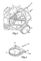
- FIG. 2 a temperature control unit 10 is shown in perspective view without a cover.
- the flap 16 is shown in the open state, so that the intake air can flow through the inlet 11 directly to the radiator outlet 14.
- the flap 16 forms part of the flow wall so that the intake air can be deflected by 90 °.
- the connecting element 17 is designed as a curved lever.
- the lever 17 is connected on the one hand with the flap 16 and on the other hand eccentrically with the actuator 18. At the connection points 23, the lever 17 relative movements to perform its mating partners 16 and 18.
- the lever 17 has bores on both sides in which pins are rotatably mounted.
- One pin is connected to the actuator and the other pin is connected to the flap.
- the flap 16 is mounted with its arranged in the edge region of rotation center d in plain bearings 24.
- FIG. 3 is a section of the temperature control unit 10 according to FIG. 2 shown.
- the flap 16 shown in the closed state, thus closing the radiator outlet 14. In this position, the flap 16, the bypass window 19 free, so that the intake air, which flows through the inlet 11 into the temperature control unit 10 is passed directly to the outlet 12 and can escape there from the temperature control unit.
- the flap 16 has an integrally formed bearing dome 25, on which the connecting element 17 is rotatably mounted.
- the bearing dome 25 is made of the same material as the flap 16.
- the flap 16 can be produced by injection molding, which eliminates further rework on the flap 16.
- FIG. 4 the flap 16 is shown in a perspective view.
- the flap 16 is designed as a pivoting flap which has a rotational axis d arranged in the edge region.
- bearing journals 26 are provided, which in the slide bearing 24 according to FIG. 2 and 3 intervention.
- the flap 16 is made of a thermoplastic, on which lip seals 21 are formed directly.
- the lip seal 21 surrounds a circular inner region 27 of the flap 16. In this case, the lip seal 21 projects beyond the material of the inner region 27, so that the lip seal 21 can rest directly against the walls 22 of the housing 13.
- the lip seal 21 z. B. be designed as a simple sealing bead or profile seal.
- the flap 16 with the molded seal 21 is simple and inexpensive to produce.
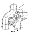
- FIG. 5 shows a temperature control unit 10. The same parts are provided here with the same reference numerals.
- the unit is flowed through from the radiator inlet 15 to the outlet 12 in accordance with the dotted line 33.
- a flap wall 30 closes this passage with respect to the inlet 11.
- the flap wall 30 is mounted on an axle (d) and connected to a transmission lever 28. This lever is coupled via a bearing pin 29 with a connecting element 17.
- the lever 17 is attached to an actuator 18.
- the actuator has a pivoting range of about 90 °.
- the housing 13 is preferably made of plastic and is manufactured by injection molding.
- the flap wall 30 is also made of plastic and can be made to improve the tightness in the 2K process, wherein the second component is a sealing component that provides the protrusions 32, 32a for the corresponding seal.
Landscapes
- Engineering & Computer Science (AREA)
- Physics & Mathematics (AREA)
- Thermal Sciences (AREA)
- Chemical & Material Sciences (AREA)
- Combustion & Propulsion (AREA)
- Mechanical Engineering (AREA)
- General Engineering & Computer Science (AREA)
- Supercharger (AREA)
- Control Of Throttle Valves Provided In The Intake System Or In The Exhaust System (AREA)
- Cooling, Air Intake And Gas Exhaust, And Fuel Tank Arrangements In Propulsion Units (AREA)
Claims (6)
- Unité de commande de température (10) pour l'air d'aspiration d'un moteur à combustion interne avec un turbocompresseur, présentant un boîtier (13) qui dispose d'une entrée (11), d'une sortie (12), d'une sortie de radiateur (14), d'une entrée de radiateur et d'une fenêtre de dérivation (19), un clapet (16) étant placé dans le boîtier (13) de manière à ce que la sortie de radiateur (14) puisse être ouverte et fermée au moyen du clapet, l'entrée (11) correspondant avec la sortie (12), lorsque la sortie de radiateur (14) est fermée, à travers la fenêtre de dérivation (19), un actionneur (18) relié au clapet (16) par un élément de jonction (17) étant prévu, caractérisée en ce que le clapet (16) est en majeure partie constitué de matière plastique et comporte un joint périphérique (21).
- Unité de commande de température selon la revendication 1, caractérisée en ce que le joint (21) est constitué d'un élastomère, le joint (21) étant injecté sur le clapet (16).
- Unité de commande de température selon l'une des revendications précédentes, caractérisée en ce que l'élément de jonction (17) traverse la fenêtre de dérivation (19) lorsque la sortie de radiateur (14) est fermée.
- Unité de commande de température selon l'une des revendications précédentes, caractérisée en ce que l'actionneur (18) dispose d'un centre de rotation D situé à une certaine distance d'un point de rotation du clapet (16).
- Unité de commande de température selon l'une des revendications précédentes, caractérisée en ce que l'actionneur (18) peut tourner d'un angle α et que la rotation peut être transférée au clapet (16) par l'élément de jonction (17) de sorte que le clapet (16) décrit une rotation d'un angle ß.
- Unité de commande de température selon la revendication 5, caractérisée en ce que l'angle α de l'actionneur (18) est plus grand que l'angle ß du clapet.
Applications Claiming Priority (1)
| Application Number | Priority Date | Filing Date | Title |
|---|---|---|---|
| DE102006054216 | 2006-11-15 |
Publications (3)
| Publication Number | Publication Date |
|---|---|
| EP1923552A2 EP1923552A2 (fr) | 2008-05-21 |
| EP1923552A3 EP1923552A3 (fr) | 2011-02-16 |
| EP1923552B1 true EP1923552B1 (fr) | 2013-07-24 |
Family
ID=38928462
Family Applications (1)
| Application Number | Title | Priority Date | Filing Date |
|---|---|---|---|
| EP07120668.4A Not-in-force EP1923552B1 (fr) | 2006-11-15 | 2007-11-14 | Unité de commande de la température |
Country Status (1)
| Country | Link |
|---|---|
| EP (1) | EP1923552B1 (fr) |
Families Citing this family (1)
| Publication number | Priority date | Publication date | Assignee | Title |
|---|---|---|---|---|
| FR2955620B1 (fr) * | 2010-01-26 | 2012-07-27 | Peugeot Citroen Automobiles Sa | Raccord, boitier de derivation pour ce raccord, systeme de refroidissement et vehicule equipe de ce raccord |
Family Cites Families (4)
| Publication number | Priority date | Publication date | Assignee | Title |
|---|---|---|---|---|
| SE460304B (sv) * | 1981-12-01 | 1989-09-25 | Volvo Ab | Anordning foer tillfoersel av foerbraenningsluft till cylindrarna i en foerbraenningsmotor |
| JPS61237998A (ja) * | 1985-04-15 | 1986-10-23 | Toyo Radiator Kk | 過給気バイパス装置を組込んだ過給器用放熱器 |
| DE4242010A1 (de) * | 1992-12-12 | 1994-06-16 | Man Nutzfahrzeuge Ag | Verfahren zur Regelung der Ladelufttemperatur, sowie Vorrichtung zu dessen Durchführung |
| DE10130065A1 (de) * | 2001-06-21 | 2003-01-02 | Deutz Ag | Aufgeladene Brennkraftmaschine |
-
2007
- 2007-11-14 EP EP07120668.4A patent/EP1923552B1/fr not_active Not-in-force
Also Published As
| Publication number | Publication date |
|---|---|
| EP1923552A2 (fr) | 2008-05-21 |
| EP1923552A3 (fr) | 2011-02-16 |
Similar Documents
| Publication | Publication Date | Title |
|---|---|---|
| DE69902129T2 (de) | Luftsteuervorrichtung für Klimaanlage | |
| EP1251255B1 (fr) | Dispositif d'admission | |
| DE112005003834B4 (de) | Verfahren und Vorrichtung zum Einstellen einer Öffneröffnung für einen Drosselkörper | |
| EP1200721B1 (fr) | Soupape | |
| DE102004056764B4 (de) | Drosselkörper und Verfahren zum Herstellen solcher Drosselkörper | |
| DE102009052372A1 (de) | Kühlergrillanordnung für einen Kraftwagen | |
| DE19854594A1 (de) | Drosselklappenstutzen | |
| DE102009017658A1 (de) | Ventileinheit, insbesondere zur Entlüftung eines Kurbelgehäuses einer Brennkraftmaschine und Kurbelgehäuseentlüftungssystem | |
| DE10105526A1 (de) | Vorrichtung zur Steuerung eines Gasstroms und Herstellverfahren derselben | |
| EP1923552B1 (fr) | Unité de commande de la température | |
| DE102009053830A1 (de) | Stellvorrichtung, Brennkraftmaschine und Verwendung | |
| DE19717347C1 (de) | Verfahren zum Herstellen einer Schaltklappe | |
| DE102010017636A1 (de) | Kühlluftführungssystem für ein Fahrzeug | |
| WO2012069516A1 (fr) | Système de ventilation pour véhicule | |
| EP1787049B1 (fr) | Soupape de piston rotatif et systeme de retour des gaz d'echappement comprenant une soupape de ce type | |
| DE102022114129B4 (de) | Dichtung und Ventilvorrichtung für einen Kühlmittelkreislauf eines Kraftfahrzeugs mit einer solchen Dichtung | |
| DE19819364B4 (de) | Drosselklappe | |
| DE202006011672U1 (de) | Zylinderkopfhaube | |
| DE102010060193B4 (de) | Schaltvorrichtung für eine Aufladeeinrichtung eines Verbrennungsmotors | |
| DE10101412A1 (de) | Abgasrückführeinrichtung für eine Brennkraftmaschine | |
| EP1824694B1 (fr) | Clapet pour un systeme d'aeration d'un vehicule | |
| DE10035607A1 (de) | Klappenventil mit dünnwandiger Rohrabdichtung | |
| DE102020109049B4 (de) | Steuerklappe | |
| DE202005006235U1 (de) | Ventileinheit | |
| DE102019103691A1 (de) | Abgas-Rückführ-Kühler für eine Brennkraftmaschine |
Legal Events
| Date | Code | Title | Description |
|---|---|---|---|
| PUAI | Public reference made under article 153(3) epc to a published international application that has entered the european phase |
Free format text: ORIGINAL CODE: 0009012 |
|
| 17P | Request for examination filed |
Effective date: 20080331 |
|
| AK | Designated contracting states |
Kind code of ref document: A2 Designated state(s): AT BE BG CH CY CZ DE DK EE ES FI FR GB GR HU IE IS IT LI LT LU LV MC MT NL PL PT RO SE SI SK TR |
|
| AX | Request for extension of the european patent |
Extension state: AL BA HR MK RS |
|
| PUAL | Search report despatched |
Free format text: ORIGINAL CODE: 0009013 |
|
| AK | Designated contracting states |
Kind code of ref document: A3 Designated state(s): AT BE BG CH CY CZ DE DK EE ES FI FR GB GR HU IE IS IT LI LT LU LV MC MT NL PL PT RO SE SI SK TR |
|
| AX | Request for extension of the european patent |
Extension state: AL BA HR MK RS |
|
| AKX | Designation fees paid |
Designated state(s): AT BE BG CH CY CZ DE DK EE ES FI FR GB GR HU IE IS IT LI LT LU LV MC MT NL PL PT RO SE SI SK TR |
|
| GRAP | Despatch of communication of intention to grant a patent |
Free format text: ORIGINAL CODE: EPIDOSNIGR1 |
|
| GRAS | Grant fee paid |
Free format text: ORIGINAL CODE: EPIDOSNIGR3 |
|
| GRAA | (expected) grant |
Free format text: ORIGINAL CODE: 0009210 |
|
| RIN1 | Information on inventor provided before grant (corrected) |
Inventor name: BEDOUET, CECILE Inventor name: MIGAUD, JEROME Inventor name: MARTEAU, CHRISTOPHE |
|
| AK | Designated contracting states |
Kind code of ref document: B1 Designated state(s): AT BE BG CH CY CZ DE DK EE ES FI FR GB GR HU IE IS IT LI LT LU LV MC MT NL PL PT RO SE SI SK TR |
|
| REG | Reference to a national code |
Ref country code: GB Ref legal event code: FG4D Free format text: NOT ENGLISH |
|
| REG | Reference to a national code |
Ref country code: CH Ref legal event code: EP |
|
| REG | Reference to a national code |
Ref country code: AT Ref legal event code: REF Ref document number: 623605 Country of ref document: AT Kind code of ref document: T Effective date: 20130815 |
|
| REG | Reference to a national code |
Ref country code: IE Ref legal event code: FG4D Free format text: LANGUAGE OF EP DOCUMENT: GERMAN |
|
| REG | Reference to a national code |
Ref country code: DE Ref legal event code: R096 Ref document number: 502007012071 Country of ref document: DE Effective date: 20130919 |
|
| REG | Reference to a national code |
Ref country code: NL Ref legal event code: VDEP Effective date: 20130724 |
|
| REG | Reference to a national code |
Ref country code: LT Ref legal event code: MG4D |
|
| PG25 | Lapsed in a contracting state [announced via postgrant information from national office to epo] |
Ref country code: IS Free format text: LAPSE BECAUSE OF FAILURE TO SUBMIT A TRANSLATION OF THE DESCRIPTION OR TO PAY THE FEE WITHIN THE PRESCRIBED TIME-LIMIT Effective date: 20131124 Ref country code: PT Free format text: LAPSE BECAUSE OF FAILURE TO SUBMIT A TRANSLATION OF THE DESCRIPTION OR TO PAY THE FEE WITHIN THE PRESCRIBED TIME-LIMIT Effective date: 20131125 Ref country code: LT Free format text: LAPSE BECAUSE OF FAILURE TO SUBMIT A TRANSLATION OF THE DESCRIPTION OR TO PAY THE FEE WITHIN THE PRESCRIBED TIME-LIMIT Effective date: 20130724 Ref country code: SE Free format text: LAPSE BECAUSE OF FAILURE TO SUBMIT A TRANSLATION OF THE DESCRIPTION OR TO PAY THE FEE WITHIN THE PRESCRIBED TIME-LIMIT Effective date: 20130724 Ref country code: CY Free format text: LAPSE BECAUSE OF FAILURE TO SUBMIT A TRANSLATION OF THE DESCRIPTION OR TO PAY THE FEE WITHIN THE PRESCRIBED TIME-LIMIT Effective date: 20130724 |
|
| PG25 | Lapsed in a contracting state [announced via postgrant information from national office to epo] |
Ref country code: GR Free format text: LAPSE BECAUSE OF FAILURE TO SUBMIT A TRANSLATION OF THE DESCRIPTION OR TO PAY THE FEE WITHIN THE PRESCRIBED TIME-LIMIT Effective date: 20131025 Ref country code: FI Free format text: LAPSE BECAUSE OF FAILURE TO SUBMIT A TRANSLATION OF THE DESCRIPTION OR TO PAY THE FEE WITHIN THE PRESCRIBED TIME-LIMIT Effective date: 20130724 Ref country code: LV Free format text: LAPSE BECAUSE OF FAILURE TO SUBMIT A TRANSLATION OF THE DESCRIPTION OR TO PAY THE FEE WITHIN THE PRESCRIBED TIME-LIMIT Effective date: 20130724 Ref country code: PL Free format text: LAPSE BECAUSE OF FAILURE TO SUBMIT A TRANSLATION OF THE DESCRIPTION OR TO PAY THE FEE WITHIN THE PRESCRIBED TIME-LIMIT Effective date: 20130724 Ref country code: SI Free format text: LAPSE BECAUSE OF FAILURE TO SUBMIT A TRANSLATION OF THE DESCRIPTION OR TO PAY THE FEE WITHIN THE PRESCRIBED TIME-LIMIT Effective date: 20130724 Ref country code: NL Free format text: LAPSE BECAUSE OF FAILURE TO SUBMIT A TRANSLATION OF THE DESCRIPTION OR TO PAY THE FEE WITHIN THE PRESCRIBED TIME-LIMIT Effective date: 20130724 |
|
| PG25 | Lapsed in a contracting state [announced via postgrant information from national office to epo] |
Ref country code: RO Free format text: LAPSE BECAUSE OF FAILURE TO SUBMIT A TRANSLATION OF THE DESCRIPTION OR TO PAY THE FEE WITHIN THE PRESCRIBED TIME-LIMIT Effective date: 20130724 Ref country code: CZ Free format text: LAPSE BECAUSE OF FAILURE TO SUBMIT A TRANSLATION OF THE DESCRIPTION OR TO PAY THE FEE WITHIN THE PRESCRIBED TIME-LIMIT Effective date: 20130724 Ref country code: EE Free format text: LAPSE BECAUSE OF FAILURE TO SUBMIT A TRANSLATION OF THE DESCRIPTION OR TO PAY THE FEE WITHIN THE PRESCRIBED TIME-LIMIT Effective date: 20130724 Ref country code: SK Free format text: LAPSE BECAUSE OF FAILURE TO SUBMIT A TRANSLATION OF THE DESCRIPTION OR TO PAY THE FEE WITHIN THE PRESCRIBED TIME-LIMIT Effective date: 20130724 Ref country code: DK Free format text: LAPSE BECAUSE OF FAILURE TO SUBMIT A TRANSLATION OF THE DESCRIPTION OR TO PAY THE FEE WITHIN THE PRESCRIBED TIME-LIMIT Effective date: 20130724 |
|
| PG25 | Lapsed in a contracting state [announced via postgrant information from national office to epo] |
Ref country code: IT Free format text: LAPSE BECAUSE OF FAILURE TO SUBMIT A TRANSLATION OF THE DESCRIPTION OR TO PAY THE FEE WITHIN THE PRESCRIBED TIME-LIMIT Effective date: 20130724 Ref country code: ES Free format text: LAPSE BECAUSE OF FAILURE TO SUBMIT A TRANSLATION OF THE DESCRIPTION OR TO PAY THE FEE WITHIN THE PRESCRIBED TIME-LIMIT Effective date: 20130724 |
|
| PLBE | No opposition filed within time limit |
Free format text: ORIGINAL CODE: 0009261 |
|
| STAA | Information on the status of an ep patent application or granted ep patent |
Free format text: STATUS: NO OPPOSITION FILED WITHIN TIME LIMIT |
|
| BERE | Be: lapsed |
Owner name: MANN+HUMMEL G.M.B.H. Effective date: 20131130 |
|
| REG | Reference to a national code |
Ref country code: CH Ref legal event code: PL |
|
| 26N | No opposition filed |
Effective date: 20140425 |
|
| GBPC | Gb: european patent ceased through non-payment of renewal fee |
Effective date: 20131114 |
|
| PG25 | Lapsed in a contracting state [announced via postgrant information from national office to epo] |
Ref country code: MC Free format text: LAPSE BECAUSE OF FAILURE TO SUBMIT A TRANSLATION OF THE DESCRIPTION OR TO PAY THE FEE WITHIN THE PRESCRIBED TIME-LIMIT Effective date: 20130724 Ref country code: LI Free format text: LAPSE BECAUSE OF NON-PAYMENT OF DUE FEES Effective date: 20131130 Ref country code: CH Free format text: LAPSE BECAUSE OF NON-PAYMENT OF DUE FEES Effective date: 20131130 |
|
| REG | Reference to a national code |
Ref country code: DE Ref legal event code: R097 Ref document number: 502007012071 Country of ref document: DE Effective date: 20140425 |
|
| REG | Reference to a national code |
Ref country code: DE Ref legal event code: R119 Ref document number: 502007012071 Country of ref document: DE Effective date: 20140603 |
|
| REG | Reference to a national code |
Ref country code: IE Ref legal event code: MM4A |
|
| PG25 | Lapsed in a contracting state [announced via postgrant information from national office to epo] |
Ref country code: DE Free format text: LAPSE BECAUSE OF NON-PAYMENT OF DUE FEES Effective date: 20140603 |
|
| PG25 | Lapsed in a contracting state [announced via postgrant information from national office to epo] |
Ref country code: BE Free format text: LAPSE BECAUSE OF NON-PAYMENT OF DUE FEES Effective date: 20131130 |
|
| PG25 | Lapsed in a contracting state [announced via postgrant information from national office to epo] |
Ref country code: IE Free format text: LAPSE BECAUSE OF NON-PAYMENT OF DUE FEES Effective date: 20131114 |
|
| PG25 | Lapsed in a contracting state [announced via postgrant information from national office to epo] |
Ref country code: GB Free format text: LAPSE BECAUSE OF NON-PAYMENT OF DUE FEES Effective date: 20131114 |
|
| REG | Reference to a national code |
Ref country code: AT Ref legal event code: MM01 Ref document number: 623605 Country of ref document: AT Kind code of ref document: T Effective date: 20131114 |
|
| PG25 | Lapsed in a contracting state [announced via postgrant information from national office to epo] |
Ref country code: AT Free format text: LAPSE BECAUSE OF NON-PAYMENT OF DUE FEES Effective date: 20131114 |
|
| PG25 | Lapsed in a contracting state [announced via postgrant information from national office to epo] |
Ref country code: TR Free format text: LAPSE BECAUSE OF FAILURE TO SUBMIT A TRANSLATION OF THE DESCRIPTION OR TO PAY THE FEE WITHIN THE PRESCRIBED TIME-LIMIT Effective date: 20130724 |
|
| PG25 | Lapsed in a contracting state [announced via postgrant information from national office to epo] |
Ref country code: BG Free format text: LAPSE BECAUSE OF FAILURE TO SUBMIT A TRANSLATION OF THE DESCRIPTION OR TO PAY THE FEE WITHIN THE PRESCRIBED TIME-LIMIT Effective date: 20130724 Ref country code: LU Free format text: LAPSE BECAUSE OF NON-PAYMENT OF DUE FEES Effective date: 20131114 Ref country code: HU Free format text: LAPSE BECAUSE OF FAILURE TO SUBMIT A TRANSLATION OF THE DESCRIPTION OR TO PAY THE FEE WITHIN THE PRESCRIBED TIME-LIMIT; INVALID AB INITIO Effective date: 20071114 |
|
| PG25 | Lapsed in a contracting state [announced via postgrant information from national office to epo] |
Ref country code: MT Free format text: LAPSE BECAUSE OF FAILURE TO SUBMIT A TRANSLATION OF THE DESCRIPTION OR TO PAY THE FEE WITHIN THE PRESCRIBED TIME-LIMIT Effective date: 20130724 |
|
| REG | Reference to a national code |
Ref country code: FR Ref legal event code: PLFP Year of fee payment: 9 |
|
| REG | Reference to a national code |
Ref country code: FR Ref legal event code: PLFP Year of fee payment: 10 |
|
| REG | Reference to a national code |
Ref country code: FR Ref legal event code: PLFP Year of fee payment: 11 |
|
| PGFP | Annual fee paid to national office [announced via postgrant information from national office to epo] |
Ref country code: FR Payment date: 20231120 Year of fee payment: 17 |
|
| P01 | Opt-out of the competence of the unified patent court (upc) registered |
Effective date: 20240220 |
|
| PG25 | Lapsed in a contracting state [announced via postgrant information from national office to epo] |
Ref country code: FR Free format text: LAPSE BECAUSE OF NON-PAYMENT OF DUE FEES Effective date: 20241130 |