EP1923545A2 - Heat recovery system - Google Patents
Heat recovery system Download PDFInfo
- Publication number
- EP1923545A2 EP1923545A2 EP07113857A EP07113857A EP1923545A2 EP 1923545 A2 EP1923545 A2 EP 1923545A2 EP 07113857 A EP07113857 A EP 07113857A EP 07113857 A EP07113857 A EP 07113857A EP 1923545 A2 EP1923545 A2 EP 1923545A2
- Authority
- EP
- European Patent Office
- Prior art keywords
- bypass
- opening
- heat recovery
- recovery system
- gas
- Prior art date
- Legal status (The legal status is an assumption and is not a legal conclusion. Google has not performed a legal analysis and makes no representation as to the accuracy of the status listed.)
- Granted
Links
Images


Classifications
-
- F—MECHANICAL ENGINEERING; LIGHTING; HEATING; WEAPONS; BLASTING
- F28—HEAT EXCHANGE IN GENERAL
- F28F—DETAILS OF HEAT-EXCHANGE AND HEAT-TRANSFER APPARATUS, OF GENERAL APPLICATION
- F28F27/00—Control arrangements or safety devices specially adapted for heat-exchange or heat-transfer apparatus
- F28F27/02—Control arrangements or safety devices specially adapted for heat-exchange or heat-transfer apparatus for controlling the distribution of heat-exchange media between different channels
-
- F—MECHANICAL ENGINEERING; LIGHTING; HEATING; WEAPONS; BLASTING
- F28—HEAT EXCHANGE IN GENERAL
- F28D—HEAT-EXCHANGE APPARATUS, NOT PROVIDED FOR IN ANOTHER SUBCLASS, IN WHICH THE HEAT-EXCHANGE MEDIA DO NOT COME INTO DIRECT CONTACT
- F28D21/00—Heat-exchange apparatus not covered by any of the groups F28D1/00 - F28D20/00
- F28D21/0001—Recuperative heat exchangers
- F28D21/0003—Recuperative heat exchangers the heat being recuperated from exhaust gases
-
- F—MECHANICAL ENGINEERING; LIGHTING; HEATING; WEAPONS; BLASTING
- F28—HEAT EXCHANGE IN GENERAL
- F28D—HEAT-EXCHANGE APPARATUS, NOT PROVIDED FOR IN ANOTHER SUBCLASS, IN WHICH THE HEAT-EXCHANGE MEDIA DO NOT COME INTO DIRECT CONTACT
- F28D7/00—Heat-exchange apparatus having stationary tubular conduit assemblies for both heat-exchange media, the media being in contact with different sides of a conduit wall
- F28D7/02—Heat-exchange apparatus having stationary tubular conduit assemblies for both heat-exchange media, the media being in contact with different sides of a conduit wall the conduits being helically coiled
- F28D7/024—Heat-exchange apparatus having stationary tubular conduit assemblies for both heat-exchange media, the media being in contact with different sides of a conduit wall the conduits being helically coiled the conduits of only one medium being helically coiled tubes, the coils having a cylindrical configuration
-
- F—MECHANICAL ENGINEERING; LIGHTING; HEATING; WEAPONS; BLASTING
- F28—HEAT EXCHANGE IN GENERAL
- F28F—DETAILS OF HEAT-EXCHANGE AND HEAT-TRANSFER APPARATUS, OF GENERAL APPLICATION
- F28F2250/00—Arrangements for modifying the flow of the heat exchange media, e.g. flow guiding means; Particular flow patterns
- F28F2250/06—Derivation channels, e.g. bypass
Definitions
- the invention relates to a heat recovery system with a boiler area and a bypass.
- the invention is therefore an object of the invention to provide a heat recovery system that is characterized by a structurally much simpler designed and cost gas well.
- the heat recovery system consists essentially of a boiler area, a bypass, at least one gas switch and an opening for supplying a gas and an opening for discharging the gas.
- the bypass and the boiler area are rotationally symmetrical and the boiler area is arranged concentrically around the bypass.
- the gas switch also has a stopper surfaces cooperating shut-off to supply the gas supplied wholly or partially to the boiler area or the bypass.
- the housing of the gas switch has a polygonal cross-section and the stop surfaces are straight.
- the proposed solution also requires no displacement body in the interior of the bypass, whereby an enormous space and material savings can be achieved.
- the at least one obturator is pivotable about a pivot axis.
- the gas switch has at least one, preferably a plurality of openings to the boiler area and at least one opening to the bypass and the obturator is provided on both sides with seals, the seals on one side with stop surfaces in the region leading to the boiler area opening and the seals on the other side cooperate with stop surfaces in the area of the opening leading to the bypass.
- shut-off valves are provided, the pivot axes of which are arranged on the sides of a quadrangle which forms the opening to the bypass.
- the gas switch can then be formed in particular cuboid, wherein the bypass leading to the opening in the upper side surface, the opening for supplying the gas in the lower side surface and four leading to the boiler area openings in the side surfaces of the parallelepiped gas switch are provided.
- the four shut-off devices can then be arranged with their pivot axes, in particular in the region of the four upper edges of the parallelepiped gas switch.
- shut-off valves are formed trapezoidal, each opening in the side surfaces is assigned a shut-off and all four shut-off valves are provided for closing the opening leading to the bypass, the shut-off thereby collapsible in the manner of a pyramid or a truncated pyramid are to close the opening leading to the bypass.
- shut-off devices are preferably arranged so that in the opened state of the bypass at least 70%, preferably at least 80%, in particular more than 90% of the cross section of the bypass are released. In the arrangement described above, it is also quite possible that 100% of the cross section is released.
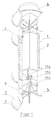
- the heat recovery system shown in Fig. 1 consists essentially of a boiler area 1, an internal bypass 2, a lower gas switch 3, an upper gas switch 4 and an opening 5 for supplying a gas and an opening 6 for discharging the gas. While the bypass 2 and the boiler area 1 are rotationally symmetrical and the boiler area is arranged concentrically around the bypass, the two gas switches 3, 4 have housing with an angular cross-section. Between the round opening 5 for feeding and the lower gas switch 3, therefore, a transition piece 7 is provided from a round to an angular cross-section. In a similar way between the lower gas switch 3 and the bypass 2, a transition piece 8 provided for the transition from square to round.
- the upper gas switch 4 is connected in the same way with transition pieces to the bypass 2 and to the opening 6.
- the upper gas switch 4 is formed in a corresponding manner and arranged only mirrored.
- the gas switch 3 has a housing 30 with a polygonal cross section.
- the housing 30 is formed in particular cuboid.
- an opening 31a leading to the bypass 2 is provided, while the gas is supplied through an opening 31b in the lower side surface.
- an opening 30c-30f leading to the boiler area is provided in each case.
- shut-off valves 32a-32d are provided, the pivot axes 33a-33b are arranged in the region of the four upper edges of the cuboid gas switch 3.
- the four shut-off elements 32a-32d are trapezoid-shaped, wherein each opening 31c-31f in the side faces of the housing 30 is assigned a shut-off element. Accordingly, these openings 31c-31f are also trapezoidal in shape.
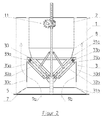
- All four shut-off valves 32a-32d are provided for closing the bypass-leading opening 31a, and the pyramid-type shut-off valves are collapsible to close the bypassing opening 31a (see FIGS. 2 and 3). In this position, the shut-off valves, the hot gases are directed according to the arrows 9a, 9b in the boiler area 1, wherein the pyramid-like shape favors the flow.
- the openings leading to the boiler area 32c-31f closed and the hot gases are passed through the bypass 2 according to the arrows 10a and 10b.
- the side walls of the housing 30 could be arranged inclined in the form of a truncated pyramid, whereby the inflow into the boiler area is favored.
- an adjusting mechanism is provided in the interior of the bypass 2, which adjusts at least one obturator, but preferably all the shut-off devices together.
- the adjustment mechanism is formed by a drivable gear 11a in conjunction with a first and a second drive block 11b, 11e, whereby the drive block 11b can be adjusted in the direction of the double arrow 11c in the longitudinal axis.
- the two sticks are thereby moved in opposite directions, so that one lantern moves up while the other lantern moves down and vice versa.
- the gear is driven by a motor located outside the bypass / boiler area.
- the shut-off devices 32a-32b are articulated via toggle 11d on the drive shaft 11b. In this way, a very simple and effective adjustment of the flaps between the two extreme positions.
- the trapezoidal shut-off devices in connection with the toggle lever drive enable a sensitive control behavior at the beginning of the opening process.
- shut-off elements of the lower and upper gas switches 3, 4 can be adjusted simultaneously in a particularly simple and reliable manner.
- This adjustment mechanism also offers the possibility to effect an independent and rapid closing of the openings leading to the boiler area in that the vertical linkage connected to the toggle levers with a Case weight is provided that can be released, for example, via an externally arranged electromagnetic clutch.
- shut-off devices 32a-32d can be formed flat.
- Each obturator is designed, for example, as a lattice structural wing with freely movable, gimbal-mounted wing plates, whereby a heat distortion can be avoided even at high and rapidly changing temperatures.
- the shut-off elements furthermore have seals 34a-34d, which cooperate with correspondingly straight or planar stop surfaces in the area of the openings 31c-31f leading to the boiler area or with corresponding stop surfaces in the area of the opening 31a leading to the bypass.
- the seals are formed for example by flexible stainless steel loops, which have a support member inside, in particular a V-shaped support member. Due to the straight or planar design of the shut-off devices, the corresponding stop surfaces are also straight or planar, so that a reliable seal can be ensured in a simple manner.
- the stop surfaces can be formed, for example, by corresponding struts 35a-35d, as can be seen in particular from FIGS. 2 and 5. It would also be conceivable that these struts are completely dispensed with and the shut-off elements come into contact with each other.
- the inventive solution of the gas switch is characterized by a very space and material-saving and cost-effective design.
Landscapes
- Engineering & Computer Science (AREA)
- Physics & Mathematics (AREA)
- Thermal Sciences (AREA)
- Mechanical Engineering (AREA)
- General Engineering & Computer Science (AREA)
- Control Of Steam Boilers And Waste-Gas Boilers (AREA)
- Temperature-Responsive Valves (AREA)
- Separation By Low-Temperature Treatments (AREA)
- Waste-Gas Treatment And Other Accessory Devices For Furnaces (AREA)
- Other Air-Conditioning Systems (AREA)
- Sliding Valves (AREA)
Abstract
Description
Die Erfindung betrifft ein Wärmerückgewinnungssystem mit einem Kesselbereich und einem Bypass.The invention relates to a heat recovery system with a boiler area and a bypass.
Bei derartigen Wärmerückgewinnungssystemen wurden vielfach der Kesselbereich und der Bypass in separaten Gehäusen untergebracht. Hierfür sind jedoch ein enormer Platzbedarf und aufwendige Stützgerüste erforderlich, was vor allem bei Off-Shore-Anlagen von großem Nachteil ist.In such heat recovery systems, the boiler area and the bypass were often housed in separate housings. For this purpose, however, an enormous space requirement and elaborate scaffolds are required, which is a major drawback, especially in off-shore systems.
Man hat daher ein Wärmerückgewinnungssystem mit einem Kessel und einem innenliegenden Bypass vorgeschlagen, wobei der Kessel konzentrisch um den Bypass angeordnet ist. Um den heißen Gasstrom wahlweise über den Kesselbereich oder den Bypass führen zu können, ist im unteren Bereich ein erster, axial verschiebbarer Ringschieber zum Absperren der zum Kesselbereich führenden Öffnung und im oberen Bereich ein zweiter, axial verschiebbarer Ringschieber zum Absperren des Bypasses vorgesehen. Die Verstellung der beiden Ringschieber erfolgt durch einen relativ aufwendigen, hydraulischen Antrieb.It has therefore proposed a heat recovery system with a boiler and an internal bypass, wherein the boiler is arranged concentrically around the bypass. In order to be able to conduct the hot gas flow either via the boiler area or the bypass, a first, axially displaceable annular slide for shutting off the opening leading to the boiler area and in the upper area a second, axially displaceable annular slide for shutting off the bypass is provided in the lower area. The adjustment of the two slide ring is done by a relatively expensive, hydraulic drive.
Die Besonderheit dieses bekannten Wärmerückgewinnungssystems besteht weiterhin darin, dass im Bypass ein rotationssymmetrischer Verdrängungskörper angeordnet ist, der sowohl unten als auch oben aus dem Bypass herausragt und Anschlagflächen für den zweiten Ringschieber bietet. Durch den zentralen Verdrängungskörper ist wiederum ein enormer Material und Platzbedarf erforderlich. Außerdem gestaltet sich die Abdichtung der Ringschieber als relativ aufwendig.The peculiarity of this known heat recovery system is further that in the bypass a rotationally symmetrical displacement body is arranged, which protrudes both below and above from the bypass and provides abutment surfaces for the second annular slide. By the central displacement body in turn an enormous amount of material and space is required. In addition, the sealing of the annular slide designed as relatively expensive.
Der Erfindung liegt daher die Aufgabe zugrunde, ein Wärmerückgewinnungssystem anzugeben, dass sich durch eine konstruktiv wesentlich einfacher ausgestaltete und kostengünstigere Gasweiche auszeichnet.The invention is therefore an object of the invention to provide a heat recovery system that is characterized by a structurally much simpler designed and cost gas well.
Erfindungsgemäß wird diese Lösung durch die Merkmale des Anspruches 1 gelöst.According to the invention, this solution is solved by the features of
Das erfindungsgemäße Wärmerückgewinnungssystem besteht im Wesentlichen aus einem Kesselbereich, einem Bypass, wenigstens einer Gasweiche sowie einer Öffnung zum Zuführen eines Gases und einer Öffnung zum Abführen des Gases. Der Bypass und der Kesselbereich sind dabei rotationssymmetrisch ausgebildet und der Kesselbereich ist konzentrisch um den Bypass angeordnet. Die Gasweiche weist ferner ein mit Anschlagflächen zusammenwirkendes Absperrorgan auf, um das zugeführte Gas ganz oder teilweise dem Kesselbereich oder dem Bypass zuzuführen. Das Gehäuse der Gasweiche weist einen eckigen Querschnitt auf und die Anschlagflächen sind gerade ausgebildet.The heat recovery system according to the invention consists essentially of a boiler area, a bypass, at least one gas switch and an opening for supplying a gas and an opening for discharging the gas. The bypass and the boiler area are rotationally symmetrical and the boiler area is arranged concentrically around the bypass. The gas switch also has a stopper surfaces cooperating shut-off to supply the gas supplied wholly or partially to the boiler area or the bypass. The housing of the gas switch has a polygonal cross-section and the stop surfaces are straight.
Die Besonderheit besteht darin, dass man die Gasweiche in einem eckigen Gehäuse unterbringt, obwohl der Kesselbereich, die Zuführleitungen und der Bypass durch rotationssymmetrische Teile gebildet werden. Auf diese Weise können plane Absperrorgane zum Einsatz kommen, die mit geraden/planen Anschlagflächen zusammenwirken. Dies stellt gegenüber gekrümmten Absperrorganen, die mit gekrümmten Anschlagflächen zusammenwirken, eine konstruktiv wesentlich einfachere Lösung dar. Um die Gasweiche einzubauen, sind lediglich zwei kurze Übergangsstücke für einen runden auf einen eckigen bzw. von einem eckigen auf einen runden Querschnitt erforderlich, die jedoch auf einfache Art und Weise kostengünstig realisiert werden können.The peculiarity is that it accommodates the gas gate in a square housing, although the boiler area, the supply lines and the bypass are formed by rotationally symmetrical parts. In this way, plane shut-off elements can be used, which interact with straight / flat stop surfaces. This is compared to curved shut-off devices, which interact with curved stop surfaces, a structurally much simpler solution. To install the gas switch, only two short transition pieces for a round to a square or a square to a round cross-section are required, however, to simple Way can be realized inexpensively.
Die vorgeschlagene Lösung benötigt auch keinen Verdrängungskörper im inneren des Bypasses, wodurch eine enorme Platz- und Materialeinsparung erreicht werden kann.The proposed solution also requires no displacement body in the interior of the bypass, whereby an enormous space and material savings can be achieved.
Weitere Ausgestaltung der Erfindung sind Gegenstand der Unteransprüche.Further embodiment of the invention are the subject of the dependent claims.
Gemäß einem bevorzugten Ausführungsbeispiel ist das wenigstens eine Absperrorgan um eine Schwenkachse schwenkbar.According to a preferred embodiment, the at least one obturator is pivotable about a pivot axis.
In einer weiteren Ausgestaltung weist die Gasweiche wenigstens eine, vorzugsweise mehrere Öffnungen zum Kesselbereich und wenigstens eine Öffnung zum Bypass auf und das Absperrorgan ist auf beiden Seiten mit Dichtungen versehen, wobei die Dichtungen auf der einen Seite mit Anschlagflächen im Bereich der zum Kesselbereich führenden Öffnung und die Dichtungen auf der anderen Seite mit Anschlagflächen im Bereich der zum Bypass führenden Öffnung zusammenwirken.In a further embodiment, the gas switch has at least one, preferably a plurality of openings to the boiler area and at least one opening to the bypass and the obturator is provided on both sides with seals, the seals on one side with stop surfaces in the region leading to the boiler area opening and the seals on the other side cooperate with stop surfaces in the area of the opening leading to the bypass.
Es wäre auch denkbar, lediglich eine Dichtung am Umfang der Absperrorgane anzubringen, welchen dann in beiden Endlagen in einen konischen Dichtsitz einfährt.It would also be conceivable to attach only a seal on the circumference of the shut-off, which then enters in both end positions in a conical sealing seat.
In einer bevorzugten Ausgestaltung der Erfindung sind vier Absperrorgane vorgesehen, deren Schwenkachsen an den Seiten eines Vierecks, welches die Öffnung zum Bypass bildet, angeordnet sind.In a preferred embodiment of the invention, four shut-off valves are provided, the pivot axes of which are arranged on the sides of a quadrangle which forms the opening to the bypass.
Die Gasweiche kann dann insbesondere quaderförmig ausgebildet sein, wobei die zum Bypass führende Öffnung in der oberen Seitenfläche, die Öffnung zur Zuführung des Gases in der unteren Seitenfläche und vier zum Kesselbereich führende Öffnungen in den Seitenflächen der quaderförmigen Gasweiche vorgesehen sind. Die vier Absperrorgane können dann mit ihren Schwenkachsen, insbesondere im Bereich der vier oberen Kanten der quaderförmigen Gasweiche angeordnet werden.The gas switch can then be formed in particular cuboid, wherein the bypass leading to the opening in the upper side surface, the opening for supplying the gas in the lower side surface and four leading to the boiler area openings in the side surfaces of the parallelepiped gas switch are provided. The four shut-off devices can then be arranged with their pivot axes, in particular in the region of the four upper edges of the parallelepiped gas switch.
Es ist weiterhin denkbar, dass die vier Absperrorgane trapezartig ausgebildet werden, wobei jeder Öffnung in den Seitenflächen ein Absperrorgan zugeordnet ist und alle vier Absperrorgane zum Verschließen der zum Bypass führende Öffnung vorgesehen sind, wobei die Absperrorgane dabei nach Art einer Pyramide bzw. eines Pyramidenstumpfs zusammenklappbar sind, um die zum Bypass führende Öffnung zu verschließen.It is also conceivable that the four shut-off valves are formed trapezoidal, each opening in the side surfaces is assigned a shut-off and all four shut-off valves are provided for closing the opening leading to the bypass, the shut-off thereby collapsible in the manner of a pyramid or a truncated pyramid are to close the opening leading to the bypass.
Die Absperrorgane werden vorzugsweise so angeordnet, dass im geöffneten Zustand des Bypasses wenigstens 70%, vorzugsweise wenigstens 80%, insbesondere mehr als 90% des Querschnitts des Bypasses freigegeben sind. Bei der obenbeschriebenen Anordnung ist es auch durchaus möglich, dass 100% des Querschnitts freigegeben wird.The shut-off devices are preferably arranged so that in the opened state of the bypass at least 70%, preferably at least 80%, in particular more than 90% of the cross section of the bypass are released. In the arrangement described above, it is also quite possible that 100% of the cross section is released.
Weitere Vorteile und Ausgestaltungen der Erfindung werden im Folgenden anhand der Beschreibung eines Ausführungsbeispieles und der Zeichnung näher erläutert.Further advantages and embodiments of the invention will be explained in more detail below with reference to the description of an embodiment and the drawing.
In der Zeichnung zeigen
- Fig. 1
- eine dreidimensionale Schnittdarstellung des Wärmerückgewinnungssystems,
- Fig. 2
- eine schematische Schnittdarstellung im Bereich der unteren Gasweiche bei geschlossenem Bypass,
- Fig. 3
- eine Ansicht der Gasweiche gemäß Fig. 2 von unten,
- Fig. 4
- eine schematische Schnittdarstellung im Bereich der unteren Gasweiche bei geöffnetem Bypass und
- Fig. 5
- eine Ansicht der Gasweiche gemäß Fig. 4 von unten.
- Fig. 1
- a three-dimensional sectional view of the heat recovery system,
- Fig. 2
- a schematic sectional view in the region of the lower gas gate with closed bypass,
- Fig. 3
- a view of the gas switch according to FIG. 2 from below,
- Fig. 4
- a schematic sectional view in the region of the lower gas gate with open bypass and
- Fig. 5
- a view of the gas switch according to FIG. 4 from below.
Das in Fig. 1 dargestellte Wärmerückgewinnungssystem besteht im Wesentlichen aus einem Kesselbereich 1, einem innenliegenden Bypass 2, einer unteren Gasweiche 3, einer oberen Gasweiche 4 sowie einer Öffnung 5 zum Zuführen eines Gases sowie einer Öffnung 6 zum Abführen des Gases. Während der Bypass 2 und der Kesselbereich 1 rotationssymmetrisch ausgebildet sind und der Kesselbereich konzentrisch um den Bypass angeordnet ist, weisen die beiden Gasweichen 3, 4 Gehäuse mit eckigem Querschnitt auf. Zwischen der runden Öffnung 5 zum Zuführen und der unteren Gasweiche 3 ist daher ein Übergangsstück 7 von einem runden auf einen eckigen Querschnitt vorgesehen. In entsprechender Weise ist zwischen der unteren Gasweiche 3 und dem Bypass 2 ein Übergangsstück 8 für den Übergang von eckig auf rund vorgesehen. Die obere Gasweiche 4 ist in gleicher Weise mit Übergangsstücken an den Bypass 2 bzw. an die Öffnung 6 angeschlossen.The heat recovery system shown in Fig. 1 consists essentially of a
Im Folgenden wird anhand der Fig. 2 bis 5 die untere Gasweiche 3 näher erläutert. Die obere Gasweiche 4 ist in entsprechender Weise ausgebildet und lediglich gespiegelt angeordnet.In the following, the
Die Gasweiche 3 weist ein Gehäuse 30 mit einem eckigen Querschnitt auf. Im dargestellten Ausführungsbeispiel ist das Gehäuse 30 insbesondere quaderförmig ausgebildet.The
In einer oberen Seitenfläche der Gasweiche ist eine zum Bypass 2 führende Öffnung 31a vorgesehen, während das Gas über eine Öffnung 31b in der unteren Seitenfläche zugeführt wird. In den vier Seitenflächen des quaderförmigen Gehäuses 30 ist jeweils eine zum Kesselbereich führende Öffnung 30c-30f vorgesehen. Weiterhin sind vier Absperrorgane 32a-32d vorgesehen, deren Schwenkachsen 33a-33b im Bereich der vier oberen Kanten der quaderförmigen Gasweiche 3 angeordnet sind.In an upper side surface of the gas switch, an opening 31a leading to the
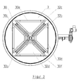
Wie insbesondere aus den Fig. 3 und Fig. 5 hervorgeht, sind die vier Absperrorgane 32a-32d trapezförmig ausgebildet, wobei jeder Öffnung 31c-31f in den Seitenflächen des Gehäuses 30 ein Absperrorgan zugeordnet ist. Diese Öffnungen 31c-31f sind dementsprechend auch trapezartig ausgebildet. Alle vier Absperrorgane 32a-32d sind zum Verschließen der zum Bypass führenden Öffnung 31a vorgesehen, wobei die Absperrorgane nach Art einer Pyramide bzw. eines Pyramidenstumpfs zusammenklappbar sind, um die zum Bypass führende Öffnung 31a zu verschließen (siehe Fig. 2 und 3). In dieser Stellung der Absperrorgane werden die heißen Gase entsprechend den Pfeilen 9a, 9b in den Kesselbereich 1 geleitet, wobei die pyramidenartige Form die Strömung begünstigt. In der in den Fig. 4 und 5 gezeigten Stellung der Absperrorgane werden die zum Kesselbereich führenden Öffnungen 32c-31f verschlossen und die heißen Gase werden gemäß den Pfeilen 10a und 10b durch den Bypass 2 geführt.As can be seen in particular from FIGS. 3 and 5, the four shut-off
Im Rahmen der Erfindung könnten die Seitenwände des Gehäuse 30 auch in Form eines Pyramidenstumpfs geneigt angeordnet werden, wodurch das Einströmen in den Kesselbereich begünstig wird.In the context of the invention, the side walls of the
Zur Verstellung der Absperrorgane 32a-32d ist im Inneren des Bypasses 2 ein Verstellmechanismus vorgesehen, der wenigstens ein Absperrorgan, vorzugsweise aber alle Absperrorgane gemeinsam verstellt. Im dargestellten Ausführungsbeispiel wird der Verstellmechanismus durch ein antreibbares Zahnrad 11a in Verbindung mit einem ersten und einem zweiten Triebstock 11b, 11e gebildet, wodurch der Triebstock 11b in Richtung des Doppelpfeils 11c in der Längsachse verstellt werden kann. Die beiden Triebstöcke werden dabei gegenläufig bewegt, so dass sich der eine Triebstock nach oben bewegt, während sich der andere Triebstock nach unten bewegt und umgekehrt. Das Zahnrad wird über einen außerhalb des Bypasses/Kesselbereichs angeordneten Motor angetrieben. Die Absperrorgane 32a-32b sind über Kniehebel 11d am Triebstock 11b angelenkt. Auf diese Weise erfolgt eine sehr einfache und wirkungsvolle Verstellung der Klappen zwischen den beiden Extremstellungen.To adjust the shut-off
Die trapezförmigen Absperrorgane in Zusammenhang mit dem Kniehebelantrieb ermöglichen ein feinfühliges Regelverhalten zu Beginn des Öffnungsvorgangs.The trapezoidal shut-off devices in connection with the toggle lever drive enable a sensitive control behavior at the beginning of the opening process.
Durch den gemeinsamen Verstellmechanismus können die Absperrorgane der unteren und der oberen Gasweiche 3, 4 gleichzeitig auf besonderes einfache und zuverlässige Weise verstellt werden.Due to the common adjustment mechanism, the shut-off elements of the lower and
Dieser Verstellmechanismus bietet darüber hinaus die Möglichkeit, ein unabhängiges und schnelles Verschließen der zum Kesselbereich führenden Öffnungen dadurch zu bewirken, dass das mit den Kniehebeln verbundene vertikale Gestänge mit einem Fallgewicht versehen wird, dass beispielsweise über eine außerhalb angeordnete Elektromagnetkupplung freigegeben werden kann.This adjustment mechanism also offers the possibility to effect an independent and rapid closing of the openings leading to the boiler area in that the vertical linkage connected to the toggle levers with a Case weight is provided that can be released, for example, via an externally arranged electromagnetic clutch.
Durch die eckige Konstruktion des Gehäuses 30 können die Absperrorgane 32a-32d plan ausgebildet werden. Jedes Absperrorgan wird beispielsweise als Gitter-Tragwerk-Flügel mit freibeweglichen, kardanisch befestigten Flügelblechen ausgebildet, wodurch auch bei hohen und rasch wechselnden Temperaturen ein Wärmeverzug vermieden werden kann.Due to the angular construction of the
Die Absperrorgane weisen ferner Dichtungen 34a-34d auf, die mit entsprechend gerade bzw. plan ausgebildeten Anschlagflächen im Bereich der zum Kesselbereich führenden Öffnungen 31c-31f bzw. mit entsprechenden Anschlagflächen im Bereich der zum Bypass führenden Öffnung 31a zusammenwirken.The shut-off elements furthermore have seals 34a-34d, which cooperate with correspondingly straight or planar stop surfaces in the area of the openings 31c-31f leading to the boiler area or with corresponding stop surfaces in the area of the opening 31a leading to the bypass.
Die Dichtungen werden beispielsweise durch flexible Edelstahlschlaufen gebildet, die im Inneren ein Stützorgan, insbesondere ein V-förmiges Stützorgan, aufweisen. Durch die gerade bzw. plane Ausbildung der Absperrorgane sind auch die entsprechenden Anschlagflächen gerade bzw. plan ausgebildet, so dass auf einfache Art und Weise eine zuverlässige Abdichtung gewährleistet werden kann.The seals are formed for example by flexible stainless steel loops, which have a support member inside, in particular a V-shaped support member. Due to the straight or planar design of the shut-off devices, the corresponding stop surfaces are also straight or planar, so that a reliable seal can be ensured in a simple manner.
Wenn die Absperrorgane zum Verschließen der zum Bypass führende Öffnung 31a pyramidenartig zusammengeführt werden, können die Anschlagflächen beispielsweise durch entsprechenden Streben 35a-35d gebildet werden, wie sie insbesondere aus den Fig. 2 und Fig. 5 zu erkennen sind. Es wäre aber auch denkbar, dass auf diese Streben völlig verzichtet wird und die Absperrorgane miteinander in Berührung kommen.When the shut-off devices for closing the bypass-leading opening 31a are brought together in a pyramid-like manner, the stop surfaces can be formed, for example, by corresponding
Durch die in den Fig. 2 und Fig. 4 gezeigte Anordnung der Schwenkachsen 33a-33d der Absperrorgane ist es möglich, im geöffneten Zustand des Bypasses 100% des Querschnitts des Bypasses freizugeben.By the arrangement of the pivot axes 33a-33d of the shut-off devices shown in FIGS. 2 and 4, it is possible to release 100% of the cross section of the bypass in the opened state of the bypass.
Die erfindungsgemäße Lösung der Gasweiche zeichnet sich durch eine sehr Platz und Material sparende und kostengünstige Konstruktion aus.The inventive solution of the gas switch is characterized by a very space and material-saving and cost-effective design.
Claims (11)
dadurch gekennzeichnet, dass die Gasweiche (3, 4) ein Gehäuse (30) mit einem eckigen Querschnitt aufweist und die Anschlagflächen gerade ausgebildet sind.Heat recovery system comprising a boiler area (1), a bypass (2), at least one gas switch (3, 4) and an opening (5) for supplying a gas and an opening (6) for discharging the gas, the bypass (2) and the boiler area is rotationally symmetrical and the boiler area is arranged concentrically around the bypass and the gas switch (3, 4) has at least one shut-off element (32a-33d) cooperating with stop surfaces in order to feed the supplied gas in whole or in part to the boiler area or the bypass,
characterized in that the gas switch (3, 4) has a housing (30) with a polygonal cross-section and the stop surfaces are straight.
Applications Claiming Priority (1)
| Application Number | Priority Date | Filing Date | Title |
|---|---|---|---|
| DE102006037773A DE102006037773A1 (en) | 2006-08-11 | 2006-08-11 | Heat recovery system e.g. for boiler system, has array, bypass and gas deflector with opening provided to feed gas and opening provided for removal of gas |
Publications (3)
| Publication Number | Publication Date |
|---|---|
| EP1923545A2 true EP1923545A2 (en) | 2008-05-21 |
| EP1923545A3 EP1923545A3 (en) | 2011-01-05 |
| EP1923545B1 EP1923545B1 (en) | 2011-07-13 |
Family
ID=38922118
Family Applications (1)
| Application Number | Title | Priority Date | Filing Date |
|---|---|---|---|
| EP07113857A Not-in-force EP1923545B1 (en) | 2006-08-11 | 2007-08-06 | Heat recovery system |
Country Status (4)
| Country | Link |
|---|---|
| EP (1) | EP1923545B1 (en) |
| AT (1) | ATE516423T1 (en) |
| DE (1) | DE102006037773A1 (en) |
| DK (1) | DK1923545T3 (en) |
Cited By (2)
| Publication number | Priority date | Publication date | Assignee | Title |
|---|---|---|---|---|
| WO2010013053A2 (en) | 2008-07-30 | 2010-02-04 | Heat Recovery Solutions Limited | Heat exchanger |
| WO2014098714A1 (en) * | 2012-12-20 | 2014-06-26 | Scania Cv Ab | Heat exchanger comprising bypass channels |
Families Citing this family (4)
| Publication number | Priority date | Publication date | Assignee | Title |
|---|---|---|---|---|
| IT1393595B1 (en) * | 2009-03-31 | 2012-04-27 | Materia S R L | FUME HEAT EXCHANGER |
| GB2515330B (en) | 2013-06-20 | 2015-11-04 | Boustead Internat Heaters Ltd | Improvements in waste heat recovery units |
| GB2561855A (en) * | 2017-04-25 | 2018-10-31 | Linde Aktiengesellshcaft | Heat exchanger and method for operating a heat exchanger |
| GB2601773B (en) * | 2020-12-09 | 2023-03-29 | Helical Energy Ltd | A heat exchange unit |
Citations (4)
| Publication number | Priority date | Publication date | Assignee | Title |
|---|---|---|---|---|
| GB1173717A (en) * | 1968-04-11 | 1969-12-10 | Vapor Corp | Heat Exchange Apparatus. |
| US4498524A (en) * | 1977-08-08 | 1985-02-12 | Jacobsen Orval E | Heat exchanger with by-pass |
| WO1999064806A1 (en) * | 1998-06-08 | 1999-12-16 | Alstom Uk Ltd. | Heat exchanger |
| US20050133202A1 (en) * | 2001-11-09 | 2005-06-23 | Aalborg Industries A/S | Heat exchanger, combination with heat exchanger and method of manufacturing the heat exchanger |
Family Cites Families (2)
| Publication number | Priority date | Publication date | Assignee | Title |
|---|---|---|---|---|
| DE2927161C2 (en) * | 1979-07-05 | 1985-10-03 | Pohl, Joachim, 5000 Köln | Method and device for heating water by recovering heat from the exhaust gases of a heating boiler |
| DE10047463A1 (en) * | 2000-09-21 | 2001-07-05 | J H K Anlagenbau Und Service G | Method for generating steam from ship's engine exhaust gases comprises feeding part of gases through bundle of tubes and remainder through central by-pass whose cross-section of flow can be varied by control valve |
-
2006
- 2006-08-11 DE DE102006037773A patent/DE102006037773A1/en not_active Withdrawn
-
2007
- 2007-08-06 AT AT07113857T patent/ATE516423T1/en active
- 2007-08-06 EP EP07113857A patent/EP1923545B1/en not_active Not-in-force
- 2007-08-06 DK DK07113857.2T patent/DK1923545T3/en active
Patent Citations (4)
| Publication number | Priority date | Publication date | Assignee | Title |
|---|---|---|---|---|
| GB1173717A (en) * | 1968-04-11 | 1969-12-10 | Vapor Corp | Heat Exchange Apparatus. |
| US4498524A (en) * | 1977-08-08 | 1985-02-12 | Jacobsen Orval E | Heat exchanger with by-pass |
| WO1999064806A1 (en) * | 1998-06-08 | 1999-12-16 | Alstom Uk Ltd. | Heat exchanger |
| US20050133202A1 (en) * | 2001-11-09 | 2005-06-23 | Aalborg Industries A/S | Heat exchanger, combination with heat exchanger and method of manufacturing the heat exchanger |
Cited By (6)
| Publication number | Priority date | Publication date | Assignee | Title |
|---|---|---|---|---|
| US20110180234A1 (en) * | 2008-07-29 | 2011-07-28 | Heat Recovery Solutions Limited | Heat exchanger |
| WO2010013053A2 (en) | 2008-07-30 | 2010-02-04 | Heat Recovery Solutions Limited | Heat exchanger |
| EP2713136A1 (en) | 2008-07-30 | 2014-04-02 | Heat Recovery Solutions Limited | Heat exchanger |
| US9080816B2 (en) * | 2008-07-30 | 2015-07-14 | Heat Recovery Solutions Limited | Exhaust recovery heat exchanger with inlet damper |
| US10526967B2 (en) | 2008-07-30 | 2020-01-07 | Heat Recovery Solutions Limited | Exhaust recovery heat exchanger with inlet damper |
| WO2014098714A1 (en) * | 2012-12-20 | 2014-06-26 | Scania Cv Ab | Heat exchanger comprising bypass channels |
Also Published As
| Publication number | Publication date |
|---|---|
| EP1923545B1 (en) | 2011-07-13 |
| ATE516423T1 (en) | 2011-07-15 |
| EP1923545A3 (en) | 2011-01-05 |
| DE102006037773A1 (en) | 2008-02-14 |
| DK1923545T3 (en) | 2011-10-24 |
Similar Documents
| Publication | Publication Date | Title |
|---|---|---|
| EP1923545B1 (en) | Heat recovery system | |
| DE2604152A1 (en) | SHUT-OFF VALVE | |
| DE2631764A1 (en) | SIX-WAY SWITCHING VALVE FOR LIQUID THROUGH PIPES | |
| DE202016106129U1 (en) | Multi-way ball valve | |
| EP1363012B1 (en) | Exhaust gas heat exchanger with valve | |
| EP0970330B1 (en) | Differential valve, specially a cabin air discharge valve in an aircraft, and method for regulating cabin pressure | |
| DE2349772C2 (en) | Shut-off device | |
| EP3447346A1 (en) | Valve, in particular servo valve | |
| DE3421653A1 (en) | Valve | |
| EP3236121B1 (en) | Shuttle valve for a safety valve apparatus and safety valve apparatus | |
| EP1637783B1 (en) | Valve combination for a steam turbine with a fast closing valve and a regulating valve | |
| EP3369972A1 (en) | Disc valve | |
| CH622326A5 (en) | ||
| EP1527295B1 (en) | Three-way ball valve | |
| EP1606540B1 (en) | Control valve with a short switching time | |
| EP2251603B1 (en) | Blocking system for large sections of piping with a swinging flap | |
| DE3525141A1 (en) | Steam conversion valve | |
| DE10163785A1 (en) | Device for interconnecting several hydraulic or pneumatic components, in particular several solenoid valves | |
| DE2035569B2 (en) | LOCKING VALVE WITH SMOOTH HOUSING PUSH AND MOVABLE, PRESSABLE SHUT-OFF PLATES | |
| DE4106630C2 (en) | ||
| WO2019007796A1 (en) | Valve | |
| WO2017076857A1 (en) | Fitting with maintenance opening | |
| DE508413C (en) | Gas and water valve for water heater | |
| DE1775464B1 (en) | Ring-shaped arrangement of flaps actuated by pressure medium for changing the cross-section of flow ducts, especially for engine thrust nozzles | |
| DE202019003540U1 (en) | Valve |
Legal Events
| Date | Code | Title | Description |
|---|---|---|---|
| PUAI | Public reference made under article 153(3) epc to a published international application that has entered the european phase |
Free format text: ORIGINAL CODE: 0009012 |
|
| AK | Designated contracting states |
Kind code of ref document: A2 Designated state(s): AT BE BG CH CY CZ DE DK EE ES FI FR GB GR HU IE IS IT LI LT LU LV MC MT NL PL PT RO SE SI SK TR |
|
| AX | Request for extension of the european patent |
Extension state: AL BA HR MK RS |
|
| PUAL | Search report despatched |
Free format text: ORIGINAL CODE: 0009013 |
|
| AK | Designated contracting states |
Kind code of ref document: A3 Designated state(s): AT BE BG CH CY CZ DE DK EE ES FI FR GB GR HU IE IS IT LI LT LU LV MC MT NL PL PT RO SE SI SK TR |
|
| AX | Request for extension of the european patent |
Extension state: AL BA HR MK RS |
|
| 17P | Request for examination filed |
Effective date: 20110224 |
|
| GRAP | Despatch of communication of intention to grant a patent |
Free format text: ORIGINAL CODE: EPIDOSNIGR1 |
|
| RIC1 | Information provided on ipc code assigned before grant |
Ipc: F01K 13/00 20060101AFI20110316BHEP |
|
| GRAS | Grant fee paid |
Free format text: ORIGINAL CODE: EPIDOSNIGR3 |
|
| GRAA | (expected) grant |
Free format text: ORIGINAL CODE: 0009210 |
|
| AK | Designated contracting states |
Kind code of ref document: B1 Designated state(s): AT BE BG CH CY CZ DE DK EE ES FI FR GB GR HU IE IS IT LI LT LU LV MC MT NL PL PT RO SE SI SK TR |
|
| REG | Reference to a national code |
Ref country code: GB Ref legal event code: FG4D Free format text: NOT ENGLISH |
|
| REG | Reference to a national code |
Ref country code: CH Ref legal event code: EP |
|
| REG | Reference to a national code |
Ref country code: IE Ref legal event code: FG4D Free format text: LANGUAGE OF EP DOCUMENT: GERMAN |
|
| REG | Reference to a national code |
Ref country code: DE Ref legal event code: R096 Ref document number: 502007007656 Country of ref document: DE Effective date: 20110908 |
|
| REG | Reference to a national code |
Ref country code: NL Ref legal event code: T3 |
|
| REG | Reference to a national code |
Ref country code: DK Ref legal event code: T3 |
|
| REG | Reference to a national code |
Ref country code: SE Ref legal event code: TRGR |
|
| PG25 | Lapsed in a contracting state [announced via postgrant information from national office to epo] |
Ref country code: MT Free format text: LAPSE BECAUSE OF FAILURE TO SUBMIT A TRANSLATION OF THE DESCRIPTION OR TO PAY THE FEE WITHIN THE PRESCRIBED TIME-LIMIT Effective date: 20110713 |
|
| PG25 | Lapsed in a contracting state [announced via postgrant information from national office to epo] |
Ref country code: PT Free format text: LAPSE BECAUSE OF FAILURE TO SUBMIT A TRANSLATION OF THE DESCRIPTION OR TO PAY THE FEE WITHIN THE PRESCRIBED TIME-LIMIT Effective date: 20111114 Ref country code: IS Free format text: LAPSE BECAUSE OF FAILURE TO SUBMIT A TRANSLATION OF THE DESCRIPTION OR TO PAY THE FEE WITHIN THE PRESCRIBED TIME-LIMIT Effective date: 20111113 Ref country code: LT Free format text: LAPSE BECAUSE OF FAILURE TO SUBMIT A TRANSLATION OF THE DESCRIPTION OR TO PAY THE FEE WITHIN THE PRESCRIBED TIME-LIMIT Effective date: 20110713 Ref country code: FI Free format text: LAPSE BECAUSE OF FAILURE TO SUBMIT A TRANSLATION OF THE DESCRIPTION OR TO PAY THE FEE WITHIN THE PRESCRIBED TIME-LIMIT Effective date: 20110713 |
|
| REG | Reference to a national code |
Ref country code: IE Ref legal event code: FD4D |
|
| BERE | Be: lapsed |
Owner name: JANICH G.M.B.H. & CO. KG Effective date: 20110831 |
|
| PG25 | Lapsed in a contracting state [announced via postgrant information from national office to epo] |
Ref country code: PL Free format text: LAPSE BECAUSE OF FAILURE TO SUBMIT A TRANSLATION OF THE DESCRIPTION OR TO PAY THE FEE WITHIN THE PRESCRIBED TIME-LIMIT Effective date: 20110713 Ref country code: SI Free format text: LAPSE BECAUSE OF FAILURE TO SUBMIT A TRANSLATION OF THE DESCRIPTION OR TO PAY THE FEE WITHIN THE PRESCRIBED TIME-LIMIT Effective date: 20110713 Ref country code: CY Free format text: LAPSE BECAUSE OF FAILURE TO SUBMIT A TRANSLATION OF THE DESCRIPTION OR TO PAY THE FEE WITHIN THE PRESCRIBED TIME-LIMIT Effective date: 20110713 Ref country code: GR Free format text: LAPSE BECAUSE OF FAILURE TO SUBMIT A TRANSLATION OF THE DESCRIPTION OR TO PAY THE FEE WITHIN THE PRESCRIBED TIME-LIMIT Effective date: 20111014 Ref country code: LV Free format text: LAPSE BECAUSE OF FAILURE TO SUBMIT A TRANSLATION OF THE DESCRIPTION OR TO PAY THE FEE WITHIN THE PRESCRIBED TIME-LIMIT Effective date: 20110713 |
|
| PG25 | Lapsed in a contracting state [announced via postgrant information from national office to epo] |
Ref country code: MC Free format text: LAPSE BECAUSE OF NON-PAYMENT OF DUE FEES Effective date: 20110831 |
|
| REG | Reference to a national code |
Ref country code: CH Ref legal event code: PL |
|
| PG25 | Lapsed in a contracting state [announced via postgrant information from national office to epo] |
Ref country code: LI Free format text: LAPSE BECAUSE OF NON-PAYMENT OF DUE FEES Effective date: 20110831 Ref country code: IE Free format text: LAPSE BECAUSE OF FAILURE TO SUBMIT A TRANSLATION OF THE DESCRIPTION OR TO PAY THE FEE WITHIN THE PRESCRIBED TIME-LIMIT Effective date: 20110713 Ref country code: CH Free format text: LAPSE BECAUSE OF NON-PAYMENT OF DUE FEES Effective date: 20110831 Ref country code: CZ Free format text: LAPSE BECAUSE OF FAILURE TO SUBMIT A TRANSLATION OF THE DESCRIPTION OR TO PAY THE FEE WITHIN THE PRESCRIBED TIME-LIMIT Effective date: 20110713 Ref country code: SK Free format text: LAPSE BECAUSE OF FAILURE TO SUBMIT A TRANSLATION OF THE DESCRIPTION OR TO PAY THE FEE WITHIN THE PRESCRIBED TIME-LIMIT Effective date: 20110713 |
|
| PLBE | No opposition filed within time limit |
Free format text: ORIGINAL CODE: 0009261 |
|
| STAA | Information on the status of an ep patent application or granted ep patent |
Free format text: STATUS: NO OPPOSITION FILED WITHIN TIME LIMIT |
|
| PG25 | Lapsed in a contracting state [announced via postgrant information from national office to epo] |
Ref country code: BE Free format text: LAPSE BECAUSE OF NON-PAYMENT OF DUE FEES Effective date: 20110831 Ref country code: RO Free format text: LAPSE BECAUSE OF FAILURE TO SUBMIT A TRANSLATION OF THE DESCRIPTION OR TO PAY THE FEE WITHIN THE PRESCRIBED TIME-LIMIT Effective date: 20110713 Ref country code: EE Free format text: LAPSE BECAUSE OF FAILURE TO SUBMIT A TRANSLATION OF THE DESCRIPTION OR TO PAY THE FEE WITHIN THE PRESCRIBED TIME-LIMIT Effective date: 20110713 |
|
| 26N | No opposition filed |
Effective date: 20120416 |
|
| REG | Reference to a national code |
Ref country code: DE Ref legal event code: R097 Ref document number: 502007007656 Country of ref document: DE Effective date: 20120416 |
|
| PG25 | Lapsed in a contracting state [announced via postgrant information from national office to epo] |
Ref country code: ES Free format text: LAPSE BECAUSE OF FAILURE TO SUBMIT A TRANSLATION OF THE DESCRIPTION OR TO PAY THE FEE WITHIN THE PRESCRIBED TIME-LIMIT Effective date: 20111024 |
|
| PG25 | Lapsed in a contracting state [announced via postgrant information from national office to epo] |
Ref country code: LU Free format text: LAPSE BECAUSE OF NON-PAYMENT OF DUE FEES Effective date: 20110806 |
|
| PG25 | Lapsed in a contracting state [announced via postgrant information from national office to epo] |
Ref country code: BG Free format text: LAPSE BECAUSE OF FAILURE TO SUBMIT A TRANSLATION OF THE DESCRIPTION OR TO PAY THE FEE WITHIN THE PRESCRIBED TIME-LIMIT Effective date: 20111013 |
|
| PG25 | Lapsed in a contracting state [announced via postgrant information from national office to epo] |
Ref country code: HU Free format text: LAPSE BECAUSE OF FAILURE TO SUBMIT A TRANSLATION OF THE DESCRIPTION OR TO PAY THE FEE WITHIN THE PRESCRIBED TIME-LIMIT Effective date: 20110713 |
|
| REG | Reference to a national code |
Ref country code: FR Ref legal event code: PLFP Year of fee payment: 9 |
|
| PGFP | Annual fee paid to national office [announced via postgrant information from national office to epo] |
Ref country code: DK Payment date: 20150819 Year of fee payment: 9 Ref country code: GB Payment date: 20150819 Year of fee payment: 9 |
|
| PGFP | Annual fee paid to national office [announced via postgrant information from national office to epo] |
Ref country code: NL Payment date: 20150830 Year of fee payment: 9 Ref country code: SE Payment date: 20150819 Year of fee payment: 9 Ref country code: FR Payment date: 20150820 Year of fee payment: 9 Ref country code: AT Payment date: 20150820 Year of fee payment: 9 Ref country code: TR Payment date: 20150727 Year of fee payment: 9 |
|
| PGFP | Annual fee paid to national office [announced via postgrant information from national office to epo] |
Ref country code: IT Payment date: 20150821 Year of fee payment: 9 |
|
| PGFP | Annual fee paid to national office [announced via postgrant information from national office to epo] |
Ref country code: DE Payment date: 20151027 Year of fee payment: 9 |
|
| REG | Reference to a national code |
Ref country code: DE Ref legal event code: R119 Ref document number: 502007007656 Country of ref document: DE |
|
| REG | Reference to a national code |
Ref country code: DK Ref legal event code: EBP Effective date: 20160831 |
|
| REG | Reference to a national code |
Ref country code: SE Ref legal event code: EUG |
|
| REG | Reference to a national code |
Ref country code: NL Ref legal event code: MM Effective date: 20160901 |
|
| REG | Reference to a national code |
Ref country code: AT Ref legal event code: MM01 Ref document number: 516423 Country of ref document: AT Kind code of ref document: T Effective date: 20160806 |
|
| GBPC | Gb: european patent ceased through non-payment of renewal fee |
Effective date: 20160806 |
|
| PG25 | Lapsed in a contracting state [announced via postgrant information from national office to epo] |
Ref country code: SE Free format text: LAPSE BECAUSE OF NON-PAYMENT OF DUE FEES Effective date: 20160807 |
|
| REG | Reference to a national code |
Ref country code: FR Ref legal event code: ST Effective date: 20170428 |
|
| PG25 | Lapsed in a contracting state [announced via postgrant information from national office to epo] |
Ref country code: AT Free format text: LAPSE BECAUSE OF NON-PAYMENT OF DUE FEES Effective date: 20160806 |
|
| PG25 | Lapsed in a contracting state [announced via postgrant information from national office to epo] |
Ref country code: NL Free format text: LAPSE BECAUSE OF NON-PAYMENT OF DUE FEES Effective date: 20160901 |
|
| PG25 | Lapsed in a contracting state [announced via postgrant information from national office to epo] |
Ref country code: FR Free format text: LAPSE BECAUSE OF NON-PAYMENT OF DUE FEES Effective date: 20160831 Ref country code: GB Free format text: LAPSE BECAUSE OF NON-PAYMENT OF DUE FEES Effective date: 20160806 Ref country code: DE Free format text: LAPSE BECAUSE OF NON-PAYMENT OF DUE FEES Effective date: 20170301 Ref country code: DK Free format text: LAPSE BECAUSE OF NON-PAYMENT OF DUE FEES Effective date: 20160831 |
|
| PG25 | Lapsed in a contracting state [announced via postgrant information from national office to epo] |
Ref country code: IT Free format text: LAPSE BECAUSE OF NON-PAYMENT OF DUE FEES Effective date: 20160806 |
|
| PG25 | Lapsed in a contracting state [announced via postgrant information from national office to epo] |
Ref country code: TR Free format text: LAPSE BECAUSE OF NON-PAYMENT OF DUE FEES Effective date: 20160806 |