EP3236121B1 - Shuttle valve for a safety valve apparatus and safety valve apparatus - Google Patents
Shuttle valve for a safety valve apparatus and safety valve apparatus Download PDFInfo
- Publication number
- EP3236121B1 EP3236121B1 EP16166392.7A EP16166392A EP3236121B1 EP 3236121 B1 EP3236121 B1 EP 3236121B1 EP 16166392 A EP16166392 A EP 16166392A EP 3236121 B1 EP3236121 B1 EP 3236121B1
- Authority
- EP
- European Patent Office
- Prior art keywords
- shut
- shuttle valve
- linear drive
- valve
- valve according
- Prior art date
- Legal status (The legal status is an assumption and is not a legal conclusion. Google has not performed a legal analysis and makes no representation as to the accuracy of the status listed.)
- Active
Links
Images


Classifications
-
- F—MECHANICAL ENGINEERING; LIGHTING; HEATING; WEAPONS; BLASTING
- F16—ENGINEERING ELEMENTS AND UNITS; GENERAL MEASURES FOR PRODUCING AND MAINTAINING EFFECTIVE FUNCTIONING OF MACHINES OR INSTALLATIONS; THERMAL INSULATION IN GENERAL
- F16K—VALVES; TAPS; COCKS; ACTUATING-FLOATS; DEVICES FOR VENTING OR AERATING
- F16K11/00—Multiple-way valves, e.g. mixing valves; Pipe fittings incorporating such valves
- F16K11/02—Multiple-way valves, e.g. mixing valves; Pipe fittings incorporating such valves with all movable sealing faces moving as one unit
- F16K11/04—Multiple-way valves, e.g. mixing valves; Pipe fittings incorporating such valves with all movable sealing faces moving as one unit comprising only lift valves
- F16K11/052—Multiple-way valves, e.g. mixing valves; Pipe fittings incorporating such valves with all movable sealing faces moving as one unit comprising only lift valves with pivoted closure members, e.g. butterfly valves
-
- F—MECHANICAL ENGINEERING; LIGHTING; HEATING; WEAPONS; BLASTING
- F16—ENGINEERING ELEMENTS AND UNITS; GENERAL MEASURES FOR PRODUCING AND MAINTAINING EFFECTIVE FUNCTIONING OF MACHINES OR INSTALLATIONS; THERMAL INSULATION IN GENERAL
- F16K—VALVES; TAPS; COCKS; ACTUATING-FLOATS; DEVICES FOR VENTING OR AERATING
- F16K11/00—Multiple-way valves, e.g. mixing valves; Pipe fittings incorporating such valves
- F16K11/02—Multiple-way valves, e.g. mixing valves; Pipe fittings incorporating such valves with all movable sealing faces moving as one unit
- F16K11/04—Multiple-way valves, e.g. mixing valves; Pipe fittings incorporating such valves with all movable sealing faces moving as one unit comprising only lift valves
- F16K11/044—Multiple-way valves, e.g. mixing valves; Pipe fittings incorporating such valves with all movable sealing faces moving as one unit comprising only lift valves with movable valve members positioned between valve seats
-
- F—MECHANICAL ENGINEERING; LIGHTING; HEATING; WEAPONS; BLASTING
- F16—ENGINEERING ELEMENTS AND UNITS; GENERAL MEASURES FOR PRODUCING AND MAINTAINING EFFECTIVE FUNCTIONING OF MACHINES OR INSTALLATIONS; THERMAL INSULATION IN GENERAL
- F16K—VALVES; TAPS; COCKS; ACTUATING-FLOATS; DEVICES FOR VENTING OR AERATING
- F16K27/00—Construction of housing; Use of materials therefor
- F16K27/02—Construction of housing; Use of materials therefor of lift valves
- F16K27/0263—Construction of housing; Use of materials therefor of lift valves multiple way valves
-
- F—MECHANICAL ENGINEERING; LIGHTING; HEATING; WEAPONS; BLASTING
- F16—ENGINEERING ELEMENTS AND UNITS; GENERAL MEASURES FOR PRODUCING AND MAINTAINING EFFECTIVE FUNCTIONING OF MACHINES OR INSTALLATIONS; THERMAL INSULATION IN GENERAL
- F16K—VALVES; TAPS; COCKS; ACTUATING-FLOATS; DEVICES FOR VENTING OR AERATING
- F16K31/00—Actuating devices; Operating means; Releasing devices
- F16K31/44—Mechanical actuating means
- F16K31/50—Mechanical actuating means with screw-spindle or internally threaded actuating means
- F16K31/502—Mechanical actuating means with screw-spindle or internally threaded actuating means actuating pivotable valve members
-
- F—MECHANICAL ENGINEERING; LIGHTING; HEATING; WEAPONS; BLASTING
- F16—ENGINEERING ELEMENTS AND UNITS; GENERAL MEASURES FOR PRODUCING AND MAINTAINING EFFECTIVE FUNCTIONING OF MACHINES OR INSTALLATIONS; THERMAL INSULATION IN GENERAL
- F16K—VALVES; TAPS; COCKS; ACTUATING-FLOATS; DEVICES FOR VENTING OR AERATING
- F16K31/00—Actuating devices; Operating means; Releasing devices
- F16K31/44—Mechanical actuating means
- F16K31/50—Mechanical actuating means with screw-spindle or internally threaded actuating means
- F16K31/508—Mechanical actuating means with screw-spindle or internally threaded actuating means the actuating element being rotatable, non-rising, and driving a non-rotatable axially-sliding element
-
- F—MECHANICAL ENGINEERING; LIGHTING; HEATING; WEAPONS; BLASTING
- F16—ENGINEERING ELEMENTS AND UNITS; GENERAL MEASURES FOR PRODUCING AND MAINTAINING EFFECTIVE FUNCTIONING OF MACHINES OR INSTALLATIONS; THERMAL INSULATION IN GENERAL
- F16K—VALVES; TAPS; COCKS; ACTUATING-FLOATS; DEVICES FOR VENTING OR AERATING
- F16K31/00—Actuating devices; Operating means; Releasing devices
- F16K31/44—Mechanical actuating means
- F16K31/60—Handles
-
- F—MECHANICAL ENGINEERING; LIGHTING; HEATING; WEAPONS; BLASTING
- F16—ENGINEERING ELEMENTS AND UNITS; GENERAL MEASURES FOR PRODUCING AND MAINTAINING EFFECTIVE FUNCTIONING OF MACHINES OR INSTALLATIONS; THERMAL INSULATION IN GENERAL
- F16K—VALVES; TAPS; COCKS; ACTUATING-FLOATS; DEVICES FOR VENTING OR AERATING
- F16K17/00—Safety valves; Equalising valves, e.g. pressure relief valves
Description
Die Erfindung betrifft ein Wechselventil für eine Sicherheitsventilanordnung und eine Sicherheitsventilanordnung.The invention relates to a shuttle valve for a safety valve arrangement and a safety valve arrangement.
Den Ausgangspunkt der Erfindung bilden solche Sicherheitsventilanordnungen, bei denen ein unter Fluiddruck stehender Raum einer technischen Anlage mit zwei parallel geschalteten Sicherheitsventilen über ein den beiden Sicherheitsventilen vorgeschaltetes Wechselventil in Verbindung steht. Das Wechselventil verfügt hierzu über zwei Fluidauslässe, an denen jeweils eines der beiden Sicherheitsventile angeordnet ist, und verschließt wahlweise einen der beiden Fluidauslässe und somit den Strömungspfad zu einem der beiden Sicherheitsventile. Demzufolge ist nur eines der Sicherheitsventile dazu vorgesehen, in dem druckbeaufschlagten Raum, bei dem es sich z. B. um einen Behälter oder eine Rohrleitung handeln kann, einen unzulässig hohen Druck abzubauen, indem über dieses Sicherheitsventil ein Teil des in dem Raum befindlichen Fluids abgelassen wird, bis in dem Raum wieder ein zulässiger Druck herrscht. Das zweite Sicherheitsventil bildet lediglich eine Redundanz für den Fall eines Defekts des ersten Sicherheitsventils und übernimmt dann nach einer entsprechenden Umschaltung des Wechselventils dessen Funktion. Das Wechselventil erlaubt zudem Wartungs- oder Reparaturarbeiten an dem nicht in Strömungsverbindung mit dem Raum stehenden Sicherheitsventil, wobei die Sicherheit des druckbeaufschlagten Raumes aufgrund des anderen Sicherheitsventils bei voller Verfügbarkeit der technischen Anlage gewährleistet ist.The starting point of the invention is formed by such safety valve arrangements in which a space of a technical system under fluid pressure is connected to two safety valves connected in parallel via a shuttle valve connected upstream of the two safety valves. For this purpose, the shuttle valve has two fluid outlets, at each of which one of the two safety valves is arranged, and optionally closes one of the two fluid outlets and thus the flow path to one of the two safety valves. As a result, only one of the safety valves is provided in the pressurized space in which it is z. B. can be a container or a pipe to reduce an unacceptably high pressure by a part of the fluid in the room is drained through this safety valve until there is a permissible pressure in the room again. The second safety valve only forms a redundancy in the event of a defect in the first safety valve and then takes over its function after a corresponding switchover of the shuttle valve. The shuttle valve also allows maintenance or repair work on the safety valve that is not in flow connection with the room, the safety of the pressurized room being guaranteed due to the other safety valve with full availability of the technical system.
Zum Stand der Technik gehören solche Wechselventile, an denen die beiden Fluidauslässe an einem Ventilgehäuse einander direkt gegenüberliegend angeordnet sind, wobei ein zwischen den Fluidauslässen angeordneter Absperrkörper derart linear verschoben werden kann, dass er entweder den einen oder den anderen Fluidauslass verschließt. Bei diesen Wechselventilen erweist es sich als problematisch, dass der Strömungspfad, durch die Anordnung der Fluidauslässe an einem Ventilgehäuse, derart gestaltet ist, dass es zu Strömungs- bzw. Druckverlusten in dem Wechselventil führen kann. Diese Strömungs- bzw. Druckverluste können wiederum bewirken, dass das dem nicht verschlossenen Fluidauslass nachgeschaltete Sicherheitsventil bei einem Überdruck in dem zu schützenden Raum möglicherweise nicht mehr die vorgesehene Funktion ordnungsgemäß erfüllt.The prior art includes such shuttle valves on which the two fluid outlets are arranged directly opposite one another on a valve housing, wherein a shut-off element arranged between the fluid outlets can be linearly displaced in such a way that it closes either one or the other fluid outlet. In the case of these shuttle valves, it has been found to be problematic that the flow path, due to the arrangement of the fluid outlets on a valve housing, is designed in such a way that it can lead to flow or pressure losses in the shuttle valve. These flow or pressure losses can in turn have the effect that the safety valve downstream of the non-closed fluid outlet may no longer properly fulfill the intended function in the event of an overpressure in the space to be protected.
Des Weiteren sind solche Wechselventile bekannt, welche einen drehbar gelagerten Absperrkörper aufweisen, welcher mittels eines Drehantriebes derart gedreht werden kann, dass ein durch den Absperrkörper verlaufender Strömungskanal eine Strömungsverbindung des Fluideinlasses mit jeweils einem der beiden Fluidauslässe schafft. In diesen Wechselventilen herrschen bei geeigneter Auslegung in der Regel gute Strömungsbedingungen, allerdings erweist es sich bei diesen Wechselventilen als nachteilig, dass deren Herstellung vor allem wegen der erforderlichen Abdichtung des Absperrkörpers gegenüber dem Ventilgehäuse generell sehr aufwendig und damit kostenintensiv ist. Des Weiteren sind häufig zur Abdichtung weichdichtende Materialien erforderlich, welche die Einsatzbedingungen (Temperatur, Medienbeständigkeit) einschränken.Furthermore, such shuttle valves are known which have a rotatably mounted shut-off body which can be rotated by means of a rotary drive in such a way that a flow channel running through the shut-off body creates a flow connection between the fluid inlet and one of the two fluid outlets. With a suitable design, these shuttle valves generally have good flow conditions; however, these shuttle valves have the disadvantage that their manufacture is generally very complex and therefore costly, mainly because of the necessary sealing of the shut-off body against the valve housing. Furthermore, soft sealing materials are often required for sealing, which limit the operating conditions (temperature, media resistance).
Weiterer relevanter Stand der Technik ist durch
Vor diesem Hintergrund besteht die Aufgabe der Erfindung darin, ein Wechselventil für eine Sicherheitsanordnung zu schaffen, welches einerseits gute Durchströmeigenschaften sowie einen großen (Temperatur-) Einsatzbereich aufweist und andererseits kostengünstig herstellbar ist. Eine weitere Aufgabe der Erfindung besteht darin, eine im Hinblick auf die genannten Aspekte verbesserte Sicherheitsventilanordnung zu schaffen.Against this background, the object of the invention is to create a shuttle valve for a safety arrangement which, on the one hand, has good flow properties and a large (temperature) range of use and, on the other hand, is inexpensive can be produced. Another object of the invention is to create a safety valve arrangement which is improved with regard to the aforementioned aspects.
Die erstgenannte Aufgabe wird durch ein Wechselventil mit den in Anspruch 1 genannten Merkmalen gelöst, während zur Lösung der zweitgenannten Aufgabe eine Sicherheitsventilanordnung mit den in Anspruch 14 angegebenen Merkmalen vorgeschlagen wird. Vorteilhafte Weiterbildungen des Wechselventils und der Sicherheitsventilanordnung ergeben sich aus den Unteransprüchen, der nachfolgenden Beschreibung sowie aus der Zeichnung. Hierbei können die in den Unteransprüchen angegebenen Merkmale in der angegebenen Kombination, aber auch, soweit technisch sinnvoll, für sich oder in anderer Kombination zur Ausgestaltung der Erfindung beitragen.The first-named object is achieved by a shuttle valve with the features specified in claim 1, while a safety valve arrangement with the features specified in
Das erfindungsgemäße Wechselventil ist zum Einsatz in einer Sicherheitsventilanordnung vorgesehen. Es verfügt über ein Ventilgehäuse, welches einen Fluideinlass und zwei Fluidauslässe aufweist, welche jeweils zum Anschluss eines Sicherheitsventils vorgesehen sind. Ferner weist das Wechselventil einen in dem Ventilgehäuse angeordneten beweglichen Absperrkörper auf, welcher zwischen zwei Schließstellungen bewegbar ist, in denen er jeweils einen der Fluidauslässe verschließt.The shuttle valve according to the invention is intended for use in a safety valve arrangement. It has a valve housing which has a fluid inlet and two fluid outlets, each of which is provided for connecting a safety valve. Furthermore, the shuttle valve has a movable shut-off body which is arranged in the valve housing and which can be moved between two closed positions in which it closes one of the fluid outlets.
Die Besonderheit des erfindungsgemäßen Wechselventils besteht darin, dass der Absperrkörper um eine Schwenkachse schwenkbar angeordnet ist und dass das Wechselventil einen Linearantrieb aufweist, welcher mit dem Absperrkörper derart gekoppelt ist, dass der Absperrkörper durch Bewegung des Linearantriebes zwischen seinen Schließstellungen schwenkbar ist. In diesem Zusammenhang ist das Ventilgehäuse des Wechselventiles zweckmäßigerweise so ausgestaltet, dass die Mittelachsen der beiden an dem Ventilgehäuse vorgesehenen Fluidauslässe in der Schwenkebene des Absperrkörpers liegen. Erfindungsgemäß wird somit ein dreh- bzw. schwenkbarer Absperrkörper durch eine lineare Bewegung des Linearantriebs zwischen seinen Schließstellungen bewegt.The special feature of the shuttle valve according to the invention is that the shut-off body is arranged pivotably about a pivot axis and that the shuttle valve has a linear drive which is coupled to the shut-off body in such a way that the shut-off body can be pivoted between its closed positions by moving the linear drive. In this context, the valve housing of the shuttle valve is expediently designed so that the central axes of the two fluid outlets provided on the valve housing lie in the pivot plane of the shut-off body. According to the invention, a rotatable or pivotable shut-off body is thus moved between its closed positions by a linear movement of the linear drive.
Ein Vorteil des in der beschriebenen Weise schwenkbaren Absperrkörpers liegt darin, dass sich in dem Ventilgehäuse ein durch dieses verlaufender Strömungspfad von dem Fluideinlass zu dem jeweils von dem Absperrkörper nicht verschlossenen Fluidauslass bei geeigneter konstruktiver Auslegung des Ventilgehäuses und/oder des Absperrkörpers nur unwesentlich oder vorzugsweise gar nicht gegenüber dem Fluideinlass und dem Fluidauslass verengt, sodass in dem Wechselventil vorzugsweise keine oder allenfalls geringe Druckverluste auftreten. Ein weiterer Vorteil des erfindungsgemäßen Wechselventils besteht darin, dass seine Ausgestaltung weniger kompliziert ist und es damit kostengünstiger zu fertigen ist, als die aus dem Stand der Technik bekannten Wechselventile mit einem in dem Ventilgehäuse drehbar gelagerten und drehend angetriebenen Absperrkörper.One advantage of the shut-off body, which can be pivoted in the manner described, is that a flow path running through it from the fluid inlet to the fluid outlet not closed by the shut-off body is only insignificantly or preferably even in the valve housing, if the valve housing and / or the shut-off body are designed appropriately not narrowed in relation to the fluid inlet and the fluid outlet, so that preferably no pressure losses or at most only slight pressure losses occur in the shuttle valve. Another advantage of the shuttle valve according to the invention is that its design is less complicated and it is therefore cheaper to manufacture than the shuttle valves known from the prior art with a shut-off body rotatably mounted in the valve housing and driven in rotation.
Bei dem Linearantrieb des erfindungsgemäßen Wechselventils handelt es sich vorteilhaft um einen handbetätigten Linearantrieb und insbesondere um einen handbetätigten Spindeltrieb. Zum Verstellen des Absperrkörpers von einer ersten Schließstellung in eine zweite Schließstellung ist somit keine Fremdenergie erforderlich, sodass das Wechselventil auch in einer mit einem Energieausfall verbundenen Notsituation in der geforderten Weise verstellt werden kann. Die vorzugsweise Verwendung eines handbetätigten Spindeltriebs ist insofern vorteilhaft, als Spindeltriebe weitestgehend wartungsfrei sind und eine mechanische Selbsthemmung bewirken, sodass der mit dem Spindeltrieb gekoppelte Absperrkörper zuverlässig in seiner jeweiligen Schließstellung gehalten wird.The linear drive of the shuttle valve according to the invention is advantageously a hand-operated linear drive and in particular a hand-operated spindle drive. To adjust the shut-off body from a first closed position to a second closed position, no external energy is required, so that the shuttle valve can be adjusted in the required manner even in an emergency situation associated with a power failure. The preferred use of a hand-operated spindle drive is advantageous in that spindle drives are largely maintenance-free and cause mechanical self-locking, so that the shut-off body coupled to the spindle drive is reliably held in its respective closed position.
Bevorzugt erstreckt sich eine Bewegungsachse des Linearantriebs quer zu der Schwenkachse des Absperrkörpers. In diesem Zusammenhang ist zweckmäßigerweise vorgesehen, dass die Bewegungsachse des Linearantriebes radial beabstandet von der Schwenkachse des Absperrkörpers ist. D. h., dass ein linear bewegbarer Teil des Linearantriebes vorzugsweise in einer Ebene normal zu der Schwenkachse bewegbar ist, wobei die Bewegung des linear bewegbaren Teiles radial außenseitig der Schwenkachse erfolgt.A movement axis of the linear drive preferably extends transversely to the pivot axis of the shut-off body. In this context, it is expediently provided that the movement axis of the linear drive is radially spaced from the pivot axis of the shut-off body. This means that a linearly movable part of the linear drive is preferably movable in a plane normal to the pivot axis, the movement of the linearly movable part taking place radially on the outside of the pivot axis.
Erfindungsgemäß ist vorgesehen, dass der Linearantrieb an dem Absperrkörper radial beabstandet zu dessen Schwenkachse angreift. So ist der Absperrkörper unmittelbar mit einem linear bewegbaren Teil des Linearantriebes bewegungsgekoppelt, wobei der linear bewegbare Teil mit dem Absperrkörper in einem Bereich in Verbindung steht, welcher von der Schwenkachse des Absperrkörpers radial entfernt ist, um ein zum Schwenken des Absperrkörpers erforderliches Moment erzeugen zu können.According to the invention it is provided that the linear drive engages the shut-off body at a radial distance from its pivot axis. Thus, the shut-off body is directly coupled in terms of movement to a linearly movable part of the linear drive, the linearly movable part being connected to the shut-off body in an area which is radially removed from the pivot axis of the shut-off body in order to be able to generate a torque required for pivoting the shut-off body .
Der Absperrkörper weist zwei einander abgewandte Dichtflächen auf, wobei an jedem der Fluidauslässe in dem Ventilgehäuse jeweils ein korrespondierender Ventilsitz ausgebildet ist. Die Ventilsitze sind dabei derart ausgebildet, dass jeweils eine der Dichtflächen in einer der Schließstellungen mit einem der Ventilsitze in dichter Anlage ist. D. h., eine erste Dichtfläche kann an einem ersten Ventilsitz und eine zweite Dichtfläche an einem zweiten Ventilsitz zur Anlage kommen, wobei dies nur abwechselnd geschehen kann, so dass stets ein Ventilsitz verschlossen und der andere geöffnet ist. Hierbei sind die Dichtflächen sinnvollerweise an zwei in der Schwenkebene des Absperrkörpers voneinander abgewandten Seiten des Absperrkörpers angeordnet, wobei die Dichtflächen des Absperrkörpers und/oder die an den zwei Fluidauslässen ausgebildeten Ventilsitze derart ausgebildet und ausgerichtet sind, dass der Absperrkörper in seinen beiden Schließstellungen den jeweiligen Fluidauslass vollständig abdichtet. In diesem Zusammenhang ist es von Vorteil, wenn ein Außenrand der Dichtfläche konisch angefast ist, wobei der Absperrkörper in einen an dem Fluidauslass korrespondierend angefasten Bereich eingreift, welcher den Ventilsitz bildet.The shut-off body has two sealing surfaces facing away from one another, a corresponding valve seat being formed at each of the fluid outlets in the valve housing. The valve seats are designed such that in each case one of the sealing surfaces is in tight contact with one of the valve seats in one of the closed positions. That is, a first sealing surface can come to rest on a first valve seat and a second sealing surface on a second valve seat, this only being possible alternately so that one valve seat is always closed and the other is open. Here, the sealing surfaces are sensibly arranged on two sides of the shut-off body facing away from each other in the pivoting plane of the shut-off body, the sealing surfaces of the shut-off body and / or the valve seats formed on the two fluid outlets being designed and aligned in such a way that the shut-off body is in its two closed positions completely seals the respective fluid outlet. In this context, it is advantageous if an outer edge of the sealing surface is conically chamfered, the shut-off body engaging in an area correspondingly chamfered at the fluid outlet, which area forms the valve seat.
Die Dichtflächen und die Ventilsitze sind vorzugsweise derart ausgebildet, dass zwischen der Dichtfläche und dem zugehörigen Ventilsitz eine rein metallische Dichtpaarung oder eine metallisch-weichdichtende Dichtpaarung gegeben ist. Die dichtend in Anlage kommenden Bereiche der Dichtflächen und der Ventilsitze können so wahlweise metallisch oder weichdichtend je nach Anwendungsfall ausgeführt werden. So können sich beispielsweise folgende Dichtpaarungen ergeben:
- 1. metallische Dichtung bzw. Anlagefläche an der Dichtfläche und metallischer Ventilsitz
- 2. metallische Dichtfläche bzw. Anlagefläche an der Dichtfläche und weichdichtender Ventilsitz
- 3. weichdichtende Anlagefläche an der Dichtfläche und metallischer Ventilsitz
- 1. metallic seal or contact surface on the sealing surface and metallic valve seat
- 2. Metallic sealing surface or contact surface on the sealing surface and soft-sealing valve seat
- 3. Soft-sealing contact surface on the sealing surface and metallic valve seat
Dabei ist die Anlagefläche der Dichtfläche derjenige Bereich, welcher tatsächlich mit dem Ventilsitz zur Anlage kommt.The contact surface of the sealing surface is that area which actually comes into contact with the valve seat.
Der Linearantrieb greift günstigerweise an einer der Dichtflächen, vorzugsweise in deren Zentrum, an. Das heißt der Linearantrieb greift im Zentrum einer Fläche an, welche von dem Anlagebereich bzw. der Anlagefläche der Dichtfläche aufgespannt wird. Dabei ist der Anlagebereich bzw. die Anlagefläche derjenige Teil der Dichtfläche, welcher mit dem Ventilsitz in dichtende Anlage tritt. Dementsprechend ist ein linear beweglicher Teil des Linearantriebes an einer der beiden Dichtflächen des Absperrkörpers mit dem Absperrkörper bewegungsgekoppelt. Erfolgt diese Bewegungskopplung, wie es bevorzugt vorgesehen ist, an der Dichtfläche mittig, hat dies den Vorteil, dass hierdurch der von dem Linearantrieb erzeugte Anpressdruck, mit dem die Dichtflächen gegen den jeweiligen Ventilsitz gedrückt werden, über den gesamten Kontaktbereich von Dichtfläche und Ventilsitz weitestgehend gleich ist.The linear drive advantageously engages one of the sealing surfaces, preferably in its center. That is, the linear drive engages in the center of a surface which is spanned by the contact area or the contact surface of the sealing surface. This is the investment area or the contact surface is that part of the sealing surface which comes into sealing contact with the valve seat. Accordingly, a linearly movable part of the linear drive is coupled in terms of movement to one of the two sealing surfaces of the shut-off body with the shut-off body. If this movement coupling takes place centrally on the sealing surface, as is preferred, this has the advantage that the contact pressure generated by the linear drive, with which the sealing surfaces are pressed against the respective valve seat, is largely the same over the entire contact area of the sealing surface and valve seat is.
Die Schwenkachse, um welche der Absperrkörper in seine Schließstellungen verschwenkt wird, ist außerhalb der Dichtflächen gelegen. Hierbei ist es besonders nützlich, wenn die Schwenkachse außenseitig des gesamten Absperrkörpers angeordnet ist, sodass der Absperrkörper als Ganzes in seine beiden Schließstellungen verschwenkt werden kann.The pivot axis about which the shut-off body is pivoted into its closed position is located outside the sealing surfaces. It is particularly useful here if the pivot axis is arranged on the outside of the entire shut-off body, so that the shut-off body as a whole can be pivoted into its two closed positions.
Ferner ist die Schwenkachse des Absperrkörpers bevorzugt in dem Ventilgehäuse des Wechselventiles außerhalb der Strömungspfade von dem Fluideinlass zu den Fluidauslässen angeordnet. Dementsprechend ist die Schwenkachse vorzugsweise in einem Teil des Ventilgehäuses platziert, welcher abseits der Bereiche liegt, die von einem Fluid auf dessen Weg von dem Fluideinlass zu einem der Fluidauslässe durchströmt werden.Furthermore, the pivot axis of the shut-off body is preferably arranged in the valve housing of the changeover valve outside the flow paths from the fluid inlet to the fluid outlets. Accordingly, the pivot axis is preferably placed in a part of the valve housing which is located away from the areas through which a fluid flows on its way from the fluid inlet to one of the fluid outlets.
Gemäß einer weiteren vorteilhaften Ausgestaltung des erfindungsgemäßen Wechselventils ist der Absperrkörper über einen außenseitig an dem Absperrkörper angeordneten Schwenkarm an der Schwenkachse angelenkt. Demzufolge ist der Absperrkörper vorzugsweise um eine von dem Absperrkörper beabstandete Schwenkachse schwenkbar, wobei der Schwenkarm den Abstand zwischen Schwenkachse und Absperrkörper schafft. Der Schwenkarm ist hierbei vorteilhafterweise an einer Umfangswandung des Absperrkörpers angeordnet, welche die beiden Dichtflächen des Absperrkörpers miteinander verbindet. Durch die Beabstandung der Schwenkachse von dem Absperrkörper wird ein größerer Bewegungsbereich zwischen den Schließstellungen realisiert, wodurch im Querschnitt größere und optimierte Strömungswege möglich werden.According to a further advantageous embodiment of the shuttle valve according to the invention, the shut-off body is articulated on the pivot axis via a pivot arm arranged on the outside of the shut-off body. Accordingly, the shut-off body is preferably pivotable about a pivot axis spaced from the shut-off body, the pivot arm creating the distance between the pivot axis and shut-off body. The swivel arm is advantageous here arranged on a peripheral wall of the shut-off body, which connects the two sealing surfaces of the shut-off body to one another. Due to the spacing of the pivot axis from the shut-off body, a larger range of movement is realized between the closed positions, whereby larger and optimized flow paths are possible in cross section.
Weiter bevorzugt ist der Sperrkörper beweglich und insbesondere gelenkig mit dem Schwenkarm verbunden. Dies ermöglicht es, dass der Absperrkörper sich stets parallel zu dem Ventilsitz ausrichten kann, so dass die Dichtfläche des Absperrkörpers gleichmäßig an dem Ventilsitz zur Anlage kommt. Die bewegliche Verbindung zwischen dem Absperrkörper und dem Schwenkarm ist vorzugsweise so ausgebildet, dass sie selbsttätig eine definierte Ruhelage einnimmt, wenn der Absperrkörper sich nicht in einer der Schließstellungen befindet bzw. nicht an einem Ventilsitz in Anlage ist. Dies kann beispielsweise durch eines oder mehrere Federelemente erreicht werden, welche, solange keine externen Kräfte auf den Absperrkörper wirken, diesen in einer definierten Ruhelage halten. Dadurch wird erreicht, dass während des Umschaltvorganges zwischen den beiden Schließstellungen, der Absperrkörper sich nicht aus seiner idealen Dichtstellung herausbewegt.The locking body is further preferably movably and in particular articulated to the swivel arm. This makes it possible that the shut-off body can always align itself parallel to the valve seat, so that the sealing surface of the shut-off body comes to rest evenly on the valve seat. The movable connection between the shut-off body and the swivel arm is preferably designed in such a way that it automatically assumes a defined rest position when the shut-off body is not in one of the closed positions or is not in contact with a valve seat. This can be achieved, for example, by one or more spring elements which, as long as no external forces act on the shut-off body, keep it in a defined rest position. This ensures that the shut-off body does not move out of its ideal sealing position during the switching process between the two closed positions.
Die Schwenkachse des Absperrkörpers ist zweckmäßigerweise durch eine im Inneren des Ventilgehäuses gelegene gelenkige Anlenkung des Absperrkörpers definiert. D. h., innerhalb des Ventilgehäuses ist ein Drehgelenk vorgesehen, das im einfachsten Fall ein in dem Ventilgehäuse feststehend angeordnetes und die Schwenkachse bildendes erstes Gelenkglied, wie z. B. einen Gelenkstift aufweist, an welchem ein mit dem Absperrkörper in Verbindung stehendes zweites Gelenkglied drehbar gelagert ist. Die Anordnung der Schwenkachse bzw. der gelenkigen Lagerung des Absperrkörpers im Inneren des Gehäuses macht gedichtete Drehdurchführungen an dem Gehäuse überflüssig.The pivot axis of the shut-off body is expediently defined by an articulated articulation of the shut-off body located inside the valve housing. That is, a swivel joint is provided within the valve housing which, in the simplest case, has a first joint member which is fixedly arranged in the valve housing and forms the pivot axis, such as, for. B. has a hinge pin on which a second hinge member connected to the shut-off body is rotatably mounted. The arrangement of the pivot axis or the articulated mounting of the shut-off body in the interior of the housing makes sealed rotary feedthroughs on the housing superfluous.
Weiter vorteilhaft ist vorgesehen, dass der Linearantrieb durch eine Gelenkverbindung mit dem Absperrkörper gekoppelt ist und dass die Gelenkverbindung vorzugsweise so ausgestaltet ist, dass sie zusätzlich eine Relativbewegung zwischen Linearantrieb und Absperrkörper in einer Richtung quer zu der Schwenkachse und quer zu der Bewegungsachse des Linearantriebs zulässt. Diese Ausgestaltung trägt der Tatsache Rechnung, dass sich der Absperrkörper bei seiner Schwenkbewegung relativ zu dem Linearantrieb auch in einer Richtung quer zur Bewegungsachse des Linearantriebes bewegt, wobei die Gelenkverbindung zwischen Linearantrieb und Absperrkörper den Ausgleich eines hierbei zwischen Linearantrieb und Absperrkörper entstehenden linearen Versatzes quer zur Schwenkachse bewirkt.It is further advantageously provided that the linear drive is coupled to the shut-off body by an articulated connection and that the articulated connection is preferably designed such that it also allows a relative movement between the linear drive and shut-off body in a direction transverse to the pivot axis and transverse to the movement axis of the linear drive. This embodiment takes into account the fact that the shut-off body moves in its pivoting movement relative to the linear drive in a direction transverse to the axis of movement of the linear drive, the articulated connection between the linear drive and shut-off body compensating for a linear offset occurring between the linear drive and the shut-off body transversely to the pivot axis causes.
In bevorzugter Weiterbildung insbesondere der letztgenannten Ausgestaltung, bei welcher der Linearantrieb durch eine Gelenkverbindung mit dem Absperrkörper gekoppelt ist, ist vorzugsweise vorgesehen, dass die Gelenkverbindung einen an dem Linearantrieb angeordneten Gelenkkopf aufweist, welcher in einer Ausnehmung in dem Absperrkörper drehbeweglich und quer zu der Schwenkachse linear beweglich geführt ist. Hierzu ist die an dem Absperrkörper ausgebildete Ausnehmung zum Ausgleich des bei der Schwenkbewegung des Absperrkörpers zwischen dem Linearantrieb und dem Absperrkörper auftretenden Versatzes sinnvollerweise in Richtung quer zu der Schwenkachse des Absperrkörpers deutlich größer als der größte Außenquerschnitt des in der Ausnehmung geführten Gelenkkopfs des Linearantriebs dimensioniert. Der Gelenkkopf kann zum Beispiel als Zylinder oder Kugel ausgebildet sein, welche eine Linearführung, welche sich an dem Absperrkörper quer zu dessen Schwenkachse erstreckt, hintergreifen. D. h., der Gelenkkopf greift beispielsweise in eine Nut ein, welche an ihrer offenen Seite nach innen gerichtete Vorsprünge oder Schultern aufweist, welche von dem Gelenkkopf hintergriffen werden. Die zylindrische oder kugelförmige Gestalt des Gelenkkopfes ermöglicht eine Schwenkbewegung des Gelenkkopfes in der z. B. durch die Nut gebildeten Ausnehmung bzw. Aufnahme in dem Absperrkörper.In a preferred further development, in particular of the last-mentioned embodiment, in which the linear drive is coupled to the shut-off body by an articulated connection, it is preferably provided that the articulated connection has a joint head arranged on the linear drive, which is rotatable in a recess in the shut-off body and linearly transverse to the pivot axis is movably guided. For this purpose, the recess formed on the shut-off body to compensate for the offset occurring during the pivoting movement of the shut-off body between the linear drive and the shut-off body is usefully dimensioned in the direction transverse to the pivot axis of the shut-off body significantly larger than the largest outer cross-section of the joint head of the linear drive guided in the recess. The joint head can, for example, be designed as a cylinder or ball which engages behind a linear guide which extends on the shut-off body transversely to its pivot axis. That is to say, the joint head engages, for example, in a groove which, on its open side, has inwardly directed projections or shoulders, which are engaged from behind by the joint head. The cylindrical or spherical shape of the joint head enables one Pivoting movement of the joint head in the z. B. formed by the groove recess or receptacle in the shut-off body.
Vorzugsweise ist der Gelenkkopf des Linearantriebes durch einen Einsatz in einer Ausnehmung des Absperrkörpers derart formschlüssig gehalten, dass eine Relativbewegung zwischen dem Absperrkörper und dem Gelenkkopf quer zur Bewegungsachse des Linearantriebes möglich ist. Ferner ist gleichzeitig bevorzugt eine Drehbewegung um eine Mittelachse des Gelenkkopfes in der Ausnehmung möglich. Der Einsatz ist bevorzugt so ausgebildet, dass er zur Montage aus der Ausnehmung entnommen werden kann bzw. nach dem Einsetzen des Gelenkkopfes in die Ausnehmung eingesetzt und in dieser, beispielsweise durch Schrauben fixiert wird. So kann der Einsatz den Gelenkkopf hintergreifen, so dass dieser sich nicht aus der Ausnehmung herausbewegen kann. So kann der Gelenkkopf Kräfte in beiden Bewegungsrichtungen des Linearantriebes auf den Absperrkörper übertragen und diesen bewegen.The joint head of the linear drive is preferably held in a form-fitting manner by an insert in a recess of the shut-off body in such a way that a relative movement between the shut-off body and the joint head is possible transversely to the movement axis of the linear drive. Furthermore, a rotary movement about a central axis of the joint head in the recess is preferably possible at the same time. The insert is preferably designed in such a way that it can be removed from the recess for assembly or, after the insertion of the joint head, is inserted into the recess and fixed therein, for example by screws. In this way, the insert can engage behind the joint head so that it cannot move out of the recess. In this way, the joint head can transmit forces in both directions of movement of the linear drive to the shut-off body and move it.
Gemäß einer weiteren bevorzugten Ausgestaltung des erfindungsgemäßen Wechselventils ist ein linear beweglicher Teil des Linearantriebs durch einen der Fluidauslässe geführt. Dementsprechend greift ein linear beweglicher Teil des Linearantriebs, wie beispielsweise eine linear bewegliche Spindel eines Spindeltriebs, durch einen der zwei Fluidauslässe in das Ventilgehäuse ein, wo dieser Teil des Linearantriebes mit dem Absperrkörper bewegungsgekoppelt ist. Diese Ausgestaltung ist insbesondere dann zweckmäßig, wenn der linear bewegliche Teil des Linearantriebes an einer Dichtfläche des Absperrkörpers angreift. Ferner ist der linearbewegliche Teil des Linearantriebes bevorzugt gedichtet durch eine Gehäusewandung des Gehäuses oder eines sich an dem Auslass anschließenden Leitungsabschnittes geführt.According to a further preferred embodiment of the shuttle valve according to the invention, a linearly movable part of the linear drive is guided through one of the fluid outlets. Accordingly, a linearly movable part of the linear drive, such as a linearly movable spindle of a spindle drive, engages through one of the two fluid outlets in the valve housing, where this part of the linear drive is coupled in terms of movement to the shut-off body. This embodiment is particularly useful when the linearly movable part of the linear drive engages a sealing surface of the shut-off body. Furthermore, the linearly movable part of the linear drive is preferably guided in a sealed manner through a housing wall of the housing or a line section adjoining the outlet.
Neben dem vorab beschriebenen Wechselventil ist auch eine Sicherheitsventilanordnung Gegenstand der Erfindung. Diese Sicherheitsventilanordnung weist ein Wechselventil und zwei ausgangsseitig des Wechselventils angeordnete Sicherheitsventile auf. Die erfindungsgemäße Sicherheitsventilanordnung zeichnet sich dahingehend aus, dass das Wechselventil gemäß der vorangehenden Beschreibung ausgebildet ist, wobei die zwei Sicherheitsventile jeweils mit einem Fluidauslass verbunden sind.In addition to the shuttle valve described above, the invention also relates to a safety valve arrangement. This safety valve arrangement has a shuttle valve and two safety valves arranged on the outlet side of the shuttle valve. The safety valve arrangement according to the invention is characterized in that the shuttle valve is designed in accordance with the preceding description, the two safety valves each being connected to a fluid outlet.
Nachfolgend ist die Erfindung anhand eines in den Zeichnungen dargestellten Ausführungsbeispiels näher erläutert. In den Zeichnungen zeigt, jeweils schematisch vereinfacht und in einer Schnittansicht:
- Fig.1:
- ein Wechselventil gemäß der Erfindung in einer ersten Schließstellung,
- Fig. 2:
- das Wechselventil nach
Fig. 1 in einer zweiten Schließstellung, - Fig. 3:
- einen vergrößert dargestellten Teilbereich aus
Fig. 1 , - Fig. 4:
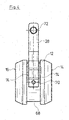
- eine Seitenansicht einer ersten Ausführungsform eines Absperrkörpers mit einem anschließenden Schwenkarm,
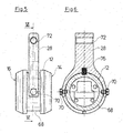
- Fig.5:
- eine Seitenansicht einer zweiten Ausgestaltung des Absperrkörpers mit anschließendem Schwenkarm, und
- Fig. 6:
- eine Schnittansicht der Anordnung in
Figur 5 entlang der Linie VI-VI inFigur 5 .
- Fig. 1:
- a shuttle valve according to the invention in a first closed position,
- Fig. 2:
- the shuttle valve after
Fig. 1 in a second closed position, - Fig. 3:
- an enlarged sub-area
Fig. 1 , - Fig. 4:
- a side view of a first embodiment of a shut-off body with an adjoining swivel arm,
- Fig. 5:
- a side view of a second embodiment of the shut-off body with a subsequent pivot arm, and
- Fig. 6:
- a sectional view of the arrangement in
Figure 5 along the line VI-VI inFigure 5 .
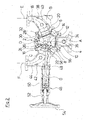
Das in den
In einem Innenraum 10 des Ventilgehäuses 2, durch welchen die Strömungspfade von dem Fluideinlass 4 zu den beiden Fluidauslässen 6 und 8 verlaufen, ist ein Absperrkörper 12 angeordnet, mit welchem wahlweise bzw. abwechselnd jeweils einer der Fluidauslässe 6 und 8 verschließbar ist. Zum Verschließen der Fluidauslässe 6 und 8 weist der Absperrkörper 12 an voneinander direkt abgewandten Seiten zwei, an ihrem Außenrand konisch angefaste Dichtflächen 14 und 16 auf, wobei die erste Dichtfläche 14 in einer ersten Schließstellung des Absperrkörpers 12, in welcher dieser den ersten Fluidauslass 6 verschließt, an einem ersten Ventilsitz 18 fluiddicht zur Anlage kommt, der an einer außenseitig des ersten Fluidauslasses 6 angeordneten und in das Ventilgehäuse 2 eingreifenden Ringhülse 20 ausgebildet ist (
Der Absperrkörper 12 ist in seine zwei Schließstellungen schwenkbar. Hierzu ist an einer die Dichtflächen 14 und 16 verbindenden Umfangswandung 26 des Absperrkörpers 12 ein Schwenkarm 28 angeordnet, welcher sich in Richtung normal zu der Umfangswandung 26 erstreckt. Der Schwenkarm 28 ist im Bereich seines von dem Absperrkörper 12 abgewandten Endes an einem Gelenkstift 30 angelenkt, welcher eine Schwenkachse D des Absperrkörpers 12 bildet. Der Gelenkstift 30 und somit auch die Schwenkachse D des Absperrkörpers 12 sind in dem Ventilgehäuse 2 auf der Mittelachse A des Fluideinlasses 4 liegend in einem Bereich 32 angeordnet, welcher außerhalb der Strömungspfade von dem Fluideinlass 4 zu den Fluidauslässen 6 und 8 gelegen ist. Die Schwenkachse D ist an einer dem Fluidauslass 4 abgewandten Seite im Inneren des Ventilgehäuses 2 gelegen. Die Ausrichtung des Gelenkstifts 30 und der Schwenkachse D ist hierbei normal zu der Mittelachse A des Fluideinlasses und normal zu einer von den Mittelachsen B und C der Fluidauslässe 6 und 8 aufgespannten Ebene.The shut-off
An dem Ventilgehäuse 2 ist koaxial zu der Mittelachse A des Fluideinlasses 4 ein Anschlussstutzen 34 angeordnet. Der Anschlussstutzen 34 bildet einen Strömungspfad von einem in den Zeichnungen nicht dargestellten, mit einem Fluiddruck beaufschlagten Raum einer technischen Anlage zu dem Fluideinlass 4 des Ventilgehäuses 2, wobei sich ein den Strömungspfad bildendes Innenlumen 36 des Anschlussstutzens 34 von einem eingangsseitigen Querschnitt, welcher kleiner als der Querschnitt des Fluideinlasses 4 ist, kontinuierlich auf den Querschnitt des Fluideinlasses 4 vergrößert.A connecting
An den ersten Fluidauslass 6 schließt sich an dem Ventilgehäuse 2 ein Anschlussstutzen 38 an. Der Anschlussstutzen 38 weist ein Innenlumen 40 auf, dessen Querschnitt sich ausgehend von dem, dem Fluidauslass 6 zugewandten Ende des Anschlussstutzens 38, an welchem der Querschnitt des Innenlumens 40 mit dem Querschnitt des Fluidauslasses 6 korrespondiert, kontinuierlich verjüngt.A
An den zweiten Fluidauslass 8 angrenzend ist an dem Ventilgehäuse 2 ein weiterer Anschlussstutzen 42 angeordnet. Auch bei diesem Anschlussstutzen 42 verjüngt sich der Querschnitt eines Innenlumens 44 ausgehend von dem, dem Fluidauslass 8 zugewandten Ende des Anschlussstutzens 42, an welchem der Querschnitt des Innenlumens 44 mit dem Querschnitt des Fluidauslasses 6 korrespondiert, kontinuierlich auf einen kleineren Querschnitt.A further connecting
Sowohl der Anschlussstutzen 38 als auch der Anschlussstutzen 42 sind als Krümmer ausgebildet. Hierbei stimmt eine Mittelachse E des Innenlumens 40 des Anschlussstutzens 38 an dem Ende des Anschlussstutzens 38, welches dem ersten Fluidauslass 6 zugewandt ist, mit der Mittelachse B des Fluidauslasses 6 überein und verläuft an dem von dem Fluideinlass 6 abgewandten Ende des Anschlussstutzens 38 parallel zur Mittelachse A des Fluideinlasses. Eine Mittelachse F des Innenlumens 44 des Anschlussstutzens 42 stimmt an dem Ende des Anschlussstutzens 42, welches dem zweiten Fluidauslass 8 zugewandt ist, mit der Mittelachse C des Fluidauslasses 8 überein und verläuft an dem von dem Fluideinlass 8 abgewandten Ende des Anschlussstutzens 42 ebenfalls parallel zur Mittelachse A des Fluideinlasses. An den von dem Ventilgehäuse 2 abgewandten Enden der Anschlussstutzen 38 und 42 ist jeweils ein in den Zeichnungen ebenfalls nicht dargestelltes Sicherheitsventil angeordnet, mit denen wahlweise ein in dem an dem Anschlussstutzen 34 angeschlossenen Raum herrschender Überdruck abgebaut werden kann.Both the
Zum Schwenken des Absperrkörpers 12 in seine beiden Schließstellungen ist das dargestellte Wechselventil mit einem Linearantrieb 46 ausgestattet. Bei dem Linearantrieb 46 handelt es sich um einen handbetätigten Spindeltrieb. Dieser Spindeltrieb weist eine Gewindespindel 49 auf, welche mit einer Betätigungsstange 48 gekoppelt ist, welche durch eine Außenwandung des Anschlussstutzens 42 und den Fluideinlass 8 in den Innenraum 10 des Ventilgehäuses 2 geführt ist, wo sie mit dem Absperrkörper 12 bewegungsgekoppelt ist. Die Betätigungsstange 48 definiert eine Bewegungsachse G des Linearantriebs 46. Die Ausrichtung der Betätigungsstange 48 bzw. die Ausrichtung der Bewegungsachse G sind derart, dass sie sich quer zu der von dem Gelenkstift 30 gebildeten Schwenkachse D erstrecken. Außenseitig des Anschlussstutzens 42 sind die Betätigungsstange 48 sowie die Gewindespindel 49 durch ein dort angeordnetes Gehäuse 50 geführt, wobei an einem von dem Ventilgehäuse 2 abgewandten Ende des Gehäuses 50 eine in das Gehäuse 50 eingreifende drehbare Spindelmutter 52 des Spindeltriebs angeordnet ist. Zur manuellen Betätigung des Spindeltriebs ist die Spindelmutter 52 drehfest mit einem Handrad 54 verbunden.To pivot the shut-off
An ihrem in den Innenraum 10 des Ventilgehäuses 2 eingreifenden Ende ist die Betätigungsstange 48 gelenkig mit dem Absperrkörper 12 verbunden. Zur Bildung dieser Gelenkverbindung weist die Betätigungsstange 48 an ihrem in den Innenraum 10 des Ventilgehäuses 2 eingreifenden Ende einen Gelenkkopf 56 auf. Der Gelenkkopf 56 ist im Wesentlichen zylindrisch ausgebildet und weist einen Querschnitt auf, welcher größer als der Querschnitt einer Verbindung zu der Betätigungsstange 48 ist. Mit dem Gelenkkopf 56 greift die Betätigungsstange 48 in eine Ausnehmung 58 ein, welche an dem Absperrköper 12 an dessen Dichtfläche 16 mittig ausgebildet ist.At its end engaging in the
An der Ausnehmung 58 ist ein Absatz ausgebildet, welcher die Ausnehmung 58 in einen direkt an die Dichtfläche 16 angrenzenden Abschnitt 60 und einen sich an diesen Abschnitt in Richtung der Dichtfläche 14 anschließenden Abschnitt 62 unterteilt (
In den unmittelbar an die Dichtfläche 16 angrenzenden Abschnitt 60 der Ausnehmung 58 greift ein Einsatz 64 ein, durch welchen die Betätigungsstange 48 geführt ist. Der Einsatz 64 umgreift den Gelenkkopf 56 und hält diesen in der Ausnehmung 58. Eine Außenseite des Einsatzes 64 fluchtet hierbei mit der Dichtfläche 16 des Absperrkörpers 12. An einer von dieser Außenseite direkt abgewandten Außenseite des Einsatzes 64 ist eine Ausnehmung 66 ausgebildet, welche hinsichtlich ihrer Lage und Abmessungen mit dem der Dichtfläche 14 zugewandten Abschnitt 62 der Ausnehmung 58 im Wesentlichen korrespondiert. Dieser Abschnitt 62 der Ausnehmung 58 bildet zusammen mit der an dem Einsatz 64 ausgebildeten Ausnehmung 66 einen Aufnahmeraum für den an dem Ende der Betätigungsstange 48 angeordneten Gelenkkopf 56, welcher hierin in Richtung der Bewegungsachse G des Linearantriebs 46 formschlüssig festgelegt ist, hierbei aber eine Relativbewegung zwischen Betätigungsstange 48 und Gelenkkopf 56 und dem Absperrkörper 12 in Richtung quer zu der Schwenkachse D und quer zu der Bewegungsachse G des Linearantriebes 46 zulässt.An
Wie anhand der
Die
- 22
- VentilgehäuseValve body
- 44th
- FluideinlassFluid inlet
- 66th
- FluidauslassFluid outlet
- 88th
- FluidauslassFluid outlet
- 1010
- Innenrauminner space
- 1212
- AbsperrkörperShut-off device
- 1414th
- DichtflächeSealing surface
- 1616
- DichtflächeSealing surface
- 1818th
- VentilsitzValve seat
- 2020th
- RinghülseRing sleeve
- 2222nd
- VentilsitzValve seat
- 2424
- RinghülseRing sleeve
- 2626th
- UmfangswandungPerimeter wall
- 2828
- SchwenkarmSwivel arm
- 3030th
- GelenkstiftHinge pin
- 3232
- BereichArea
- 3434
- AnschlussstutzenConnection piece
- 3636
- InnenlumenInner lumen
- 3838
- AnschlussstutzenConnection piece
- 4040
- InnenlumenInner lumen
- 4242
- AnschlussstutzenConnection piece
- 4444
- InnenlumenInner lumen
- 4646
- Linearantrieblinear actuator
- 4848
- BetätigungsstangeOperating rod
- 4949
- GewindespindelThreaded spindle
- 5050
- Gehäusecasing
- 5252
- SpindelmutterSpindle nut
- 5454
- HandradHandwheel
- 5656
- GelenkkopfSwivel head
- 5858
- AusnehmungRecess
- 6060
- Abschnittsection
- 6262
- Abschnittsection
- 6464
- Einsatzcommitment
- 6666
- AusnehmungRecess
- 6868
- RingnutRing groove
- 7070
- Bolzenbolt
- 7272
- DurchgangslochThrough hole
- 74, 7674, 76
- FederelementeSpring elements
- AA.
- MittelachseCentral axis
- BB.
- MittelachseCentral axis
- CC.
- MittelachseCentral axis
- DD.
- SchwenkachseSwivel axis
- EE.
- MittelachseCentral axis
- FF.
- MittelachseCentral axis
- GG
- BewegungsachseAxis of motion
Claims (14)
- A shuttle valve for a safety valve arrangement, with a valve housing (2) comprising a fluid inlet (4) and two fluid outlets (6, 8), as well as with a movable shut-off body (12) which is arranged in the valve housing (2) and which can be moved between two closure positions, in which it closes one of the fluid outlets (6, 8), wherein the shut-off body (12) comprises two sealing surfaces (14, 16) which are away from one another, wherein a corresponding valve seat (18, 22) is formed on each of the fluid outlets (6, 8) in the valve housing (2), said valve seats being designed in a manner such that in one of the closure positions, one of the sealing surfaces (14, 16) is in sealing contact with one of the valve seats (18, 22), wherein
the shut-off body (12) is arranged in pivotable manner about a pivot axis (D) which is situated at the outer side of the shut-off body (12) and outside the sealing surfaces (14, 16) and the shuttle valve comprises a linear drive (46) which engages on the shut-off body (12) in a manner radially distanced to its pivot axis (D) and is coupled to the shut-off body (12) in a manner such that the shut-off body (12) is coupled in movement in a direct manner to a linearly movable part of the linear drive (46) and is pivotable between its closure positions by way of moving the linear drive (46). - A shuttle valve according to claim 1, characterised in that the linear drive (46) is a hand-actuated linear drive and in particular a hand-actuated spindle drive.
- A shuttle valve according to claim 1 or 2, characterised in that a movement axis (G) of the linear drive (46) extends transversely to the pivot axis (D).
- A shuttle valve according to one of the preceding claims, characterised in that the sealing surfaces and the valve seats are designed in a manner such that a purely metallic sealing pairing or a metallic- soft-sealing sealing pairing is given between the sealing surface and the associated valve seat.
- A shuttle valve according to one of the preceding claims, characterised in that the linear drive (46) engages on one of the sealing surfaces (22), preferably in its centre.
- A shuttle valve according to one of the preceding claims, characterised in that the pivot axis (D) of the shut-off body (12) is arranged in the shuttle valve outside the flow paths from the fluid inlet (4) to the fluid outlets (6, 8).
- A shuttle valve according to one of the preceding claims, characterised in that the shut-off body (12) is articulated on the pivot axis (D) via a pivot arm (28) which is arranged on the shut-off body (12) at the outer side.
- A shuttle valve according to claim 7, characterised in that the shut-off body (12) is movably connected, in particularly articulately connected to the pivot arm (28).
- A shuttle valve according to claim 8, characterised in that at least one spring element is arranged between the shut-off body (12) and the pivot arm (28) in a manner such that the shut-off body (12) is held in a defined idle position when it is not located in one of the closure positions.
- A shuttle valve according to one of the preceding claims, characterised in that the pivot axis (D) is defined by an jointed articulation of the shut-off body (12) which is situated in the inside of the valve housing (2).
- A shuttle valve according to one of the preceding claims, characterised in that the linear drive (46) is coupled to the shut-off body (12) by a joint connection and that the joint connection is preferably designed such that it permits a relative movement between the linear drive (46) and the shut-off body (12) in a direction transverse to the pivot axis (D) and transverse to the movement axis (G) of the linear drive (46).
- A shuttle valve according to claim 11, characterised in that the joint connection comprises a joint head (56) which is arranged on the linear drive (46) and which in a recess (58) in the shut-off body (12) is guided in a rotationally movable manner and in a linearly movable manner transversely to the pivot axis (D), wherein preferably the joint head (56) of the linear drive (46) is positively held by an insert (64) in a recess (58) of the shut-off body (12) in a manner such that a relative movement between the shut-off body (12) and the joint head (56) is possible transverse to the movement axis of the linear drive.
- A shuttle valve according to one of the preceding claims, characterised in that a linearly movable part of the linear drive (46) is led through one of the fluid outlets (8).
- A safety valve arrangement, with a shuttle valve and two safety valves arranged at the outlet side of the shuttle valve, characterised in that the shuttle valve is a shuttle valve according to one of the preceding claims, concerning which the two safety valves are each connected to a fluid outlet (6, 8).
Priority Applications (5)
| Application Number | Priority Date | Filing Date | Title |
|---|---|---|---|
| EP16166392.7A EP3236121B1 (en) | 2016-04-21 | 2016-04-21 | Shuttle valve for a safety valve apparatus and safety valve apparatus |
| BR102017008090-0A BR102017008090B1 (en) | 2016-04-21 | 2017-04-19 | SWITCH VALVE FOR A SAFETY VALVE ARRANGEMENT |
| US15/492,546 US10260645B2 (en) | 2016-04-21 | 2017-04-20 | Shuttle valve for a safety valve arrangement and safety valve arrangement |
| RU2017113683A RU2687390C2 (en) | 2016-04-21 | 2017-04-20 | Switch valve for system of safety valves and system of safety valves |
| CN201710264595.5A CN107314126B (en) | 2016-04-21 | 2017-04-21 | Reversing valve for a safety valve device and safety valve device |
Applications Claiming Priority (1)
| Application Number | Priority Date | Filing Date | Title |
|---|---|---|---|
| EP16166392.7A EP3236121B1 (en) | 2016-04-21 | 2016-04-21 | Shuttle valve for a safety valve apparatus and safety valve apparatus |
Publications (2)
| Publication Number | Publication Date |
|---|---|
| EP3236121A1 EP3236121A1 (en) | 2017-10-25 |
| EP3236121B1 true EP3236121B1 (en) | 2020-09-16 |
Family
ID=55808427
Family Applications (1)
| Application Number | Title | Priority Date | Filing Date |
|---|---|---|---|
| EP16166392.7A Active EP3236121B1 (en) | 2016-04-21 | 2016-04-21 | Shuttle valve for a safety valve apparatus and safety valve apparatus |
Country Status (4)
| Country | Link |
|---|---|
| US (1) | US10260645B2 (en) |
| EP (1) | EP3236121B1 (en) |
| CN (1) | CN107314126B (en) |
| RU (1) | RU2687390C2 (en) |
Families Citing this family (3)
| Publication number | Priority date | Publication date | Assignee | Title |
|---|---|---|---|---|
| US10591071B2 (en) * | 2017-10-09 | 2020-03-17 | Cyrus Shank Corporation | Manifolds for pressure relief systems |
| US11346453B2 (en) * | 2019-03-03 | 2022-05-31 | California Controlled Atmosphere | Switching assembly for pressure relief valves |
| CN113252325B (en) * | 2021-05-08 | 2022-11-11 | 重庆红江机械有限责任公司 | Gas flow measuring device |
Family Cites Families (17)
| Publication number | Priority date | Publication date | Assignee | Title |
|---|---|---|---|---|
| US2720214A (en) * | 1953-02-19 | 1955-10-11 | Bastian Blessing Co | Relief valve manifold |
| US2852947A (en) * | 1956-06-28 | 1958-09-23 | Karl A Klingler | Two way valve actuating mechanism |
| US3080884A (en) * | 1959-09-28 | 1963-03-12 | Eskimo Pie Corp | Distributor valve |
| US3605811A (en) * | 1968-11-14 | 1971-09-20 | United Aircraft Corp | Controlled impedance diverter valve |
| US4730355A (en) * | 1986-05-08 | 1988-03-15 | Kreinbihl Mark L | Pneumatic wave generator employing four-way valve arrangement |
| DE3700219A1 (en) * | 1987-01-07 | 1988-07-21 | Teves Gmbh Alfred | ELECTROMAGNETICALLY OPERABLE 3/2-WAY VALVE |
| FR2609518B1 (en) * | 1987-01-12 | 1990-12-28 | Abx Sa | SINGLE-MEMBRANE SWITCHING MICROELECTROVALVE |
| EP0343510A1 (en) * | 1988-05-23 | 1989-11-29 | Dirk Bastenhof | Pneumatic wave-generator for a swimming pool |
| US4979244A (en) * | 1988-05-23 | 1990-12-25 | Dirk Bastenhof | Wave valve |
| ITTO20030553A1 (en) * | 2003-07-17 | 2005-01-18 | Fiat Ricerche | FLUIDO FLOW CONTROL DEVICE |
| CN2619110Y (en) * | 2003-07-24 | 2004-06-02 | 吴道洪 | Small rotary three-way change-over valve |
| RU69606U1 (en) | 2006-04-17 | 2007-12-27 | Генрих Семенович Фалькевич | SWITCHING VALVE DEVICE |
| CN101101069B (en) * | 2006-07-04 | 2010-12-22 | 深圳迈瑞生物医疗电子股份有限公司 | Minitype valve |
| CN101769387B (en) * | 2009-11-23 | 2011-12-21 | 深圳大学 | Reversing valve with flow guide structure |
| RU151614U1 (en) | 2013-04-30 | 2015-04-10 | Открытое акционерное общество "Конструкторское бюро химавтоматики" | VALVE |
| US9377119B2 (en) * | 2013-08-30 | 2016-06-28 | Flextronics Automotive, Inc. | Solenoid actuated butterfly valve |
| DE102014106010A1 (en) * | 2014-04-29 | 2015-10-29 | Sig Technology Ag | Device for controlling or regulating the flow rate and / or flow direction of fluids |
-
2016
- 2016-04-21 EP EP16166392.7A patent/EP3236121B1/en active Active
-
2017
- 2017-04-20 RU RU2017113683A patent/RU2687390C2/en active
- 2017-04-20 US US15/492,546 patent/US10260645B2/en active Active
- 2017-04-21 CN CN201710264595.5A patent/CN107314126B/en active Active
Non-Patent Citations (1)
| Title |
|---|
| None * |
Also Published As
| Publication number | Publication date |
|---|---|
| US20170307088A1 (en) | 2017-10-26 |
| BR102017008090A2 (en) | 2017-10-24 |
| US10260645B2 (en) | 2019-04-16 |
| EP3236121A1 (en) | 2017-10-25 |
| RU2687390C2 (en) | 2019-05-13 |
| RU2017113683A3 (en) | 2018-10-23 |
| CN107314126A (en) | 2017-11-03 |
| RU2017113683A (en) | 2018-10-23 |
| CN107314126B (en) | 2020-07-03 |
Similar Documents
| Publication | Publication Date | Title |
|---|---|---|
| DE2645968C3 (en) | Valve coupling for large quantities of fluid | |
| EP1688654B1 (en) | Vacuum valve | |
| EP2780614A1 (en) | Actuating device for a rotatable closure part of a valve | |
| DE102012209629B4 (en) | Receiving part of a dry clutch | |
| DE2457230C3 (en) | Valve for shutting off and controlling high-temperature flow media | |
| EP3485192B1 (en) | Locking coupling | |
| EP3137795B1 (en) | Device for controlling or regulating the flow rate and/or flow direction of fluids | |
| EP3236121B1 (en) | Shuttle valve for a safety valve apparatus and safety valve apparatus | |
| EP1506361A1 (en) | Shut-off fitting | |
| EP1926930A1 (en) | Coupling device for connecting line devices, preferably quick connector | |
| AT502719B1 (en) | PINCH | |
| DE102017122757B4 (en) | Press tool for pressing fittings for the production of pipe connections and method for pressing fittings | |
| EP2348242B9 (en) | A coupling forming a dry coupling for sealed connection of supply channels transporting fluid or gaseous media | |
| EP2352938B1 (en) | Disk valve with leak prevention | |
| DE102010033429A1 (en) | Industrial robot has robot base, carrier element for support of grip arm or tool and multiple control arms with upper arm section and lower arm section in each case | |
| EP2212608B1 (en) | Coupling apparatus for the sealing connection of lines which transport liquid or gaseous media | |
| DE102008024363B4 (en) | stopcock | |
| EP1926929B1 (en) | Valve device | |
| EP1258662B1 (en) | Device for shutting off a fluid flow in a pipeline by a a ball-shaped shut-off member | |
| DE2035569B2 (en) | LOCKING VALVE WITH SMOOTH HOUSING PUSH AND MOVABLE, PRESSABLE SHUT-OFF PLATES | |
| EP2400190B1 (en) | Rotary plug valve | |
| EP0218792B1 (en) | Ball valve | |
| DE10305724B4 (en) | radiator connection | |
| DE1550181C (en) | Shut-off device, especially valve | |
| DE102010053117A1 (en) | Rotary plug valve for controlling flow of liquid/gas in pipeline, has spherical calotte coupled with rotary element via adjustable and lockable joint connection, to obtain spherical and axis-parallel movement of calotte |
Legal Events
| Date | Code | Title | Description |
|---|---|---|---|
| PUAI | Public reference made under article 153(3) epc to a published international application that has entered the european phase |
Free format text: ORIGINAL CODE: 0009012 |
|
| STAA | Information on the status of an ep patent application or granted ep patent |
Free format text: STATUS: THE APPLICATION HAS BEEN PUBLISHED |
|
| AK | Designated contracting states |
Kind code of ref document: A1 Designated state(s): AL AT BE BG CH CY CZ DE DK EE ES FI FR GB GR HR HU IE IS IT LI LT LU LV MC MK MT NL NO PL PT RO RS SE SI SK SM TR |
|
| AX | Request for extension of the european patent |
Extension state: BA ME |
|
| STAA | Information on the status of an ep patent application or granted ep patent |
Free format text: STATUS: REQUEST FOR EXAMINATION WAS MADE |
|
| 17P | Request for examination filed |
Effective date: 20180228 |
|
| RBV | Designated contracting states (corrected) |
Designated state(s): AL AT BE BG CH CY CZ DE DK EE ES FI FR GB GR HR HU IE IS IT LI LT LU LV MC MK MT NL NO PL PT RO RS SE SI SK SM TR |
|
| STAA | Information on the status of an ep patent application or granted ep patent |
Free format text: STATUS: EXAMINATION IS IN PROGRESS |
|
| 17Q | First examination report despatched |
Effective date: 20190503 |
|
| GRAP | Despatch of communication of intention to grant a patent |
Free format text: ORIGINAL CODE: EPIDOSNIGR1 |
|
| STAA | Information on the status of an ep patent application or granted ep patent |
Free format text: STATUS: GRANT OF PATENT IS INTENDED |
|
| INTG | Intention to grant announced |
Effective date: 20200518 |
|
| GRAS | Grant fee paid |
Free format text: ORIGINAL CODE: EPIDOSNIGR3 |
|
| GRAA | (expected) grant |
Free format text: ORIGINAL CODE: 0009210 |
|
| STAA | Information on the status of an ep patent application or granted ep patent |
Free format text: STATUS: THE PATENT HAS BEEN GRANTED |
|
| AK | Designated contracting states |
Kind code of ref document: B1 Designated state(s): AL AT BE BG CH CY CZ DE DK EE ES FI FR GB GR HR HU IE IS IT LI LT LU LV MC MK MT NL NO PL PT RO RS SE SI SK SM TR |
|
| REG | Reference to a national code |
Ref country code: GB Ref legal event code: FG4D Free format text: NOT ENGLISH |
|
| REG | Reference to a national code |
Ref country code: CH Ref legal event code: EP |
|
| REG | Reference to a national code |
Ref country code: DE Ref legal event code: R096 Ref document number: 502016011159 Country of ref document: DE |
|
| REG | Reference to a national code |
Ref country code: IE Ref legal event code: FG4D Free format text: LANGUAGE OF EP DOCUMENT: GERMAN |
|
| REG | Reference to a national code |
Ref country code: AT Ref legal event code: REF Ref document number: 1314459 Country of ref document: AT Kind code of ref document: T Effective date: 20201015 |
|
| PG25 | Lapsed in a contracting state [announced via postgrant information from national office to epo] |
Ref country code: HR Free format text: LAPSE BECAUSE OF FAILURE TO SUBMIT A TRANSLATION OF THE DESCRIPTION OR TO PAY THE FEE WITHIN THE PRESCRIBED TIME-LIMIT Effective date: 20200916 Ref country code: SE Free format text: LAPSE BECAUSE OF FAILURE TO SUBMIT A TRANSLATION OF THE DESCRIPTION OR TO PAY THE FEE WITHIN THE PRESCRIBED TIME-LIMIT Effective date: 20200916 Ref country code: BG Free format text: LAPSE BECAUSE OF FAILURE TO SUBMIT A TRANSLATION OF THE DESCRIPTION OR TO PAY THE FEE WITHIN THE PRESCRIBED TIME-LIMIT Effective date: 20201216 Ref country code: FI Free format text: LAPSE BECAUSE OF FAILURE TO SUBMIT A TRANSLATION OF THE DESCRIPTION OR TO PAY THE FEE WITHIN THE PRESCRIBED TIME-LIMIT Effective date: 20200916 Ref country code: GR Free format text: LAPSE BECAUSE OF FAILURE TO SUBMIT A TRANSLATION OF THE DESCRIPTION OR TO PAY THE FEE WITHIN THE PRESCRIBED TIME-LIMIT Effective date: 20201217 Ref country code: NO Free format text: LAPSE BECAUSE OF FAILURE TO SUBMIT A TRANSLATION OF THE DESCRIPTION OR TO PAY THE FEE WITHIN THE PRESCRIBED TIME-LIMIT Effective date: 20201216 |
|
| REG | Reference to a national code |
Ref country code: NL Ref legal event code: MP Effective date: 20200916 |
|
| PG25 | Lapsed in a contracting state [announced via postgrant information from national office to epo] |
Ref country code: LV Free format text: LAPSE BECAUSE OF FAILURE TO SUBMIT A TRANSLATION OF THE DESCRIPTION OR TO PAY THE FEE WITHIN THE PRESCRIBED TIME-LIMIT Effective date: 20200916 Ref country code: RS Free format text: LAPSE BECAUSE OF FAILURE TO SUBMIT A TRANSLATION OF THE DESCRIPTION OR TO PAY THE FEE WITHIN THE PRESCRIBED TIME-LIMIT Effective date: 20200916 |
|
| REG | Reference to a national code |
Ref country code: LT Ref legal event code: MG4D |
|
| PG25 | Lapsed in a contracting state [announced via postgrant information from national office to epo] |
Ref country code: CZ Free format text: LAPSE BECAUSE OF FAILURE TO SUBMIT A TRANSLATION OF THE DESCRIPTION OR TO PAY THE FEE WITHIN THE PRESCRIBED TIME-LIMIT Effective date: 20200916 Ref country code: RO Free format text: LAPSE BECAUSE OF FAILURE TO SUBMIT A TRANSLATION OF THE DESCRIPTION OR TO PAY THE FEE WITHIN THE PRESCRIBED TIME-LIMIT Effective date: 20200916 Ref country code: PT Free format text: LAPSE BECAUSE OF FAILURE TO SUBMIT A TRANSLATION OF THE DESCRIPTION OR TO PAY THE FEE WITHIN THE PRESCRIBED TIME-LIMIT Effective date: 20210118 Ref country code: SM Free format text: LAPSE BECAUSE OF FAILURE TO SUBMIT A TRANSLATION OF THE DESCRIPTION OR TO PAY THE FEE WITHIN THE PRESCRIBED TIME-LIMIT Effective date: 20200916 Ref country code: EE Free format text: LAPSE BECAUSE OF FAILURE TO SUBMIT A TRANSLATION OF THE DESCRIPTION OR TO PAY THE FEE WITHIN THE PRESCRIBED TIME-LIMIT Effective date: 20200916 Ref country code: LT Free format text: LAPSE BECAUSE OF FAILURE TO SUBMIT A TRANSLATION OF THE DESCRIPTION OR TO PAY THE FEE WITHIN THE PRESCRIBED TIME-LIMIT Effective date: 20200916 |
|
| PG25 | Lapsed in a contracting state [announced via postgrant information from national office to epo] |
Ref country code: ES Free format text: LAPSE BECAUSE OF FAILURE TO SUBMIT A TRANSLATION OF THE DESCRIPTION OR TO PAY THE FEE WITHIN THE PRESCRIBED TIME-LIMIT Effective date: 20200916 Ref country code: AL Free format text: LAPSE BECAUSE OF FAILURE TO SUBMIT A TRANSLATION OF THE DESCRIPTION OR TO PAY THE FEE WITHIN THE PRESCRIBED TIME-LIMIT Effective date: 20200916 Ref country code: IS Free format text: LAPSE BECAUSE OF FAILURE TO SUBMIT A TRANSLATION OF THE DESCRIPTION OR TO PAY THE FEE WITHIN THE PRESCRIBED TIME-LIMIT Effective date: 20210116 Ref country code: PL Free format text: LAPSE BECAUSE OF FAILURE TO SUBMIT A TRANSLATION OF THE DESCRIPTION OR TO PAY THE FEE WITHIN THE PRESCRIBED TIME-LIMIT Effective date: 20200916 |
|
| REG | Reference to a national code |
Ref country code: DE Ref legal event code: R097 Ref document number: 502016011159 Country of ref document: DE |
|
| PG25 | Lapsed in a contracting state [announced via postgrant information from national office to epo] |
Ref country code: SK Free format text: LAPSE BECAUSE OF FAILURE TO SUBMIT A TRANSLATION OF THE DESCRIPTION OR TO PAY THE FEE WITHIN THE PRESCRIBED TIME-LIMIT Effective date: 20200916 |
|
| PLBE | No opposition filed within time limit |
Free format text: ORIGINAL CODE: 0009261 |
|
| STAA | Information on the status of an ep patent application or granted ep patent |
Free format text: STATUS: NO OPPOSITION FILED WITHIN TIME LIMIT |
|
| 26N | No opposition filed |
Effective date: 20210617 |
|
| PG25 | Lapsed in a contracting state [announced via postgrant information from national office to epo] |
Ref country code: DK Free format text: LAPSE BECAUSE OF FAILURE TO SUBMIT A TRANSLATION OF THE DESCRIPTION OR TO PAY THE FEE WITHIN THE PRESCRIBED TIME-LIMIT Effective date: 20200916 Ref country code: SI Free format text: LAPSE BECAUSE OF FAILURE TO SUBMIT A TRANSLATION OF THE DESCRIPTION OR TO PAY THE FEE WITHIN THE PRESCRIBED TIME-LIMIT Effective date: 20200916 |
|
| PG25 | Lapsed in a contracting state [announced via postgrant information from national office to epo] |
Ref country code: MC Free format text: LAPSE BECAUSE OF FAILURE TO SUBMIT A TRANSLATION OF THE DESCRIPTION OR TO PAY THE FEE WITHIN THE PRESCRIBED TIME-LIMIT Effective date: 20200916 |
|
| PG25 | Lapsed in a contracting state [announced via postgrant information from national office to epo] |
Ref country code: LU Free format text: LAPSE BECAUSE OF NON-PAYMENT OF DUE FEES Effective date: 20210421 |
|
| REG | Reference to a national code |
Ref country code: BE Ref legal event code: MM Effective date: 20210430 |
|
| PG25 | Lapsed in a contracting state [announced via postgrant information from national office to epo] |
Ref country code: CH Free format text: LAPSE BECAUSE OF NON-PAYMENT OF DUE FEES Effective date: 20210430 Ref country code: LI Free format text: LAPSE BECAUSE OF NON-PAYMENT OF DUE FEES Effective date: 20210430 |
|
| PG25 | Lapsed in a contracting state [announced via postgrant information from national office to epo] |
Ref country code: IE Free format text: LAPSE BECAUSE OF NON-PAYMENT OF DUE FEES Effective date: 20210421 |
|
| PG25 | Lapsed in a contracting state [announced via postgrant information from national office to epo] |
Ref country code: IS Free format text: LAPSE BECAUSE OF FAILURE TO SUBMIT A TRANSLATION OF THE DESCRIPTION OR TO PAY THE FEE WITHIN THE PRESCRIBED TIME-LIMIT Effective date: 20210116 |
|
| REG | Reference to a national code |
Ref country code: AT Ref legal event code: MM01 Ref document number: 1314459 Country of ref document: AT Kind code of ref document: T Effective date: 20210421 |
|
| PG25 | Lapsed in a contracting state [announced via postgrant information from national office to epo] |
Ref country code: BE Free format text: LAPSE BECAUSE OF NON-PAYMENT OF DUE FEES Effective date: 20210430 |
|
| PG25 | Lapsed in a contracting state [announced via postgrant information from national office to epo] |
Ref country code: AT Free format text: LAPSE BECAUSE OF NON-PAYMENT OF DUE FEES Effective date: 20210421 |
|
| PG25 | Lapsed in a contracting state [announced via postgrant information from national office to epo] |
Ref country code: HU Free format text: LAPSE BECAUSE OF FAILURE TO SUBMIT A TRANSLATION OF THE DESCRIPTION OR TO PAY THE FEE WITHIN THE PRESCRIBED TIME-LIMIT; INVALID AB INITIO Effective date: 20160421 |
|
| PG25 | Lapsed in a contracting state [announced via postgrant information from national office to epo] |
Ref country code: NL Free format text: LAPSE BECAUSE OF NON-PAYMENT OF DUE FEES Effective date: 20200923 Ref country code: CY Free format text: LAPSE BECAUSE OF FAILURE TO SUBMIT A TRANSLATION OF THE DESCRIPTION OR TO PAY THE FEE WITHIN THE PRESCRIBED TIME-LIMIT Effective date: 20200916 |
|
| PGFP | Annual fee paid to national office [announced via postgrant information from national office to epo] |
Ref country code: IT Payment date: 20230428 Year of fee payment: 8 Ref country code: FR Payment date: 20230417 Year of fee payment: 8 Ref country code: DE Payment date: 20230421 Year of fee payment: 8 |
|
| PGFP | Annual fee paid to national office [announced via postgrant information from national office to epo] |
Ref country code: GB Payment date: 20230420 Year of fee payment: 8 |