EP1923280A1 - Capteur photosensible dans le domaine automobile - Google Patents
Capteur photosensible dans le domaine automobile Download PDFInfo
- Publication number
- EP1923280A1 EP1923280A1 EP07119750A EP07119750A EP1923280A1 EP 1923280 A1 EP1923280 A1 EP 1923280A1 EP 07119750 A EP07119750 A EP 07119750A EP 07119750 A EP07119750 A EP 07119750A EP 1923280 A1 EP1923280 A1 EP 1923280A1
- Authority
- EP
- European Patent Office
- Prior art keywords
- sensor
- zone
- lens
- objective
- optical element
- Prior art date
- Legal status (The legal status is an assumption and is not a legal conclusion. Google has not performed a legal analysis and makes no representation as to the accuracy of the status listed.)
- Granted
Links
Images

Classifications
-
- B—PERFORMING OPERATIONS; TRANSPORTING
- B60—VEHICLES IN GENERAL
- B60S—SERVICING, CLEANING, REPAIRING, SUPPORTING, LIFTING, OR MANOEUVRING OF VEHICLES, NOT OTHERWISE PROVIDED FOR
- B60S1/00—Cleaning of vehicles
- B60S1/02—Cleaning windscreens, windows or optical devices
- B60S1/04—Wipers or the like, e.g. scrapers
- B60S1/06—Wipers or the like, e.g. scrapers characterised by the drive
- B60S1/08—Wipers or the like, e.g. scrapers characterised by the drive electrically driven
- B60S1/0818—Wipers or the like, e.g. scrapers characterised by the drive electrically driven including control systems responsive to external conditions, e.g. by detection of moisture, dirt or the like
- B60S1/0822—Wipers or the like, e.g. scrapers characterised by the drive electrically driven including control systems responsive to external conditions, e.g. by detection of moisture, dirt or the like characterized by the arrangement or type of detection means
-
- B—PERFORMING OPERATIONS; TRANSPORTING
- B60—VEHICLES IN GENERAL
- B60R—VEHICLES, VEHICLE FITTINGS, OR VEHICLE PARTS, NOT OTHERWISE PROVIDED FOR
- B60R11/00—Arrangements for holding or mounting articles, not otherwise provided for
- B60R11/04—Mounting of cameras operative during drive; Arrangement of controls thereof relative to the vehicle
-
- B—PERFORMING OPERATIONS; TRANSPORTING
- B60—VEHICLES IN GENERAL
- B60S—SERVICING, CLEANING, REPAIRING, SUPPORTING, LIFTING, OR MANOEUVRING OF VEHICLES, NOT OTHERWISE PROVIDED FOR
- B60S1/00—Cleaning of vehicles
- B60S1/02—Cleaning windscreens, windows or optical devices
- B60S1/04—Wipers or the like, e.g. scrapers
- B60S1/06—Wipers or the like, e.g. scrapers characterised by the drive
- B60S1/08—Wipers or the like, e.g. scrapers characterised by the drive electrically driven
- B60S1/0818—Wipers or the like, e.g. scrapers characterised by the drive electrically driven including control systems responsive to external conditions, e.g. by detection of moisture, dirt or the like
- B60S1/0822—Wipers or the like, e.g. scrapers characterised by the drive electrically driven including control systems responsive to external conditions, e.g. by detection of moisture, dirt or the like characterized by the arrangement or type of detection means
- B60S1/0833—Optical rain sensor
- B60S1/0844—Optical rain sensor including a camera
-
- G—PHYSICS
- G01—MEASURING; TESTING
- G01N—INVESTIGATING OR ANALYSING MATERIALS BY DETERMINING THEIR CHEMICAL OR PHYSICAL PROPERTIES
- G01N21/00—Investigating or analysing materials by the use of optical means, i.e. using sub-millimetre waves, infrared, visible or ultraviolet light
- G01N21/84—Systems specially adapted for particular applications
- G01N21/88—Investigating the presence of flaws or contamination
- G01N21/95—Investigating the presence of flaws or contamination characterised by the material or shape of the object to be examined
- G01N21/958—Inspecting transparent materials or objects, e.g. windscreens
-
- G—PHYSICS
- G03—PHOTOGRAPHY; CINEMATOGRAPHY; ANALOGOUS TECHNIQUES USING WAVES OTHER THAN OPTICAL WAVES; ELECTROGRAPHY; HOLOGRAPHY
- G03B—APPARATUS OR ARRANGEMENTS FOR TAKING PHOTOGRAPHS OR FOR PROJECTING OR VIEWING THEM; APPARATUS OR ARRANGEMENTS EMPLOYING ANALOGOUS TECHNIQUES USING WAVES OTHER THAN OPTICAL WAVES; ACCESSORIES THEREFOR
- G03B29/00—Combinations of cameras, projectors or photographic printing apparatus with non-photographic non-optical apparatus, e.g. clocks or weapons; Cameras having the shape of other objects
-
- G—PHYSICS
- G06—COMPUTING OR CALCULATING; COUNTING
- G06V—IMAGE OR VIDEO RECOGNITION OR UNDERSTANDING
- G06V20/00—Scenes; Scene-specific elements
- G06V20/50—Context or environment of the image
- G06V20/56—Context or environment of the image exterior to a vehicle by using sensors mounted on the vehicle
-
- B—PERFORMING OPERATIONS; TRANSPORTING
- B60—VEHICLES IN GENERAL
- B60R—VEHICLES, VEHICLE FITTINGS, OR VEHICLE PARTS, NOT OTHERWISE PROVIDED FOR
- B60R11/00—Arrangements for holding or mounting articles, not otherwise provided for
- B60R2011/0001—Arrangements for holding or mounting articles, not otherwise provided for characterised by position
- B60R2011/0003—Arrangements for holding or mounting articles, not otherwise provided for characterised by position inside the vehicle
- B60R2011/0026—Windows, e.g. windscreen
Definitions
- the present invention relates to cameras equipped with sensors, for example of the CCD sensor type (charge coupled sensors), CMOS sensor (Complementary Metal Oxide Semiconductor) or video cameras type cameras.
- CCD sensor type charge coupled sensors
- CMOS sensor Complementary Metal Oxide Semiconductor
- video cameras type cameras These sensors will be grouped in the rest of this text under the generic term of photosensitive sensors. They provide representative image signals that can then be processed. They are generally sensitive in the visible and / or in the infrared, in particular in the near infrared.
- the images obtained can be processed to allow the display of images on screens, for example at the dashboard or projected on the windshield, in particular to alert the driver in case of danger or simply to improve his visibility .
- the images can also detect raindrops on the windshield.
- These sensors can be used during the day. They can also be used at night, so one can exploit their capabilities to detect infrared radiation. In night use, these sensors thus participate for example in the "night vision” (or “night vision” in English), where the images, once processed, are projected on a display screen generally in the form of images in black and white.
- the sensor is generally embedded in the vehicle near the windshield, for example about twenty centimeters from it, and is therefore associated with a focused optics on the windshield in order to accurately detect drops of water on the windshield -brise, their contours, their size ....
- a sensor to take images of the road, ie images in far field through the windshield, it is necessary this time to associate the sensor an optics focused to infinity.
- the purpose of the invention is therefore to remedy these drawbacks, in particular by proposing a new type of onboard sensor in a vehicle that can serve several applications satisfactorily.
- the invention firstly relates to a photosensitive sensor vis-à-vis at least a portion of the radiation in the visible and / or in the near-infrared, vehicle-mounted, said sensor being associated with an objective having a first zone which is focused at infinity and a second zone focused in near field.
- the "near field” is a term known to those skilled in the art, it relates here, in particular at a distance of the order of a centimeter or a few tens of centimeters (corresponding for example to a usual distance camera-zone wiped with windshield in the vehicle).
- the relative size of the first and second zones of the obective can be adapted as needed.
- majority andminority are meant the respective spatial extents of the lens areas that are focused differently.
- Majority means that the area of the lens that is focused at infinity (respectively near field) extends over more than 50% of the entrance surface of the lens placed in front of the sensor.
- the ratio between the surfaces of the two zones of the lens is about 50/50 or, more generally, in the range 70 / 30-60 / 40.
- the choice of the ratio will be made, in particular, depending on whether we want to promote the detection of near or far images, depending on the intended applications.
- the invention therefore proposes to use a multi-lens, in particular a bifocal lens, so that the on-board sensor can become multifunctional: methods of detection of lane edges, road edges, pedestrian detection or obstacles to be able to exploit the portions of images taken by the sensor, which are sufficiently clear thanks to the area of the lens focused to infinity. And a method of the automatic operation type wiper will be able to exploit the portion of images taken at a very short distance, on the windshield, through the area of the lens focused on the windshield.
- We can thus have an image which is the superposition of images taken in the distance with the adapted focal length, and images taken at close distance with a smaller focal length. It may be useful, optionally, to improve the contrast of at least one of the images or the image superimposition thus obtained (s) by a known treatment of the type of contrast enhancement.
- the objective comprises a plurality of optical elements of the lens type, in particular grouped into one or more lens trains in a known manner, including an optical element defining the zone and disposed in or substantially close to a pupil plane. opening of the lens.
- This particular arrangement ensures that any point of the far-field image (image of the road) on the one hand and that any point of the near-field image (image of the windshield) on the other hand is formed by an equivalent amount of rays (equivalent pupil portions of aperture).
- This optical element can be placed anywhere in the lens, which is usually a complex combination of lenses.
- Two configurations are envisaged, in particular: either it is the first optical element since the entry of the objective, or it is an optical element disposed just upstream.
- the face of the objective is referred to the image to be taken, thus to the outside, and "upstream” a provision in the front of the obfective relative to the image to detect.
- this optical element is a lens that is predominantly optically neutral and locally focused in the near field.
- This may include a lens with parallel input and output faces, and locally having a substantially at least partially convex exit face.
- this optical element is the first lens of the objective, the input lens thereof, the near-field focused area being obtained by a local modification of the curvature of the exit face of the lens. the lens, in particular with a convex portion different from the curvature of the remainder of the exit face.
- the modification may be in the form of a spherical or aspherical lens portion.
- the zone focused in the near field of the output face of the optical element is located in the central part of said element.
- the objective may be a lens train whose first lens is modified or associated with a modified lens, the lenses being all of substantially circular contour, and the modification being an area centered on the lens face considered, and protruding by relative to the curvature or the absence of curvature thereof.
- the sensor and its lens thus described can be used in a method of detecting raindrops on a windshield of the vehicle, but also for capturing images of road scenes through the windshield of the vehicle.
- the invention also relates to a method for detecting raindrops on a windshield using a photosensitive sensor vis-à-vis at least part of the radiation in the visible and / or in the near infra -red, said sensor being associated with an objective having a first major area which is focused to infinity and a second minority area with a shorter focal length.
- the invention also relates to an image processing device on board a motor vehicle, using at least one sensor as described above.
- the invention also relates to an image processing method, using the signals received by such a sensor embedded on a motor vehicle.
- the invention also relates to the motor vehicle equipped with such a sensor.
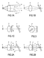
- Figure 1a shows a standard C sensor, of the CCD type, and associated with a lens O focused to infinity in order to capture images in the distance.
- Sensor and lens are arranged behind the wiped area of the windshield of a motor vehicle, about ten to twenty centimeters from it.
- the objective lens O comprises a lens train, it has been symbolized by a single lens O. Rays entering the lens have been traced to reach the receiving surface of the sensor C: The r1 rays are located at the top, r2 in middle part and r3 in the lower part of the image.
- Figure 1b adds to the previous figure the symbolic representation of a windshield P and a drop G on it. With such an objective, this drop of water G on the windshield is not correctly imaged on the sensor, and is therefore not detectable by image processing.
- an additional lens L1 which is predominantly optically neutral, is added according to the invention to the lens O, except in its central part where it has a zone Z2 focused in the near field, of shape at least partially convex: an objective is obtained with an infinitely focal zone Z1 "surrounding" a zone Z2 focused in the near field.
- FIG. 3 shows the exit face of the modified lens L1: the near-field focused zone Z2 is circular in shape, arranged on the circular exit face of the lens concentrically.
- the zone Z1 and the zone Z2 are of similar dimensions (when projected on a vertical plane according to the figure).
- the modified zone Z2 here is of convex shape, substantially spherical.
- the zone Z2 can be aspherical.
- this lens L1 is in an aperture pupil plane of the objective lens O.
- This lens does not modify the path of the rays imaging objects at a great distance, except in the center of the image.
- the rays that cross the lens in this central part Z2 are deflected in such a way that they no longer imitate the center of the image.
- the sensor-objective system according to the invention thus "looks" both at a distance and at a very short distance, the overall image being represented in FIG. 6 and being the sum of the images 4c and 5c. It is verified from FIG. 6 that the image obtained makes it possible to have a clear view of both the image of the road in the distance and drops of water on the windshield.
- An image processing of the type of contrast enhancement treatment is possible but optional.
- the invention therefore makes it possible to share the same camera, the same sensor for multiple functions, thanks to a modified lens. It is thus no longer necessary to have a sensor dedicated to the detection of rain.
- the invention thus finds application in the automotive field, but is also applicable in any other field where there is a need for a sensor that is effective from near and far, especially in any other type of locomotion means.
- the images obtained according to the invention can then be subjected to various treatments for their exploitation.
Landscapes
- Engineering & Computer Science (AREA)
- Mechanical Engineering (AREA)
- General Physics & Mathematics (AREA)
- Physics & Mathematics (AREA)
- Automation & Control Theory (AREA)
- General Health & Medical Sciences (AREA)
- Theoretical Computer Science (AREA)
- Health & Medical Sciences (AREA)
- Life Sciences & Earth Sciences (AREA)
- Chemical & Material Sciences (AREA)
- Analytical Chemistry (AREA)
- Biochemistry (AREA)
- Multimedia (AREA)
- Immunology (AREA)
- Pathology (AREA)
- Investigating Or Analysing Materials By Optical Means (AREA)
- Studio Devices (AREA)
- Air Bags (AREA)
- Vehicle Body Suspensions (AREA)
- Switches Operated By Changes In Physical Conditions (AREA)
- Organic Low-Molecular-Weight Compounds And Preparation Thereof (AREA)
- Optical Radar Systems And Details Thereof (AREA)
- Light Receiving Elements (AREA)
- Lenses (AREA)
- Photometry And Measurement Of Optical Pulse Characteristics (AREA)
- Measuring Pulse, Heart Rate, Blood Pressure Or Blood Flow (AREA)
Abstract
Description
- La présente invention concerne des caméras équipées de capteurs, par exemple du type capteur CCD (capteurs à couplage de charge), capteur CMOS (Complementary Metal Oxide Semiconductor) ou encore des caméras de type caméras vidéo. Ces capteurs seront regroupés dans la suite du présent texte sous le terme générique de capteurs photosensibles. Ils fournissent des signaux représentatifs d'image qui peuvent ensuite être traités. Ils sont généralement sensibles dans le visible et/ou dans l'infrarouge, notamment dans le proche infrarouge.
- On intègre de plus en plus fréquemment ce type de capteurs photosensibles dans des véhicules automobiles. Les images obtenues peuvent être traitées pour permettre l'affichage d'images sur des écrans, par exemple au niveau du tableau de bord ou en projection sur le pare-brise, notamment pour alerter le conducteur en cas de danger ou simplement pour améliorer sa visibilité. Les images peuvent aussi permettre de détecter des gouttes de pluie sur le pare-brise.
- Ces images peuvent participer au déclenchement automatique d'une fonctionnalité du véhicule (alerte au conducteur, déclenchement automatique de freinage, déclenchement automatique des essuie-glace en cas de visualisation de gouttes d'eau sur le pare-brise, avertissement visuel ou sonore, pilotage de certaines fonctions du projecteur ...).
- Ces capteurs peuvent être utilisés de jour. Ils peuvent aussi être utilisés de nuit, on peut alors exploiter leurs capacités à détecter les rayonnements dans l'infrarouge. En utilisation nocturne, ces capteurs participent ainsi par exemple à la fonctionnalité « vision de nuit » (ou « night vision » en anglais), où les images, une fois traitées, sont projetées sur un écran d'affichage généralement sous forme d'images en noir et blanc.
- On voit de ces applications très variées qu'il est souhaitable, mais très difficile en pratique, d'utiliser un seul capteur pour réaliser plusieurs de ces applications, car les paramètres de saisie des images varient considérablement selon les applications.
- Prenons une application intéressant particulièrement la présente invention, à savoir l'utilisation d'un capteur pour détecter des gouttes d'eau éventuelles sur le pare-brise du véhicule, ceci afin de piloter automatiquement le fonctionnement des essuie-glace : Le capteur est généralement embarqué dans le véhicule à proximité du pare-brise, à par exemple une vingtaine de centimètres de celui-ci, et il est donc associé à une optique focalisée sur le pare-brise afin de pouvoir détecter précisément les gouttes d'eau sur le pare-brise, leurs contours, leur taille .... Au contraire, si l'on veut utiliser un capteur pour prendre des images de la route, c'est à dire des images en champ lointain à travers le pare-brise, il faut cette fois associer au capteur une optique focalisée à l'infini.
- On en vient donc à utiliser des capteurs dédiés, un par application, ce qui augmente le coût, l'encombrement et la complexité des équipements du véhicule, l'encombrement n'étant pas le moindre des inconvénients car l'espace disponible à proximité du pare-brise est souvent très limité.
- L'invention a alors pour but de remédier à ces inconvénients, notamment en proposant un nouveau type de capteur embarqué dans un véhicule qui puisse servir à plusieurs applications de façon satisfaisante.
- L'invention a tout d'abord pour objet un capteur photosensible vis-à-vis d'au moins une partie du rayonnement dans le visible et/ou dans le proche infrarouge, embarqué sur véhicule, ledit capteur étant associé à un objectif présentant une première zone qui est focalisée à l'infini et une seconde zone focalisée en champ proche.
- Le « champ proche » est un terme connu de l'homme de l'art, il se raporte ici, notamment à une distance de l'ordre du centimètre ou de quelques dizaines de centimètres (correspondant par exemple à une distance habituelle caméra- zone essuyée de parebrise dans le véhicule).
- On peut adapter selon les besoins la taille relative des première et seconde zones de l'obectif.
- L'une peut ainsi avoir une surface majoritaire ou minoritaire par rapport à l'autre. On comprend par « majoritaire » et « minoritaire » les étendues spatiales respectives des zones de l'objectif focalisées différemment. « Majoritaire » signifie donc que la zone de l'objectif qui est focalisée à l'infini (respectivement à champ proche) s'étend sur plus de 50% de la surface d'entrée de l'objectif placé devant le capteur.
- Selon un mode de réalisation de l'invention, le ratio entre les surfaces des deux zones de l'objectif est d'environ 50/50 ou, plus généralement, dans la gamme 70/30-60/40. Le choix du ratio se fera, notamment, selon que l'on veut favoriser la détection d'images proches ou lointaines, selon les applications visées.
- L'invention propose donc d'utiliser un objectif multi-, notamment bifocal de façon à ce que le capteur embarqué puisse devenir multifonctions : des procédés de détection de bords de voie, de bords de route, de détection de piétons ou d'obstacles vont pouvoir exploiter les portions d'images prises par le capteur, suffisamment nettes grâce à la zone de l'objectif focalisé à l'infini. Et un procédé du type fonctionnement automatique des essuie glace va pouvoir exploiter la portion d' images prises à très courte distance, sur le pare-brise, à travers la zone de l'objectif focalisé sur le pare-brise. On peut avoir ainsi une image qui est la superposition d'images prises au loin avec la focale adaptée, et d'images prises à proche distance à focale plus petite. Il peut être utile, optionnellement, d'améliorer le contraste d'une au moins des images ou de la superposition d'images ainsi obtenue(s) par un traitement connu du type renforcement des contrastes.
- Avantageusement, l'objectif comporte une pluralité d'éléments optiques du type lentilles, notamment regroupées en un ou plusieurs trains de lentilles de façon connue, dont un élément optique définissant la zone et disposé dans ou substantiellement à proximité d'un plan de pupille d'ouverture de l'objectif. Cette disposition particulière garantit que tout point de l'image en champ lointain (image de la route) d'une part et que tout point de l'image en champ proche (image du pare-brise) d'autre part est formé par une quantité equivalente de rayons (portions de la pupille d'ouverture équivalentes).
- Cet élément optique, une fois cette condition remplie, peut être disposé à tout endroit de l'objectif, qui est généralement une combinaison complexe de lentilles. Deux configurations sont envisagées, notamment : soit c'est le premier élément optique depuis l'entrée de l'objectif, soit c'est un élément optique disposé juste en amont. On comprend par « entrée » de l'objectif la face de l'objectif tournée vers l'image à prendre, vers l'extérieur donc, et par « amont » un disposition à l'avant de l'obejctif par rapport à l'image à détecter.
- Selon un mode de réalisation, cet élément optique est une lentille majoritairement neutre sur le plan optique et localement focalisée en champ proche. Il peut s'agir notamment d'une lentille à faces d'entrée et de sortie parallèles, et présentant localement une face de sortie sensiblement au moins partiellement convexe.
- Selon un autre mode de réalisation, cet élément optique est la première lentille de l'objectif, la lentille d'entrée de celui-ci, la zone focalisée en champ proche étant obtenu par une modification locale de la courbure de la face de sortie de la lentille, notamment avec une partie convexe différente de la courbure du reste de la face de sortie.
- Dans un cas comme dans l'autre, la modification peut se présenter sous forme d'une portion de lentille sphérique ou asphérique.
- Avantageusement, la zone focalisée en champ proche de la face de sortie de l'élément optique est située dans la partie centrale dudit élément.
- Concrètement, l'objectif peut être un train de lentilles dont la première lentille est modifiée ou associée à une lentille modifiée, les lentilles étant toutes de contour sensiblement circulaire, et la modification étant une zone centrée sur la face de lentille considérée, et protubérante par rapport à la courbure ou l'absence de courbure de celle-ci.
- Le capteur et son objectif ainsi décrits peuvent être utilisé dans un procédé de détection de gouttes de pluie sur un pare-brise du véhicule, mais aussi pour la saisie d'images de scènes de la route à travers le pare-brise du véhicule.
- L'invention concerne aussi un procédé de détection de gouttes de pluie sur un pare-brise à l'aide d'un capteur photosensible vis-à-vis d'au moins une partie du rayonnement dans le visible et/ou dans le proche infra-rouge, ledit capteur étant associé à un objectif présentant une première zone majoritaire qui est focalisée à l'infini et une seconde zone minoritaire avec une focale plus courte.
- L'invention concerne aussi un dispositif de traitement d'images embarqué sur un véhicule automobile, utilisant au moins un capteur selon tel que décrit plus haut.
- L'invention concerne aussi un procédé de traitement d'images, utilisant les signaux reçus par un tel capteur embarqué sur un véhicule automobile.
- L'invention concerne aussi le véhicule automobile muni d'un tel capteur.
- L'invention sera détaillée ci-après avec des exemples non limitatifs, à l'aide des figures suivantes :
- fig.1a,1b,1c : une représentation schématique d'objectifs de capteur intéressant l'invention,
- fig. 2a,2b : une représentation schématique d'un capteur avec objectif modifié selon l'invention vu en coupe, selon que l'on considère une image d'une scène de route au loin (Fig.2a) ou d'une goutte d'eau sur le pare-brise (Fig.2b).,
- fig. 3 :une représentation de la lentille modifiée de l'objectif selon la figure précédente, vue de face et vue de côté,
- Fig. 4a,4b,4c : des images prises au loin selon l'invention,
- Fig. 5a,5b,5c : des images prises à courte distance selon l'invention,
- Fig. 6 : une image superposant une image prise au loin et prise à courte distance selon l'invention. Toutes ces figures sont extrêmement schématiques et ne respectent pas nécessairement l'échelle, pour plus de clarté.
- La figure 1a représente un capteur standard C, du type CCD, et associé à un objectif O focalisé à l'infini afin de saisir des images au loin. Capteur et objectif sont disposés derrière la zone essuyée du pare-brise d'un véhicule automobile, à environ une dizaine à une vingtaine de centimètres de celui-ci. L'objectif O comporte un train de lentilles, il a été symbolisé par une unique lentille O. On a tracé des rayons entrant dans l'objectif pour atteindre la surface réceptrice du capteur C : Les rayons r1 sont situés dans le haut, r2 en partie médiane et r3 en partie basse, de l'image.
- La figure 1b ajoute à la figure précédente la représentation symbolique d'un pare-brise P et d'une goutte G sur celui-ci. Avec un tel objectif, cette goutte d'eau G sur le pare-brise n'est pas correctement imagée sur le capteur, et n'est donc pas détectable par traitement d'images.
- Comme représenté à la figure 1c, on ajoute selon l'invention à l'objectif O une lentille supplémentaire L1, qui est majoritairement neutre sur le plan optique, sauf dans sa partie centrale où elle présente une zone Z2 focalisée en champ proche, de forme au moins partiellement convexe : on obtient un objectif avec une zone Z1 à focale à l'infini « entourant » une zone Z2 focalisée en champ proche.
- La figure 3 présente la face de sortie de la lentille modifiée L1 : la zone focalisée en champ proche Z2 est de forme circulaire, disposée sur la face de sortie circulaire de la lentille, de manière concentrique. Selon un exemple de réalisation, la zone Z1 et la zone Z2 sont de dimensions similaires (une fois projetées sur un plan vertical selon la figure). La zone Z2 modifiée est ici de forme convexe, substantiellement sphérique. Alternativement, la zone Z2 peut être asphérique.
- Comme représenté en figure 2a, cette lentille L1 se trouve dans un plan de pupille d'ouverture de l'objectif O. Cette lentille ne modifie pas le cheminement des rayons imageant des objets à grande distance, sauf au centre de l'image. Cependant, les rayons qui traversent l'objectif dans cette partie centrale Z2 sont déviés de telle manière qu'ils n'imagent plus le centre de l'image.
- Le résultat, représenté en figure 4c, est une image superposant :
- une image très nette de la scène de route, représentée en figure 4a (et correspondant aux rayons r4 passant à la périphérie comme représenté en figure 2a, c'est-à-dire traversant la zone Z1 à focale à l'infini)
- et une image très floue (correspondant aux rayons r5 passant au centre comme représenté en figure 2a, c'est-à-dire les rayons passant par la zone Z2 à focale réduite de la lentille L1).
- Venons-en maintenant à la goutte d'eau G : elle est bien imagée par les rayons traversant la zone Z2 de la lentille L1, ce sont les rayons r6 représentés en figure 2b. Son image est par contre très floue pour les rayons r7 passant par Z1 : ce sont les rayons r7 représentés en figure 2b.
- Le résultat, représenté en figure 5c, est une image superposant
- une image très nette de la goutte : figure 5a,
- et une image très floue : figure 5b.
- Le système capteur - objectif selon l'invention « regarde » ainsi à la fois au loin et à très courte distance, l'image globale étant représenté à la figure 6 et étant la somme des images 4c et 5c. On vérifie de la figure 6 que l'image obtenue permet une grande netteté à la fois de l'image de la route au loin et des gouttes d'eau sur le pare-brise.
- Un traitement d'image du type traitement de renforcement des contrastes est envisageable mais optionnel.
- L'invention permet donc bien de partager la même caméra, le même capteur pour de multiples fonctions, grâce à un objectif modifié. On n'est ainsi plus obligé d'avoir un capteur dédié à la détection de pluie.
- L'invention trouve ainsi application dans le domaine automobile, mais est également applicable dans tout autre domaine où l'on a besoin d'un capteur qui soit efficace de près comme de loin, notamment dans tout autre type de moyen de locomotion.
- Les images obtenues selon l'invention peuvent ensuite faire l'objet de traitements divers en vue de leur exploitation.
Claims (13)
- Capteur (C) photosensible vis-à-vis d'au moins une partie du rayonnement dans le visible et/ou dans le proche infrarouge embarqué sur véhicule, caractérisé en ce que ledit capteur est associé à un objectif (O) présentant une première zone (Z1) qui est focalisée à l'infini et une seconde zone (Z2) focalisée en champ proche.
- Capteur (C) selon la revendication précédente, caractérisé en ce que l'objectif (O) comporte une pluralité d'éléments optiques du type lentilles, notamment regroupées en un ou plusieurs trains de lentilles, dont un élément optique (L1) définissant la zone (Z2) et disposé dans ou substantiellement à proximité d'un plan de pupille d'ouverture de l'objectif (O).
- Capteur (C) selon la revendication précédente, caractérisé en ce que l'élément optique (L1) définissant la zone (Z2) est le premier élément optique depuis l'entrée de l'objectif (O), ou est un élément optique disposé juste en amont de celle-ci.
- Capteur (C) selon la revendication précédente, caractérisé en ce que l'élément optique (L1) définissant la zone (Z2) est une lentille majoritairement neutre sur le plan optique et présentant localement (Z2) la focalisation voulue.
- Capteur (C) selon la revendication précédente, caractérisé en ce que l'élément optique (L1) majoritairement neutre sur le plan optique est de type lentille à faces d'entrée et de sortie parallèles, et présentant localement une face de sortie sensiblement au moins partiellement convexe (Z2), notamment de type sphérique ou asphérique.
- Capteur (C) selon la revendication 3, caractérisé en ce que l'élément optique (L1) définissant la zone (Z2) est la première lentille de l'objectif (O), la zone (Z2) étant obtenu par une modification locale de la courbure de la face de sortie de la lentille, notamment avec une partie convexe différente de la courbure du reste de la face de sortie.
- Capteur (C) selon la revendication précédente, caractérisé en ce que la zone (Z2) de focale (F2) de la face de sortie de l'élément optique (L1) est située dans la partie centrale dudit élément.
- Capteur (C) selon l'une des revendications précédentes, caractérisé en ce qu'il est utilisé dans un procédé de détection de gouttes de pluie sur un pare-brise du véhicule.
- Capteur (C) selon la revendication précédente, caractérisé en ce qu'il est aussi utilisé pour la saisie d'images de scènes de la route à travers le pare-brise du véhicule.
- Procédé de détection de gouttes de pluie sur un pare-brise à l'aide d'un capteur (C) photosensible vis-à-vis d'au moins une partie du rayonnement dans le visible et/ou dans le proche infra-rouge, caractérisé en ce que ledit capteur est associé à un objectif (O) présentant une première zone (Z1) qui est focalisée à l'infini et une seconde zone (Z2) focalisée en champ proche.
- Dispositif de traitement d'images embarqué sur un véhicule automobile, caractérisé en ce qu'il utilise au moins un capteur (C) selon l'une des revendications 1 à 9.
- Procédé de traitement d'images, caractérisé en ce qu'il utilise les signaux reçus par le capteur (C) embarqué sur un véhicule automobile selon l'une des revendications 1 à 9.
- Véhicule automobile caractérisé en ce qu'il est muni du capteur (C) selon l'une au moins des revendications 1 à 9.
Applications Claiming Priority (1)
| Application Number | Priority Date | Filing Date | Title |
|---|---|---|---|
| FR0609962A FR2908527B1 (fr) | 2006-11-15 | 2006-11-15 | Capteur photosensible dans le domaine automobile |
Publications (3)
| Publication Number | Publication Date |
|---|---|
| EP1923280A1 true EP1923280A1 (fr) | 2008-05-21 |
| EP1923280B1 EP1923280B1 (fr) | 2009-11-18 |
| EP1923280B8 EP1923280B8 (fr) | 2010-07-28 |
Family
ID=38042767
Family Applications (1)
| Application Number | Title | Priority Date | Filing Date |
|---|---|---|---|
| EP07119750A Not-in-force EP1923280B8 (fr) | 2006-11-15 | 2007-10-31 | Capteur photosensible dans le domaine automobile |
Country Status (7)
| Country | Link |
|---|---|
| US (1) | US7863568B2 (fr) |
| EP (1) | EP1923280B8 (fr) |
| JP (1) | JP5553475B2 (fr) |
| AT (1) | ATE448980T1 (fr) |
| DE (1) | DE602007003297D1 (fr) |
| ES (1) | ES2335543T3 (fr) |
| FR (1) | FR2908527B1 (fr) |
Cited By (12)
| Publication number | Priority date | Publication date | Assignee | Title |
|---|---|---|---|---|
| WO2010072198A1 (fr) * | 2008-12-23 | 2010-07-01 | Adc Automotive Distance Control Systems Gmbh | Module optique comportant une optique multifocale pour détecter une zone lointaine et une zone proche sur une image |
| FR2957160A1 (fr) * | 2010-03-05 | 2011-09-09 | Valeo Vision | Camera agencee pour pouvoir etre embarquee sur un vehicule |
| WO2011107118A1 (fr) * | 2010-03-04 | 2011-09-09 | Valeo Schalter Und Sensoren Gmbh | Procédé de détection des gouttes de pluie sur un pare-brise de véhicule et dispositif d'aide à la conduite |
| DE102011017355A1 (de) | 2011-04-16 | 2012-10-18 | Conti Temic Microelectronic Gmbh | Multifokales Abbildungssystem mit optischen Filtern |
| WO2012163341A1 (fr) | 2011-06-03 | 2012-12-06 | Conti Temic Microelectronic Gmbh | Système de caméra pour un véhicule |
| DE102011112212A1 (de) | 2011-09-02 | 2013-03-07 | Conti Temic Microelectronic Gmbh | Vorrichtung und Verfahren zur Feuchtigkeitserfassung auf einer Scheibe |
| WO2013034166A1 (fr) * | 2011-09-07 | 2013-03-14 | Valeo Schalter Und Sensoren Gmbh | Procédé et ensemble caméra pour détecter des gouttes de pluie sur un pare-brise d'un véhicule |
| WO2013034167A1 (fr) * | 2011-09-07 | 2013-03-14 | Valeo Schalter Und Sensoren Gmbh | Procédé et ensemble caméra pour détecter des gouttes de pluie sur un pare-brise d'un véhicule |
| DE102011113810A1 (de) | 2011-09-20 | 2013-03-21 | Conti Temic Microelectronic Gmbh | Vorrichtung zur Feuchtigkeitserkennung |
| DE102011055928A1 (de) | 2011-12-01 | 2013-06-06 | Conti Temic Microelectronic Gmbh | Optische Vorrichtung mit multifokaler Abbildung |
| US9040915B2 (en) | 2009-07-06 | 2015-05-26 | Conti Temic Microelectronic Gmbh | Optical module for simultaneously focusing on two fields of view |
| WO2017041795A1 (fr) * | 2015-09-10 | 2017-03-16 | Conti Temic Microelectronic Gmbh | Système de caméra stéréoscopique pour détecter l'environnement d'un véhicule automobile, véhicule automobile équipé d'un tel système de caméra stéréoscopique et procédé pour détecter des gouttes de pluie ou des dépôts |
Families Citing this family (11)
| Publication number | Priority date | Publication date | Assignee | Title |
|---|---|---|---|---|
| FR2944602B1 (fr) * | 2009-04-16 | 2016-11-18 | Valeo Vision | Systeme de detection de gouttes d'eau sur une glace |
| DE102009054194A1 (de) * | 2009-11-24 | 2011-05-26 | Conti Temic Microelectronic Gmbh | Nutzung der optischen Elemente eines Head-up-Displays zur kamerabasierten Regen- und Schmutzsensorik, Fahreridentifikation, Müdigkeitserkennung |
| KR101473426B1 (ko) * | 2010-11-03 | 2014-12-16 | 삼성테크윈 주식회사 | 차량의 주행 경로 인식 방법 및 장치 |
| CN103221805B (zh) | 2010-11-30 | 2016-10-12 | 康蒂特米克微电子有限公司 | 借助于摄像机和照明装置检测窗玻璃上的雨滴 |
| DE102011056051A1 (de) | 2011-12-05 | 2013-06-06 | Conti Temic Microelectronic Gmbh | Verfahren zur Auswertung von Bilddaten einer Fahrzeugkamera unter Berücksichtigung von Informationen über Regen |
| DE102012103873A1 (de) | 2012-05-03 | 2013-11-21 | Conti Temic Microelectronic Gmbh | Detektion von Regentropfen auf einer Scheibe mittels einer Kamera und Beleuchtung |
| JP6003396B2 (ja) * | 2012-08-23 | 2016-10-05 | マツダ株式会社 | 撮像装置、車載用監視装置および対象物検知方法 |
| KR101338791B1 (ko) | 2012-11-27 | 2013-12-06 | 현대자동차주식회사 | 운전자의 시선을 이용한 차량의 와이퍼 구동 장치 및 그 방법 |
| DE102019001567A1 (de) | 2018-03-07 | 2019-09-12 | Kastriot Merlaku | Sensor zum Nachrüsten von Solarmodulen |
| JP7171254B2 (ja) | 2018-06-13 | 2022-11-15 | キヤノン株式会社 | 画像処理装置、撮像装置、および画像処理方法 |
| US20250299292A1 (en) * | 2024-03-19 | 2025-09-25 | GM Global Technology Operations LLC | Multirange single camera for vehicle vision systems |
Citations (6)
| Publication number | Priority date | Publication date | Assignee | Title |
|---|---|---|---|---|
| US20020056805A1 (en) * | 1997-09-22 | 2002-05-16 | Donnelly Corporation | Interior rearview mirror system including a forward facing video device |
| US20020148987A1 (en) * | 2001-04-16 | 2002-10-17 | Valeo Electrical Systems, Inc. | Imaging rain sensor illumination positioning system |
| WO2003029056A2 (fr) * | 2001-10-04 | 2003-04-10 | Gentex Corporation | Hygrometre a imagerie stereo et a capteur d'images |
| WO2003029757A2 (fr) * | 2001-10-04 | 2003-04-10 | Gentex Corporation | Capteur d'humidite et detecteur de buee sur un pare-brise |
| US6672744B2 (en) * | 1997-08-25 | 2004-01-06 | Donnelly Corporation | Modular rearview mirror assembly |
| US20060076478A1 (en) * | 2004-09-29 | 2006-04-13 | Gentex Corporation | Moisture sensor |
Family Cites Families (10)
| Publication number | Priority date | Publication date | Assignee | Title |
|---|---|---|---|---|
| JPS5769360U (fr) * | 1980-10-15 | 1982-04-26 | ||
| JPS6088669U (ja) * | 1983-11-21 | 1985-06-18 | ナイルス部品株式会社 | 遠近写像機能を備えた自動車用後方監視装置 |
| US5438187A (en) * | 1991-11-01 | 1995-08-01 | Spectra-Physics Scanning Systems, Inc. | Multiple focus optical system for data reading applications |
| JP2001004918A (ja) * | 1999-06-25 | 2001-01-12 | Nikon Corp | 樹脂接合型光学素子とその製造方法 |
| JP2001091862A (ja) * | 1999-09-20 | 2001-04-06 | Canon Inc | ルーペ光学系 |
| JP2003270526A (ja) * | 2002-03-19 | 2003-09-25 | Olympus Optical Co Ltd | 撮像光学系 |
| US8180099B2 (en) * | 2002-07-16 | 2012-05-15 | Trw Limited | Rain detection apparatus and method |
| JP4326999B2 (ja) * | 2003-08-12 | 2009-09-09 | 株式会社日立製作所 | 画像処理システム |
| DE102005036486A1 (de) * | 2005-07-20 | 2007-01-25 | Leica Microsystems (Schweiz) Ag | Optisches Gerät mit erhöhter Schärfentiefe |
| US7310190B2 (en) * | 2006-02-09 | 2007-12-18 | Delphi Technologies, Inc. | Vehicle imaging system with windshield condition determination |
-
2006
- 2006-11-15 FR FR0609962A patent/FR2908527B1/fr not_active Expired - Fee Related
-
2007
- 2007-10-31 AT AT07119750T patent/ATE448980T1/de not_active IP Right Cessation
- 2007-10-31 ES ES07119750T patent/ES2335543T3/es active Active
- 2007-10-31 EP EP07119750A patent/EP1923280B8/fr not_active Not-in-force
- 2007-10-31 DE DE602007003297T patent/DE602007003297D1/de active Active
- 2007-11-14 JP JP2007294994A patent/JP5553475B2/ja not_active Expired - Fee Related
- 2007-11-15 US US11/940,614 patent/US7863568B2/en active Active
Patent Citations (6)
| Publication number | Priority date | Publication date | Assignee | Title |
|---|---|---|---|---|
| US6672744B2 (en) * | 1997-08-25 | 2004-01-06 | Donnelly Corporation | Modular rearview mirror assembly |
| US20020056805A1 (en) * | 1997-09-22 | 2002-05-16 | Donnelly Corporation | Interior rearview mirror system including a forward facing video device |
| US20020148987A1 (en) * | 2001-04-16 | 2002-10-17 | Valeo Electrical Systems, Inc. | Imaging rain sensor illumination positioning system |
| WO2003029056A2 (fr) * | 2001-10-04 | 2003-04-10 | Gentex Corporation | Hygrometre a imagerie stereo et a capteur d'images |
| WO2003029757A2 (fr) * | 2001-10-04 | 2003-04-10 | Gentex Corporation | Capteur d'humidite et detecteur de buee sur un pare-brise |
| US20060076478A1 (en) * | 2004-09-29 | 2006-04-13 | Gentex Corporation | Moisture sensor |
Cited By (20)
| Publication number | Priority date | Publication date | Assignee | Title |
|---|---|---|---|---|
| US8541732B2 (en) | 2008-12-23 | 2013-09-24 | Adc Automotive Distance Control Systems Gmbh | Optical module having a multifocal optical system with an additional optical element for covering a far range and a near range in one image |
| WO2010072198A1 (fr) * | 2008-12-23 | 2010-07-01 | Adc Automotive Distance Control Systems Gmbh | Module optique comportant une optique multifocale pour détecter une zone lointaine et une zone proche sur une image |
| US9040915B2 (en) | 2009-07-06 | 2015-05-26 | Conti Temic Microelectronic Gmbh | Optical module for simultaneously focusing on two fields of view |
| WO2011107118A1 (fr) * | 2010-03-04 | 2011-09-09 | Valeo Schalter Und Sensoren Gmbh | Procédé de détection des gouttes de pluie sur un pare-brise de véhicule et dispositif d'aide à la conduite |
| US9230189B2 (en) | 2010-03-04 | 2016-01-05 | Valeo Schalter Und Sensoren Gmbh | Method of raindrop detection on a vehicle windscreen and driving assistance device |
| FR2957160A1 (fr) * | 2010-03-05 | 2011-09-09 | Valeo Vision | Camera agencee pour pouvoir etre embarquee sur un vehicule |
| EP2367052A1 (fr) | 2010-03-05 | 2011-09-21 | Valeo Vision | Caméra agencée pour pouvoir être embarquée sur un véhicule |
| US9081263B2 (en) | 2010-03-05 | 2015-07-14 | Valeo Vision | Camera set up for fitting on board a vehicle |
| DE102011017355A1 (de) | 2011-04-16 | 2012-10-18 | Conti Temic Microelectronic Gmbh | Multifokales Abbildungssystem mit optischen Filtern |
| DE102011017355B4 (de) | 2011-04-16 | 2022-08-11 | Continental Autonomous Mobility Germany GmbH | Multifokales Abbildungssystem mit optischen Filtern |
| WO2012163341A1 (fr) | 2011-06-03 | 2012-12-06 | Conti Temic Microelectronic Gmbh | Système de caméra pour un véhicule |
| CN103608722A (zh) * | 2011-06-03 | 2014-02-26 | 康蒂特米克微电子有限公司 | 汽车用摄像系统 |
| US10137842B2 (en) | 2011-06-03 | 2018-11-27 | Conti Temic Microelectronic Gmbh | Camera system for a vehicle |
| DE102011103302A1 (de) | 2011-06-03 | 2012-12-06 | Conti Temic Microelectronic Gmbh | Kamerasystem für ein Fahrzeug |
| DE102011112212A1 (de) | 2011-09-02 | 2013-03-07 | Conti Temic Microelectronic Gmbh | Vorrichtung und Verfahren zur Feuchtigkeitserfassung auf einer Scheibe |
| WO2013034167A1 (fr) * | 2011-09-07 | 2013-03-14 | Valeo Schalter Und Sensoren Gmbh | Procédé et ensemble caméra pour détecter des gouttes de pluie sur un pare-brise d'un véhicule |
| WO2013034166A1 (fr) * | 2011-09-07 | 2013-03-14 | Valeo Schalter Und Sensoren Gmbh | Procédé et ensemble caméra pour détecter des gouttes de pluie sur un pare-brise d'un véhicule |
| DE102011113810A1 (de) | 2011-09-20 | 2013-03-21 | Conti Temic Microelectronic Gmbh | Vorrichtung zur Feuchtigkeitserkennung |
| DE102011055928A1 (de) | 2011-12-01 | 2013-06-06 | Conti Temic Microelectronic Gmbh | Optische Vorrichtung mit multifokaler Abbildung |
| WO2017041795A1 (fr) * | 2015-09-10 | 2017-03-16 | Conti Temic Microelectronic Gmbh | Système de caméra stéréoscopique pour détecter l'environnement d'un véhicule automobile, véhicule automobile équipé d'un tel système de caméra stéréoscopique et procédé pour détecter des gouttes de pluie ou des dépôts |
Also Published As
| Publication number | Publication date |
|---|---|
| JP2008157924A (ja) | 2008-07-10 |
| ES2335543T3 (es) | 2010-03-29 |
| FR2908527A1 (fr) | 2008-05-16 |
| DE602007003297D1 (de) | 2009-12-31 |
| EP1923280B8 (fr) | 2010-07-28 |
| JP5553475B2 (ja) | 2014-07-16 |
| ATE448980T1 (de) | 2009-12-15 |
| US7863568B2 (en) | 2011-01-04 |
| US20080111075A1 (en) | 2008-05-15 |
| FR2908527B1 (fr) | 2009-01-16 |
| EP1923280B1 (fr) | 2009-11-18 |
Similar Documents
| Publication | Publication Date | Title |
|---|---|---|
| EP1923280B1 (fr) | Capteur photosensible dans le domaine automobile | |
| EP2367052B1 (fr) | Caméra agencée pour pouvoir être embarquée sur un véhicule | |
| US7095567B2 (en) | Refractive block and imaging systems for use in automobiles | |
| US10089540B2 (en) | Vehicle vision system with dirt detection | |
| US9815409B2 (en) | Rearview vision system for vehicle | |
| FR2947781A1 (fr) | Dispositif de saisie de donnees d'image pour un vehicule automobile | |
| CA3040186A1 (fr) | Pare-brise d'aide a la conduite | |
| EP1713017A1 (fr) | Procédé, dispositif et caméra pour la détection d'objets à partir d'images numériques | |
| FR3016573B1 (fr) | Installation de retroviseur de vehicule | |
| CN104618665A (zh) | 多个成像器的车辆光学传感器系统 | |
| JP2010060699A (ja) | レンズユニット、及び撮像装置 | |
| CN103826938A (zh) | 用于车辆的图像检测设备 | |
| US7491939B2 (en) | Photosensitive sensor and applications in the automotive field | |
| WO2020193304A1 (fr) | Ensemble de protection d'un capteur optique d'un système d'assistance à la conduite pour véhicule automobile | |
| JP5158713B2 (ja) | 撮像装置および車載カメラシステム | |
| EP2193047A1 (fr) | Dispositif d'aide a la sortie de voie occultee | |
| FR3153428A1 (fr) | Procédé d’affichage tête haute inter-plan, dispositif et véhicule automobile associés. | |
| KR20170001984A (ko) | 차량용 후방 관제 시스템 | |
| WO2022128592A1 (fr) | Caméra thermique infrarouge et système embarqué d'assistance à la conduite d'un véhicule automobile comportant une telle caméra | |
| FR3069657A1 (fr) | Dispositif optique pour l'observation d'un habitacle de vehicule | |
| EP1462840A1 (fr) | Procédé d'affichage d'une image sur un pare-brise de véhicule et dispositif de mise en oeuvre | |
| FR3054171A1 (fr) | Systeme de prises de vues anti-eblouissement | |
| JP2008168704A (ja) | 車載カメラ装置 |
Legal Events
| Date | Code | Title | Description |
|---|---|---|---|
| PUAI | Public reference made under article 153(3) epc to a published international application that has entered the european phase |
Free format text: ORIGINAL CODE: 0009012 |
|
| AK | Designated contracting states |
Kind code of ref document: A1 Designated state(s): AT BE BG CH CY CZ DE DK EE ES FI FR GB GR HU IE IS IT LI LT LU LV MC MT NL PL PT RO SE SI SK TR |
|
| AX | Request for extension of the european patent |
Extension state: AL BA HR MK RS |
|
| 17P | Request for examination filed |
Effective date: 20081020 |
|
| 17Q | First examination report despatched |
Effective date: 20081208 |
|
| AKX | Designation fees paid |
Designated state(s): AT BE BG CH CY CZ DE DK EE ES FI FR GB GR HU IE IS IT LI LT LU LV MC MT NL PL PT RO SE SI SK TR |
|
| GRAP | Despatch of communication of intention to grant a patent |
Free format text: ORIGINAL CODE: EPIDOSNIGR1 |
|
| GRAS | Grant fee paid |
Free format text: ORIGINAL CODE: EPIDOSNIGR3 |
|
| GRAA | (expected) grant |
Free format text: ORIGINAL CODE: 0009210 |
|
| AK | Designated contracting states |
Kind code of ref document: B1 Designated state(s): AT BE BG CH CY CZ DE DK EE ES FI FR GB GR HU IE IS IT LI LT LU LV MC MT NL PL PT RO SE SI SK TR |
|
| REG | Reference to a national code |
Ref country code: GB Ref legal event code: FG4D Free format text: NOT ENGLISH |
|
| REG | Reference to a national code |
Ref country code: CH Ref legal event code: EP |
|
| REG | Reference to a national code |
Ref country code: IE Ref legal event code: FG4D |
|
| REF | Corresponds to: |
Ref document number: 602007003297 Country of ref document: DE Date of ref document: 20091231 Kind code of ref document: P |
|
| REG | Reference to a national code |
Ref country code: SE Ref legal event code: TRGR |
|
| REG | Reference to a national code |
Ref country code: ES Ref legal event code: FG2A Ref document number: 2335543 Country of ref document: ES Kind code of ref document: T3 |
|
| REG | Reference to a national code |
Ref country code: NL Ref legal event code: VDEP Effective date: 20091118 |
|
| LTIE | Lt: invalidation of european patent or patent extension |
Effective date: 20091118 |
|
| PG25 | Lapsed in a contracting state [announced via postgrant information from national office to epo] |
Ref country code: PT Free format text: LAPSE BECAUSE OF FAILURE TO SUBMIT A TRANSLATION OF THE DESCRIPTION OR TO PAY THE FEE WITHIN THE PRESCRIBED TIME-LIMIT Effective date: 20100318 Ref country code: FI Free format text: LAPSE BECAUSE OF FAILURE TO SUBMIT A TRANSLATION OF THE DESCRIPTION OR TO PAY THE FEE WITHIN THE PRESCRIBED TIME-LIMIT Effective date: 20091118 Ref country code: IS Free format text: LAPSE BECAUSE OF FAILURE TO SUBMIT A TRANSLATION OF THE DESCRIPTION OR TO PAY THE FEE WITHIN THE PRESCRIBED TIME-LIMIT Effective date: 20100318 Ref country code: LT Free format text: LAPSE BECAUSE OF FAILURE TO SUBMIT A TRANSLATION OF THE DESCRIPTION OR TO PAY THE FEE WITHIN THE PRESCRIBED TIME-LIMIT Effective date: 20091118 |
|
| PG25 | Lapsed in a contracting state [announced via postgrant information from national office to epo] |
Ref country code: PL Free format text: LAPSE BECAUSE OF FAILURE TO SUBMIT A TRANSLATION OF THE DESCRIPTION OR TO PAY THE FEE WITHIN THE PRESCRIBED TIME-LIMIT Effective date: 20091118 Ref country code: SI Free format text: LAPSE BECAUSE OF FAILURE TO SUBMIT A TRANSLATION OF THE DESCRIPTION OR TO PAY THE FEE WITHIN THE PRESCRIBED TIME-LIMIT Effective date: 20091118 Ref country code: CY Free format text: LAPSE BECAUSE OF FAILURE TO SUBMIT A TRANSLATION OF THE DESCRIPTION OR TO PAY THE FEE WITHIN THE PRESCRIBED TIME-LIMIT Effective date: 20091118 Ref country code: LV Free format text: LAPSE BECAUSE OF FAILURE TO SUBMIT A TRANSLATION OF THE DESCRIPTION OR TO PAY THE FEE WITHIN THE PRESCRIBED TIME-LIMIT Effective date: 20091118 |
|
| REG | Reference to a national code |
Ref country code: IE Ref legal event code: FD4D |
|
| PG25 | Lapsed in a contracting state [announced via postgrant information from national office to epo] |
Ref country code: AT Free format text: LAPSE BECAUSE OF FAILURE TO SUBMIT A TRANSLATION OF THE DESCRIPTION OR TO PAY THE FEE WITHIN THE PRESCRIBED TIME-LIMIT Effective date: 20091118 |
|
| PG25 | Lapsed in a contracting state [announced via postgrant information from national office to epo] |
Ref country code: IE Free format text: LAPSE BECAUSE OF FAILURE TO SUBMIT A TRANSLATION OF THE DESCRIPTION OR TO PAY THE FEE WITHIN THE PRESCRIBED TIME-LIMIT Effective date: 20091118 Ref country code: DK Free format text: LAPSE BECAUSE OF FAILURE TO SUBMIT A TRANSLATION OF THE DESCRIPTION OR TO PAY THE FEE WITHIN THE PRESCRIBED TIME-LIMIT Effective date: 20091118 Ref country code: NL Free format text: LAPSE BECAUSE OF FAILURE TO SUBMIT A TRANSLATION OF THE DESCRIPTION OR TO PAY THE FEE WITHIN THE PRESCRIBED TIME-LIMIT Effective date: 20091118 Ref country code: EE Free format text: LAPSE BECAUSE OF FAILURE TO SUBMIT A TRANSLATION OF THE DESCRIPTION OR TO PAY THE FEE WITHIN THE PRESCRIBED TIME-LIMIT Effective date: 20091118 Ref country code: RO Free format text: LAPSE BECAUSE OF FAILURE TO SUBMIT A TRANSLATION OF THE DESCRIPTION OR TO PAY THE FEE WITHIN THE PRESCRIBED TIME-LIMIT Effective date: 20091118 Ref country code: BG Free format text: LAPSE BECAUSE OF FAILURE TO SUBMIT A TRANSLATION OF THE DESCRIPTION OR TO PAY THE FEE WITHIN THE PRESCRIBED TIME-LIMIT Effective date: 20100218 |
|
| PG25 | Lapsed in a contracting state [announced via postgrant information from national office to epo] |
Ref country code: SK Free format text: LAPSE BECAUSE OF FAILURE TO SUBMIT A TRANSLATION OF THE DESCRIPTION OR TO PAY THE FEE WITHIN THE PRESCRIBED TIME-LIMIT Effective date: 20091118 Ref country code: CZ Free format text: LAPSE BECAUSE OF FAILURE TO SUBMIT A TRANSLATION OF THE DESCRIPTION OR TO PAY THE FEE WITHIN THE PRESCRIBED TIME-LIMIT Effective date: 20091118 |
|
| PLBE | No opposition filed within time limit |
Free format text: ORIGINAL CODE: 0009261 |
|
| STAA | Information on the status of an ep patent application or granted ep patent |
Free format text: STATUS: NO OPPOSITION FILED WITHIN TIME LIMIT |
|
| 26N | No opposition filed |
Effective date: 20100819 |
|
| PG25 | Lapsed in a contracting state [announced via postgrant information from national office to epo] |
Ref country code: GR Free format text: LAPSE BECAUSE OF FAILURE TO SUBMIT A TRANSLATION OF THE DESCRIPTION OR TO PAY THE FEE WITHIN THE PRESCRIBED TIME-LIMIT Effective date: 20100219 |
|
| PG25 | Lapsed in a contracting state [announced via postgrant information from national office to epo] |
Ref country code: IT Free format text: LAPSE BECAUSE OF FAILURE TO SUBMIT A TRANSLATION OF THE DESCRIPTION OR TO PAY THE FEE WITHIN THE PRESCRIBED TIME-LIMIT Effective date: 20091118 |
|
| BERE | Be: lapsed |
Owner name: VALEO VISION Effective date: 20101031 |
|
| PG25 | Lapsed in a contracting state [announced via postgrant information from national office to epo] |
Ref country code: MC Free format text: LAPSE BECAUSE OF NON-PAYMENT OF DUE FEES Effective date: 20101031 |
|
| PG25 | Lapsed in a contracting state [announced via postgrant information from national office to epo] |
Ref country code: BE Free format text: LAPSE BECAUSE OF NON-PAYMENT OF DUE FEES Effective date: 20101031 |
|
| PG25 | Lapsed in a contracting state [announced via postgrant information from national office to epo] |
Ref country code: MT Free format text: LAPSE BECAUSE OF FAILURE TO SUBMIT A TRANSLATION OF THE DESCRIPTION OR TO PAY THE FEE WITHIN THE PRESCRIBED TIME-LIMIT Effective date: 20091118 |
|
| REG | Reference to a national code |
Ref country code: CH Ref legal event code: PL |
|
| PG25 | Lapsed in a contracting state [announced via postgrant information from national office to epo] |
Ref country code: LI Free format text: LAPSE BECAUSE OF NON-PAYMENT OF DUE FEES Effective date: 20111031 Ref country code: CH Free format text: LAPSE BECAUSE OF NON-PAYMENT OF DUE FEES Effective date: 20111031 |
|
| PG25 | Lapsed in a contracting state [announced via postgrant information from national office to epo] |
Ref country code: HU Free format text: LAPSE BECAUSE OF FAILURE TO SUBMIT A TRANSLATION OF THE DESCRIPTION OR TO PAY THE FEE WITHIN THE PRESCRIBED TIME-LIMIT Effective date: 20100519 Ref country code: LU Free format text: LAPSE BECAUSE OF NON-PAYMENT OF DUE FEES Effective date: 20101031 |
|
| PG25 | Lapsed in a contracting state [announced via postgrant information from national office to epo] |
Ref country code: TR Free format text: LAPSE BECAUSE OF FAILURE TO SUBMIT A TRANSLATION OF THE DESCRIPTION OR TO PAY THE FEE WITHIN THE PRESCRIBED TIME-LIMIT Effective date: 20091118 |
|
| REG | Reference to a national code |
Ref country code: FR Ref legal event code: PLFP Year of fee payment: 9 |
|
| REG | Reference to a national code |
Ref country code: FR Ref legal event code: PLFP Year of fee payment: 10 |
|
| REG | Reference to a national code |
Ref country code: FR Ref legal event code: PLFP Year of fee payment: 11 |
|
| REG | Reference to a national code |
Ref country code: FR Ref legal event code: PLFP Year of fee payment: 12 |
|
| P01 | Opt-out of the competence of the unified patent court (upc) registered |
Effective date: 20230528 |
|
| PGFP | Annual fee paid to national office [announced via postgrant information from national office to epo] |
Ref country code: GB Payment date: 20231019 Year of fee payment: 17 |
|
| PGFP | Annual fee paid to national office [announced via postgrant information from national office to epo] |
Ref country code: ES Payment date: 20231114 Year of fee payment: 17 |
|
| PGFP | Annual fee paid to national office [announced via postgrant information from national office to epo] |
Ref country code: SE Payment date: 20231017 Year of fee payment: 17 Ref country code: FR Payment date: 20231023 Year of fee payment: 17 Ref country code: DE Payment date: 20231011 Year of fee payment: 17 |
|
| REG | Reference to a national code |
Ref country code: DE Ref legal event code: R119 Ref document number: 602007003297 Country of ref document: DE |
|
| GBPC | Gb: european patent ceased through non-payment of renewal fee |
Effective date: 20241031 |
|
| REG | Reference to a national code |
Ref country code: SE Ref legal event code: EUG |
|
| PG25 | Lapsed in a contracting state [announced via postgrant information from national office to epo] |
Ref country code: DE Free format text: LAPSE BECAUSE OF NON-PAYMENT OF DUE FEES Effective date: 20250501 |
|
| PG25 | Lapsed in a contracting state [announced via postgrant information from national office to epo] |
Ref country code: GB Free format text: LAPSE BECAUSE OF NON-PAYMENT OF DUE FEES Effective date: 20241031 |
|
| PG25 | Lapsed in a contracting state [announced via postgrant information from national office to epo] |
Ref country code: FR Free format text: LAPSE BECAUSE OF NON-PAYMENT OF DUE FEES Effective date: 20241031 |
|
| PG25 | Lapsed in a contracting state [announced via postgrant information from national office to epo] |
Ref country code: SE Free format text: LAPSE BECAUSE OF NON-PAYMENT OF DUE FEES Effective date: 20241101 |
|
| REG | Reference to a national code |
Ref country code: ES Ref legal event code: FD2A Effective date: 20251205 |
|
| PG25 | Lapsed in a contracting state [announced via postgrant information from national office to epo] |
Ref country code: ES Free format text: LAPSE BECAUSE OF NON-PAYMENT OF DUE FEES Effective date: 20241101 |