EP1923154A2 - Mit Hybridkohlenstoff-Nanoröhrchen verstärkte Kompositkörper - Google Patents
Mit Hybridkohlenstoff-Nanoröhrchen verstärkte Kompositkörper Download PDFInfo
- Publication number
- EP1923154A2 EP1923154A2 EP07120685A EP07120685A EP1923154A2 EP 1923154 A2 EP1923154 A2 EP 1923154A2 EP 07120685 A EP07120685 A EP 07120685A EP 07120685 A EP07120685 A EP 07120685A EP 1923154 A2 EP1923154 A2 EP 1923154A2
- Authority
- EP
- European Patent Office
- Prior art keywords
- nanotubes
- tungsten carbide
- composite body
- carbide
- composite
- Prior art date
- Legal status (The legal status is an assumption and is not a legal conclusion. Google has not performed a legal analysis and makes no representation as to the accuracy of the status listed.)
- Withdrawn
Links
Images


Classifications
-
- C—CHEMISTRY; METALLURGY
- C22—METALLURGY; FERROUS OR NON-FERROUS ALLOYS; TREATMENT OF ALLOYS OR NON-FERROUS METALS
- C22C—ALLOYS
- C22C26/00—Alloys containing diamond or cubic or wurtzitic boron nitride, fullerenes or carbon nanotubes
-
- B—PERFORMING OPERATIONS; TRANSPORTING
- B82—NANOTECHNOLOGY
- B82Y—SPECIFIC USES OR APPLICATIONS OF NANOSTRUCTURES; MEASUREMENT OR ANALYSIS OF NANOSTRUCTURES; MANUFACTURE OR TREATMENT OF NANOSTRUCTURES
- B82Y30/00—Nanotechnology for materials or surface science, e.g. nanocomposites
-
- B—PERFORMING OPERATIONS; TRANSPORTING
- B22—CASTING; POWDER METALLURGY
- B22F—WORKING METALLIC POWDER; MANUFACTURE OF ARTICLES FROM METALLIC POWDER; MAKING METALLIC POWDER; APPARATUS OR DEVICES SPECIALLY ADAPTED FOR METALLIC POWDER
- B22F1/00—Metallic powder; Treatment of metallic powder, e.g. to facilitate working or to improve properties
- B22F1/05—Metallic powder characterised by the size or surface area of the particles
- B22F1/054—Nanosized particles
- B22F1/0547—Nanofibres or nanotubes
-
- C—CHEMISTRY; METALLURGY
- C22—METALLURGY; FERROUS OR NON-FERROUS ALLOYS; TREATMENT OF ALLOYS OR NON-FERROUS METALS
- C22C—ALLOYS
- C22C29/00—Alloys based on carbides, oxides, nitrides, borides, or silicides, e.g. cermets, or other metal compounds, e.g. oxynitrides, sulfides
- C22C29/02—Alloys based on carbides, oxides, nitrides, borides, or silicides, e.g. cermets, or other metal compounds, e.g. oxynitrides, sulfides based on carbides or carbonitrides
- C22C29/06—Alloys based on carbides, oxides, nitrides, borides, or silicides, e.g. cermets, or other metal compounds, e.g. oxynitrides, sulfides based on carbides or carbonitrides based on carbides, but not containing other metal compounds
-
- C—CHEMISTRY; METALLURGY
- C23—COATING METALLIC MATERIAL; COATING MATERIAL WITH METALLIC MATERIAL; CHEMICAL SURFACE TREATMENT; DIFFUSION TREATMENT OF METALLIC MATERIAL; COATING BY VACUUM EVAPORATION, BY SPUTTERING, BY ION IMPLANTATION OR BY CHEMICAL VAPOUR DEPOSITION, IN GENERAL; INHIBITING CORROSION OF METALLIC MATERIAL OR INCRUSTATION IN GENERAL
- C23C—COATING METALLIC MATERIAL; COATING MATERIAL WITH METALLIC MATERIAL; SURFACE TREATMENT OF METALLIC MATERIAL BY DIFFUSION INTO THE SURFACE, BY CHEMICAL CONVERSION OR SUBSTITUTION; COATING BY VACUUM EVAPORATION, BY SPUTTERING, BY ION IMPLANTATION OR BY CHEMICAL VAPOUR DEPOSITION, IN GENERAL
- C23C30/00—Coating with metallic material characterised only by the composition of the metallic material, i.e. not characterised by the coating process
- C23C30/005—Coating with metallic material characterised only by the composition of the metallic material, i.e. not characterised by the coating process on hard metal substrates
-
- B—PERFORMING OPERATIONS; TRANSPORTING
- B22—CASTING; POWDER METALLURGY
- B22F—WORKING METALLIC POWDER; MANUFACTURE OF ARTICLES FROM METALLIC POWDER; MAKING METALLIC POWDER; APPARATUS OR DEVICES SPECIALLY ADAPTED FOR METALLIC POWDER
- B22F5/00—Manufacture of workpieces or articles from metallic powder characterised by the special shape of the product
- B22F2005/001—Cutting tools, earth boring or grinding tool other than table ware
Definitions
- Embodiments disclosed herein relate generally to composite materials used in cutting tools.
- Roller cone bits include one or more roller cones rotatably mounted to the bit body. These roller cones have a plurality of cutting elements attached thereto that crush, gouge, and scrape rock at the bottom of a hole being drilled.
- insert bits e.g. tungsten carbide insert bit, TCI
- milled tooth bits e.g. tungsten carbide insert bit, TCI
- the bit bodies and roller cones of roller cone bits are conventionally made of steel.
- the cutting elements or teeth are steel and conventionally integrally formed with the cone.
- the cutting elements or inserts are conventionally formed from tungsten carbide, and may optionally include a diamond enhanced tip thereon.
- Drag bits refers to those rotary drill bits with no moving elements. Drag bits are often used to drill a variety of rock formations. Drag bits include those having cutting elements or cutters attached to the bit body, which may be a steel bit body or a matrix or composite bit body formed from a matrix material such as tungsten carbide surrounded by an binder material.
- the cutters may be formed having a substrate or support stud made of carbide, for example tungsten carbide, and an ultra hard cutting surface layer or "table” made of a polycrystalline diamond material or a polycrystalline boron nitride material deposited onto or otherwise bonded to the substrate at an interface surface.
- some of the primary materials used in the formation of various components in drill bits, as well as other cutting tools include ceramic materials formed from tungsten carbide.
- the resulting composite includes the hard particle surrounded by metal binder, typically cobalt- or copper-based alloys, which acts as a matrix.
- the individual hard particles thus are embedded in a matrix of a relatively ductile metal such that the ductile metal matrix provides the necessary toughness, while the grains of hard material in the matrix furnish the necessary wear resistance.
- the ductile metal matrix also reduces crack formation and suppresses crack propagation through the composite material once a crack has been initiated.
- tungsten carbide composite many factors affect the durability of a tungsten carbide composite in a particular application. These factors include the chemical composition and physical structure (size and shape) of the carbides, the chemical composition and microstructure of the matrix metal or alloy, and the relative proportions of the carbide materials to one another and to the matrix metal or alloy. Generally, as the tungsten carbide particle size and/or cobalt content decrease, higher hardness, compressive strength, and wear resistance, but lower toughness is achieved. Conversely, larger particle sizes and/or higher cobalt content yields high toughness and impact strength, but lower hardness.
- tungsten carbides are known based on their different chemical compositions and physical structure. Depending on the particular application, different types of carbides, or combinations thereof, may be used.
- Bit components that have been formed from tungsten carbide include, for example, inserts for roller cone bits, cutter substrates for drag bits, bit bodies, hardfacing, etc.
- tungsten carbide commonly used in drill bit bodies or other cutting tool bodies are cast tungsten carbide, macro-crystalline tungsten carbide, carburized tungsten carbide, and cemented tungsten carbide (also known as sintered tungsten carbide).
- tungsten carbide is macro-crystalline carbide. This material is essentially stoichiometric tungsten carbide created by a thermite process. Most of the macro-crystalline tungsten carbide is in the form of single crystals, but some bicrystals of tungsten carbide may also form in larger particles. Single crystal stoichiometric tungsten carbide is commercially available from Kennametal, Inc., Fallon, NV.
- Carburized carbide is yet another type of tungsten carbide.
- Carburized tungsten carbide is a product of the solid-state diffusion of carbon into tungsten metal at high temperatures in a protective atmosphere. Sometimes, it is referred to as fully carburized tungsten carbide.
- Such carburized tungsten carbide grains usually are multi-crystalline, i.e., they are composed of tungsten carbide agglomerates. The agglomerates form grains that are larger than the individual tungsten carbide crystals. These large grains make it possible for a metal infiltrant or an infiltration binder to infiltrate a powder of such large grains.
- Typical carburized tungsten carbide contains a minimum of 99.8% by weight of tungsten carbide, with a total carbon content in the range of about 6.08% to about 6.18% by weight.
- Cast tungsten carbide is formed by melting tungsten metal (W) and tungsten monocarbide (WC) together such that a eutectic composition of WC and W2C, or a continuous range of compositions therebetween, is formed.
- Cast tungsten carbide typically is frozen from the molten state and comminuted to a desired particle size.
- a fourth type of tungsten carbide which has been typically used in hardfacing, is cemented tungsten carbide, also known as sintered tungsten carbide.
- Sintered tungsten carbide comprises small particles of tungsten carbide (e.g., 1 to 15 microns) bonded together with cobalt.
- Sintered tungsten carbide is made by mixing organic wax, tungsten carbide and cobalt powders, pressing the mixed powders to form a green compact, and "sintering" the composite at temperatures near the melting point of cobalt. The resulting dense sintered carbide can then be crushed and comminuted to form particles of sintered tungsten carbide.
- embodiments disclosed herein relate to a composite body for cutting tools that includes a ductile phase; a plurality of carbide particles dispersed the ductile phase; and a plurality of nanotubes integrated into the composite body.
- embodiments disclosed herein relate to a method of forming a composite body for a cutting tool that includes integrating a plurality of nanotubes in one of a plurality of carbide particles and a binder phase; mixing the other of the one of a plurality of carbide particles and a binder phase; and consolidating the mixture.
- embodiments disclosed herein relate to a drill bit that includes a bit body and at least one cutting element for engaging the formation disposed on the bit body, wherein the bit body includes a ductile phase; a plurality of carbide particles dispersed the ductile phase; and a plurality of nanotubes integrated into the bit body.
- FIG. 1 shows a microstructure of a conventional tungsten carbide composite.
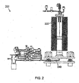
- FIG. 2 shows a fluidized bed reactor that may be used in accordance with one embodiment of the present disclosure.
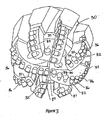
- FIG. 3 is a perspective side view of a drag bit in accordance with one embodiment of the present disclosure.
- FIG. 4 is a perspective side view of an impreg bit in accordance with one embodiment of the present disclosure.
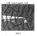
- FIG. 5 is a schematic according to one embodiment of the present disclosure.
- embodiments disclosed herein relate to composite or matrix bodies used in components of downhole cutting tools, including drill bits, mining picks, core bits, etc.
- embodiments relate to composite bodies having formed from tungsten carbide particles surrounded by a ductile metal matrix binder with a reinforcing nanotubular material.
- embodiments of the present disclosure provide composite bodies which are formed from such tungsten carbides infiltrated by suitable metals or alloys as infiltration binders. Such a composite body may have high transverse rupture strength and toughness while maintaining wear and erosion resistance. Embodiments of the present disclosure are based, in part, on the determination that the life of a composite bit body is related to the body's strength (also known as transverse rupture strength), toughness, and resistance to erosion.
- FIG. 1 illustrates the conventional microstructure of cemented tungsten carbide.
- cemented tungsten carbide 10 includes tungsten carbide grains 12 that are bonded to one another by a metal binder phase 14.
- tungsten carbide grains may be bonded to other grains of tungsten carbide, thereby having a tungsten carbide/tungsten carbide interface, and/or may be bonded to the metal phase, thereby having a tungsten carbide/metal interface.
- the unique properties of cemented tungsten carbide result from this combination of a rigid carbide network with a tougher metal substructure.
- the generic microstructure of cemented tungsten carbide, a heterogenous composite of a ceramic phase in combination with a metal phase, is similar in all cermets.
- the relatively low fracture toughness of cemented tungsten carbide has proved to be a limiting factor in more demanding applications, such as in roller cone rock bits, hammer bits and drag bits used for subterranean drilling and the like. It is possible to increase the toughness of the cemented tungsten carbide by increasing the amount of metal binder present in the composite.
- the toughness of the composite mainly comes from plastic deformation of the metal phase during the fracture process. Yet, the resulting hardness of the composite decreases as the amount of ductile metal increases. Thus, an upper limit on the amount of metal phase typically exists.
- the metal phase is not necessarily continuous in the conventional cemented tungsten carbide microstructure, particularly in compositions having a low metal concentration.
- a relatively uniform distribution of tungsten carbide in a metal matrix is desired, typically inadequate mixing/infiltration results in agglomerates of tungsten carbide particles and pools of binder.
- a crack propagating through the composite will often travel through the less ductile tungsten carbide grains, either transgranularly through tungsten carbide/metal interfaces or intergranularly through tungsten carbide/tungsten carbide interfaces.
- cemented tungsten carbide often exhibits gross brittle fracture during more demanding applications, which may lead to catastrophic failure.
- embodiments of the present disclosure may include composite body constructions comprising hard phase particulate materials and a relatively softer binder phase material, where the composite body construction is also provided with a reinforcing nanotube material.
- a cermet or sintered material formed with a reinforcing nanotube material may find particular use as cutting tool composite bodies.
- nanotube material refers to various materials having having a cylindrical or tubular configuration with at least one dimension, such as length or diameter, between 1 and 100 nanometers.
- Types of nanotubes that may find use as a reinforcing nanotubes material in the present disclosure may include carbon nanotubes (CNTs), including both single-walled (SWNT), double-walled (DWNT), multi-walled (MWNT), inorganic nanotubes, multibranched nanotubes, and CNT-C 60 hybrids. Additionally, in some embodiments, at least a portion of the surface of the reinforcing nanotubes may be modified.
- Carbon nanotubes are polymers of pure carbon, which may be functionalized or otherwise modified. Both SWNTs and MWNTs are known in the art and the subject of a considerable body of published literature. Examples of literature on the subject are Dresselhaus, M. S., et al., Science of Fullerenes and Carbon Nanotubes, Academic Press, San Diego (1996 ), and Ajayan, P. M., et al., "Nanometre-Size Tubes of Carbon,” Rep. Prog. Phys. 60 (1997): 1025-1062 .
- the structure of a single-wall carbon nanotube may be described as a single graphene sheet rolled into a seamless cylinder whose ends are either open or closed. When closed, the ends are capped by either half fullerenes or more complex structures including pentagons.
- Nanotubes frequently exist as “ropes," or bundles of 10 to 100 nanotubes held together along their length by van der Waals forces, with individual nanotubes branching off and joining nanotubes of other "ropes.”
- Multi-walled carbon nanotubes are multiple concentric cylinders of graphene sheets. The cylinders are of successively larger diameter to fit one inside another, forming a layered composite tube bonded together by van der Waals forces, with a typical distance of approximately 0.34 nm between layers, as reported by Peigney, A., et al., “Carbon nanotubes in novel ceramic matrix nanocomposites,” Ceram. Inter. 26 (2000) 677-683 .
- Carbon nanotubes are commonly prepared by arc discharge between carbon electrodes in an inert gas atmosphere.
- the product is generally a mixture of single-wall and multi-wall nanotubes, although the formation of single-wall nanotubes can be favored by the use of transition metal catalysts such as iron or cobalt.
- transition metal catalysts such as iron or cobalt.
- the electric arc method, as well as other methods for the synthesis of carbon nanotubes is described in, for example, " Nanometre-Size Tubes of Carbon," P.M. Ajayan and T.W. Ebbesen, Rep. Prog. Phys., 60, 1025-1062 (1997) .
- Inorganic nanotubes may include those prepared from a range of materials including boron nitride, silicon nitride, silicon carbide, dichalcogenides, for example, WS 2 , oxides such as HfO 2 and MoO 3 , metallic nanotubes, such as Co and Au, and materials having a composition B x C y N z , where x, y, and z may be independently selected from 0 to 4, including for example, BC 2 N 2 and BC 4 N, and combinations thereof.
- the average diameter of the nanotube materials may range from about 1 to 100 nanometers.
- the reinforcing phase may include SWNTs having an average diameter of about 1 to 2 nanometers and/or MWNTs having an average diameter of about 2 to 30 nanometers.
- Nanotube materials typically have a very high aspect ratio, that is, the ratio of length to diameter.
- the nanotubes used in the present disclosure may have an aspect ratio ranging from about 25 to 1,000,000, and preferably from about 100 to about 1,000.
- the surface of the carbon nanotubes may, in one embodiment, be modified prior to incorporation into the composites of the present disclosure.
- the nanostructured carbon material is modified by a chemical means to yield derivatized nanostructured carbon material.
- derivatization refers to the attachment of other chemical entities to the nanostructured carbon material, which may be by chemical or physical means including, but not limited to, covalent bonding, van der Waals forces, electrostatic forces, physical entanglement, and combinations thereof.
- the nanostructured carbon material is modified by a physical means selected from the group consisting of plasma treatment, heat treatment, ion bombardment, attrition by impact, milling and combinations thereof.
- the nanostructured carbon material is modified by a chemical means selected from the group consisting of chemical etching by acids either in liquid or gaseous form, chemical etching by bases either in liquid or gaseous form, electrochemical treatments, and combinations thereof.
- derivatization or functionalization may be desired so as to increase ease in solubilization and/or disperson of the nanotubes into at least one of the component phases prior to formation of a composite material.
- Functionalization or derivatization may occur by the incorporation of various chemical moieties on either end caps and/or sidewalls (either exterior or interior) of the nanotube materials, or with a coating placed thereon.
- functionalization may occur through covalent and/or non-covalent functionalization, endcap and/or sidewall functionalization, exohedral and/or endohedral functionalization and supramolecular complexation.
- a variety of functionalized nanotubes have been developed so as to enable dispersion of the nanostructures into composite materials, including fluoronanotubes, carboxy-nanotubes, and various covalently bonded nanotubes, including amino-CNTs, vinyl-CNTs, epoxy-CNTs. Oxidation of nanotubes may result in carboxyl, hydroxyl, or carbonyl groups, which may be further modified via amidation or etherification, for example.
- the nanotube materials of the present disclosure may be provided with ultra-thin, conformal coating thereon.
- ultra-thin refers to a thickness of less than 100 nm.
- the ultra-thin coating may have a thickness ranging from about 0.1 to about 50 nm, from about 0.5 to 35 nm in another embodiment, and from about 1 to 10 nm in yet another embodiment.
- Conformal refers to a relatively uniform thickness across the surface of the particle such that the surface shape of a coated particle is substantially similar to that of the uncoated particle.
- the composition of the coatings may vary.
- the coating may include a sinterable material including, for example, metals, metal alloys, ceramic materials, and cermets.
- coatings that may be suitable for use on the nanotube materials of the present disclosure may include metals and binary materials, i.e., materials of the form Q x Ry, where Q and R represent different atoms and x and y are numbers that reflect an electrostatically neutral material.
- binary materials include various inorganic ceramic materials including oxides, nitrides, carbides, sulfides, fluorides, and combinations thereof.
- oxides that may find use in the present disclosure include those such as CoO, Al 2 O 3 , TiO 2 , Ta 2 O 5 , Nb 2 O 5 , ZrO 2 , HfO 2 , SnO 2 , ZnO, La 2 O 3 , Y 2 O 3 , CeO 2 Sc 2 O 3 , Er 2 O 3 , V 2 O 5 , SiO 2 , In 2 O 3 , and the like.
- nitrides that may find use in the present disclosure include those such as Si 3 N 4 , A1N, TaN, NbN, TiN, MoN, ZrN, HfN, GaN, and the like.
- Examples of carbides that may find use in the present disclosure include those such as SiC, WC, and the like.
- Examples of sulfides that may find use in the present disclosure include those such as ZnS, SrS, CaS, PbS, and the like.
- Examples of fluorides that may find use in the present disclosure include those such as CaF 2 , SrF 2 , ZnF 2 , and the like.
- suitable metal coatings include Pt, Ru, Ir, Pd, Cu, Fe, Co, Ni, W, and the like.
- Other types of materials that may be used to form an ultra-thin conformal coating include those described in U.S. Patent No. 6,613,383 , which is hereby incorporated by reference in its entirety.
- Coatings suitable for use in the present disclosure may also include mixed structures, such as TiA1N, Ti3A1N, ATO (AlTiO), coatings including doped metals, such as ZnO:Al, ZnS:Mn, SrS:Ce, Al 2 O 3 :Er, ZrO 2 :Y, which may also include other rare earth metals (Ce 3+ , Tb 3+ , etc.) for doping or co-doping, or nanolaminates, such as HfO 2 /Ta 2 O 5 , TiO 2 /Ta 2 O 5 , TiO 2 /Al 2 O 3 , ZnS/Al 2 O 3 , and the like.
- doped metals such as ZnO:Al, ZnS:Mn, SrS:Ce, Al 2 O 3 :Er, ZrO 2 :Y, which may also include other rare earth metals (Ce 3+ , Tb 3+ , etc.) for doping or
- inorganic species such as inorganic polymers may be suitable for coatings of the present disclosure, including inorganic polymers such as, for example, polysilanes, polysiloxanes, polystannanes, polyphosphazene, polysulfides, and hybrid polymers of a grafted inorganic and organic polymer.
- inorganic polymers such as, for example, polysilanes, polysiloxanes, polystannanes, polyphosphazene, polysulfides, and hybrid polymers of a grafted inorganic and organic polymer.
- the coating itself may be a reagent or catalyst that functions as a sintering aid in the formation of a cermet composite.
- the ultra-thin coating may provide a high surface area of catalyst or reactive material and/or provide a means for finely dispersing the coating material.
- the tubular materials of the present disclosure may be coated with a material such as aluminum oxide, which may function as a sintering aid.
- the ultra-thin, conformal coating of the present disclosure may be applied on the tubular materials through atomic layer controlled growth techniques or atomic layer deposition (ALD).
- ALD deposition of coatings is described, for example, in U.S. Patent No. 6,913,827 , which is herein incorporated by reference in its entirety.
- ALD methods use self-limiting surface chemistry to control deposition. Under the appropriate conditions, deposition may be limited to a small number of functional groups on the surface, i.e., approximately one monolayer or ⁇ 1 x 10 15 species per cm 2 .
- ALD permits the deposition of coatings of up to about 0.3 nm in thickness per reaction cycle, and thus provide a means for controlling thickness to extremely fine thicknesses.
- the coating may be formed in a series of two or more self-limited reactions, which in most instances can be repeated to subsequently deposit additional layers of the coating material until a desired coating thickness is achieved.
- the first of these reactions may involve some functional group on the surface of the particle, such as an M-H, M-O-H, or M-N-H group, where M represents an atom of a metal or semi-metal.
- the individual reactions may be carried out separately and under conditions such that all excess reagents and reaction products are removed before concluding the succeeding reaction.
- the particles may optionally be treated prior to initiating the reaction sequence to remove volatile materials that may have absorbed onto the surface of the particulate materials. This may be readily done by exposing the particles to elevated temperatures and/or vacuum.
- a precursor reaction may be performed to introduce desirable functional groups onto the surface of the tubular material to facilitate a reaction sequence in creating an ultra-thin coating.
- functional groups include hydroxyl groups, amino groups, and metal-hydrogen bonds, which may serve as a site of further reaction to allow formation of an ultra-thin coating.
- Functionalization may be achieved through surface treatments including, for example, water plasma treatment, ozone treatment, ammonia treatment, and hydrogen treatment.
- Oxide coatings may be prepared on particles having surface hydroxyl or amine (M-N-H) groups using a binary (AB) reaction sequence as follows.
- the asterisk (*) indicates the atom that resides at the surface of the particle or coating, and Z represents oxygen or nitrogen.
- M 1 is an atom of a metal (or semimetal such as silicon), particularly one having a valence of 3 or 4, and X is a displaceable nucleophilic group.
- the reactions shown below are not balanced, and are only intended to show the reactions at the surface of the particles (i.e., not inter- or intralayer reactions).
- reaction A1 reagent M 1 X n reacts with one or more M-Z-H groups on the surface of the particle to create a "new" surface group having the form -M 1 X.
- M 1 is bonded to the particle through one or more Z atoms.
- the -M 1 X group represents a site that can react with water in reaction B1 to regenerate one or more hydroxyl groups.
- reaction B1 can serve as functional groups through which reactions A1 and B1 can be repeated, each time adding a new layer of M 1 atoms.
- Atomic layer controlled growth and additional binary reactions are described in more detail in U.S. Patent No. 6,613,383 , which is herein incorporated by reference in its entirety.
- a convenient method for applying the ultra-thin, conformal coating to particulate material is to form a fluidized bed of the particles, and then pass the various reagents in turn through the fluidized bed under reaction conditions.
- Methods of fluidizing particulate material are well known and are described, for example, " Nanocoating Individual Cohesitve Boron Nitride Particles in a Fluidized Bed Reactor," Jeffrey R. Wank, et al., Powder Technology 142 (2004) 59-69 . Briefly, the ALD process using a fluidized bed reactor, illustrated in FIG. 2, is described. Uncoated particles may be supported on a porous plate or screen 220 within a fluidized bed reactor 200.
- a fluidizing gas (such as N 2 ) may be passed into the reactor 200 through line 240 and upwardly through the plate or screen 220, lifting the particles and creating a fluidized bed.
- Fluid (gaseous or liquid) reagents may be introduced into the bed 200 also through line 240 for reaction with the surface of the particles.
- the fluidizing gas may also act as an inert purge gas following each dosing of the particles with reagent for removing unreacted reagents and volatile or gaseous reaction products.
- ultra-thin coatings may be deposited on the particulate material.
- an intermediate ultra-thin layer may be applied to provide a surface to which a desired outer layer can be applied more easily.
- the multiple layers may possess identical compositions, or the multiple layers may vary in composition. It is specifically within the scope of the present disclosure that the multiple layers may include combinations of any of the above described coating compositions such, for example, metal-on-metal, metal-on-oxide, and oxide-on-oxide.
- the coating may undergo a number of transitions.
- an ALD bilayer of Al 2 O 3 /TiO 2 after sintering, may react and form an aluminum titanate coating.
- a subsequent coating layer may be deposited by a method other than ALD, such as CVD or PVD, for example, on an ALD-deposited coating.
- a coating may be applied using atomic layer deposition methods as described above, and the coating may subjected to one or more reactions to form a modified coating.
- This technique may be used, for example, for creating ultra-thin coatings of various types that are not amenable to deposition using atomic layer deposition techniques.
- various types of ultra-thin oxide coatings can be formed using the atomic layer deposition techniques described above, and then can be carburized to convert the oxide to the corresponding carbide.
- the coatings disclosed herein may, in various embodiments, be either amorphous or crystalline in nature. Further, if a coating is amorphous in nature and is desirably crystalline, the particle having the coating thereon may be placed in a furnace at the appropriate environment for crystallization of the coating. In a particular embodiment, crystallization may occur in air at temperature of at least 600°C.
- various inorganic nanotubes may include those formed using a carbon nanotube as a template, applying a conformal coating via ALD on the carbon nanotubes, and then removing the carbon nanotube, such as by etching, to form an inorganic nanotube.
- Such inorganic coatings, and thus nanotubes may include the various coatings described above.
- U.S. Patent No. 7,005,391 which is herein incorporated by reference in its entirety, discloses the formation of such inorganic nanotubes via ALD and subsequent etching of the underlying carbon nanotube template.
- a hard phase particulate materials that may be used with reinforcing tubular materials to form the composite materials of the present disclosure may include various materials used to form cermet materials having application in the drill bit and cutting tool industry.
- the hard phase materials may include tungsten carbide particles or other metal carbides, such as titanium and tantalum carbides, and the like.
- tungsten carbide particles that may be used to form composite bodies of the present disclosure include cast tungsten carbide, macro-crystalline tungsten carbide, carburized tungsten carbide, and cemented tungsten carbide.
- Suitable particle sizes for the hard phase particulate material of the present disclosure may range up to 500 microns in one embodiment, and from the nanometer range (e.g., about 0.001 microns) to about 100 microns in another embodiment, and from about 0.005 to 50 microns in yet another embodiment.
- the particulate materials of the present disclosure have surface areas ranging from about 0.1 to 200 m 2 /g or more.
- tungsten carbide is macrocrystalline carbide. This material is essentially stoichiometric WC in the form of single crystals. Most of the macrocrystalline tungsten carbide is in the form of single crystals, but some bicrystals of WC may form in larger particles.
- the manufacture of macrocrystalline tungsten carbide is disclosed, for example, in U.S. Patent Nos. 3,379,503 and 4,834,963 , which are herein incorporated by reference.
- Carburized tungsten carbide as known in the art, is a product of the solid-state diffusion of carbon into tungsten metal at high temperatures in a protective atmosphere.
- Carburized tungsten carbide grains are typically multi-crystalline, i.e., they are composed of WC agglomerates. The agglomerates form grains that are larger than individual WC crystals. These larger grains make it possible for a metal infiltrant or an infiltration binder to infiltrate a powder of such large grains.
- Typical carburized tungsten carbide contains a minimum of 99.8% by weight of carbon infiltrated WC, with a total carbon content in the range of about 6.08% to about 6.18% by weight.
- Tungsten carbide grains designated as WC MAS 2000 and 3000-5000, commercially available from H.C. Stark, are carburized tungsten carbides suitable for use in the formation of the matrix bit body disclosed herein.
- the MAS 2000 and 3000-5000 carbides have an average size of 20 and 30-50 micrometers, respectively, and are coarse grain conglomerates formed as a result of the extreme high temperatures used during the carburization process.
- cemented tungsten carbide also known as sintered tungsten carbide
- sintered tungsten carbide is a material formed by mixing particles of tungsten carbide, typically monotungsten carbide, and cobalt particles, and sintering the mixture.
- Methods of manufacturing cemented tungsten carbide are disclosed, for example, in U.S. Patent Nos. 5,541,006 and 6,908,688 , which are herein incorporated by reference.
- Sintered tungsten carbide is commercially available in two basic forms: crushed and spherical (or pelletized). Crushed sintered tungsten carbide is produced by crushing sintered components into finer particles, resulting in more irregular and angular shapes, whereas pelletized sintered tungsten carbide is generally rounded or spherical in shape.
- a tungsten carbide powder having a predetermined size is mixed with a suitable quantity of cobalt, nickel, or other suitable binder.
- the mixture is typically prepared for sintering by either of two techniques: it may be pressed into solid bodies often referred to as green compacts, or alternatively, the mixture may be formed into granules or pellets such as by pressing through a screen, or tumbling and then screened to obtain more or less uniform pellet size.
- Such green compacts or pellets are then heated in a controlled atmosphere furnace to a temperature near the melting point of cobalt (or the like) to cause the tungsten carbide particles to be bonded together by the metallic phase.
- Crushed cemented tungsten carbide may further be formed from the compact bodies or by crushing sintered pellets or by forming irregular shaped solid bodies.
- the particle size and quality of the sintered tungsten carbide can be tailored by varying the initial particle size of tungsten carbide and cobalt, controlling the pellet size, adjusting the sintering time and temperature, and/or repeated crushing larger cemented carbides into smaller pieces until a desired size is obtained.
- tungsten carbide particles (unsintered) having an average particle size of between about 0.2 to about 20 microns are sintered with cobalt to form either spherical or crushed cemented tungsten carbide.
- the cemented tungsten carbide is formed from tungsten carbide particles having an average particle size of about 0.8 to about 5 microns.
- the amount of cobalt present in the cemented tungsten carbide is such that the cemented carbide is comprised of from about 6 to 8 weight percent cobalt.
- Cast tungsten carbide is another form of tungsten carbide and has approximately the eutectic composition between bitungsten carbide, W 2 C, and monotungsten carbide, WC.
- Cast carbide is typically made by resistance heating tungsten in contact with carbon, and is available in two forms: crushed cast tungsten carbide and spherical cast tungsten carbide. Processes for producing spherical cast carbide particles are described in U.S. Pat. Nos. 4,723,996 and 5,089,182 , which are herein incorporated by reference. Briefly, tungsten may be heated in a graphite crucible having a hole through which a resultant eutectic mixture of W 2 C and WC may drip.
- This liquid may be quenched in a bath of oil and may be subsequently comminuted or crushed to a desired particle size to form what is referred to as crushed cast tungsten carbide.
- a mixture of tungsten and carbon is heated above its melting point into a constantly flowing stream which is poured onto a rotating cooling surface, typically a water-cooled casting cone, pipe, or concave turntable.
- the molten stream is rapidly cooled on the rotating surface and forms spherical particles of eutectic tungsten carbide, which are referred to as spherical cast tungsten carbide.
- the standard eutectic mixture of WC and W 2 C is typically about 4.5 weight percent carbon.
- Cast tungsten carbide commercially used as a matrix powder typically has a hypoeutectic carbon content of about 4 weight percent.
- the cast tungsten carbide used in the mixture of tungsten carbides is comprised of from about 3.7 to about 4.2 weight percent carbon.
- the various tungsten carbides disclosed herein may be selected so as to provide a bit that is tailored for a particular drilling, mining, or other cutting application.
- the type, shape, and/or size of carbide particles used in the formation of a composite bit body may affect the material properties of the formed composite body, including, for example, fracture toughness, transverse rupture strength, and erosion resistance.
- the mixture includes preferably at least 80% by weight carbide of the total matrix powder. While reference is made to tungsten carbide, other carbides of Group 4a, 5a, or 6a metals may be used. Although the total carbide may be used in an amount less than 80% by weight of the matrix powder, such matrix bodies may not possess the desired physical properties to yield optimal performance.
- the carbide particles may be surrounded by a metallic binder.
- the metallic binder may be formed from a metallic binder powder and/or an infiltration binder.
- the metallic binder powder may be pre-blended with the matrix powder hard carbide particles.
- matrix powder is infiltrated by an infiltration binder.
- infiltration binder herein refers to a metal or an alloy used in an infiltration process to bond the various particles of tungsten carbide forms together.
- Catalyst materials that may be used to form the relative ductile phase of the various composites of the present disclosure may include all transition metals, main group metals and alloys thereof, including various group IVa, Va, and VIa ductile metals and metal alloys including, but not limited to Fe, Ni, Co, Cu, Ti, Al, Ta, Mo, Nb, W, V, and alloys thereof, including alloys with materials selected from C, B, Cr, and Mn.
- copper, nickel, iron, and cobalt may be used as the major constituents in the infiltration binder.
- Other elements, such as aluminum, manganese, chromium, zinc, tin, silicon, silver, boron, and lead, may also be present in the infiltration binder.
- the infiltration binder is selected from at least one of nickel, copper, and alloys thereof.
- the infiltration binder includes a Cu-Mn-Ni-Zn alloy.
- the particulate material comprises tungsten carbide particles and a metallic binder powder.
- nickel and/or iron powder may be present as the balance of the matrix powder, typically from about 2% to 12% by weight.
- other Group VIIIB metals such as cobalt and various alloys may also be used.
- Co and/or Ni is present as the balance of the mixture in a range of about 2% to 15% by weight.
- Metal addition in the range of about 1% to about 12% may yield higher matrix strength and toughness, as well as higher braze strength.
- the matrix powder comprises nickel in an amount ranging from about 2 to 4 weight percent of the matrix powder and iron in an amount ranging from about 0.5 to 1.5 weight percent of the matrix powder.
- the ductile binder phase may include a compound containing silicon and/or titanium and oxygen, and a titanate, silicate, or complex oxide of a metal selected from the group of iron, cobalt, nickel and manganese in another embodiment.
- titanates and silicates as binders is described, for example, in U.S. Patent No. 5,769,176 , which is herein incorporated by reference in its entirety.
- the ductile binder phase may include any of the compositions that may comprise the ultra-thin coating discussed above.
- the composites of the present disclosure may be prepared by forming a mixture or blend of a hard particulate/ceramic powder phase and a metal phase with a nanotube filler integrated into at least one of the two phases.
- the amount of nanotube filler that may be used in the matrix bodies of the present disclosure may range from about 0.5 to 50 parts by volume (of the mixture) in one embodiment, and from 1 to 20 parts by volume in another embodiment.
- the nanotube material may be present in an amount up to 10 percent by volume and up to 1 percent by volume in yet another embodiment.
- the nanotubes may be present in an amount up to one-third of the metallic binder present in the composite body.
- Integration of the nanotube filler into the matrix body may include any means as known to those skilled in the art.
- integration refers to any means for adding the nanotubes to a component of the composite body such that the nanotubes are a component of the formed composite body, i.e., by dispersion or other forms of incorporation of the nanotube filler as known to those skilled in the art.
- the nanotubes may be integrated in such a manner so as to achieve a generally uniform dispersion of the nanotubes through the formed composite body.
- blending of the nanotube fillers with a carbide particulate phase may be accomplished by any suitable wet mixing technique that will provide a dispersion of the nanotube filler in the carbide powder.
- a homogenous dispersion, with minimal agglomeration and clumping may be prepared, for example, by dispersing the components, individually or as a mixture, in a mixing medium, such as a low molecular weight alcohol (e.g., ethanol), with an ultrasonic probe, blending the dispersions of the components that are individually dispersed, and evaporating the solvent in an ultrasonic bath.
- a mixing medium such as a low molecular weight alcohol (e.g., ethanol)
- the mixing media may optionally contain a surfactant, as known to those of skill in the art, that may further promote dispersion of the nanotubes in the particulate phase.
- a surfactant as known to those of skill in the art, that may further promote dispersion of the nanotubes in the particulate phase.
- the nanotubles may alternatively be mixed with a binder phase.
- dry mixing or mixing with other volatile media may also be used.
- Mechanical mixing may be performed by ball-milling in conventional rotary mills that mix the powder mixture with the assistance of tumbling balls.
- the sizes of the balls, the number of balls used per unit volume of powder, the rotation speed of the mill, the temperature at which the milling is performed, and the length of time that milling is continued can all vary widely. Best results may generally be achieved with a milling time ranging from about 4 hours to about 50 hours.
- the degree of mixing may also be affected by the "charge ratio," which is the ratio of the mass of the balls to the mass of the powder. A charge ratio of from about 5 to about 20 will generally provide proper mixing.
- the milling may be performed on the powders while suspended in the liquid suspending agent referred to above.
- nanotubes into the composites of the present disclosure, such as, for example, vapor co-deposition (in which the nanostructure material and a particulate phase are sublimed, mixed in the vapor phase, and then condensed on a substrate), spraying coating of particles or the infiltration binder (such as that described in U.S. Patent Publication No. 20030012951 , which is herein incorporated by reference in its entirety), infiltration by electromagnetic levitation (such as that described in U.S. Patent Publication No. 2004/0206470 , which is herein incorporation by reference in its entirety), extrusion, either high or regular shear, (such as that described in U.S. Patent Publication No. 20040029706 , which is herein incorporated by reference in its entirety), or infiltration of a perform (such as that described in U.S. Patent No. 6,934,600 ).
- vapor co-deposition in which the nanostructure material and a particulate phase are sublimed, mixed in the vapor phase, and then condensed on
- the nanotubes may be incorporated in the composite body in such a manner as to form a random distribution. In other embodiments, however, the nanotubes may be incorporated in such as manner so that the nanotubes may have an oriented structure, such as uniform orientation in two dimensions or three dimensions.
- U.S. Patent Nos. 7,105,596 and 6,790,425 which are herein incorporated by reference in their entirety, discuss the macroscopic assembly of nanotubes in a structure.
- the composite bodies of the present disclosure may be prepared by a number of different methods, e.g., by infiltration, casting, or other sintering techniques, including layered manufacturing. Further, one of ordinary skill in the art would appreciate that other methods may be used, such as, for example, solid state or liquid phase sintering, pneumatic isostatic forging, spark plasma sintering, microwave sintering, gas phase sintering, and hot isostatic pressing.
- Infiltration processes that may be used to form a composite body of the present disclosure may begin with the fabrication of a mold, having the desired body shape and component configuration.
- a mass of carbide particles and, optionally, metal binder powder may be infiltrated with a molten infiltration binder.
- the nanotube materials may be integrated into the resulting composite body through at least one of the carbide particles, the metal binder powder, and the infiltration binder.
- casting processes may be used, in which a molten mixture of carbide particles, a binder, and nanotube particles may be either poured into a mold, or melted within a mold, and then cooled to cast the composite body.
- the nanotube materials may be integrated into the resulting composite body through at least one of the carbide particles or metal binder.
- Layered manufacturing of a composite body involves the sintering of a first layer of particles together by a layered manufacturing equipment, after which a second layer of particles is disposed over the first layer and sintered in selected regions of the second layer together and to the first layer. The process repeats to fabricate subsequent layers until the desired part has been formed from the composite material particles.
- the particulate-based part may be infiltrated with a binder material that binds adjacent particles of matrix material together, and forms a substantially integral part that represents the model used to generate the bit body or other article.
- U.S. Patent Nos. 5,544,550 and 5,433,280 discuss the use of layered manufacturing techniques to form bit bodies.
- the nanotube materials may be integrated into the resulting composite body through at least one of the carbide particles or metal binder.
- Composite bodies of the present disclosure may be used in a number of different applications, such as tools for drilling, mining, and construction applications, including for example, composite bodies for drill bits, mining picks, core bits, etc, where mechanical properties of high fracture toughness, wear resistance, and hardness are highly desired. Additionally, the composite body may be used to form bit bodies and/or other wear and cutting components in such downhole cutting tools as roller cone bits, percussion or hammer bits, and drag bits, and a number of different cutting and machine tools.
- a drag bit body 30 is formed with blades 32 at its lower end.
- a plurality of recesses or pockets 34 are formed in the faces to receive a plurality of conventional polycrystalline diamond compact cutters 36.
- the PDC cutters typically cylindrical in shape, are made from a hard material such as tungsten carbide and have a polycrystalline diamond layer covering the cutting face 37.
- the PDC cutters are brazed into the pockets after the bit body 30 has been made.
- the bit body 30 comprises a composite body formed in accordance with the present disclosure. Methods of making composite or matrix bit bodies are known in the art and are disclosed for example in U.S. Patent No. 6,287,360 , which is assigned to the assignee of the present invention and hereby incorporated by reference in its entirety.
- a diamond impregnated drill bit 40 includes a shank 44 and a crown 46.
- Shank 44 may be formed of steel and includes a threaded pin 48 for attachment to a drill string.
- Crown 46 has a cutting face 42 and outer side surface 45.
- crown 46 is a composite bit body according to one embodiment of the present invention. Additionally, crown 46 may optionally include various surface features, such as raised ridges 47 and inserts 49.
- inserts 49 may be mounted in the sockets (not shown) and affixed by any suitable method, such as brazing, adhesive, mechanical means such as interference fit, or the like.
- matrix bodies of the present disclosure having reinforcing nanotube materials therein may provide for an increase in toughness.
- FIG. 5 a schematic of the reinforcing effects of the nanotube material in a matrix body of the present disclosure is shown.
- the nanotube materials may reinforce the composite material in one or more of several mechanisms.
- incorporation of nanotubes may allow for fiber bridging 52, i.e., the bridging of the crack wake by the nanotubes.
- a toughening effect may also be achieved when the nanotubes either distributing load from the crack tip while remaining intact, debonding between the nanotubes and the surrounding material followed by pull-out 84, and/or fracture of the individual nanotubes 56 followed by energy adsorption through pull-out of the broken nanotube.
- An alternative theory of a toughening mechanism is crack deflection 58. When a crack propagates through a material, a nanotube being of greater strength than the surrounding material, depending on the orientation of the nanotube in the composite, crack propagation may be deflected away from the axis of highest stress to a less efficient plane directed by the longitudinal orientation of the nanotube. This may lead to increased fracture energy through increased fracture surface area and lower driving forces due to the reduced resolved normal stresses at the crack tip.
- embodiments of the present disclosure may provide for at least one of the following.
- a reinforcing nanotube material into a composite body, composite bodies may be formed having an increased toughness.
- the increases in toughness may be obtained by adding nanotubes, the fracture toughness may be increased without substantially altering the composition, and thus wear resistance of the body.
- Incorporation of coated nanotubes into the composite material may provide for increased wettability and interfacial adhesion of the nanotubes within the surrounding metal phase, thereby resulting in a homogenous dispersion in the composite. Improvements in creep resistance and stress relaxation in coated nanotubes may further allow for improved high temperature performance of reinforced composite structures.
Landscapes
- Chemical & Material Sciences (AREA)
- Engineering & Computer Science (AREA)
- Materials Engineering (AREA)
- Nanotechnology (AREA)
- Organic Chemistry (AREA)
- Mechanical Engineering (AREA)
- Metallurgy (AREA)
- Physics & Mathematics (AREA)
- Inorganic Chemistry (AREA)
- Composite Materials (AREA)
- Condensed Matter Physics & Semiconductors (AREA)
- General Physics & Mathematics (AREA)
- Crystallography & Structural Chemistry (AREA)
- Chemical Kinetics & Catalysis (AREA)
- Powder Metallurgy (AREA)
- Earth Drilling (AREA)
- Drilling Tools (AREA)
Applications Claiming Priority (3)
| Application Number | Priority Date | Filing Date | Title |
|---|---|---|---|
| US85883006P | 2006-11-14 | 2006-11-14 | |
| US91716307P | 2007-05-10 | 2007-05-10 | |
| US11/939,330 US20080210473A1 (en) | 2006-11-14 | 2007-11-13 | Hybrid carbon nanotube reinforced composite bodies |
Publications (2)
| Publication Number | Publication Date |
|---|---|
| EP1923154A2 true EP1923154A2 (de) | 2008-05-21 |
| EP1923154A3 EP1923154A3 (de) | 2009-08-12 |
Family
ID=39247775
Family Applications (1)
| Application Number | Title | Priority Date | Filing Date |
|---|---|---|---|
| EP07120685A Withdrawn EP1923154A3 (de) | 2006-11-14 | 2007-11-14 | Mit Hybridkohlenstoff-Nanoröhrchen verstärkte Kompositkörper |
Country Status (2)
| Country | Link |
|---|---|
| US (1) | US20080210473A1 (de) |
| EP (1) | EP1923154A3 (de) |
Cited By (6)
| Publication number | Priority date | Publication date | Assignee | Title |
|---|---|---|---|---|
| WO2009036112A1 (en) * | 2007-09-12 | 2009-03-19 | Baker Hughes Incorporated | Hardfacing containing fullerenes for subterranean tools and methods of making |
| RU2471012C1 (ru) * | 2011-12-20 | 2012-12-27 | Виктор Николаевич Мироненко | Порошковый композиционный материал |
| EP2391470A4 (de) * | 2009-01-29 | 2014-04-30 | Baker Hughes Inc | Rotierender partikelmatrix-erdbohrmeissel und herstellungsverfahren dafür |
| CN104975201A (zh) * | 2014-04-14 | 2015-10-14 | 现代自动车株式会社 | 纳米碳增强的铝复合材料及其制造方法 |
| CN107999866A (zh) * | 2017-11-30 | 2018-05-08 | 株洲三鑫硬质合金生产有限公司 | 一种硬质合金圆盘切脚刀及其生产工艺 |
| CN112974797A (zh) * | 2021-02-07 | 2021-06-18 | 哈尔滨工业大学 | 一种利用微波在金刚石表面制备高结合强度碳化物涂层的方法 |
Families Citing this family (55)
| Publication number | Priority date | Publication date | Assignee | Title |
|---|---|---|---|---|
| US9682425B2 (en) | 2009-12-08 | 2017-06-20 | Baker Hughes Incorporated | Coated metallic powder and method of making the same |
| US8403037B2 (en) | 2009-12-08 | 2013-03-26 | Baker Hughes Incorporated | Dissolvable tool and method |
| US9079246B2 (en) | 2009-12-08 | 2015-07-14 | Baker Hughes Incorporated | Method of making a nanomatrix powder metal compact |
| US9101978B2 (en) | 2002-12-08 | 2015-08-11 | Baker Hughes Incorporated | Nanomatrix powder metal compact |
| US9109429B2 (en) | 2002-12-08 | 2015-08-18 | Baker Hughes Incorporated | Engineered powder compact composite material |
| US20080179104A1 (en) * | 2006-11-14 | 2008-07-31 | Smith International, Inc. | Nano-reinforced wc-co for improved properties |
| WO2010036569A2 (en) * | 2008-09-24 | 2010-04-01 | Smith International, Inc. | Novel hardmetal for use in oil and gas drilling applications |
| US20100155148A1 (en) * | 2008-12-22 | 2010-06-24 | Baker Hughes Incorporated | Earth-Boring Particle-Matrix Rotary Drill Bit and Method of Making the Same |
| US8727042B2 (en) | 2009-09-11 | 2014-05-20 | Baker Hughes Incorporated | Polycrystalline compacts having material disposed in interstitial spaces therein, and cutting elements including such compacts |
| US8800693B2 (en) | 2010-11-08 | 2014-08-12 | Baker Hughes Incorporated | Polycrystalline compacts including nanoparticulate inclusions, cutting elements and earth-boring tools including such compacts, and methods of forming same |
| US8579052B2 (en) * | 2009-08-07 | 2013-11-12 | Baker Hughes Incorporated | Polycrystalline compacts including in-situ nucleated grains, earth-boring tools including such compacts, and methods of forming such compacts and tools |
| US8496076B2 (en) * | 2009-10-15 | 2013-07-30 | Baker Hughes Incorporated | Polycrystalline compacts including nanoparticulate inclusions, cutting elements and earth-boring tools including such compacts, and methods of forming such compacts |
| US9243475B2 (en) | 2009-12-08 | 2016-01-26 | Baker Hughes Incorporated | Extruded powder metal compact |
| US8528633B2 (en) | 2009-12-08 | 2013-09-10 | Baker Hughes Incorporated | Dissolvable tool and method |
| US9127515B2 (en) | 2010-10-27 | 2015-09-08 | Baker Hughes Incorporated | Nanomatrix carbon composite |
| US10240419B2 (en) | 2009-12-08 | 2019-03-26 | Baker Hughes, A Ge Company, Llc | Downhole flow inhibition tool and method of unplugging a seat |
| US9227243B2 (en) | 2009-12-08 | 2016-01-05 | Baker Hughes Incorporated | Method of making a powder metal compact |
| US20120067651A1 (en) * | 2010-09-16 | 2012-03-22 | Smith International, Inc. | Hardfacing compositions, methods of applying the hardfacing compositions, and tools using such hardfacing compositions |
| US9090955B2 (en) * | 2010-10-27 | 2015-07-28 | Baker Hughes Incorporated | Nanomatrix powder metal composite |
| US9080098B2 (en) | 2011-04-28 | 2015-07-14 | Baker Hughes Incorporated | Functionally gradient composite article |
| US8631876B2 (en) | 2011-04-28 | 2014-01-21 | Baker Hughes Incorporated | Method of making and using a functionally gradient composite tool |
| US9139928B2 (en) | 2011-06-17 | 2015-09-22 | Baker Hughes Incorporated | Corrodible downhole article and method of removing the article from downhole environment |
| US9707739B2 (en) | 2011-07-22 | 2017-07-18 | Baker Hughes Incorporated | Intermetallic metallic composite, method of manufacture thereof and articles comprising the same |
| US9643250B2 (en) | 2011-07-29 | 2017-05-09 | Baker Hughes Incorporated | Method of controlling the corrosion rate of alloy particles, alloy particle with controlled corrosion rate, and articles comprising the particle |
| US9833838B2 (en) | 2011-07-29 | 2017-12-05 | Baker Hughes, A Ge Company, Llc | Method of controlling the corrosion rate of alloy particles, alloy particle with controlled corrosion rate, and articles comprising the particle |
| US9057242B2 (en) | 2011-08-05 | 2015-06-16 | Baker Hughes Incorporated | Method of controlling corrosion rate in downhole article, and downhole article having controlled corrosion rate |
| US9033055B2 (en) | 2011-08-17 | 2015-05-19 | Baker Hughes Incorporated | Selectively degradable passage restriction and method |
| US9109269B2 (en) | 2011-08-30 | 2015-08-18 | Baker Hughes Incorporated | Magnesium alloy powder metal compact |
| US9090956B2 (en) | 2011-08-30 | 2015-07-28 | Baker Hughes Incorporated | Aluminum alloy powder metal compact |
| US9856547B2 (en) | 2011-08-30 | 2018-01-02 | Bakers Hughes, A Ge Company, Llc | Nanostructured powder metal compact |
| US9643144B2 (en) | 2011-09-02 | 2017-05-09 | Baker Hughes Incorporated | Method to generate and disperse nanostructures in a composite material |
| US9133695B2 (en) | 2011-09-03 | 2015-09-15 | Baker Hughes Incorporated | Degradable shaped charge and perforating gun system |
| US9187990B2 (en) | 2011-09-03 | 2015-11-17 | Baker Hughes Incorporated | Method of using a degradable shaped charge and perforating gun system |
| US9347119B2 (en) | 2011-09-03 | 2016-05-24 | Baker Hughes Incorporated | Degradable high shock impedance material |
| US9010416B2 (en) | 2012-01-25 | 2015-04-21 | Baker Hughes Incorporated | Tubular anchoring system and a seat for use in the same |
| US9068428B2 (en) | 2012-02-13 | 2015-06-30 | Baker Hughes Incorporated | Selectively corrodible downhole article and method of use |
| US9605508B2 (en) | 2012-05-08 | 2017-03-28 | Baker Hughes Incorporated | Disintegrable and conformable metallic seal, and method of making the same |
| US9816339B2 (en) | 2013-09-03 | 2017-11-14 | Baker Hughes, A Ge Company, Llc | Plug reception assembly and method of reducing restriction in a borehole |
| WO2015094236A1 (en) * | 2013-12-18 | 2015-06-25 | Halliburton Energy Services, Inc. | Earth-boring drill bits with nanotube carpets |
| WO2015127174A1 (en) | 2014-02-21 | 2015-08-27 | Terves, Inc. | Fluid activated disintegrating metal system |
| US11167343B2 (en) | 2014-02-21 | 2021-11-09 | Terves, Llc | Galvanically-active in situ formed particles for controlled rate dissolving tools |
| US10689740B2 (en) | 2014-04-18 | 2020-06-23 | Terves, LLCq | Galvanically-active in situ formed particles for controlled rate dissolving tools |
| US9910026B2 (en) | 2015-01-21 | 2018-03-06 | Baker Hughes, A Ge Company, Llc | High temperature tracers for downhole detection of produced water |
| US10378303B2 (en) | 2015-03-05 | 2019-08-13 | Baker Hughes, A Ge Company, Llc | Downhole tool and method of forming the same |
| GB2549047A (en) * | 2015-03-05 | 2017-10-04 | Halliburton Energy Services Inc | Localized binder formation in a drilling tool |
| CN107709692A (zh) * | 2015-06-11 | 2018-02-16 | 哈利伯顿能源服务公司 | 具有增强的粘结剂区的钻头 |
| US10465449B2 (en) * | 2015-07-08 | 2019-11-05 | Halliburton Energy Services, Inc. | Polycrystalline diamond compact with fiber-reinforced substrate |
| US10221637B2 (en) | 2015-08-11 | 2019-03-05 | Baker Hughes, A Ge Company, Llc | Methods of manufacturing dissolvable tools via liquid-solid state molding |
| WO2017027038A1 (en) * | 2015-08-13 | 2017-02-16 | Halliburton Energy Services, Inc. | Drill bits manufactured with copper nickel manganese alloys |
| US10016810B2 (en) | 2015-12-14 | 2018-07-10 | Baker Hughes, A Ge Company, Llc | Methods of manufacturing degradable tools using a galvanic carrier and tools manufactured thereof |
| CA3012511A1 (en) | 2017-07-27 | 2019-01-27 | Terves Inc. | Degradable metal matrix composite |
| US12396074B2 (en) | 2018-11-15 | 2025-08-19 | Whirlpool Corporation | Hybrid nanoreinforced liner for microwave oven |
| US11234298B2 (en) | 2018-11-15 | 2022-01-25 | Whirlpool Corporation | Hybrid nanoreinforced liner for microwave oven |
| CN111570785A (zh) * | 2020-05-12 | 2020-08-25 | 中地装(无锡)钻探工具有限公司 | 一种金刚石钻头的加工方法 |
| CN112091221B (zh) * | 2020-08-25 | 2022-06-24 | 中南钻石有限公司 | 一种页岩油/页岩气深井钻探用聚晶金刚石复合片及其制备方法 |
Family Cites Families (41)
| Publication number | Priority date | Publication date | Assignee | Title |
|---|---|---|---|---|
| US3379503A (en) * | 1965-11-12 | 1968-04-23 | Kennametal Inc | Process for preparing tungsten monocarbide |
| FR2595716B1 (fr) * | 1986-03-13 | 1992-07-10 | Technogenia Sa | Procede et dispositif pour l'elaboration de materiaux refractaires par induction |
| US4834963A (en) * | 1986-12-16 | 1989-05-30 | Kennametal Inc. | Macrocrystalline tungsten monocarbide powder and process for producing |
| GB8805789D0 (en) * | 1988-03-11 | 1988-04-13 | Reed Tool Co | Improvements in/relating to cutter assemblies for rotary drill bits |
| DE3835234A1 (de) * | 1988-10-15 | 1990-04-19 | Woka Schweisstechnik Gmbh | Verfahren zur herstellung von wolframschmelzcarbid-kugeln |
| US5433280A (en) * | 1994-03-16 | 1995-07-18 | Baker Hughes Incorporated | Fabrication method for rotary bits and bit components and bits and components produced thereby |
| US5541006A (en) * | 1994-12-23 | 1996-07-30 | Kennametal Inc. | Method of making composite cermet articles and the articles |
| US5769176A (en) * | 1995-07-07 | 1998-06-23 | Sumitomo Electric Industries, Ltd. | Diamond sintered compact and a process for the production of the same |
| US5880382A (en) * | 1996-08-01 | 1999-03-09 | Smith International, Inc. | Double cemented carbide composites |
| US6683783B1 (en) * | 1997-03-07 | 2004-01-27 | William Marsh Rice University | Carbon fibers formed from single-wall carbon nanotubes |
| US6287360B1 (en) * | 1998-09-18 | 2001-09-11 | Smith International, Inc. | High-strength matrix body |
| DE69941294D1 (de) * | 1998-09-18 | 2009-10-01 | Univ Rice William M | Chemische derivatisierung von einwandigen kohlenstoffnanoröhren um ihre solvatation zu erleichtern und verwendung derivatisierter nanoröhren |
| US6835366B1 (en) * | 1998-09-18 | 2004-12-28 | William Marsh Rice University | Chemical derivatization of single-wall carbon nanotubes to facilitate solvation thereof, and use of derivatized nanotubes |
| CN100366528C (zh) * | 1999-10-27 | 2008-02-06 | 威廉马歇莱思大学 | 碳质毫微管的宏观有序集合体 |
| US6571889B2 (en) * | 2000-05-01 | 2003-06-03 | Smith International, Inc. | Rotary cone bit with functionally-engineered composite inserts |
| US6713177B2 (en) * | 2000-06-21 | 2004-03-30 | Regents Of The University Of Colorado | Insulating and functionalizing fine metal-containing particles with conformal ultra-thin films |
| US6908688B1 (en) * | 2000-08-04 | 2005-06-21 | Kennametal Inc. | Graded composite hardmetals |
| US6420293B1 (en) * | 2000-08-25 | 2002-07-16 | Rensselaer Polytechnic Institute | Ceramic matrix nanocomposites containing carbon nanotubes for enhanced mechanical behavior |
| US6949216B2 (en) * | 2000-11-03 | 2005-09-27 | Lockheed Martin Corporation | Rapid manufacturing of carbon nanotube composite structures |
| KR100406534B1 (ko) * | 2001-05-03 | 2003-11-20 | 주식회사 하이닉스반도체 | 루테늄 박막의 제조 방법 |
| US20030012951A1 (en) * | 2001-07-10 | 2003-01-16 | Clarke Mark S.F. | Analysis of isolated and purified single walled carbon nanotube structures |
| US6824816B2 (en) * | 2002-01-29 | 2004-11-30 | Asm International N.V. | Process for producing metal thin films by ALD |
| US20040029706A1 (en) * | 2002-02-14 | 2004-02-12 | Barrera Enrique V. | Fabrication of reinforced composite material comprising carbon nanotubes, fullerenes, and vapor-grown carbon fibers for thermal barrier materials, structural ceramics, and multifunctional nanocomposite ceramics |
| US6934600B2 (en) * | 2002-03-14 | 2005-08-23 | Auburn University | Nanotube fiber reinforced composite materials and method of producing fiber reinforced composites |
| KR100455297B1 (ko) * | 2002-06-19 | 2004-11-06 | 삼성전자주식회사 | 무기물 나노튜브 제조방법 |
| WO2004007364A1 (en) * | 2002-07-16 | 2004-01-22 | William Marsh Rice University | Process for functionalizing carbon nanotubes under solvent-free conditions |
| US6858173B2 (en) * | 2003-01-30 | 2005-02-22 | The Regents Of The University Of California | Nanocrystalline ceramic materials reinforced with single-wall carbon nanotubes |
| US20040167009A1 (en) * | 2003-02-26 | 2004-08-26 | The Regents Of The University Of California, A California Corporation | Ceramic materials reinforced with metal and single-wall carbon nanotubes |
| US20040206470A1 (en) * | 2003-04-18 | 2004-10-21 | William Marsh Rice University | Containerless infiltration with electromagnetic levitation |
| KR100558966B1 (ko) * | 2003-07-25 | 2006-03-10 | 한국과학기술원 | 탄소나노튜브가 강화된 금속 나노복합분말 및 그 제조방법 |
| US7122165B2 (en) * | 2003-11-03 | 2006-10-17 | The Research Foundation Of State University Of New York | Sidewall-functionalized carbon nanotubes, and methods for making the same |
| US20050211475A1 (en) * | 2004-04-28 | 2005-09-29 | Mirchandani Prakash K | Earth-boring bits |
| JP2006255853A (ja) * | 2005-03-18 | 2006-09-28 | Kyocera Corp | 焼結工具 |
| US7841428B2 (en) * | 2006-02-10 | 2010-11-30 | Us Synthetic Corporation | Polycrystalline diamond apparatuses and methods of manufacture |
| US7601294B2 (en) * | 2006-05-02 | 2009-10-13 | Babcock & Wilcox Technical Services Y-12, Llc | High volume production of nanostructured materials |
| GB2445218B (en) * | 2006-09-21 | 2011-05-25 | Smith International | Atomic layer deposition nanocoating on cutting tool powder materials |
| US7862634B2 (en) * | 2006-11-14 | 2011-01-04 | Smith International, Inc. | Polycrystalline composites reinforced with elongated nanostructures |
| US20080179104A1 (en) * | 2006-11-14 | 2008-07-31 | Smith International, Inc. | Nano-reinforced wc-co for improved properties |
| AU2007342231B2 (en) * | 2006-11-30 | 2011-06-23 | Longyear Tm, Inc. | Fiber-containing diamond-impregnated cutting tools |
| US20080149397A1 (en) * | 2006-12-21 | 2008-06-26 | Baker Hughes Incorporated | System, method and apparatus for hardfacing composition for earth boring bits in highly abrasive wear conditions using metal matrix materials |
| US20090065260A1 (en) * | 2007-09-12 | 2009-03-12 | Baker Hughes Incorporated | Hardfacing containing fullerenes for subterranean tools and methods of making |
-
2007
- 2007-11-13 US US11/939,330 patent/US20080210473A1/en not_active Abandoned
- 2007-11-14 EP EP07120685A patent/EP1923154A3/de not_active Withdrawn
Non-Patent Citations (1)
| Title |
|---|
| None |
Cited By (7)
| Publication number | Priority date | Publication date | Assignee | Title |
|---|---|---|---|---|
| WO2009036112A1 (en) * | 2007-09-12 | 2009-03-19 | Baker Hughes Incorporated | Hardfacing containing fullerenes for subterranean tools and methods of making |
| EP2391470A4 (de) * | 2009-01-29 | 2014-04-30 | Baker Hughes Inc | Rotierender partikelmatrix-erdbohrmeissel und herstellungsverfahren dafür |
| RU2471012C1 (ru) * | 2011-12-20 | 2012-12-27 | Виктор Николаевич Мироненко | Порошковый композиционный материал |
| CN104975201A (zh) * | 2014-04-14 | 2015-10-14 | 现代自动车株式会社 | 纳米碳增强的铝复合材料及其制造方法 |
| CN107999866A (zh) * | 2017-11-30 | 2018-05-08 | 株洲三鑫硬质合金生产有限公司 | 一种硬质合金圆盘切脚刀及其生产工艺 |
| CN112974797A (zh) * | 2021-02-07 | 2021-06-18 | 哈尔滨工业大学 | 一种利用微波在金刚石表面制备高结合强度碳化物涂层的方法 |
| CN112974797B (zh) * | 2021-02-07 | 2022-03-04 | 哈尔滨工业大学 | 一种利用微波在金刚石表面制备高结合强度碳化物涂层的方法 |
Also Published As
| Publication number | Publication date |
|---|---|
| EP1923154A3 (de) | 2009-08-12 |
| US20080210473A1 (en) | 2008-09-04 |
Similar Documents
| Publication | Publication Date | Title |
|---|---|---|
| EP1923154A2 (de) | Mit Hybridkohlenstoff-Nanoröhrchen verstärkte Kompositkörper | |
| EP1923476A2 (de) | Nanoverstärktes WC-Co für verbesserte Eigenschaften | |
| US7862634B2 (en) | Polycrystalline composites reinforced with elongated nanostructures | |
| CA2603458C (en) | Atomic layer deposition nanocoatings on cutting tool powder materials | |
| US8056652B2 (en) | Barrier coated granules for improved hardfacing material using atomic layer deposition | |
| US8561731B2 (en) | Hardmetal for use in oil and gas drilling applications | |
| US6659206B2 (en) | Hardfacing composition for rock bits | |
| CN102165081B (zh) | 硬质合金 | |
| JP5663481B2 (ja) | 硬質表面を有する摩耗部品 | |
| CN103930578B (zh) | 硬质金属组合物 | |
| US20100104874A1 (en) | High pressure sintering with carbon additives | |
| JP6106881B2 (ja) | 多結晶材料、それを含むボディ、それを含む工具及びそれを製造する方法 | |
| CN101126135B (zh) | 纳米金属陶瓷基金属陶瓷的制备方法 | |
| JP2013504688A (ja) | 多結晶ダイヤモンド複合成形体 | |
| GB2434590A (en) | Drill bit body with stoichiometric, cemented and cast tungsten carbides | |
| US20100236834A1 (en) | Hardfacing compositions, methods of applying the hardfacing compositions, and tools using such hardfacing compositions | |
| HG et al. | Processing of graphene/CNT-metal powder | |
| US20170066110A1 (en) | Polycrystalline diamond, methods of forming same, cutting elements, and earth-boring tools | |
| WO2017100733A1 (en) | Hardfacing material compositions | |
| CN110257658A (zh) | 一种多元wc基复合材料的合成及应用 | |
| US20250083994A1 (en) | Glasses and ceramics with self-dispersed core-shell nanostructures via casting | |
| Saba et al. | Nanocomposites Produced via Spark Plasma Sintering: Microstructures, Properties, and Formation Mechanism | |
| andRaji George | Challenges in Processing of Metal Matrix CNT Composites to Achieve Homogeneous Dispersion and Ideal Reinforcements in the Matrix-A Review |
Legal Events
| Date | Code | Title | Description |
|---|---|---|---|
| PUAI | Public reference made under article 153(3) epc to a published international application that has entered the european phase |
Free format text: ORIGINAL CODE: 0009012 |
|
| AK | Designated contracting states |
Kind code of ref document: A2 Designated state(s): AT BE BG CH CY CZ DE DK EE ES FI FR GB GR HU IE IS IT LI LT LU LV MC MT NL PL PT RO SE SI SK TR |
|
| AX | Request for extension of the european patent |
Extension state: AL BA HR MK RS |
|
| PUAL | Search report despatched |
Free format text: ORIGINAL CODE: 0009013 |
|
| AK | Designated contracting states |
Kind code of ref document: A3 Designated state(s): AT BE BG CH CY CZ DE DK EE ES FI FR GB GR HU IE IS IT LI LT LU LV MC MT NL PL PT RO SE SI SK TR |
|
| AX | Request for extension of the european patent |
Extension state: AL BA HR MK RS |
|
| 17P | Request for examination filed |
Effective date: 20100209 |
|
| AKX | Designation fees paid |
Designated state(s): DE GB |
|
| 17Q | First examination report despatched |
Effective date: 20100401 |
|
| STAA | Information on the status of an ep patent application or granted ep patent |
Free format text: STATUS: THE APPLICATION IS DEEMED TO BE WITHDRAWN |
|
| 18D | Application deemed to be withdrawn |
Effective date: 20140603 |