EP1920686A2 - Fluid conduit connecting assembly - Google Patents
Fluid conduit connecting assembly Download PDFInfo
- Publication number
- EP1920686A2 EP1920686A2 EP07021914A EP07021914A EP1920686A2 EP 1920686 A2 EP1920686 A2 EP 1920686A2 EP 07021914 A EP07021914 A EP 07021914A EP 07021914 A EP07021914 A EP 07021914A EP 1920686 A2 EP1920686 A2 EP 1920686A2
- Authority
- EP
- European Patent Office
- Prior art keywords
- annular
- conduit
- connecting sleeve
- fluid line
- plastic
- Prior art date
- Legal status (The legal status is an assumption and is not a legal conclusion. Google has not performed a legal analysis and makes no representation as to the accuracy of the status listed.)
- Withdrawn
Links
Images

Classifications
-
- A—HUMAN NECESSITIES
- A47—FURNITURE; DOMESTIC ARTICLES OR APPLIANCES; COFFEE MILLS; SPICE MILLS; SUCTION CLEANERS IN GENERAL
- A47J—KITCHEN EQUIPMENT; COFFEE MILLS; SPICE MILLS; APPARATUS FOR MAKING BEVERAGES
- A47J31/00—Apparatus for making beverages
- A47J31/44—Parts or details or accessories of beverage-making apparatus
- A47J31/46—Dispensing spouts, pumps, drain valves or like liquid transporting devices
-
- A—HUMAN NECESSITIES
- A47—FURNITURE; DOMESTIC ARTICLES OR APPLIANCES; COFFEE MILLS; SPICE MILLS; SUCTION CLEANERS IN GENERAL
- A47J—KITCHEN EQUIPMENT; COFFEE MILLS; SPICE MILLS; APPARATUS FOR MAKING BEVERAGES
- A47J31/00—Apparatus for making beverages
- A47J31/44—Parts or details or accessories of beverage-making apparatus
- A47J31/54—Water boiling vessels in beverage making machines
- A47J31/542—Continuous-flow heaters
-
- F—MECHANICAL ENGINEERING; LIGHTING; HEATING; WEAPONS; BLASTING
- F16—ENGINEERING ELEMENTS AND UNITS; GENERAL MEASURES FOR PRODUCING AND MAINTAINING EFFECTIVE FUNCTIONING OF MACHINES OR INSTALLATIONS; THERMAL INSULATION IN GENERAL
- F16L—PIPES; JOINTS OR FITTINGS FOR PIPES; SUPPORTS FOR PIPES, CABLES OR PROTECTIVE TUBING; MEANS FOR THERMAL INSULATION IN GENERAL
- F16L37/00—Couplings of the quick-acting type
- F16L37/08—Couplings of the quick-acting type in which the connection between abutting or axially overlapping ends is maintained by locking members
- F16L37/12—Couplings of the quick-acting type in which the connection between abutting or axially overlapping ends is maintained by locking members using hooks, pawls or other movable or insertable locking members
- F16L37/14—Joints secured by inserting between mating surfaces an element, e.g. a piece of wire, a pin, a chain
- F16L37/142—Joints secured by inserting between mating surfaces an element, e.g. a piece of wire, a pin, a chain where the securing element is inserted tangentially
- F16L37/144—Joints secured by inserting between mating surfaces an element, e.g. a piece of wire, a pin, a chain where the securing element is inserted tangentially the securing element being U-shaped
Definitions
- the invention relates to a fluid line connection arrangement according to the preamble of claim 1.
- a pipe as a first pipe is tightly connected to a housing in a bore as a second pipe.
- An end portion of the tube has mutually spaced annular or bead-shaped extensions, between which a sleeve is held.
- the sleeve has at its end faces annular recesses on which the extensions of the tube can rest.
- the sleeve has a cylindrical peripheral wall portion.
- the housing with the serving as a second line bore is a molding in which the extension of the bore an enlarged bore is formed, which merges at an annular shoulder in the serving as a second line bore.
- a holding element On a shoulder opposite, outwardly open side of the housing is an even more expanded, approximately frusto-conical hollow portion formed with an undercut on the open side, which receives a holding element.
- this is formed with a disc-shaped, perforated base side and two projecting from the edge, angled, resilient tabs with end-side tongues.
- the holding element can be with his support disc-shaped base on a rear end side of the sleeve inserted into the housing and are supported with the resilient tabs or tongues against the undercut of the frustoconical portion of the housing.
- An O-ring is positioned between the shoulder of the bore in the housing and its facing end of the sleeve.
- both this face and the bulbous extension of the tube abut the O-ring and press it against the bore in the housing to seal the fluid conduit connection assembly to the outside.
- the pipe end is preferably inserted with the O-ring, the sleeve and the retaining element in the axially open side of the housing until the resilient tabs of the retaining element spread apart behind the undercut of the housing.
- the resilient tabs are to be gripped and pressed with a tool, after which the pipe end can be pulled out of the housing with said elements.
- the retaining element is formed as a snap ring which largely encloses a circumferential groove in the sleeve and can be removed by engaging a pair of pliers in holes on the ring ends and contraction of the ring ends of the groove.
- a sealing spacer which is pressed by the end face of the sleeve against the O-ring, which, as in the second embodiment, lies in a recess of the tube adjacent to its bulbous enlargement.
- the snap ring or spring ring can also be removed only by engagement of a tool or a pair of pliers in holes at the ring ends of the groove. All embodiments include the pushed onto the pipe end sleeve, which is held at most between two bulbous extensions of the pipe end and presses with one of its faces directly or indirectly via the sealing spacer the O-ring against the shoulder of the bore in the housing to the sealing of the Fluid line connection arrangement to produce to the outside.
- no bead-shaped extension serves as a sealing element, which has a small outer diameter in relation to the mean diameter of the O-ring.
- the connected line can be a flexible plastic line or a metallic tube.
- a connecting part which may comprise a two outer connecting sleeve sections connecting line section. Furthermore, this is on each an end portion of the connected lines, a coupling sleeve mounted, which is formed inside and outside a cylindrical ring.
- the coupling sleeve may be made of metal, but also be sprayed as a rigid plastic part.
- a support tube may be inserted, on which the line can be supported when sliding the coupling sleeve.
- a locking element in the form of a spring clip is provided, which extends through the slot openings open laterally in the connecting sleeve and comes to rest on a rear annular end face of the inserted connecting sleeve.
- the slot recordings of the connecting sleeve can not only be open on the inside, but also on the outside, which makes possible an uncomplicated production of the connecting sleeve and easy handling of the spring clip.
- connection sleeve may instead be closed on the outside laterally, so that the spring clip largely disappears into the slot receivers.
- an O-ring between an annular shoulder of the connecting sleeve and the front annular end side of the connecting sleeve is enclosed in each case.
- the coupling sleeve of an annular outer tube portion of a laserstrahl barn comeen, in particular thermoplastic and an co-extruded with this annular inner tube portion of a laser beam absorbing weldable, insbesondre thermoplastic Plastic DE 20 2004 020 093.7 .
- Such a coupling sleeve is lasered onto the end portion of the conduit made of weldable, in particular thermoplastic plastic.
- a support tube is not required for a secure positive and non-positive application of the coupling sleeve on the end portion of the hose, since during assembly of the coupling sleeve on the end portion of the hose no significant forces are exerted that could deform it. Rather, the prefabricated annular coupling sleeve on the tube needs to be only provisionally accurate before it is reliably connected to this by lasers.
- the present invention is based on the particular problem, pressure and liquid-tight releasably connect flexible hose assemblies with rigid metallic leads of water heaters in coffee and espresso machines, the different materials, the high pressure and high temperature of both the metallic water heater and by the fluid line connection arrangement directed heated brewing water is taken into account. Added to this is the desired ease of assembly and - in case of service - disassembly of the fluid line connection assembly.
- the present invention is therefore an object of the invention to provide an uncomplicated, quickly assembled fluid line connection arrangement, which can be solved several times in case of need and reliably sealed together and especially for the connection of pressure and liquid densities flexible hoses with rigid metallic connecting lines of water heaters in coffee and espresso machines is provided.
- a second solution of the object consists in a combination of the features of the fluid line connection arrangement according to claim 2.
- Both solutions are based on a fluid line connection arrangement with a connecting member, which has two outer connecting sleeve portions, each of which an annular shoulder is formed and which connects a first line made of flexible plastic with a second line, wherein each on a continuous cylindrical end portion of the first line and the second conduit at a distance from one end of the first conduit and the second conduit, a coupling sleeve which is cylindrical inside and has a front annular end side and a rear annular end side, wherein each of the dacashülsenabroughe a spring clip is releasably attachable as a locking element which extends through in each case laterally open slot receivers in one of the connecting sleeve sections and at the rear annular end side of one of the connecting sleeve sections inserted Ver each of a front annular end face of the coupling sleeve portion abuts directly or indirectly on the annular shoulder of one of the kauseabroughe, each having an O-ring between the
- a combination feature further consists in that - as is known - the connection sleeve of the first flexible plastic conduit an annular outer tube portion of a laserstrahl barn comeen, in particular thermoplastic and an co-extruded with this annular inner tube portion of a laser beam absorbing weldable, especially thermoplastic plastic comprises and that the coupling sleeve is lasered onto the end portion of the first conduit made of weldable, in particular thermoplastic plastic.
- a metallic connecting sleeve is crimped onto the end portion of the first conduit instead of the lasered plastic connecting sleeve, for which purpose a support tube is inserted in the end portion in order to ensure a simple, reliable and tight crimp connection.
- both the end of the hose, ie the end portion of the first line, with the attached coupling sleeve and an attached O-ring, as well as the metallic connecting line with the soldered metallic coupling sleeve in each case in one of the two outer connecting sleeve portions of the connecting part plugged in and by means of one of the spring clips, respectively are inserted through the slot recordings in one of the connecting sleeve sections, locked.
- the O-rings take over the secure sealing function, while the spring clips absorb the pressure prevailing in the lines and in the connecting part.
- a third variant of the solution starts from a fluid line connection arrangement according to the preamble of claim 3 and comprises the combination of the features of claim 3.
- the outer diameter of the formed from the end portion of the rigid connecting line circumferential bead according to claim 4 is at least as large as the average diameter of the O-ring, on which it rests with its front end side in the assembled state of the fluid line connection arrangement in order to form annular contact zones or sealing zones on both end faces of the O-ring. According to this diameter ratio, the O-ring can be selected with a given circumferential bead.
- the minimum diameter of the circumferential bead still well suited for achieving good sealing of the fluid line connection arrangement is approximately as large as the average diameter of the O-ring, or in other words, the average diameter of the O-ring is approximately equal to the outer diameter the circumferential groove chosen. Accordingly, the outer circumference of the fluid passage connecting structure can be minimized.
- the fluid line connection arrangement according to claims 3-5 which has a metallic connecting line of a fixed or continuous heater, from the end portion of which a peripheral bead is formed by swaging, can receive a first line, which according to claim 6 a Connecting sleeve, which comprises an annular outer tube portion of a laser beam permeable, especially thermoplastic plastic and a co-extruded with this annular inner tube portion of a laser beam absorbing weldable, especially thermoplastic plastic, wherein the coupling sleeve is lasered onto the end portion of the first conduit made of weldable, in particular thermoplastic plastic.
- the laser beam absorption of the inner tube section in the production of its plastic material is specifically adjusted.
- said fluid line connection arrangement according to claims 3-5 can also accommodate in a versatile manner a first line of flexible plastic, in the end section of claim 7 a support tube is inserted, wherein a metallic coupling sleeve is crimped onto the end portion of the first line.
- the claims 8-16 include further advantageous embodiments of the fluid line connection arrangement.
- An implementation of the two connecting sleeve sections having connecting part as a plastic injection molded part according to claim 8 is particularly favorable to manufacture.
- slot holders according to claim 11 not only inside, but also laterally open, this allows easy production of the connecting sleeve and a particularly simple handling of the spring clip for locking or to release the fluid line connection.
- the coupling sleeve as provided respectively for the first conduit of flexible plastic of the fluid line connection, is cut to length by a coextruded tube comprising an inner tube and an outer tube.
- a coextruded tube comprising an inner tube and an outer tube.
- the plastic of the inner tube is advantageous simply laser-absorbing inked, whereby the other material properties of the plastic are not impaired.
- thermoplastic material of the inner tube a laser-beam-permeable plastic, are distributed as uniformly as possible in the soot particles for laser beam absorption.
- the wall thickness of the inner tube should be sufficient to ensure sufficient laser beam absorption for welding or fusion with the plastic of the tube of the first conduit of the fluid connection. According to claim 16, a wall thickness of 0.2 - 0.3 mm is sufficient.
- the coextruded tube mainly consist of laserstrahl trimurem plastic, which is not modified to absorb laser radiation.
- a flexible plastic line is connected as the first line 1 with a rigid metallic connecting line as the second line 2, which is part of an only partially indicated flow heater 3, by means of a connecting part 4 which has two opposite ends open connection sleeve sections 4a, 4b have the same shape features and are interconnected by a line section 4c.
- a connecting sleeve 5 is lasered at an end portion shortly before its connection-side end, which serves to fix the first line 1 in the connecting sleeve portion 4 a of the connecting part 4.
- the plastic coupling sleeve 5 used for this purpose is a section of a coextruded tube with an annular inner tube section and also an annular outer tube section and is cut to length from such a coextruded tube.
- the inner tube section and the outer tube section are not shown separately in FIG.
- the coupling sleeve 5 consists of a copolymer, in particular tetrafluoromethylene or hexafluoropropylene.
- the copolymer is normally laser-transparent and transparent. In this form, it forms the annular outer tube portion of the coupling sleeve.
- the plastic of the inner tube section has a carbon black content of 1 to 2 percent by weight for laser beam absorption; he is black.
- the inner tube section is positively and non-positively connected by the co-extrusion of the tube with the outer tube.
- the inner tube is sufficiently thick with a typical wall thickness of 0.25 mm to be sufficiently heated after application of the coupling sleeve 5 on the end portion of the first tube protruding tube end 1 in a tool under laser beam absorption, and welded to the inner end portion become.
- the outer tube section may have a wall thickness greater than the inner tube section in order to be mechanically resistant. Both tube sections of the connecting sleeve 5 together form an unspecified annular end face on which an O-ring 6 can abut as a sealing element.
- a connecting sleeve 7 made of metal is soldered on the metallic connecting line 2 of the water heater 3 and is thus positively and non-positively connected to the metallic connecting line 2 as the connecting sleeve 5 made of plastic with the first line. 1
- connecting sleeve sections 4a, 4b with the first line 1 as a flexible plastic line and with the second line 2 as a metallic connecting line slot receivers 9, 10 are formed from the connecting sleeve sections 4a, 4b, which are open on the inside, see Figures 1 and 2, however outside are closed laterally, see Figure 3.
- the fixed but releasable connection by inserting a respective spring clip 10 and 11, in the slot receivers 8 and 9.
- the spring clip is easily inserted with its open extended end into the associated slot receptacles 8 and 9 without tools and holds due to the wavy shape of their two substantially parallel legs axially fixed the end portion of the first and second line, the spring clip against the Pressing connection sleeve 5 and 7, respectively, and with the aid of the O-ring 6 or 8 establishes a fluid-tight connection.
- the O-ring is located on the one hand on an unspecified connection-side end face of the connecting sleeve 5 and 7 and on the other hand on a likewise not designated shoulder, on which the two connecting sleeve sections 4a and 4b connecting line section 4c in a connecting sleeve 5 and 7 receiving portion of larger inner diameter passes.
- the first embodiment according to FIG. 1 and the second embodiment according to FIG. 2 have the same effect.
- Both embodiments are characterized by straightforward, low-cost design and easy reuse in case of maintenance.
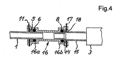
- the third embodiment of the fluid line connection arrangement shown in FIG. 4 is still significantly less expensive to manufacture.
- the outer diameter of the bead 14 is approximately the same as the average diameter of the O-ring 8, against which the bead 14 is mounted in the assembled state of the fluid line connection arrangement directly supported.
- a spring clip 17 is inserted into a slot receptacle 18 of a connecting sleeve portion 16b.
- the spring clip 17 and the slot receptacle 18 and the connecting sleeve section 1 6b are formed like the spring clip 12 and the slot receptacle 10 and the connecting sleeve section 4b of the first and second embodiments, except that they can be adapted to the larger outer diameter of the metallic connecting line 15.
- connecting part 16 with the connecting sleeve portion 16a connecting the first line 1 to the second line 15 are the same as described above for the connecting part 4 and the connecting sleeve portion 4a of the first embodiment according to FIG Reference is made.
- the latter also applies to the first line 1 with the lasered connection sleeve 5 and its function together with the O-ring 6 and the spring clip eleventh
Abstract
Description
Die Erfindung betrifft eine Fluidleitungsverbindungsanordnung nach dem Oberbegriff des Anspruchs 1.The invention relates to a fluid line connection arrangement according to the preamble of
In einer Fluidleitungsverbindungsanordnung nach der
In einer zweiten und dritten Ausführungsform der Fluidleitungsverbindungsanordnung ist das Halteelements als Sprengring bzw. Federring ausgebildet, der eine umlaufende Nut in der Muffe weitgehend umschließt und durch Eingriff einer Zange in Löcher an den Ringenden und Zusammenziehen der Ringenden aus der Nut entfernt werden kann.In a second and third embodiment of the fluid line connection arrangement, the retaining element is formed as a snap ring which largely encloses a circumferential groove in the sleeve and can be removed by engaging a pair of pliers in holes on the ring ends and contraction of the ring ends of the groove.
In der dritten Ausführungsform ist zusätzlich ein Dichtungsdistanzstück vorgesehen, welches durch die Stirnseite der Muffe gegen den O-Ring gedrückt wird, der wie bei der zweiten Ausführungsform in einer Vertiefung des Rohrs neben dessen wulstförmiger Erweiterung liegt.In addition, in the third embodiment, there is provided a sealing spacer which is pressed by the end face of the sleeve against the O-ring, which, as in the second embodiment, lies in a recess of the tube adjacent to its bulbous enlargement.
Alle Ausführungsformen der bekannten Fluidleitungsverbindungsanordnung weisen eine verhältnismäßig komplizierte Formgebung insbesondere hinsichtlich der Aufbohrung des sogenannten Gehäuses auf, die fertigungsungünstig ist. Weiterhin ist das federnde Verbindungselement, welches die voneinander lösbaren Teile der Fluidleitungsverbindungsanordnung zusammenhalten soll, räumlich nicht kompakt, fertigungsaufwendig und im Bedarfsfall schwierig aus der Bohrung des Gehäuses zu entfernen, da dazu eine Zange in die Löcher der Zungen des Verbindungselements eingreifen muss, was in der Regel ein spezielles Werkzeug erfordert. Im wesentlichen die gleichen Nachteile hat auch das alternative Halteelement in Form eines Sprengrings bzw. Federrings, der in eine außen umlaufende Nut in der Muffe eingreift und diese weitgehend umschließt. Der Sprengring bzw. Federring kann ebenfalls nur durch Eingriff eines Werkzeugs bzw. einer Zange in Löcher an den Ringenden aus der Nut entfernt werden. Alle Ausführungsformen umfassen die auf das Rohrende aufgeschobene Muffe, die allenfalls zwischen zwei wulstförmigen Erweiterungen des Rohrendes gehalten wird und die mit einer ihrer Stirnseiten unmittelbar oder mittelbar über das Dichtungsdistanzstück den O-Ring gegen die Schulter der Bohrung in dem Gehäuse drückt, um die Abdichtung der Fluidleitungsverbindungsanordnung nach außen herzustellen. Somit dient keine wulstförmige Erweiterung als Dichtungselement, die dafür einen im Verhältnis zu dem mittleren Durchmesser des O-Rings zu kleinen Außendurchmesser aufweist.All embodiments of the known fluid line connection arrangement have a relatively complicated shape, in particular with regard to the boring of the so-called housing, the production unfavorable is. Furthermore, the resilient connecting element, which is to hold together the detachable parts of the fluid line connection arrangement, spatially not compact, production-consuming and, if necessary, difficult to remove from the bore of the housing, as to a pliers must engage in the holes of the tongues of the connecting element, which in the Usually requires a special tool. Substantially the same disadvantages also have the alternative retaining element in the form of a snap ring or spring ring, which engages in an outer circumferential groove in the sleeve and this largely encloses. The snap ring or spring ring can also be removed only by engagement of a tool or a pair of pliers in holes at the ring ends of the groove. All embodiments include the pushed onto the pipe end sleeve, which is held at most between two bulbous extensions of the pipe end and presses with one of its faces directly or indirectly via the sealing spacer the O-ring against the shoulder of the bore in the housing to the sealing of the Fluid line connection arrangement to produce to the outside. Thus, no bead-shaped extension serves as a sealing element, which has a small outer diameter in relation to the mean diameter of the O-ring.
Um eine Fluidleitungsverbindungsanordnung zu schaffen, die mit unkompliziert herstellbaren Verbindungselementen und rasch durchführbaren Verbindungsvorgängen auskommt und gleichwohl eine gute Abdichtung der miteinander verbundenen Leitungen nach außen aufweist, ist bereits eine Fluidleitungsverbindungsanordnung gemäß dem Oberbegriff des Anspruchs 1 bzw. 2 bekannt (
Zum sicheren form- und kraftschlüssigen Aufbringen der Verbindungsmuffe auf dem Endabschnitt eines Schlauchs, der eine zu verbindende Leitung darstellt, kann die Verbindungsmuffe aus einem ringförmigen Außenschlauchabschnitt aus einem laserstrahldurchlässigen, insbesondere thermoplastischen Kunststoff und einem mit diesem koextrudierten ringförmigen Innenschlauchabschnitt aus einem laserstrahlabsorbierenden schweißbarem, insbesondre thermoplastischen Kunststoff bestehen (
Die vorliegende Erfindung beruht auf der besonderen Problematik, flexible Schlauchleitungen mit starren metallischen Anschlussleitungen von Durchlauferhitzern in Kaffee- und Espressomaschinen druck- und flüssigkeitsdicht lösbar zu verbinden, wobei den unterschiedlichen Materialien, dem hohen Druck und der hohen Temperatur sowohl des metallischen Durchlauferhitzers als auch des durch die Fluidleitungsverbindungsanordnung geleiteten erhitzten Brühwassers Rechnung zu tragen ist. Hinzu kommt die gewünschte leichte Montierbarkeit und - im Servicefall - Demontierbarkeit der Fluidleitungsverbindungsanordnung.The present invention is based on the particular problem, pressure and liquid-tight releasably connect flexible hose assemblies with rigid metallic leads of water heaters in coffee and espresso machines, the different materials, the high pressure and high temperature of both the metallic water heater and by the fluid line connection arrangement directed heated brewing water is taken into account. Added to this is the desired ease of assembly and - in case of service - disassembly of the fluid line connection assembly.
In der Praxis wurden bisher für die Verbindung zwischen der flexiblen Schlauchleitung und dem metallischen Anschlussrohr bzw. der starren metallischen Anschlussleitung des Durchlauferhitzers metallische Schraub-/Quetschverbindungen verwendet, bei denen sich ein innerhalb einer Überwurfmutter liegender Metallring durch den Schraubdruck der Überwurfmutter in die metallische Anschlussleitung des Durchlauferhitzers kerbt und damit verankert. Nachteilig ist bei dieser Verbindung unter anderem der Fertigungsaufwand für die Überwurfmuttern mit Metallring und der Montageaufwand bei der Herstellung der Verbindung.In practice, metallic screw / crimp connections have hitherto been used for the connection between the flexible hose line and the metallic connecting pipe or the rigid metallic connecting line of the water heater, in which a metal ring lying within a union nut is screwed into the metallic connecting line of the screw Throughflow heater notches and anchored. A disadvantage of this compound, inter alia, the production cost of the union nuts with metal ring and the assembly costs in the preparation of the compound.
Der vorliegenden Erfindung liegt daher die Aufgabe zugrunde, eine unkomplizierte, rasch montierbare Fluidleitungsverbindungsanordnung zu schaffen, die im Bedarfsfall mehrfach gelöst und zuverlässig dicht zusammengesetzt werden kann und speziell zur Verbindung von druck- und flüssigkeitsdichten flexiblen Schlauchleitungen mit starren metallischen Anschlussleitungen von Durchlauferhitzern in Kaffee- und Espressomaschinen vorgesehen ist.The present invention is therefore an object of the invention to provide an uncomplicated, quickly assembled fluid line connection arrangement, which can be solved several times in case of need and reliably sealed together and especially for the connection of pressure and liquid densities flexible hoses with rigid metallic connecting lines of water heaters in coffee and espresso machines is provided.
Eine Lösung dieser Aufgabe steiit die Fluidleitungsverbindungsanordnung mit einer Kombination der Merkmale des Anspruchs 1 dar.A solution to this problem steiit the fluid line connection arrangement with a combination of the features of
Eine zweite Lösung der Aufgabe besteht in einer Kombination der Merkmale der Fluidleitungsverbindungsanordnung nach Anspruch 2.A second solution of the object consists in a combination of the features of the fluid line connection arrangement according to
Beide Lösungen beruhen auf einer Fluidleitungsverbindungsanordnung mit einem Verbindungsglied, welches zwei äußere Verbindungshülsenabschnitte aufweist, aus denen jeweils innen eine ringförmige Schulter ausgebildet ist und welches eine erste Leitung aus flexiblem Kunststoff mit einer zweiten Leitung verbindet, wobei jeweils auf einem durchgehend zylindrischen Endabschnitt der ersten Leitung und der zweiten Leitung in einem Abstand von einem Ende der ersten Leitung bzw. der zweiten Leitung eine Verbindungsmuffe, die innen durchgehend zylindrisch ist und eine vordere ringförmige Stirnseite sowie eine hintere ringförmige Stirnseite aufweist, wobei an jedem der Verbindungshülsenabschnitte jeweils eine Federklammer als Arretierungselement lösbar anbringbar ist, welches durch jeweils innen seitlich offene Schlitzaufnahmen in einem der Verbindungshülsenabschnitte reicht und an der hinteren ringförmigen Stirnseite einer der in einen der Verbindungshülsenabschnitte eingesteckten Verbindungsmuffen anliegt, und wobei jeweils eine vordere ringförmige Stirnseite des Verbindungsmuffenabschnitts mittelbar oder unmittelbar an der ringförmigen Schulter einer der Verbindungshülseabschnitte anliegt, wobei jeweils ein O-Ring zwischen der ringförmigen Schulter jedes der Verbindungshülsenabschnitte und der vorderen ringförmigen Stirnseite einer der Verbindungsmuffen eingeschlossen ist. Die zweite Leitung ist dabei eine starre metallische Anschlussleitung eines Durchlauferhitzers, auf die eine metallische Verbindungsmuffe aufgelötet ist.Both solutions are based on a fluid line connection arrangement with a connecting member, which has two outer connecting sleeve portions, each of which an annular shoulder is formed and which connects a first line made of flexible plastic with a second line, wherein each on a continuous cylindrical end portion of the first line and the second conduit at a distance from one end of the first conduit and the second conduit, a coupling sleeve which is cylindrical inside and has a front annular end side and a rear annular end side, wherein each of the Verbindungshülsenabschnitte a spring clip is releasably attachable as a locking element which extends through in each case laterally open slot receivers in one of the connecting sleeve sections and at the rear annular end side of one of the connecting sleeve sections inserted Ver each of a front annular end face of the coupling sleeve portion abuts directly or indirectly on the annular shoulder of one of the Verbindungshülseabschnitte, each having an O-ring between the annular shoulder of each of the Verbindungshülsenabschnitte and the front annular end of one of the coupling sleeves is included. The second line is a rigid metallic connecting cable a water heater to which a metal coupling sleeve is soldered.
Bei der ersten Lösung besteht weiterhin ein Kombinationsmerkmal darin, dass - wie an sich bekannt - die Verbindungsmuffe der ersten Leitung aus flexiblem Kunststoff einen ringförmigen Außenschlauchabschnitt aus einem laserstrahldurchlässigen, insbesondere thermoplastischen Kunststoff und einen mit diesem koextrudierten ringförmigen Innenschlauchabschnitt aus einem laserstrahlabsorbierenden schweißbaren, insbesondere thermoplastischen Kunststoff umfasst und dass die Verbindungsmuffe auf den Endabschnitt der ersten Leitung aus schweißbarem, insbesondere thermoplastischem Kunststoff gelasert ist.In the first solution, a combination feature further consists in that - as is known - the connection sleeve of the first flexible plastic conduit an annular outer tube portion of a laserstrahldurchlässigen, in particular thermoplastic and an co-extruded with this annular inner tube portion of a laser beam absorbing weldable, especially thermoplastic plastic comprises and that the coupling sleeve is lasered onto the end portion of the first conduit made of weldable, in particular thermoplastic plastic.
Diese Lösung hat den Vorteil, dass in dem Endabschnitt der ersten Leitung aus flexiblem Kunststoff kein Stützrohr vorgesehen zu sein braucht, da bei der Anbringung der Verbindungsmuffe auf den Endabschnitt der ersten Leitung keine erheblichen Drücke ausgeübt werden.This solution has the advantage that in the end portion of the first conduit of flexible plastic no support tube needs to be provided, as in the attachment of the coupling sleeve on the end portion of the first line no significant pressures are exerted.
Gemäß der zweiten Lösung wird statt der aufgelaserten Verbindungsmuffe aus Kunststoff eine metallische Verbindungsmuffe auf den Endabschnitt der ersten Leitung aufgequetscht, wozu in dem Endabschnitt ein Stützrohr eingeschoben ist, um eine einfache, zuverlässige und dichte Quetschverbindung zu gewährleisten.According to the second solution, a metallic connecting sleeve is crimped onto the end portion of the first conduit instead of the lasered plastic connecting sleeve, for which purpose a support tube is inserted in the end portion in order to ensure a simple, reliable and tight crimp connection.
Bei beiden erfindungsgemäßen Lösungen wird sowohl das Schlauchende, d.h. der Endabschnitt der ersten Leitung, mit der an ihm angebrachten Verbindungsmuffe und einem aufgesteckten O-Ring, als auch die metallische Anschlussleitung mit der auf sie aufgelöteten metallischen Verbindungsmuffe jeweils in einen der beiden äußeren Verbindungshülsenabschnitte des Verbindungsteils gesteckt und mittels einer der Federklammern, die jeweils durch die Schlitzaufnahmen in einen der Verbindungshülsenabschnitte gesteckt werden, arretiert. Im Betriebszustand der Kaffee- oder Espressomaschine, die mit dieser Fluidleitungsverbindungsanordnung ausgestattet ist, übernehmen die O-Ringe die gesicherte Abdichtungsfunktion, während die Federklammern den in den Leitungen und in dem Verbindungsteil herrschenden Druck aufnehmen.In both solutions according to the invention, both the end of the hose, ie the end portion of the first line, with the attached coupling sleeve and an attached O-ring, as well as the metallic connecting line with the soldered metallic coupling sleeve in each case in one of the two outer connecting sleeve portions of the connecting part plugged in and by means of one of the spring clips, respectively are inserted through the slot recordings in one of the connecting sleeve sections, locked. In the operating state of the coffee or espresso machine equipped with this fluid line connection arrangement, the O-rings take over the secure sealing function, while the spring clips absorb the pressure prevailing in the lines and in the connecting part.
Eine dritte Lösungsvariante geht von einer Fluidleitungsverbindungsanordnung gemäß dem Oberbegriff des Anspruchs 3 aus und umfasst die Kombination der Merkmale des Anspruchs 3.A third variant of the solution starts from a fluid line connection arrangement according to the preamble of
Zu dessen Merkmalen gehört insbesondere die Gestaltung des Endabschnitts der starren metallischen Anschlussleitung eines Festteils bzw. des Durchlauferhitzers, aus dem ein umlaufender Wulst als ringförmiges Verbindungselement durch Stauch-/Rollbearbeitung einstückig mit dem Rohr ausgeformt ist.Its characteristics include in particular the design of the end portion of the rigid metallic connecting line of a fixed part or the flow heater, from which a circumferential bead is formed as an annular connecting element by upset / roll machining integral with the tube.
Bei dieser besonders fertigungsgünstigen Realisierung des Verbindungselements braucht dieses also nicht gesondert vorgefertigt und auf dem Endabschnitt der Anschlussleitung rundum dicht angebracht zu werden, damit eine Leckage über den Außenumfang des Endabschnitts ausgeschlossen ist. Denn der O-Ring dichtet vor allem an der ringförmigen Kontaktzone ab, an der er unter Anpressdruck an der vorderen Stirnseite des Verbindungselements steht, sowie an einer außen gegenüberliegenden ringförmigen Kontaktzone an der ringförmigen Schulter des Verbindungshülsenabschnitts, in dem er angeordnet ist. Weiterhin ist im Vergleich zu einer Fluidleitungsverbindungsanordnung nach dem Stand der Technik mit einer auf den Endabschnitt der zweiten Leitung bzw. eines Rohrs aufgeschobenen Muffe, die auf diesem durch zwei flache wulstförmige Erweiterungen oder nur eine derartige Erweiterung des Rohrs provisorisch gehalten wird, bis der Endabschnitt in das am Ende der ersten Leitung ausgeformten Gehäuse eingesteckt ist und durch das Halteelement gehalten ist, die Montage der erfindungsgemäßen Fluidleitungsverbindungsanordnung wesentlich vereinfacht.In this particularly low-production realization of the connecting element this does not need to be separately prefabricated and mounted on the end portion of the connecting line all around tightly, so that leakage is excluded over the outer periphery of the end portion. Because the O-ring seals above all at the annular contact zone, where it is under contact pressure at the front end side of the connecting element, and at an outer opposite annular contact zone on the annular shoulder of the connecting sleeve portion in which it is arranged. Further, as compared with a prior art fluid line connector assembly with a sleeve slid onto the end portion of the second conduit or tube provisionally held thereon by two flat bead-shaped extensions or only such an extension of the tube, the end portion is inserted into the housing formed at the end of the first line and is held by the holding element, the assembly of the fluid line connection arrangement according to the invention substantially simplified.
Bemerkenswert ist weiterhin die kompakte Ausbildung der erfindungsgemäßen Fluidleitungsverbindungsanordnung insbesondere in axialer Richtung, die durch den schmalen umlaufenden Wulst nach Anspruch 3 ermöglicht ist. Hierzu trägt auch die Federklammer bei, die in die Verbindungsmuffe zur Vollendung der Fluidleitungsverbindung einfach eingesteckt wird.Also noteworthy is the compact design of the fluid line connection arrangement according to the invention, in particular in the axial direction, which is made possible by the narrow circumferential bead according to
Zur nach außen fluiddichten Verbindung, die wie oben erwähnt mit der erfindungsgemäßen Ausbildung der Fluidleitungsverbindungsanordnung besonders zuverlässig erzielt werden kann, ist der Außendurchmesser des aus dem Endabschnitt der starren Anschlussleitung ausgeformten umlaufenden Wulstes gemäß Anspruch 4 mindestens so groß wie der mittlere Durchmesser des O-Rings, an dem er mit seiner vorderen Stirnseite im montierten Zustand der Fluidleitungsverbindungsanordnung anliegt, um an beiden Stirnseiten des O-Rings ringförmige Kontaktzonen bzw. Dichtzonen zu bilden. Entsprechend diesem Durchmesserverhältnis kann der O-Ring bei gegebenem umlaufenden Wulst gewählt werden.For outwardly fluid-tight connection, which can be achieved particularly reliable as mentioned above with the inventive design of the fluid line connection arrangement, the outer diameter of the formed from the end portion of the rigid connecting line circumferential bead according to
Der zur Erzielung guter Abdichtung der Fluidleitungsverbindungsanordnung noch gut geeignete kleinste Durchmesser des umlaufenden Wulstes ist gemäß Anspruch 5 ungefähr so groß wie der mittlere Durchmesser des O-Rings, oder mit anderen Worten, der mittlere Durchmesser des O-Rings ist ungefähr gleich groß wie der Außendurchmesser der umlaufenden Nut gewählt. Dementsprechend kann der Außenumfang der Fluidleitungsverbindungsanordnung minimiert werden.The minimum diameter of the circumferential bead still well suited for achieving good sealing of the fluid line connection arrangement is approximately as large as the average diameter of the O-ring, or in other words, the average diameter of the O-ring is approximately equal to the outer diameter the circumferential groove chosen. Accordingly, the outer circumference of the fluid passage connecting structure can be minimized.
Die gemäß den Ansprüchen 3 - 5 gestaltete bzw. dimensionierte Fluidleitungsverbindungsanordnung ist daher besonders für dünne Anschlussleitungen geeignet, wie sie an Durchlauferhitzern für Kaffeemaschinen typisch sind.The designed according to claims 3 - 5 or dimensioned fluid line connection arrangement is therefore particularly suitable for thin connection lines, as they are typical of instantaneous water heaters for coffee machines.
Die Fluidleitungsverbindungsanordnung gemäß den Ansprüchen 3 - 5, die als so bezeichnete zweite Leitung eine metallische Anschlussleitung eines Festteils bzw. Durchlauferhitzers aufweist, aus deren Endabschnitt ein umlaufender Wulst durch Stauch-/Rollbearbeitung ausgeformt ist, kann eine erste Leitung aufnehmen, die gemäß Anspruch 6 eine Verbindungsmuffe aufweist, welche einen ringförmigen Außenschlauchabschnitt aus einem laserstrahldurchlässigen, insbesondere thermoplastischen Kunststoff und einen mit diesem koextrudierten ringförmigen Innenschlauchabschnitt aus einem laserstrahlabsorbierenden schweißbaren, insbesondere thermoplastischen Kunststoff umfasst, wobei die Verbindungsmuffe auf den Endabschnitt der ersten Leitung aus schweißbarem, insbesondere thermoplastischem Kunststoff gelasert ist. Dazu ist die Laserstrahlabsorption des Innenschlauchabschnitts bei der Herstellung dessen Kunststoffmaterials gezielt eingestellt.The fluid line connection arrangement according to claims 3-5, which has a metallic connecting line of a fixed or continuous heater, from the end portion of which a peripheral bead is formed by swaging, can receive a first line, which according to claim 6 a Connecting sleeve, which comprises an annular outer tube portion of a laser beam permeable, especially thermoplastic plastic and a co-extruded with this annular inner tube portion of a laser beam absorbing weldable, especially thermoplastic plastic, wherein the coupling sleeve is lasered onto the end portion of the first conduit made of weldable, in particular thermoplastic plastic. For this purpose, the laser beam absorption of the inner tube section in the production of its plastic material is specifically adjusted.
Alternativ kann die genannte Fluidleitungsverbindungsanordnung gemäß den Ansprüchen 3-5 vielseitig auch eine erste Leitung aus flexiblem Kunststoff aufnehmen, in deren Endabschnitt nach Anspruch 7 ein Stützrohr eingeschoben ist, wobei eine metallische Verbindungsmuffe auf den Endabschnitt der ersten Leitung aufgequetscht ist.Alternatively, said fluid line connection arrangement according to claims 3-5 can also accommodate in a versatile manner a first line of flexible plastic, in the end section of claim 7 a support tube is inserted, wherein a metallic coupling sleeve is crimped onto the end portion of the first line.
Die Ansprüche 8-16 beinhalten weitere vorteilhafte Ausgestaltungen der Fluidleitungsverbindungsanordnung.The claims 8-16 include further advantageous embodiments of the fluid line connection arrangement.
Eine Realisierung des die beiden Verbindungshülsenabschnitte aufweisenden Verbindungsteils als Kunststoffspritzteil gemäß Anspruch 8 ist besonders herstellungsgünstig.An implementation of the two connecting sleeve sections having connecting part as a plastic injection molded part according to
Die gemäß Anspruch 9 annähernd U-förmige Federklammer mit zwei im wesentlichen parallelen, gewellten Schenkeln, deren äußere Abschnitte eine sich nach innen verjüngende Öffnung bilden, an die sich nach innen eine Leitungsaufnahmeausbuchtung anschließt, ist nicht nur herstellungsgünstig, sie kann darüber hinaus einfach ohne Werkzeug in der Fluidleitungsverbindungsanordnung montiert werden und nimmt gleichwohl betriebsmäßig den Innendruck in den Leitungen und der Fluidleitungsverbindungsanordnung zuverlässig auf. Im Bedarfsfall kann die Federklammer leicht gelöst werden. Zur Herstellung der Fluidleitungsverbindungsanordnung werden zwei solcher Federklammern eingesetzt.The approximately according to
Für die Schlitzaufnahmen in den Verbindungshülsenabschnitten sind zwei Ausführungen möglich: Wenn die Schlitzaufnahmen gemäß Anspruch 11 nicht nur innen, sondern auch seitlich offen sind, ermöglicht dies eine einfache Fertigung der Verbindungshülse und eine besonders einfache Handhabung der Federklammer zur Arretierung oder zum Lösen der Fluidleitungsverbindung.For the slot receptacles in the connecting sleeve sections, two versions are possible: If the slot holders according to claim 11 not only inside, but also laterally open, this allows easy production of the connecting sleeve and a particularly simple handling of the spring clip for locking or to release the fluid line connection.
Sind hingegen die Schlitzaufnahmen der Verbindungshülsenabschnitte gemäß Anspruch 10 außen seitlich geschlossen, so können die Federklammern weitgehend in ihnen verschwinden und in ihnen auch dann sicher gehalten werden, wenn auf die Federklammern so große Kräfte durch den Innendruck in den Leitungen und in der Fluidleitungsverbindung ausgeübt werden.If, however, the slot receivers of the connecting sleeve sections according to claim 10 closed laterally outside, so the spring clips can largely disappear in them and are held securely in them even if so great forces are exerted on the spring clips by the internal pressure in the lines and in the fluid line connection.
Die Verbindungsmuffe, wie sie jeweils für die erste Leitung aus flexiblem Kunststoff der Fluidleitungsverbindung vorgesehen ist, wird von einem koextrudierten Schlauch abgelängt, der einen Innenschlauch und einen Außenschlauch umfasst. Zweckmäßig basieren die Materialien des Außenschlauchs bzw. nach Anspruch 12 des ringförmigen Außenschlauchabschnitts und des Innenschlauchs bzw. des ringförmigen Innenschlauchabschnitts auf dem gleichen laserstrahldurchlässigen Kunststoff, wobei der Kunststoff des ringförmigen Innenschlauchabschnitts aber laserabsorbierend modifiziert ist. Dies ermöglicht eine unproblematische Koextrusion, als deren Ergebnis der Außenschlauch fest und dicht auf dem Innenschlauch sitzt.The coupling sleeve, as provided respectively for the first conduit of flexible plastic of the fluid line connection, is cut to length by a coextruded tube comprising an inner tube and an outer tube. Suitably, the materials of the outer tube or according to claim 12 of the annular outer tube portion and the inner tube or the annular inner tube portion on the same laser-beam-permeable plastic, wherein the plastic of the annular inner tube portion but is laser-absorbent modified. This allows for unproblematic coextrusion, as a result of which the outer tube sits firmly and tightly on the inner tube.
Die Materialangaben und daraus resultierten Eigenschaften des Außenschlauchs und des Innenschlauchs des koextrudierten Kunststoffschlauchs gelten analog für den ringförmigen Außenschlauchabschnitt und ringförmigen Innenschlauchabschnitt der Verbindungsmuffe, die aus dem koextrudierten Kunststoffschlauch hergestellt werden.The material specifications and resulting properties of the outer tube and the inner tube of the coextruded plastic tube apply analogously to the annular outer tube section and annular inner tube section of the connecting sleeve, which are made from the coextruded plastic tube.
Gemäß Anspruch 1 3 ist der Kunststoff des Innenschlauchs vorteilhaft einfach laserstrahlabsorbierend eingefärbt, wodurch die übrigen Materialeigenschaften des Kunststoffs nicht beeinträchtigt werden.According to
Besonders bewährt hat sich nach Anspruch 14 als thermoplastisches Material des Innenschlauchs ein laserstrahldurchlässiger Kunststoff, in dem Russpartikel zur Laserstrahlabsorption möglichst gleichmäßig verteilt sind.Has proven particularly useful according to claim 14 as a thermoplastic material of the inner tube, a laser-beam-permeable plastic, are distributed as uniformly as possible in the soot particles for laser beam absorption.
Hierzu hat sich gemäß Anspruch 1 5 ein Gewichtsanteil der Russpartikel in dem Kunststoff des Innenschlauchs von 1 - 2 % als ausreichend herausgestellt.For this purpose, a proportion by weight of soot particles in the plastic of the inner tube of 1 - 2% has been found sufficient according to
Die Wandstärke des Innenschlauchs soll ausreichend sein, um eine genügende Laserstrahlabsorption für eine Verschweißung bzw. Verschmelzung mit dem Kunststoff des Schlauchs der ersten Leitung der Fluidverbindung zu gewährleisten. Gemäß Anspruch 16 ist eine Wanddicke von 0,2 - 0,3 mm ausreichend. Dabei kann der koextrudierte Schlauch überwiegend aus laserstrahldurchlässigem Kunststoff bestehen, der nicht laserstrahlabsorbierend modifiziert ist.The wall thickness of the inner tube should be sufficient to ensure sufficient laser beam absorption for welding or fusion with the plastic of the tube of the first conduit of the fluid connection. According to
Drei Ausführungsbeispiele der Erfindung werden im folgenden anhand einer Zeichnung mit vier Figuren erläutert, woraus sich weitere vorteilhafte Merkmale ergeben können. Es zeigt:
Figur 1- einen Längsschnitte durch eine erste Ausführungsform der Fluidleitungsverbindungsanordnung, die als Steckverbindung einer flexiblen Kunststoffleitung mit einer aufgelaserten Verbindungsmuffe ausgeführt ist und die mit einer starren metallischen Anschlussleitung eines Durchlauferhitzers verbunden ist,
Figur 2- einen Längsschnitt durch eine zweite Ausführungsform der Fluidleitungsverbindungsanordnung einer flexiblen Kunststoffleitung, die eine metallische Verbindungsmuffe aufweist und die mit der starren metallischen Anschlussleitung eines Durchlauferhitzers verbunden ist,
Figur 3- eine Explosionsdarstellung der Fluidleitungsverbindungsanordnung gemäß Figur 1, wobei die
Fluidleitungsverbindungsanordnung nach Figur 2 insoweit gleich aussehen kann, und Figur 4- einen Längsschnitt durch eine dritte Ausführungsform der Fluidleitungsverbindungsanordnung einer flexiblen Kunststoffleitung gemäß Figur 1 sowie einer starren metallischen Anschlussleitung eines Durchlauferhitzers, in deren Endabschnitt ein umlaufender Wulst durch Stauch-/Rollbearbeitung ausgeformt ist.
Die starre metallische Anschlussleitung mit dem umlaufenden Wulst kann in einer weiteren Ausführungsform, die nicht gezeigt ist, auch mit einer flexiblen Kunststoffleitung nach Fig. 2 kombiniert werden.
- FIG. 1
- a longitudinal section through a first embodiment of the fluid line connection assembly, which is designed as a plug connection of a flexible plastic conduit with a lasered connection sleeve and which is connected to a rigid metallic connecting line of a water heater,
- FIG. 2
- a longitudinal section through a second embodiment of the fluid line connection assembly of a flexible plastic conduit having a metallic connecting sleeve and which is connected to the rigid metallic connecting line of a water heater,
- FIG. 3
- an exploded view of the fluid line connection arrangement according to Figure 1, wherein the fluid line connection arrangement of Figure 2 can look the same extent, and
- FIG. 4
- a longitudinal section through a third embodiment of the fluid line connection arrangement of a flexible plastic conduit according to Figure 1 and a rigid metallic Connecting line of a water heater, in the end portion of a circumferential bead is formed by compression / rolling machining.
The rigid metallic connecting line with the encircling bead can also be combined with a flexible plastic line according to FIG. 2 in a further embodiment, which is not shown.
In allen Figuren sind gleiche Teile mit übereinstimmenden Bezugszeichen versehen.In all figures, like parts are provided with corresponding reference numerals.
In beiden Ausführungsbeispielen der Fluidleitungsverbindungsanordnung nach den Figuren 1 - 3 wird eine flexible Kunststoffleitung als erste Leitung 1 mit einer starren metallischen Anschlussleitung als zweite Leitung 2, die Teil eines nur teilweise angedeuteten Durchlauferhitzers 3 ist, mittels eines Verbindungsteils 4 verbunden, welches zwei einander entgegengesetzten Enden offene Verbindungshülsenabschnitte 4a, 4b aufweist, die gleiche Formmerkmale aufweisen und durch einen Leitungsabschnitt 4c miteinander verbunden sind.In both exemplary embodiments of the fluid line connection arrangement according to FIGS. 1-3, a flexible plastic line is connected as the
Auf die erste Leitung 1 ist an einem Endabschnitt kurz vor ihrem verbindungsseitigen Ende eine Verbindungsmuffe 5 aufgelasert, die der Fixierung der ersten Leitung 1 in den Verbindungshülsenabschnitt 4a des Verbindungsteils 4 dient.On the
Die hierzu verwendete Verbindungsmuffe 5 aus Kunststoff ist ein Abschnitt eines koextrudierten Schlauchs mit einem ringförmigen Innenschlauchabschnitt und einem ebenso ringförmigen Außenschlauchabschnitt und ist von einem solchen koextrudierten Schlauch abgelängt. Der Innenschlauchabschnitt und der Außenschlauchabschnitt sind in Figur 1 nicht getrennt dargestellt.The
Die Verbindungsmuffe 5 besteht aus einem Copolymer, insbesondere Tetrafluormethylen oder Hexafluorpropylen. Das Copolymer ist normalerweise laserstrahldurchlässig und transparent. In dieser Form bildet es den ringförmigen Außenschlauchabschnitt der Verbindungsmuffe. Hingegen weist zur Laserstrahlenabsorption der Kunststoff des Innenschlauchabschnitts einen Russanteil von 1 - 2 Gewichtsprozent auf; er ist schwarz. Der Innenschlauchabschnitt ist durch die Co-Extrusion des Schlauchs mit dem Außenschlauch form- und kraftschlüssig verbunden. Der Innenschlauch ist mit einer typischen Wanddicke von 0,25 mm ausreichend dick, um nach dem Aufbringen der Verbindungsmuffe 5 auf dem Endabschnitt der ersten Leitung 1 mit vorne herausragendem Schlauchende in einem Werkzeug unter Laserstrahlabsorption genügend erwärmt zu werden und mit dem innen anliegenden Endabschnitt verschweißt zu werden. Der Außenschlauchabschnitt kann eine mehrfach größere Wandstärke als der Innenschlauchabschnitt aufweisen, um mechanisch widerstandsfähig zu sein. Beide Schlauchabschnitte der Verbindungsmuffe 5 bilden zusammen eine nicht bezeichnete ringförmige Stirnseite, an der ein O-Ring 6 als Dichtelement anliegen kann.The
Auf der metallischen Anschlussleitung 2 des Durchlauferhitzers 3 wird hingegen eine Verbindungsmuffe 7 aus Metall aufgelötet und ist damit in anderer Weise form- und kraftschlüssig mit der metallischen Anschlussleitung 2 verbunden als die Verbindungsmuffe 5 aus Kunststoff mit der ersten Leitung 1.On the other hand, a connecting
Nach dem Aufbringen der Verbindungsmuffen 5 und 7 auf der ersten Leitung 1 bzw. der zweiten Leitung 2 kann eine Verbindung der beiden Leitungen mittels des Verbindungsteils 4 erfolgen. Hierzu werden die Enden der ersten Leitung 1 mit der Verbindungsmuffe 5 und dem O-Ring 6 in den Verbindungshülsenabschnitt 4a geschoben und in das Ende der zweiten Leitung 2 mit der Verbindungsmuffe 7 und einem weiteren O-Ring 8 in den Verbindungshülsenabschnitt 4b.After applying the connecting
Zur Verbindung der Verbindungshülsenabschnitte 4a, 4b mit der ersten Leitung 1 als flexible Kunststoffleitung und mit der zweiten Leitung 2 als metallische Anschlussleitung sind aus den Verbindungshülsenabschnitte 4a, 4b Schlitzaufnahmen 9, 10 ausgeformt, die innen seitlich offen sind, siehe Figuren 1 und 2, jedoch außen seitlich geschlossen sind, siehe Figur 3.To connect the connecting
Eine in Figur 3 erkennbare Öffnung auf der Oberseite der flach quaderförmigen Enden der Verbindungshülsenabschnitte verläuft im wesentlichen rechtwinklig zwischen den beiden in dieser Figur nicht gezeigten seitlichen Schlitzaufnahmen.An opening, which can be seen in FIG. 3, on the upper side of the flatly parallelepiped-shaped ends of the connecting sleeve sections runs essentially at right angles between the two lateral slot receptacles (not shown in this figure).
Nachdem die Enden der ersten Leitung 1 und der zweiten Leitung 2 in dem Verbindungsteil 4 unter Einschluss der O-Ringe 6, 8 eingeschoben sind, erfolgt die feste aber lösbare Verbindung durch Einschieben jeweils einer Federklammer 10 bzw. 11, in die Schlitzaufnahmen 8 bzw. 9. Die Federklammer wird mit ihrem offenen erweiterten Ende in die zugeordneten Schlitzaufnahmen 8 bzw. 9 ohne Werkzeug leicht eingeschoben und hält infolge der gewellten Formgebung ihrer beiden im wesentlichen parallelen Schenkel den Endabschnitt der ersten bzw. zweiten Leitung axial fixiert, wobei die Federklammer gegen die Verbindungsmuffe 5 bzw. 7 drückt und mit Hilfe des O-Rings 6 bzw. 8 eine fluiddichte Verbindung herstellt. Dabei liegt der O-Ring einerseits an einer nicht bezeichneten verbindungsseitigen Stirnseite der Verbindungsmuffe 5 bzw. 7 und andererseits an einer ebenfalls nicht bezeichneten Schulter an, an welcher der die beiden Verbindungshülsenabschnitte 4a und 4b verbindende Leitungsabschnitt 4c in einen die Verbindungsmuffe 5 bzw. 7 aufnehmenden Abschnitt größeren Innendurchmessers übergeht.After the ends of the
Hinsichtlich der Abdichtung sind die erste Ausführungsform gemäß Figur 1 und die zweite Ausführungsform gemäß Figur 2 gleichwirkend.With regard to the sealing, the first embodiment according to FIG. 1 and the second embodiment according to FIG. 2 have the same effect.
Beide Ausführungsformen zeichnen sich durch unkomplizierte, herstellungsgünstige Formgebung und problemlose Wiederverwendbarkeit im Wartungsfall aus.Both embodiments are characterized by straightforward, low-cost design and easy reuse in case of maintenance.
Noch signifikant herstellungsgünstiger ist die dritte Ausführungsform der Fluidleitungsverbindungsanordnung, die in Figur 4 gezeigt ist.The third embodiment of the fluid line connection arrangement shown in FIG. 4 is still significantly less expensive to manufacture.
In ihr ist die in den ersten und zweiten Ausführungsformen auf die so bezeichnete zweite Leitung bzw. metallische Anschlussleitung des Durchlauferhitzers 3 oder eines entsprechenden Festteils aufgelötete Verbindungsmuffe aus Metall durch einen umlaufenden, das heißt ringförmigen Wulst 14 ersetzt, der durch einen Stauch-/Rollvorgang direkt aus der zweiten Leitung, hier 15, die eine starre metallische Anschlussleitung bzw. ein Anschlussrohr ist, ausgeformt. Die Anschlussleitung 15 bzw. das Anschlussrohr ist in dem durch den Stauch-/Rollvorgang bearbeiteten, nicht bezeichneten Endabschnitt links neben dem Wulst 15 verjüngt, und zwar auf den Innendurchmesser des Verbindungsteils 16. Dementsprechend ist der mit dem Durchlauferhitzer verbundene Abschnitt der metallischen Anschlussleitung 1 5 größer.In her in the first and second embodiments to the so-called second line or metallic connecting line of the
Wie aus Figur 4 ersichtlich, ist der Außendurchmesser des Wulstes 14 etwa so groß wie der mittlere Durchmesser des O-Rings 8, gegen den sich der Wulst 14 im gezeigten montierten Zustand der Fluidleitungsverbindungsanordnung direkt abstützt. Hierzu ist eine Federklammer 17 in eine Schlitzaufnahme 18 eines Verbindungshülsenabschnitts 16b eingesteckt. Die Federklammer 17 und die Schlitzaufnahme 18 sowie der Verbindungshülsenabschnitt 1 6b sind wie die Federklammer 12 bzw. die Schlitzaufnahme 10 und der Verbindungshülsenabschnitt 4b der ersten und zweiten Ausführungsformen ausgebildet, abgesehen davon, dass sie an den größeren Außendurchmesser der metallischen Anschlussleitung 15 angepasst sein können.As can be seen in FIG. 4, the outer diameter of the
Im Übrigen sind Aufbau und Funktion des Verbindungsteils 16 mit dem Verbindungshülsenabschnitt 1 6a, das die erste Leitung 1 mit der zweiten Leitung 15 verbindet, die gleichen wie oben zu dem Verbindungsteil 4 und dem Verbindungshülsenabschnitt 4a der ersten Ausführungsform gemäß Figur 1 beschrieben, worauf hiermit ausdrücklich Bezug genommen wird. Letzteres gilt auch für die erste Leitung 1 mit der aufgelaserten Verbindungsmuffe 5 und deren Funktion zusammen mit dem O-Ring 6 und der Federklammer 11.Incidentally, structure and function of the connecting
- 11
- erste Leitung (flexible Kunststoffleitung)first line (flexible plastic line)
- 22
- zweite Leitung (metallische Anschlussleitung)second line (metallic connection line)
- 33
- Durchlauferhitzer (Festteil)Instantaneous water heater (fixed part)
- 44
- Verbindungsteilconnecting part
- 4a4a
- VerbindungshülsenabschnittConnection sleeve section
- 4b4b
- VerbindungshülsenabschnittConnection sleeve section
- 4c4c
- Leitungsabschnittline section
- 55
- aufgelaserte Verbindungsmuffe aus Kunststofflasered connection sleeve made of plastic
- 5'5 '
- aufgequetschte Verbindungsmuffe aus MetallCrimped connection sleeve made of metal
- 66
- O-RingO-ring
- 77
- aufgelötete Verbindungsmuffe aus Metallsoldered connection sleeve made of metal
- 88th
- O-RingO-ring
- 99
- Schlitzaufnahmen (Verbindungsmuffe-Aufnahmeschlitz)Slot Receivers (Coupling Sleeve Receiving Slot)
- 1010
- Schlitzaufnahmen (Verbindungsmuffe-Aufnahmeschlitz)Slot Receivers (Coupling Sleeve Receiving Slot)
- 1111
- Federklammerspring clip
- 1212
- Federklammerspring clip
- 1313
- Stützrohr (Gegendruckhülse)Support tube (counter pressure sleeve)
- 1414
- Wulstbead
- 1515
- zweite Leitung (metallische Anschlussleitung)second line (metallic connection line)
- 1616
- Verbindungsteilconnecting part
- 16a16a
- VerbindungshülsenabschnittConnection sleeve section
- 16b16b
- VerbindungshülsenabschnittConnection sleeve section
- 1717
- Federklammerspring clip
- 1818
- Schlitzaufnahmeslot recording
Claims (16)
wobei jeweils ein O-Ring (6, 8) zwischen der ringförmigen Schulter jedes der Verbindungshülsenabschnitte (4a, 4b) und der vorderen ringförmigen Stirnseite einer der Verbindungsmuffen (5, 7) eingeschlossen ist,
dadurch gekennzeichnet,
dass die zweite Leitung (2) eine starre metallische Anschlussleitung eines Durchlauferhitzers (3) ist, auf die eine metallische Verbindungsmuffe (7) aufgelötet ist,
dass die Verbindungsmuffe (5) der ersten Leitung einen ringförmigen Außenschlauchabschnitt aus einem laserstrahldurchlässigen, insbesondere thermoplastischen Kunststoff und einen mit diesem koextrudierten ringförmigen Innenschlauchabschnitt aus einem laserstrahlabsorbierenden schweißbaren, insbesondere thermoplastischen Kunststoff umfasst und
dass die Verbindungsmuffe (5) auf den Endabschnitt der ersten Leitung (1) aus schweißbarem, insbesondere thermoplastischem Kunststoff gelasert ist.A fluid line connection assembly comprising a connection part (4) having two outer connection sleeve sections (4a, 4b) each having an annular shoulder formed therein and connecting a first flexible plastic conduit (1) to a second conduit (2) each on a continuous cylindrical end portion of the first conduit (1) and the second conduit (2) at a distance from one end of the first conduit and the second conduit, a connecting sleeve (5, 7) which is internally continuous cylindrical and a front annular Has front side and a rear annular end face, positively and non-positively applied, wherein at each of the connecting sleeve sections (4a, 4b) each have a spring clip (11, 12) releasably attachable as a locking element, which by each inside laterally open slot receivers (9, 10) in one of the connecting sleeve sections (4a, 4b) and on the rear ring shaped end face of the plugged into one of the connecting sleeve sections connecting sleeves (5, 7) is present, and
wherein an O-ring (6, 8) is enclosed between the annular shoulder of each of the connecting sleeve portions (4a, 4b) and the front annular end of one of the coupling sleeves (5, 7),
characterized,
that the second line (2) is a rigid metallic cord of a flow heater (3) on which a metallic connecting sleeve (7) is soldered,
that the connecting sleeve (5) of the first conduit comprises an annular outer tube section made of a laser-beam-permeable, in particular thermoplastic, plastic and an annular inner tube section co-extruded therefrom comprising a laser-absorbable, weldable, in particular thermoplastic, plastic material and
that the connecting sleeve (5) is lasered onto the end section of the first line (1) made of weldable, in particular thermoplastic plastic.
wobei jeweils ein O-Ring (6, 8) zwischen der ringförmigen Schulter jedes der Verbindungshülsenabschnitte (4a, 4b) und der vorderen ringförmigen Stirnseite einer der Verbindungsmuffen (5', 7) eingeschlossen ist,
dadurch gekennzeichnet,
dass die zweite Leitung (2) eine starre metallische Anschlussleitung eines Durchlauferhitzers (3) ist, auf die eine metallische Verbindungsmuffe (7) aufgelötet ist,
dass in dem Endabschnitt der ersten Leitung (1) aus flexiblem Kunststoff ein Stützrohr (13) eingeschoben ist und
dass eine metallische Verbindungsmuffe (5') auf den Endabschnitt der ersten Leitung aufgequetscht ist.A fluid line connection assembly comprising a connection part (4) having two outer connection sleeve sections (4a, 4b) each having an annular shoulder formed therein and connecting a first flexible plastic conduit (1) to a second conduit (2) each on a continuous cylindrical end portion of the first conduit (1) and the second conduit (2) at a distance from one end of the first conduit and the second conduit, a coupling sleeve (5 ', 7) which is cylindrical inside and a front cylindrical has annular end face and a rear annular end face, positively and non-positively applied, wherein at each of the connecting sleeve sections (4a, 4b) each have a spring clip (11, 12) releasably attachable as a locking element, which by laterally open at the side slit receptacles (9 , 10) in one of the connecting sleeve sections (4a, 4b) and on the rear rin gförmigen end face of one of the inserted into one of the connecting sleeve sections connecting sleeves (5 ', 7) is present, and
each O-ring (6, 8) being enclosed between the annular shoulder of each of the connecting sleeve portions (4a, 4b) and the front annular end face of one of the coupling sleeves (5 ', 7),
characterized,
that the second line (2) is a rigid metallic cord of a flow heater (3) on which a metallic connecting sleeve (7) is soldered,
that in the end portion of the first line (1) made of flexible plastic, a support tube (13) is inserted and
that a metallic connecting sleeve (5 ') is crimped onto the end portion of the first conduit.
wobei jeweils ein O-Ring (6, 8) zwischen der ringförmigen Schulter jedes der Verbindungshülsenabschnitte (16a, 16b) und der vorderen ringförmigen Stirnseite der Verbindungsmuffe (5) bzw. des Verbindungselements (14) eingeschlossen ist,
dadurch gekennzeichnet,
dass die zweite Leitung (15) eine starre metallische Anschlussleitung eines Durchlauferhitzers (3) ist, aus deren Endabschnitt ein umlaufender Wulst (14) als ringförmiges Verbindungselement durch Stauch-/Rollbearbeitung ausgeformt ist.A fluid line connection assembly comprising a connecting member (16) having two outer connecting sleeve portions (16a, 16b) each having an annular shoulder formed therein and connecting a first flexible plastic conduit (1) to a second conduit (15) on a continuous cylindrical end portion of the first conduit (1) at a distance from one end of the first conduit, a coupling sleeve (5) which is internally continuous cylindrical and has a front annular end face and a rear annular end face, is applied positively and non-positively fitting wherein on an end portion of the second conduit (15) at a distance from an end of the second conduit, there is disposed an annular connector (14) having a front annular end and a rear annular end, each of the connector sleeve sections (16a, 16b) in each case a spring clip (11, 17) as Detentable releasably attachable, which by each inside laterally open slot receivers (9, 18) in one of the connecting sleeve sections (1 6a, 1 6b) extends and at the rear annular end side of the in one (16 a) of the connecting sleeve sections inserted coupling sleeve (5) or of the other in the connecting sleeve portion (16 b) inserted connecting element (14) is applied, and
wherein an O-ring (6, 8) is enclosed between the annular shoulder of each of the connecting sleeve portions (16a, 16b) and the front annular end of the coupling sleeve (5) and the connecting element (14),
characterized,
that the second line (15) is a rigid metallic cord of a flow heater (3), from whose end, a circumferential bead (14) is formed as a ring-shaped connecting member by swaging / roll processing.
dadurch gekennzeichnet,
dass der Außendurchmesser des aus dem Endabschnitt der starren Anschlussleitung (15) ausgeformten umlaufenden Wulstes (14) mindestens so groß ist wie der mittlere Durchmesser des O-Rings (8), an dem er mit seiner vorderen Stirnseite anliegt.Fluid line connection arrangement according to claim 3,
characterized,
in that the outer diameter of the circumferential bead (14) formed from the end section of the rigid connecting line (15) is at least as large as the average diameter of the O-ring (8) against which it rests with its front end side.
dadurch gekennzeichnet,
dass der Aussendurchmesser des umlaufenden Wulstes (14) ungefähr so groß ist wie der mittlere Durchmesser des O-Rings (8), an dem er mit seiner vorderen Stirnseite anliegt.Fluid line connection arrangement according to claim 3,
characterized,
that the outer diameter of the circumferential bead (14) is approximately as large as the average diameter of the O-ring (8) on which it rests with its front end face.
dadurch gekennzeichnet,
dass die Verbindungsmuffe (5) der ersten Leitung (1) einen ringförmigen Außenschlauchabschnitt aus einem laserstrahldurchlässigen, insbesondere thermoplastischen Kunststoff und einen mit diesem koextrudierten ringförmigen Innenschlauchabschnitt aus einem laserstrahlabsorbierenden schweißbaren, insbesondere thermoplastischen Kunststoff umfasst und
dass die Verbindungsmuffe (5) auf den Endabschnitt der ersten Leitung (1) aus schweißbarem, insbesondere thermoplastischem Kunststoff gelasert ist.Fluid line connection arrangement according to one of claims 3 - 5,
characterized,
that the said sleeve (5) of the first line (1) comprises an annular outer tube portion made of a laser-transmitting, in particular thermoplastic plastics material and a co-extruded with this annular inner hose section of a laser beam-weldable, especially thermoplastic plastic and
that the connecting sleeve (5) is lasered onto the end section of the first line (1) made of weldable, in particular thermoplastic plastic.
dadurch gekennzeichnet,
dass in dem Endabschnitt der ersten Leitung (1) aus flexiblem Kunststoff ein Stützrohr (1 3) eingeschoben ist und
dass eine metallische Verbindungsmuffe (5') auf den Endabschnitt der ersten Leitung aufgequetscht ist.Fluid line connection arrangement according to one of claims 3 - 5,
characterized,
that in the end portion of the first line (1) made of flexible plastic, a support tube (1 3) is inserted and
that a metallic connecting sleeve (5 ') is crimped onto the end portion of the first conduit.
dadurch gekennzeichnet,
dass das die beiden Verbindungshülsenabschnitte (4a, 4b bzw. 16a, 16b) aufweisende Verbindungsteil (4 bzw. 16) ein Kunststoffspritzteil ist.Fluid line connection arrangement according to one of the preceding claims,
characterized,
in that the connecting part (4 or 16) having the two connecting sleeve sections (4a, 4b or 16a, 16b) is a plastic injection-molded part.
dadurch gekennzeichnet,
dass die Federklammer (11 bzw. 12 bzw. 17) annähernd U-förmig mit zwei im wesentlichen parallelen, gewellten Schenkeln ausgebildet ist, deren äußere Abschnitte eine sich nach innen verjüngende Öffnung bilden, an die sich nach innen eine Leitungsaufnahmeausbuchtung anschließt.Fluid line connection arrangement according to one of the preceding claims,
characterized,
in that the spring clip (11 or 12 or 17) is approximately U-shaped with two substantially parallel corrugated legs whose outer sections have an inwardly tapered opening form, followed by a Leitungsaufnahmeausbuchtung inside.
dadurch gekennzeichnet,
dass die Schlitzaufnahmen (9, 10, 18) der Verbindungshülsenabschnitte (4a, 4b, 16a, 16b) außen seitlich geschlossen sind.Fluid line connection arrangement according to one of the preceding claims,
characterized,
that the slotted receptacles (9, 10, 18) of the connecting sleeve portions (4a, 4b, 16a, 16b) are outwardly closed laterally.
dadurch gekennzeichnet,
dass die Schlitzaufnahmen der Verbindungshülsenabschnitte (4a, 4b, 16a, 16b) auch außen seitlich offen sind.Fluid line connection arrangement according to one of claims 1 - 9,
characterized,
that the slit images of the connecting sleeve portions (4a, 4b, 16a, 16b) are laterally open to the outside.
dadurch gekennzeichnet,
dass die Materialien des ringförmigen Außenschlauchabschnitts und des ringförmigen Innenschlauchabschnitts der Verbindungsmuffe (5) auf dem gleichen laserstrahldurchlässigen Kunststoff basieren und dass der Kunststoff des ringförmigen Innenschlauchabschnitts zusätzlich laserstrahlabsorbierend modifiziert ist.Fluid line connection arrangement according to one of claims 1, 6 - 11,
characterized,
in that the materials of the annular outer tube section and of the annular inner tube section of the connecting sleeve (5) are based on the same laser-transmissive plastic and that the plastic of the annular inner tube section is additionally modified to absorb laser radiation.
dadurch gekennzeichnet,
dass der Kunststoff des ringförmigen Innenschlauchabschnitts laserstrahlabsorbierend eingefärbt ist.Fluid line connection arrangement according to claim 12,
characterized,
that the plastic of the annular inner tube portion is colored laser-absorbing.
dadurch gekennzeichnet,
dass das thermoplastische Material des ringförmigen Innenschlauchabschnitts aus einem an sich laserstrahldurchlässigen Kunststoff besteht, in dem Russpartikel verteilt sind.Fluid line connection arrangement according to claim 13,
characterized,
in that the thermoplastic material of the annular inner tube section consists of a per se laser-beam-permeable plastic in which soot particles are distributed.
dadurch gekennzeichnet,
dass der Gewichtsanteil der Russpartikel in dem Kunststoff des ringförmigen Innenschlauchabschnitts 1 - 2 % beträgt.Fluid line connection arrangement according to claim 14,
characterized,
in that the weight proportion of the soot particles in the plastic of the annular inner tube section is 1 - 2%.
dadurch gekennzeichnet,
dass die Wanddicke des ringförmigen Innenschlauchabschnitts 0,2 - 0,3 mm beträgt.Fluid line connection arrangement according to one of claims 1, 6, 12-15,
characterized,
that the wall thickness of the annular inner tube portion is 0.2 - 0.3 mm.
Applications Claiming Priority (1)
| Application Number | Priority Date | Filing Date | Title |
|---|---|---|---|
| DE202006017177U DE202006017177U1 (en) | 2006-11-10 | 2006-11-10 | Fluid line connection arrangement, especially for connecting pressure and liquid-tight sealed flexible hoses to rigid metal connecting lines, has connecting collar lasered onto end section of first line of weldable thermoplastic material |
Publications (2)
| Publication Number | Publication Date |
|---|---|
| EP1920686A2 true EP1920686A2 (en) | 2008-05-14 |
| EP1920686A3 EP1920686A3 (en) | 2012-01-04 |
Family
ID=37697751
Family Applications (2)
| Application Number | Title | Priority Date | Filing Date |
|---|---|---|---|
| EP07017699A Withdrawn EP1920685A2 (en) | 2006-11-10 | 2007-09-11 | Fluid conduit connecting assembly |
| EP07021914A Withdrawn EP1920686A3 (en) | 2006-11-10 | 2007-11-12 | Fluid conduit connecting assembly |
Family Applications Before (1)
| Application Number | Title | Priority Date | Filing Date |
|---|---|---|---|
| EP07017699A Withdrawn EP1920685A2 (en) | 2006-11-10 | 2007-09-11 | Fluid conduit connecting assembly |
Country Status (2)
| Country | Link |
|---|---|
| EP (2) | EP1920685A2 (en) |
| DE (1) | DE202006017177U1 (en) |
Cited By (2)
| Publication number | Priority date | Publication date | Assignee | Title |
|---|---|---|---|---|
| EP2340750A1 (en) | 2010-01-04 | 2011-07-06 | Nestec S.A. | Coupling arrangement for tubular sections in particular in a beverage preparation machine |
| WO2022194709A1 (en) * | 2021-03-19 | 2022-09-22 | Neoperl Gmbh | Pipe coupling part, and corresponding use |
Families Citing this family (1)
| Publication number | Priority date | Publication date | Assignee | Title |
|---|---|---|---|---|
| DE102018121049A1 (en) * | 2018-08-29 | 2020-03-05 | Stiebel Eltron Gmbh & Co. Kg | Pipe connection of two pipe sections that can be connected to each other in a media-conducting manner, and domestic technology device with such a pipe connection |
Citations (8)
| Publication number | Priority date | Publication date | Assignee | Title |
|---|---|---|---|---|
| GB910578A (en) * | 1960-05-27 | 1962-11-14 | Daimler Benz Ag | Improvements relating to plug-in pipe joints |
| US4753458A (en) * | 1986-08-28 | 1988-06-28 | Harvard Industries, Inc. | Quick connector assembly |
| WO1994007076A1 (en) * | 1992-09-21 | 1994-03-31 | Proprietary Technology, Inc. | Tubular assembly and method of making same |
| JPH06207696A (en) * | 1992-11-11 | 1994-07-26 | Showa Alum Corp | Pipe coupler |
| WO1996021118A1 (en) * | 1994-12-29 | 1996-07-11 | Proprietary Technology, Inc. | Connector assemblies which compensate for thermal expansion and contraction of tubular conduits |
| US5927761A (en) * | 1995-03-20 | 1999-07-27 | Proprietary Technology, Inc. | Means of coupling of non-threaded connections |
| US20030034648A1 (en) * | 2001-08-14 | 2003-02-20 | Zitkowic Michael T. | Coaxial quick connector |
| EP1677041A2 (en) * | 2004-12-29 | 2006-07-05 | Eugster/Frismag AG | Connection arrangement for fluid conduits |
-
2006
- 2006-11-10 DE DE202006017177U patent/DE202006017177U1/en not_active Expired - Lifetime
-
2007
- 2007-09-11 EP EP07017699A patent/EP1920685A2/en not_active Withdrawn
- 2007-11-12 EP EP07021914A patent/EP1920686A3/en not_active Withdrawn
Patent Citations (8)
| Publication number | Priority date | Publication date | Assignee | Title |
|---|---|---|---|---|
| GB910578A (en) * | 1960-05-27 | 1962-11-14 | Daimler Benz Ag | Improvements relating to plug-in pipe joints |
| US4753458A (en) * | 1986-08-28 | 1988-06-28 | Harvard Industries, Inc. | Quick connector assembly |
| WO1994007076A1 (en) * | 1992-09-21 | 1994-03-31 | Proprietary Technology, Inc. | Tubular assembly and method of making same |
| JPH06207696A (en) * | 1992-11-11 | 1994-07-26 | Showa Alum Corp | Pipe coupler |
| WO1996021118A1 (en) * | 1994-12-29 | 1996-07-11 | Proprietary Technology, Inc. | Connector assemblies which compensate for thermal expansion and contraction of tubular conduits |
| US5927761A (en) * | 1995-03-20 | 1999-07-27 | Proprietary Technology, Inc. | Means of coupling of non-threaded connections |
| US20030034648A1 (en) * | 2001-08-14 | 2003-02-20 | Zitkowic Michael T. | Coaxial quick connector |
| EP1677041A2 (en) * | 2004-12-29 | 2006-07-05 | Eugster/Frismag AG | Connection arrangement for fluid conduits |
Cited By (2)
| Publication number | Priority date | Publication date | Assignee | Title |
|---|---|---|---|---|
| EP2340750A1 (en) | 2010-01-04 | 2011-07-06 | Nestec S.A. | Coupling arrangement for tubular sections in particular in a beverage preparation machine |
| WO2022194709A1 (en) * | 2021-03-19 | 2022-09-22 | Neoperl Gmbh | Pipe coupling part, and corresponding use |
Also Published As
| Publication number | Publication date |
|---|---|
| DE202006017177U1 (en) | 2007-01-18 |
| EP1920685A2 (en) | 2008-05-14 |
| EP1920686A3 (en) | 2012-01-04 |
Similar Documents
| Publication | Publication Date | Title |
|---|---|---|
| DE3246327C2 (en) | Device for connecting two pipe ends | |
| DE19532356C2 (en) | Pipe connection | |
| DE4304241C2 (en) | Plug connection for pipes, hoses or round bodies | |
| DE4002057C2 (en) | ||
| DE102004014988A1 (en) | Coupling for fuel system components | |
| EP1938013A1 (en) | Plug-in connection for pipes and tubes with a tube engaging ring | |
| EP1030097B1 (en) | Connecting device having an armature body rotatably fastened | |
| EP0214395B1 (en) | Elastic pipe joint, especially a flexible pipe coupling | |
| EP1907742B1 (en) | Flexible hose and method for mounting a coupling nut on a flexible hose | |
| EP1677041B1 (en) | Connection arrangement for fluid conduits | |
| DE3017375C2 (en) | ||
| WO2007118855A1 (en) | Plug connector for especially plastic pipe conduits | |
| EP0380970A2 (en) | Pipe connection and process for manufacturing the same | |
| EP0545037B1 (en) | Coupling device for two conducts, in particular for fuel conducts | |
| EP1920686A2 (en) | Fluid conduit connecting assembly | |
| DE10347927B4 (en) | Method and device for producing a pipe press connection on a plug connection | |
| DE19748623B4 (en) | compression joint | |
| DE102006015918A1 (en) | valves | |
| DE19743825A1 (en) | Hose coupling incorporating single-piece bush cap over end of hose | |
| DE3130922C1 (en) | Screw system | |
| DE2307876C2 (en) | Pipe coupling | |
| DE202007018625U1 (en) | Cutting torch with a burner head, which receives a replaceable cutting nozzle | |
| DE19957839C1 (en) | Connecting piece for connection of hose end with tubular part is of one-piece construction with inner socket surrounded at radial distance by outer socket, radial flange part connecting both sockets at their ends | |
| DE10107465C1 (en) | Plug-fit coupling, for pipe connection, has separate ring element secured to pipe section fitted into coupling socket with attached sleeve fitting over free and section of latter | |
| DE19959067A1 (en) | Plug coupling for pipes is fitted with sealing rings which rest against their inner surfaces, clamping rings being fitted over pipe ends and locking over these being held in place by which fit between flanges on plug |
Legal Events
| Date | Code | Title | Description |
|---|---|---|---|
| PUAI | Public reference made under article 153(3) epc to a published international application that has entered the european phase |
Free format text: ORIGINAL CODE: 0009012 |
|
| AK | Designated contracting states |
Kind code of ref document: A2 Designated state(s): AT BE BG CH CY CZ DE DK EE ES FI FR GB GR HU IE IS IT LI LT LU LV MC MT NL PL PT RO SE SI SK TR |
|
| AX | Request for extension of the european patent |
Extension state: AL BA HR MK RS |
|
| RAP1 | Party data changed (applicant data changed or rights of an application transferred) |
Owner name: EUGSTER/FRISMAG AG |
|
| PUAL | Search report despatched |
Free format text: ORIGINAL CODE: 0009013 |
|
| AK | Designated contracting states |
Kind code of ref document: A3 Designated state(s): AT BE BG CH CY CZ DE DK EE ES FI FR GB GR HU IE IS IT LI LT LU LV MC MT NL PL PT RO SE SI SK TR |
|
| AX | Request for extension of the european patent |
Extension state: AL BA HR MK RS |
|
| RIC1 | Information provided on ipc code assigned before grant |
Ipc: F16L 37/088 20060101ALI20111128BHEP Ipc: F16L 37/14 20060101ALI20111128BHEP Ipc: A47J 31/54 20060101ALI20111128BHEP Ipc: A47J 31/46 20060101AFI20111128BHEP |
|
| AKY | No designation fees paid | ||
| REG | Reference to a national code |
Ref country code: DE Ref legal event code: R108 |
|
| REG | Reference to a national code |
Ref country code: DE Ref legal event code: R108 Effective date: 20120912 |
|
| STAA | Information on the status of an ep patent application or granted ep patent |
Free format text: STATUS: THE APPLICATION IS DEEMED TO BE WITHDRAWN |
|
| 18D | Application deemed to be withdrawn |
Effective date: 20120705 |