EP1920267B1 - Verfahren zur raum- / luftraumüberwachung - Google Patents
Verfahren zur raum- / luftraumüberwachung Download PDFInfo
- Publication number
- EP1920267B1 EP1920267B1 EP06762719A EP06762719A EP1920267B1 EP 1920267 B1 EP1920267 B1 EP 1920267B1 EP 06762719 A EP06762719 A EP 06762719A EP 06762719 A EP06762719 A EP 06762719A EP 1920267 B1 EP1920267 B1 EP 1920267B1
- Authority
- EP
- European Patent Office
- Prior art keywords
- sensor
- slave
- geometry
- master
- measurements
- Prior art date
- Legal status (The legal status is an assumption and is not a legal conclusion. Google has not performed a legal analysis and makes no representation as to the accuracy of the status listed.)
- Not-in-force
Links
- 238000000034 method Methods 0.000 title claims description 31
- 238000005259 measurement Methods 0.000 claims abstract description 64
- 230000008569 process Effects 0.000 claims description 4
- 238000005457 optimization Methods 0.000 claims description 2
- 239000011159 matrix material Substances 0.000 description 6
- 238000012544 monitoring process Methods 0.000 description 4
- 230000007123 defense Effects 0.000 description 3
- 230000008901 benefit Effects 0.000 description 2
- 238000004364 calculation method Methods 0.000 description 1
- 230000001143 conditioned effect Effects 0.000 description 1
- 230000003750 conditioning effect Effects 0.000 description 1
- 230000000694 effects Effects 0.000 description 1
- 238000013213 extrapolation Methods 0.000 description 1
- 238000013507 mapping Methods 0.000 description 1
- 230000006855 networking Effects 0.000 description 1
- 238000012546 transfer Methods 0.000 description 1
- 230000009466 transformation Effects 0.000 description 1
- 238000013519 translation Methods 0.000 description 1
Images

Classifications
-
- G—PHYSICS
- G01—MEASURING; TESTING
- G01S—RADIO DIRECTION-FINDING; RADIO NAVIGATION; DETERMINING DISTANCE OR VELOCITY BY USE OF RADIO WAVES; LOCATING OR PRESENCE-DETECTING BY USE OF THE REFLECTION OR RERADIATION OF RADIO WAVES; ANALOGOUS ARRANGEMENTS USING OTHER WAVES
- G01S7/00—Details of systems according to groups G01S13/00, G01S15/00, G01S17/00
- G01S7/02—Details of systems according to groups G01S13/00, G01S15/00, G01S17/00 of systems according to group G01S13/00
- G01S7/28—Details of pulse systems
- G01S7/285—Receivers
- G01S7/295—Means for transforming co-ordinates or for evaluating data, e.g. using computers
- G01S7/2955—Means for determining the position of the radar coordinate system for evaluating the position data of the target in another coordinate system
-
- G—PHYSICS
- G01—MEASURING; TESTING
- G01S—RADIO DIRECTION-FINDING; RADIO NAVIGATION; DETERMINING DISTANCE OR VELOCITY BY USE OF RADIO WAVES; LOCATING OR PRESENCE-DETECTING BY USE OF THE REFLECTION OR RERADIATION OF RADIO WAVES; ANALOGOUS ARRANGEMENTS USING OTHER WAVES
- G01S13/00—Systems using the reflection or reradiation of radio waves, e.g. radar systems; Analogous systems using reflection or reradiation of waves whose nature or wavelength is irrelevant or unspecified
- G01S13/87—Combinations of radar systems, e.g. primary radar and secondary radar
Definitions
- the invention relates to a method for the assignment of 2D measurements of a sensor network, in particular for air defense.
- a radio measuring device for airspace monitoring is the DE 1 057 788 removable.
- a 2D pulse Doppler radar is used in the DE 36 88 935 T2 described.
- the DE 39 26 216 A1 discloses a multifunction radar.
- a secondary radar system is used in the DE 41 09 981 A1 published.
- the DE 198 56 231 A1 discloses a method for monitoring aircraft that runs using satellites. A procedure for room surveillance is also addressed DE 100 32 433 A1 , An attempt of determining the position of an aircraft in a three-way DME system shows the DE 36 37 129 C2 on. US 6,338,011 discloses a method for optimizing the destination determination according to the preamble of claim 1.
- the sensors By networking the sensors as well as the fire control devices, they can exchange their current target state measurements (location and speed) with one another or send the measurements to a preferably central computer.
- the received signals from the respective fire control devices are examined as to whether they originate from the same or from different destinations.
- a statement is made as to how many targets are recorded in an airspace, which and how many of them are new, and which and how many known targets have an updated state have.
- the assignment of spatially closely together flying targets is difficult with known methods. Measuring errors of location and speed of a target are a major source of interference for correct assignment.
- the errors occur during the measurement process or during a necessary time adjustment, which is done by extrapolation at a common time for comparison with other measurements. Measurement errors increase the probability of misalignments.
- the further aspect of errors lies in the spatial resolution of the known 2D, 2.5D sensors, which can not or only insufficiently resolve one of the three spatial dimensions. For example, in a 2D search radar, only the distance and azimuth of a target with respect to the sensor is measured, but there is no information about the elevation. With 2.5D search radars, the elevation range of the target is restricted to one interval. Passive electro-optic sensors, on the other hand, provide measurements of azimuth and elevation, but the distance of the target can not be measured.
- a method for the automatic combinatorial optimization of assignments in the tracking of several moving objects suggests the DE 44 39 742 C2 in front. Starting from a more or less random, arbitrary, but valid assignment matrix, a new assignment matrix is generated. Then it is checked whether this represents a better solution than the old allocation matrix. If so, this matrix will be kept as a new starting point for another search. By this method, a time-consuming search should be avoided, a sufficient quality can be achieved.
- the invention has the object to provide a method with which a sufficiently accurate assignment of the objectives can be made with minimal time.
- the invention is based on the idea of exploiting the known geometry of the measurements in order to assign them to each other and to resolve ambiguities, while at the same time determining the 3D position of a target in space by means of a spatial intersection.
- the method is based on the effect that the missing dimension can be interpreted as a measurement interval, so that a two-dimensional measurement in the higher-level system describes a 3D space curve along the missing dimension.
- the target is at the time of measurement on this curve, its 3D position is unknown.
- the space curves intersect at the target location in the absence of a tamper-free fall. Taking this fact into account, the method now solves the assignment problem by projecting the message of a fire control device into the local geometry of the sensors of the other fire control devices.
- the method comprises N-1 steps per measurement, where N is the number of sensors.
- a kind of master sensor is determined and its space curve is calculated.
- the curve is transferred to the geometry of another, designated as a slave sensor sensor.
- the space curves of the correspondence obtained in the previous step are calculated and transmitted together with the master curve to the geometry of the next sensor defined as the new slave sensor. If the new information can resolve ambiguities from the first step, the relevant measurements are deleted from the assignment list. All newly added partners for the master measurement will be recorded again.
- the last step the last remaining sensor is defined as slave.
- the master and all associated measurements of the previous slave sensors are transferred to the local geometry and compared with the measurements.
- the advantages of this method can be described as follows.
- the method allows an unambiguous assignment of 2D and 2.50 measurements of a sensor network, whereby all physically possible states are compared, erroneous assumptions regarding the target position are omitted.
- Each measurement is assigned to a maximum of one measurement of another sensor, which is also based on geometric conditions and thus reduces the dependence of the decision of distance calculations.
- the assignment takes place individually for each measurement, so that it is no longer necessary to calculate all possible correspondences, since comparisons with already assigned measurements are omitted. This reduces the computational effort and the time required.
- the complexity of the process is linear and is particularly suitable for scenarios with many sensors and targets.
- the method includes all possible sensor types, both search radars and electro-optical sensors or IR sensors. The more sensors that deliver measurements, the more reliable and clear the result will be from the increase in spatial information. Through the spatial section, the 3D position of the target is already recognized / known during the assignment.
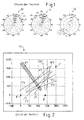
- a display 10 of a first search radar sensor A and a further display 11 of a second search radar sensor B and a third display 12 of a third search radar sensor C according to the prior art are shown.
- the display 10 shows distance (meters) and direction (degrees).
- Three destinations are displayed as A1 - A3.
- In the display 11 of the second search radar sensor B three targets are indicated as B1 - B3, and in the display 12 of the third search radar sensor C, three targets are displayed as C1 - C3.
- the measurements are placed in the geometry 13 of the parent Cartesian coordinate system.
- the position of the respective sensor A, B, C is required.
- Fig. 2 shows the known from the prior art representation of the measurement Fig. 1 in the parent system.
- A, B, C the radar positions are marked, in which the representation / geometries of the displays 10 to 12 result.
- the measurements are mapped here on a straight line, each pointing from the radar position A, B, C to the targets A1'-A3 ', B1'-B3' and C1'-C3 '.
- the straight line or track B1 ' shows the additional influence of the measurement error on the assignment according to the prior art.
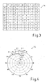
- Fig. 3 Visualized in an assignment matrix 14 that a clear assignment of a measurement is not possible in any case.
- Each measurement of A ' matches every measurement of B. Added to this is the possible assignment of C' to both sensors A ', B'.
- a space curve A1 is calculated in the local sensor coordinate system of the sensor A and now according to the novel method in Fig. 4 converted into the display 15 so in the local geometry of the radar B.
- all measurements that are relevant for the assignment to A1 are registered.
- all measurements of B (B1, B2, B3) are assignment candidates to A1.
- An unambiguous assignment is therefore not possible, so that all measurements of B are to be considered below, with only measurements along the curve A1 coming into question for an assignment. Measurements outside the range and azimuth range concerned, which is described by curve A1, need not be compared.
- the space curve A1 thus limits the search range for assignment candidates and thus reduces the number of comparisons.
- the space curves A1 and B1 - B3 of the associated measurements of the sensors A, B are projected in a further step in the geometry 16 of the sensor C.
- the ambiguities are solved.
- the procedure also simplifies the assignment for A2 and A3, which can be determined analogously.
- the already assigned measurements C3 and B1 are no longer considered for this subsequent assignment.
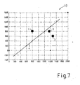
- intersection of the space curves brings another advantage. Since the 3D position is known from each point of the space curve, the corresponding elevation can be read directly at the point of contact of the local measurement with the curve. Thus, the location of the target in the parent coordinate system is determined.
- the aerial image (geometry 17 ( ⁇ geometry 13) of the superordinate Cartesian coordinate system) thus contains four targets, of which three from at least two of the sensors are observed simultaneously and thus a 3D position can be calculated.
- Target 1 and Target 2 are observed by all sensors A, B, C, while Target 3 can only be seen from A and B.
- Goal 4 is not measured by A and B, which is why its existence was first revealed by the correct assignment of the measurement.
Landscapes
- Engineering & Computer Science (AREA)
- Radar, Positioning & Navigation (AREA)
- Remote Sensing (AREA)
- Computer Networks & Wireless Communication (AREA)
- Physics & Mathematics (AREA)
- General Physics & Mathematics (AREA)
- Radar Systems Or Details Thereof (AREA)
- Respiratory Apparatuses And Protective Means (AREA)
- Traffic Control Systems (AREA)
- Sorption Type Refrigeration Machines (AREA)
Description
- Die Erfindung betrifft ein Verfahren zur Zuordnung von 2D Messungen eines Sensorverbundes, insbesondere für die Flugabwehr.
- Aus der
EP 0 205 794 A1 ist ein derartiges Rundsuchsystem zur Raum-/ Luftraumüberwachung bekannt. Die von einem IR- Ortungsgerät bei jedem Suchzyklus als Videosignale anfallenden Echtziele werden in einer Daten- Aufbereitungseinrichtung aufbereitet und in einem IR- Signalprozessor entsprechend ihren Elevationswerten und Azimutwerten diskriminiert und gespeichert. Die von den Geräten ermittelten Echtziel- Koordinaten in Elevation und Azimut und Distanz werden einer übergeordneten Feuerleiteinrichtung zugeführt. - Eine Funkmesseinrichtung zur Luftraumüberwachung ist der
DE 1 057 788 entnehmbar. Ein 2D -Puls-Dopplerradar wird in derDE 36 88 935 T2 beschrieben. DieDE 39 26 216 A1 offenbart ein Multifunktionsradar. Ein Sekundär- Radarsystem wird in derDE 41 09 981 A1 publiziert. - Bereits mit der
DE -PS 977 646 - Die
DE 198 56 231 A1 legt ein Verfahren zur Überwachung von Flugzeugen offen, welches unter Nutzung von Satelliten abläuft. Mit einem Verfahren zur Raumüberwachung befasst sich auch dieDE 100 32 433 A1 . Ein Versuch der Positionsbestimmung eines Flugzeuges in einem Dreiweg- DME- System zeigt dieDE 36 37 129 C2 auf.US 6 338 011 offenbart ein Verfahren zur Optimierung der Ziel- bestimmung gemäß dem Oberbegriff des Anspruchs 1. - Durch die Vernetzung der Sensoren als auch der Feuerleitgeräte können diese ihre aktuellen Zielzustandsmessungen (Ort und Geschwindigkeit) untereinander austauschen bzw. die Messungen an einen vorzugsweise zentralen Rechner senden. Zur Erstellung der augenblicklichen Luftlage werden die empfangenen Signale der jeweiligen Feuerleitgeräte dahingehend untersucht, ob sie vom selben oder von unterschiedlichen Zielen stammen. Nach erfolgter Zuordnung der in einem Zeitintervall eingegangenen Messungen wird eine Aussage darüber getroffen, wie viele Ziele in einem Luftraum aufgezeichnet werden, welche und wie viele davon neu sind und welche sowie wie viele bekannte Ziele einen aufdatierten Zustand besitzen. Insbesondere die Zuordnung von räumlich eng zusammen fliegenden Zielen ist mit bekannten Verfahren schwierig. Messfehler von Ort und Geschwindigkeit eines Zieles sind eine wesentliche Störquelle für eine korrekte Zuordnung. Die Fehler entstehen in der Regel beim Messvorgang oder bei einem notwendigen Zeitabgleich, was mittels Extrapolation zu einem gemeinsamen Zeitpunkt zum Vergleich mit anderen Messungen geschieht. Messfehler erhöhen die Wahrscheinlichkeit von Fehlzuordnungen. Der weitere Aspekt für Fehler liegt wie bereits erwähnt in der räumlichen Auflösung der bekannten 2D, 2.5D Sensoren, die eine der drei räumlichen Dimensionen gar nicht oder nur ungenügend auflösen können. So wird beispielsweise bei einem 2D Suchradar nur die Entfernung und Azimut eines Ziels bezüglich des Sensors gemessen, über die Elevation liegt hingegen keine Information vor. Bei 2.5D Suchradaren wird der Elevationsbereich des Ziels auf ein Intervall eingeschränkt. Passive elektro- optische Sensoren liefern hingegen Messungen von Azimut und Elevation, jedoch kann die Entfernung des Ziels nicht gemessen werden.
- Um die Messungen vergleichen zu können, müssen diese in ein gemeinsames, übergeordnetes Koordinatensystem konvertiert werden. Die Transformation einer lokalen 2D Messung ist nur durch eine Annahme der dritten Dimension in ein anderes dreidimensionales Koordinatensystem möglich. Diese verursacht ein weiteres Anwachsen der Messungenauigkeit bedingt durch eine große Messunsicherheit. Derartige Messungen sind im Allgemeinen schwer unterscheidbar, weshalb sich die Zuordnung erschwert.
- Zu den technischen Problemen in Genauigkeit und Auflösung kommt der Zeitaufwand für die Zuordnung hinzu. Bei großen vernetzten Luftabwehrverbänden, die einen zielintensiven Luftraum überwachen, führt die Zuordnung zu einem Rechen- und Zeitaufwand, der nur eine sehr geringe Aufdatierung erlaubt.
- Ein Verfahren zur automatischen kombinatorischen Optimierung von Zuordnungen bei der Bahnverfolgung mehrerer sich bewegender Objekte schlägt die
DE 44 39 742 C2 vor. Ausgehend von einer mehr oder weniger zufällig gewählten, beliebigen, jedoch gültigen Zuordnungsmatrix wird eine neue Zuordnungsmatrix generiert. Danach wird überprüft, ob diese eine bessere Lösung darstellt als die alte Zuordnungsmatrix. Ist dies der Fall, wird diese Matrix als neuer Ausgangspunkt für eine weitere Suche beibehalten. Durch dieses Verfahren soll eine zeitaufwendige Suche vermieden, eine ausreichende Güte erreicht werden. - Hier stellt sich die Erfindung die Aufgabe, ein Verfahren anzugeben, mit dem eine ausreichend genaue Zuordnung der Ziele bei minimiertem Zeitaufwand vorgenommen werden kann.
- Gelöst wird die Aufgabe durch die Merkmale des Patentanspruchs 1.
- Der Erfindung liegt die Idee zugrunde, die bekannte Geometrie der Messungen auszunutzen, um sie einander zuzuordnen und um Mehrdeutigkeiten zu lösen, wobei gleichzeitig durch einen räumlichen Schnitt die 3D Position eines Zieles im Raum bestimmt wird.
- Für das Wirksamsein des Verfahrens wird vorausgesetzt, dass Translation, Rotation und Skalierung eines jeden Sensors bezüglich eines gemeinsamen Koordinatensystems, in dem sich alle Sensoren eines Verbandes befinden, bekannt sind. Diese Voraussetzung ist zumindest dann als erfüllt ansehbar, wenn ein Luftraumüberwachungssensor eingerichtet worden ist, insbesondere die Nordausrichtung bestimmt und er horizontiert ist, und seine Position beispielsweise mittels GPS bestimmt wurde.
- Das Verfahren basiert auf dem Effekt, dass die fehlende Dimension als Messintervall interpretiert werden kann, so dass eine zweidimensionale Messung im übergeordneten System eine 3D Raumkurve entlang der fehlenden Dimension beschreibt. Das Ziel liegt zum Zeitpunkt der Messung auf dieser Kurve, seine 3D Position ist unbekannt. Wenn ein Ziel von zwei 2D Sensoren beobachtet wird, dann schneiden sich die Raumkurven im messfehterfreien Fall am Ort des Ziels. Diese Tatsache aufgreifend löst das Verfahren nunmehr das Zuordnungsproblem durch Projektion der Meldung eines Feuerleitgerätes in die lokale Geometrie der Sensoren der übrigen Feuerleitgeräte.
- Das Verfahren umfasst N -1 Schritte pro Messung, wobei N die Anzahl der Sensoren ist. In einem ersten Schritt wird eine Art Mastersensor bestimmt und seine Raumkurve berechnet. Anschließend wird die Kurve in die Geometrie eines anderen, als Slave- Sensor bestimmten Sensors übertragen. Es werden danach die Raumkurven der im vorhergehenden Schritt gewonnenen Korrespondenz berechnet und zusammen mit der Master Kurve in die Geometrie des nächsten, als neuen Slave- Sensor definierten Sensors übertragen. Können durch die neue Information Mehrdeutigkeiten aus dem ersten Schritt gelöst werden, werden die betreffenden Messungen aus der Zuordnungsliste gelöscht. Alle neu hinzukommenden Partner zur Master Messung werden wieder aufgezeichnet. Im letzten Schritt wird der letzte verbleibende Sensor als Slave definiert. Der Master und alle ihm zugeordneten Messungen der bisherigen Slave- Sensoren werden in die lokale Geometrie übertragen und mit den Messungen verglichen. Nach der Zuordnung der lokalen Messung wird überprüft, ob zum Master nur jeweils maximal eine Messung der Slave- Sensoren zugeordnet ist. Ist dies nicht der Fall, wird die Mehrdeutigkeit zu diesem Zeitpunkt mit dem kleinsten Abstand der jeweiligen Messung zum Sensor gelöst. Damit ist die Zuordnung zum Master abgeschlossen. Sämtliche zugeordnete Messungen werden abgespeichert und brauchen für die weitere Betrachtung nicht mehr berücksichtigt zu werden.
- Das gleiche Verfahren wird nun solange auf den ersten Master- Sensor angewendet, bis alle Messungen zugeordnet wurden. Anschließend wird ein bisheriger Slave- Sensor zum neuen Master bestimmt und das Verfahren auf die verbleibenden Ziele angewendet.
- Die Vorteile dieses Verfahrens lassen sich wie folgt beschreiben. Das Verfahren ermöglicht eine eindeutige Zuordnung von 2D sowie 2.50 Messungen eines Sensorverbundes, wobei alle physikalisch möglichen Zustände verglichen werden, fehlerhafte Annahmen bezüglich der Ziellage entfallen. Jede Messung wird maximal einer Messung eines anderen Sensors zugeordnet, die zudem auf geometrischen Bedingungen beruht und somit die Abhängigkeit der Entscheidung von Abstandsrechnungen reduziert. Die Zuordnung erfolgt des Weiteren individuell für jede Messung, so dass es nicht mehr nötig ist, alle möglichen Korrespondenzen auszurechnen, da Vergleiche mit bereits zugeordneten Messungen entfallen. Dadurch werden der Rechenaufwand sowie die benötigte Zeit verringert. Die Komplexität des Verfahrens ist linear und eignet sich speziell bei Szenarien mit vielen Sensoren und Zielen. Das Verfahren schließt alle möglichen Sensortypen ein, sowohl Suchradare als auch elektrooptische Sensoren oder IR- Sensoren. Je mehr Sensoren Messungen liefern desto verlässlicher und eindeutiger wird das Ergebnis durch die Zunahme räumlicher Informationen. Durch den Raumschnitt wird die 3D Position des Zieles schon während der Zuordnung erkannt / bekannt.
- Anhand eines Ausführungsbeispiels mit Zeichnung und ausgehend vom Stand der Technik soll die Erfindung näher erläutert werden.
- Es zeigt
- Fig. 1
- eine Darstellung der Messungen auf der Anzeige von drei 2D Suchradar Sensoren eines vernetzten Luftabwehrverbandes nach dem Stand der Technik,
- Fig. 2
- eine Darstellung der Anzeigen aus
Fig. 1 in der X-Y Ebene des übergeordneten Systems nach dem Stand der Technik, - Fig. 3
- eine Darstellung der Zuordnungsmatrix als Resultat aus
Fig. 2 , - Fig. 4
- eine Projektion einer Raumkurve des ersten Suchradars in die lokale Geometrie des zweiten Suchradars,
- Fig. 5
- eine Projektion der Raumkurve des zweiten Suchradars in die lokale Geometrie des dritten Sensors,
- Fig. 6
- eine Projektion der Raumkurve des ersten Suchradars in die Projektion nach
Fig. 5 , - Fig. 7
- eine aus den Zuordnungen bestimmte Zielposition in der X-Y Ebene des übergeordneten Koordinatensystems.
- In
Fig. 1 ist eine Anzeige 10 eines ersten Suchradar Sensors A sowie eine weitere Anzeige 11 eines zweiten Suchradar Sensors B und eine dritte Anzeige 12 eines dritten Suchradar Sensors C nach dem Stand der Technik dargestellt. In der Anzeige 10 sind Entfernung (Meter) und Richtung (Grad) angegeben. Es werden drei Ziele als A1 - A3 angezeigt. In der Anzeige 11 des zweiten Suchradar Sensors B werden drei Ziele als B1 - B3 und in der Anzeige 12 des dritten Suchradar Sensors C werden drei Ziele als C1 - C3 angezeigt. - Zur Korrelation werden die Messungen in die Geometrie 13 des übergeordneten kartesischen Koordinatensystems gebracht. Hierzu wird die Position des jeweiligen Sensors A, B, C benötigt.
-
Fig. 2 zeigt die nach dem Stand der Technik bekannte Darstellung der Messung ausFig. 1 im übergeordneten System. Mit A, B, C sind die Radar Positionen gekennzeichnet, in denen sich die Darstellung / Geometrien der Anzeigen 10 bis 12 ergeben. Die Messungen werden hier auf einer Geraden abgebildet, die jeweils von der Radar Position A, B, C zu den Zielen A1'- A3', B1'- B3' sowie C1'-C3' weisen. Insbesondere die Gerade bzw. Spur B1' zeigt den zusätzlichen Einfluss des Messfehlers auf die Zuordnung nach dem Stand der Technik.Fig. 3 visualisiert in einer Zuordnungsmatrix 14, dass eine eindeutige Zuordnung einer Messung in keinem Fall möglich ist. Jede Messung von A' passt zu jeder Messung von B. Hinzu kommt noch die mögliche Zuordnung von C' zu beiden Sensoren A', B'. - Basierend auf die Anzeigen 10 bis 12 aus der
Fig. 1 wird daher im lokalen Sensorkoordinatensystem des Sensors A eine Raumkurve A1 berechnet und nunmehr nach dem neuartigen Verfahren inFig. 4 in die Anzeige 15 also in die lokale Geometrie des Radars B konvertiert. Hier werden alle für die Zuordnung zu A1 in Frage kommenden Messungen registriert. Im Beispiel sind alle Messungen von B (B1, B2, B3) Zuordnungskandidaten zu A1. Eine eindeutige Zuordnung ist daher nicht möglich, so dass alle Messungen von B im Weiteren zu betrachten sind, wobei nur Messungen entlang der Kurve A1 für eine Zuordnung in Frage kommen. Messungen außerhalb des betreffenden Entfernungs- und Azimut- Bereichs, den die Kurve A1 beschreibt, brauchen nicht verglichen werden. Die Raumkurve A1 schränkt somit den Suchbereich für Zuordnungskandidaten ein und reduziert somit die Anzahl der Vergleiche. - Zur Lösung der Mehrdeutigkeit werden die Raumkurven A1 und B1 - B3 von den zugeordneten Messungen der Sensoren A, B in einem weiteren Schritt in die Geometrie 16 des Sensors C projiziert. Hier werden nun die Mehrdeutigkeiten gelöst.
- Im Beispiel nach
Fig. 4 entstehen bei der Projektion der Raumkurven B1 - B3 in die Geometrie von C weitere Mehrdeutigkeiten. B1 kann sowohl zu C2 als auch C3 zugeordnet werden. B3 lässt sich keiner Messung von C zuordnen. Das Paar B2 - C1 weist jedoch eine eindeutige Zuordnung auf. Die neuen Mehrdeutigkeiten werden nun durch das Projizieren der Raumkurve A1 in die lokale Geometrie von C (Fig. 6 ) übertragen. A1 schneidet sich mit B1 bei der Messung C3. Diese drei Werte werden einander zugeordnet. Gleichzeitig löst sich damit sowohl das Mehrdeutigkeitsproblem von A1 mit B1- B3 als auch das von B1 mit C2 und C3. - Das Verfahren vereinfacht auch die Zuordnung für A2 und A3, die sich analog bestimmen lassen. Die bereits zugeordneten Messungen C3 und B1 werden für diese nachfolgende Zuordnung nicht mehr betrachtet.
- Die Verschneidung der Raumkurven bringt einen weiteren Vorteil mit sich. Da von jedem Punkt der Raumkurve die 3D Lage bekannt ist, lässt sich im Berührungspunkt der lokalen Messung mit der Kurve die zugehörige Elevation direkt ablesen. Somit ist die Lage des Ziels im übergeordneten Koordinatensystem bestimmt.
- Als Lösung für das beschriebene Beispiel ergeben sich folgende, in
Fig. 7 dargestellte Zuordnungen. - Ziel 1: A1 - B1 -C3
- Ziel 2: A2 - B2 -C1
- Ziel 3: A3 - B3
- Ziel 4: C2.
- Das Luftbild (Geometrie 17 (^ Geometrie 13) des übergeordneten kartesischen Koordinatensystems) enthält also vier Ziele, wovon drei von mindestens zwei der Sensoren gleichzeitig beobachtet werden und somit eine 3D Position berechenbar ist. Ziel 1 und Ziel 2 werden von allen Sensoren A, B, C beobachtet, während das Ziel 3 nur von A und B gesehen werden kann. Ziel 4 wird nicht von A und B gemessen, weshalb seine Existenz erst durch die korrekte Zuordnung der Messung enthüllt wurde.
Claims (7)
- Verfahren zur automatischen kombinatorischen Optimierung der Zielbestimmung mehrerer sich bewegender Objekte (1, 2, 3) unter zur Hilfenahme von mehreren (N) Sensoren (A, B, C) und deren Geometrien (10, 11, 12), dadurch gekennzeichnet, dass ein erster Sensor (A) zum Mastersensor bestimmt und eine Raumkurve (A1) berechnet wird, die anschließend in die Geometrie (11) eines als Slave- Sensor bestimmten Sensors (B) übertragen und in seiner lokalen Geometrie (15) berücksichtigt wird, danach wird ein weiterer Sensor (C) als Slave definiert, in den die Raumkurven (B1 - B3) der im vorhergehenden Schritt gewonnenen Korrespondenz berechnet und zusammen mit der Master Kurve (A1) in die Geometrie (12) des neuen Slave- Sensors (C) übertragen und als neue Geometrie (16) berücksichtigt werden, wobei diese Schritte zumindest solange wiederholt werden, bis in einem letzten Schritt (N-1) der letzte (N) verbleibende Sensor als Slave definiert wird, der Master (A1) und alle ihm zugeordneten Messungen der bisherigen Slave- Sensoren (B, C... N-1) in die lokale Geometrie des letzten (N) Slave- Sensors übertragen und mit den Messungen verglichen werden.
- Verfahren nach Anspruch 1, dadurch gekennzeichnet, dass wenn neue Informationen Mehrdeutigkeiten aus dem vorherigen Schritt lösen, die betreffenden Messungen aus einer Zuordnungsliste (14) gelöscht, jedoch alle neu hinzukommenden aufgezeichnet werden.
- Verfahren nach Anspruch 1 oder 2, dadurch gekennzeichnet, dass nach der Zuordnung der lokalen Messung überprüft wird, ob zum Master (A) nur jeweils maximal eine Messung der Slave Sensoren (B, C) zugeordnet ist, wobei dann, wenn dies nicht der Fall ist, die Mehrdeutigkeit zu diesem Zeitpunkt mit dem kleinsten Abstand der jeweiligen Messung zum Sensor (B, C) gelöst wird, wodurch die Zuordnung zum Master (A) abgeschlossen ist.
- Verfahren nach Anspruch 1, dadurch gekennzeichnet, dass das nach erfolgter Zuordnung des ersten Master- Sensors (A) ein nächster Slave- Sensor (B) zum Master bestimmt und die Schritte auf die verbleibenden Ziele wiederholt werden.
- Verfahren nach Anspruch 1, dadurch gekennzeichnet, dass zur Korrelation die Messungen des Masters in die Geometrie (16) des jeweiligen Slave- Sensors gebracht werden.
- Verfahren nach einem der vorgenannten Ansprüche, dadurch gekennzeichnet, dass mittels der Verschneidung der Raumkurven (A1, B1-B3, C1-C3) von jedem Punkt der Raumkurve (A1, B1-B3, C1-C3) die 3D Lage bekannt ist, wodurch sich im Berührungspunkt der lokalen Messung mit der Kurve (A1, B1-B3, C1-C3) die fehlende Dimension (Elevation / Distanz) direkt ablesen lässt.
- Verfahren nach den Ansprüchen 1 und 5, dadurch gekennzeichnet, dass die Komplexität der Zuordnung, und somit der dadurch verursachte Rechenaufwand, dadurch reduziert wird, dass die Anzahl der Korrelationen sich auf die Kandidaten entlang der Raumkurven, die in die Geometrie des jeweiligen Slave- Sensors projeziert worden sind, beschränkt.
Priority Applications (1)
| Application Number | Priority Date | Filing Date | Title |
|---|---|---|---|
| PL06762719T PL1920267T3 (pl) | 2005-09-02 | 2006-07-20 | Sposób nadzorowania przestrzeni powietrznej |
Applications Claiming Priority (2)
| Application Number | Priority Date | Filing Date | Title |
|---|---|---|---|
| DE102005041705A DE102005041705A1 (de) | 2005-09-02 | 2005-09-02 | Verfahren zur Raum-/Luftraumüberwachung |
| PCT/EP2006/007127 WO2007028454A1 (de) | 2005-09-02 | 2006-07-20 | Verfahren zur raum- / luftraumüberwachung |
Publications (2)
| Publication Number | Publication Date |
|---|---|
| EP1920267A1 EP1920267A1 (de) | 2008-05-14 |
| EP1920267B1 true EP1920267B1 (de) | 2009-09-16 |
Family
ID=37192329
Family Applications (1)
| Application Number | Title | Priority Date | Filing Date |
|---|---|---|---|
| EP06762719A Not-in-force EP1920267B1 (de) | 2005-09-02 | 2006-07-20 | Verfahren zur raum- / luftraumüberwachung |
Country Status (11)
| Country | Link |
|---|---|
| US (1) | US8044840B2 (de) |
| EP (1) | EP1920267B1 (de) |
| AT (1) | ATE443272T1 (de) |
| CA (1) | CA2620357A1 (de) |
| DE (2) | DE102005041705A1 (de) |
| ES (1) | ES2330470T3 (de) |
| NO (1) | NO20080108L (de) |
| PL (1) | PL1920267T3 (de) |
| PT (1) | PT1920267E (de) |
| WO (1) | WO2007028454A1 (de) |
| ZA (1) | ZA200800613B (de) |
Families Citing this family (5)
| Publication number | Priority date | Publication date | Assignee | Title |
|---|---|---|---|---|
| DE102008023520C5 (de) * | 2008-05-15 | 2016-12-29 | Airbus Defence and Space GmbH | Verfahren zur Klassifikation von RAM-Geschossen |
| DE102009010362A1 (de) | 2009-02-25 | 2011-01-13 | Rheinmetall Waffe Munition Gmbh | Feuerleitung einer richtbaren Waffenanlage |
| IT1401374B1 (it) * | 2010-08-09 | 2013-07-18 | Selex Sistemi Integrati Spa | Tracciamento tridimensionale multisensore basato su tracce bidimensionali acquisite da tracciatori di sensori di localizzazione di bersagli |
| CH708274A1 (de) | 2013-07-04 | 2015-01-15 | Schweizerische Eidgenossenschaft Eidgenössisches Dept Für Verteidigung Bevölkerungsschutz Und Sport | Verfahren zur Bestimmung von Trajektorien beweglicher physischer Objekte in einem Raum, auf der Basis von Sensordaten mehrerer Sensoren. |
| JP7168493B2 (ja) * | 2018-03-23 | 2022-11-09 | 株式会社Soken | レーダ装置 |
Family Cites Families (14)
| Publication number | Priority date | Publication date | Assignee | Title |
|---|---|---|---|---|
| DE1057788B (de) | 1954-06-03 | 1959-05-21 | Telefunken Gmbh | Funkmesseinrichtung zur Luftraumueberwachung |
| NL262106A (de) | 1960-03-08 | |||
| DE3673699D1 (de) | 1985-05-23 | 1990-10-04 | Contraves Ag | Rundsuchsystem zur raum-/luftraumueberwachung. |
| IT1189972B (it) | 1986-02-21 | 1988-02-10 | Contraves Italiana Spa | Radar 2d a effetto doppler a impulsi |
| DE3637129A1 (de) | 1986-10-31 | 1988-05-11 | Deutsche Forsch Luft Raumfahrt | Verfahren zur positionsbestimmung eines flugzeuges in einem dreiweg-dme-system |
| DE3926216A1 (de) | 1989-08-08 | 1991-02-14 | Siemens Ag | Multifunktionsradar |
| DE4109981A1 (de) | 1991-03-27 | 1992-10-01 | Standard Elektrik Lorenz Ag | Sekundaer-radarsystem |
| US5448243A (en) * | 1991-12-30 | 1995-09-05 | Deutsche Forschungsanstalt Fur Luft- Und Raumfahrt E.V. | System for locating a plurality of objects and obstructions and for detecting and determining the rolling status of moving objects, such as aircraft, ground vehicles, and the like |
| DE4439742C1 (de) * | 1994-10-28 | 1996-03-07 | Daimler Benz Ag | Verfahren zur automatischen kombinatorischen Optimierung von Zuordnungen bei der Bahnverfolgung mehrerer sich bewegender Objekte |
| US6002358A (en) * | 1998-08-18 | 1999-12-14 | Northrop Grumman Corporation | Method and apparatus for determining whether two radar tracks represent the same physical object |
| DE19856231A1 (de) | 1998-12-04 | 2000-06-21 | Daimler Chrysler Ag | Satellitenkonstellation sowie System und Verfahren zur Überwachung von Flugzeugen |
| US6338011B1 (en) * | 2000-01-11 | 2002-01-08 | Solipsys Corporation | Method and apparatus for sharing vehicle telemetry data among a plurality of users over a communications network |
| DE10032433A1 (de) | 2000-07-04 | 2002-01-17 | H A N D Gmbh | Verfahren zur Bodenraumüberwachung |
| EP1464988B1 (de) * | 2003-04-03 | 2008-06-11 | Mitsubishi Electric Information Technology Centre Europe B.V. | Laufzeitdifferenzbestimmung in verteilten Sensornetzwerken |
-
2005
- 2005-09-02 DE DE102005041705A patent/DE102005041705A1/de not_active Withdrawn
-
2006
- 2006-07-20 AT AT06762719T patent/ATE443272T1/de active
- 2006-07-20 DE DE502006004884T patent/DE502006004884D1/de active Active
- 2006-07-20 US US11/991,288 patent/US8044840B2/en not_active Expired - Fee Related
- 2006-07-20 WO PCT/EP2006/007127 patent/WO2007028454A1/de not_active Ceased
- 2006-07-20 EP EP06762719A patent/EP1920267B1/de not_active Not-in-force
- 2006-07-20 ES ES06762719T patent/ES2330470T3/es active Active
- 2006-07-20 CA CA002620357A patent/CA2620357A1/en not_active Abandoned
- 2006-07-20 PL PL06762719T patent/PL1920267T3/pl unknown
- 2006-07-20 PT PT06762719T patent/PT1920267E/pt unknown
-
2008
- 2008-01-08 NO NO20080108A patent/NO20080108L/no not_active Application Discontinuation
- 2008-01-21 ZA ZA200800613A patent/ZA200800613B/xx unknown
Also Published As
| Publication number | Publication date |
|---|---|
| CA2620357A1 (en) | 2007-03-15 |
| ATE443272T1 (de) | 2009-10-15 |
| US8044840B2 (en) | 2011-10-25 |
| ES2330470T3 (es) | 2009-12-10 |
| ZA200800613B (en) | 2009-02-25 |
| US20100007544A1 (en) | 2010-01-14 |
| DE102005041705A1 (de) | 2007-03-15 |
| PT1920267E (pt) | 2009-10-26 |
| NO20080108L (no) | 2008-04-02 |
| DE502006004884D1 (de) | 2009-10-29 |
| PL1920267T3 (pl) | 2010-02-26 |
| WO2007028454A1 (de) | 2007-03-15 |
| EP1920267A1 (de) | 2008-05-14 |
Similar Documents
| Publication | Publication Date | Title |
|---|---|---|
| DE10143561B4 (de) | Verfahren und System zur Lokalisierung von Emittern | |
| EP2601760B1 (de) | Verfahren, vorrichtung und system zur adressierung von betriebsgeräten für leuchtmittel | |
| EP3017319B1 (de) | Verfahren zur bestimmung von trajektorien beweglicher physischer objekte in einem raum, auf der basis von sensordaten mehrerer sensoren | |
| EP3060942B1 (de) | Verfahren zur bestimmung einer anordnung zumindest zweier sensoren und sensornetzwerk | |
| DE102022104880B4 (de) | Verfahren zur Kalibrierung eines portablen Referenzsensorsystems, portables Referenzsensorsystem und Verwendung des portablen Referenzsensorsystems | |
| EP3358363B1 (de) | Verfahren und system zur positionsbestimmung von mindestens einem flurförderzeug | |
| EP3722910A1 (de) | Verfahren zur optimierten simultanen lokalisierung und kartierung eines mobilen roboters | |
| WO2022228738A1 (de) | Orientierungsbasierte positionsermittlung von schienenfahrzeugen | |
| DE3835992A1 (de) | Kollisionsverhinderungssystem | |
| DE102018104056B3 (de) | Verfahren zur optimierten Anordnung und Ausrichtung eines Feldgerätes | |
| DE102017111860A1 (de) | Verfahren zum Kalibrieren eines Radarsensors eines Kraftfahrzeugs während einer Bewegung des Kraftfahrzeugs, Radarsensor, Fahrerassistenzsystem sowie Kraftfahrzeug | |
| DE102018220782A1 (de) | Lokalisierung eines Fahrzeugs anhand von dynamischen Objekten | |
| WO2008022622A1 (de) | Vorrichtung und verfahren zur positions- und/oder geschwindigkeitsbestimmung, insbesondere unter einsatz von absolutlaufzeiten und laufzeitunterschieden von signalen | |
| WO2007028454A1 (de) | Verfahren zur raum- / luftraumüberwachung | |
| EP1153314B1 (de) | Verfahren und vorrichtung zur positionsbestimmung | |
| DE102007037178A1 (de) | Verfahren und System zur Bewertung mindestens eines Umfeldsensors eines Fahrzeugs zum Erkennen mindestens eines Objekts | |
| DE3930109C1 (de) | ||
| DE102010052475B4 (de) | Ortungssystem | |
| DE102010023960A1 (de) | Verfahren und Vorrichtung zur Ortsbestimmung | |
| DE102018210079A1 (de) | Verfahren zum initialen Kalibrieren eines Sensors für ein Fahrerassistenzsystem eines Fahrzeugs | |
| EP1965222A2 (de) | Verfahren und Vorrichtung zur Verfolgung mindestens eines sich bewegenden Objekts | |
| DE102013021841A1 (de) | Verfahren zum Zuordnen einer Betriebsinformation eines Fremd-Kraftfahrzeugs | |
| DE102017010308A1 (de) | Verfahren zur Raumausmessung und Raummessanordnung | |
| DE3938340A1 (de) | Verfahren und einrichtung zur funkortung durch ueberwachungs-sekundaerradar | |
| EP3078934A1 (de) | Vermessungssystem und vermessungsverfahren |
Legal Events
| Date | Code | Title | Description |
|---|---|---|---|
| PUAI | Public reference made under article 153(3) epc to a published international application that has entered the european phase |
Free format text: ORIGINAL CODE: 0009012 |
|
| 17P | Request for examination filed |
Effective date: 20080215 |
|
| AK | Designated contracting states |
Kind code of ref document: A1 Designated state(s): AT BE BG CH CY CZ DE DK EE ES FI FR GB GR HU IE IS IT LI LT LU LV MC NL PL PT RO SE SI SK TR |
|
| RAP1 | Party data changed (applicant data changed or rights of an application transferred) |
Owner name: RHEINMETALL AIR DEFENCE AG |
|
| GRAP | Despatch of communication of intention to grant a patent |
Free format text: ORIGINAL CODE: EPIDOSNIGR1 |
|
| GRAS | Grant fee paid |
Free format text: ORIGINAL CODE: EPIDOSNIGR3 |
|
| GRAA | (expected) grant |
Free format text: ORIGINAL CODE: 0009210 |
|
| AK | Designated contracting states |
Kind code of ref document: B1 Designated state(s): AT BE BG CH CY CZ DE DK EE ES FI FR GB GR HU IE IS IT LI LT LU LV MC NL PL PT RO SE SI SK TR |
|
| REG | Reference to a national code |
Ref country code: GB Ref legal event code: FG4D Free format text: NOT ENGLISH |
|
| REG | Reference to a national code |
Ref country code: CH Ref legal event code: EP |
|
| REG | Reference to a national code |
Ref country code: IE Ref legal event code: FG4D |
|
| REG | Reference to a national code |
Ref country code: PT Ref legal event code: SC4A Free format text: AVAILABILITY OF NATIONAL TRANSLATION Effective date: 20091020 |
|
| REF | Corresponds to: |
Ref document number: 502006004884 Country of ref document: DE Date of ref document: 20091029 Kind code of ref document: P |
|
| REG | Reference to a national code |
Ref country code: RO Ref legal event code: EPE |
|
| REG | Reference to a national code |
Ref country code: SE Ref legal event code: TRGR |
|
| REG | Reference to a national code |
Ref country code: ES Ref legal event code: FG2A Ref document number: 2330470 Country of ref document: ES Kind code of ref document: T3 |
|
| REG | Reference to a national code |
Ref country code: GR Ref legal event code: EP Ref document number: 20090402693 Country of ref document: GR |
|
| PG25 | Lapsed in a contracting state [announced via postgrant information from national office to epo] |
Ref country code: FI Free format text: LAPSE BECAUSE OF FAILURE TO SUBMIT A TRANSLATION OF THE DESCRIPTION OR TO PAY THE FEE WITHIN THE PRESCRIBED TIME-LIMIT Effective date: 20090916 Ref country code: LT Free format text: LAPSE BECAUSE OF FAILURE TO SUBMIT A TRANSLATION OF THE DESCRIPTION OR TO PAY THE FEE WITHIN THE PRESCRIBED TIME-LIMIT Effective date: 20090916 |
|
| LTIE | Lt: invalidation of european patent or patent extension |
Effective date: 20090916 |
|
| PG25 | Lapsed in a contracting state [announced via postgrant information from national office to epo] |
Ref country code: SI Free format text: LAPSE BECAUSE OF FAILURE TO SUBMIT A TRANSLATION OF THE DESCRIPTION OR TO PAY THE FEE WITHIN THE PRESCRIBED TIME-LIMIT Effective date: 20090916 Ref country code: LV Free format text: LAPSE BECAUSE OF FAILURE TO SUBMIT A TRANSLATION OF THE DESCRIPTION OR TO PAY THE FEE WITHIN THE PRESCRIBED TIME-LIMIT Effective date: 20090916 |
|
| REG | Reference to a national code |
Ref country code: PL Ref legal event code: T3 |
|
| REG | Reference to a national code |
Ref country code: HU Ref legal event code: AG4A Ref document number: E006681 Country of ref document: HU |
|
| PG25 | Lapsed in a contracting state [announced via postgrant information from national office to epo] |
Ref country code: CY Free format text: LAPSE BECAUSE OF FAILURE TO SUBMIT A TRANSLATION OF THE DESCRIPTION OR TO PAY THE FEE WITHIN THE PRESCRIBED TIME-LIMIT Effective date: 20090916 |
|
| REG | Reference to a national code |
Ref country code: IE Ref legal event code: FD4D |
|
| PG25 | Lapsed in a contracting state [announced via postgrant information from national office to epo] |
Ref country code: EE Free format text: LAPSE BECAUSE OF FAILURE TO SUBMIT A TRANSLATION OF THE DESCRIPTION OR TO PAY THE FEE WITHIN THE PRESCRIBED TIME-LIMIT Effective date: 20090916 Ref country code: IE Free format text: LAPSE BECAUSE OF FAILURE TO SUBMIT A TRANSLATION OF THE DESCRIPTION OR TO PAY THE FEE WITHIN THE PRESCRIBED TIME-LIMIT Effective date: 20090916 Ref country code: IS Free format text: LAPSE BECAUSE OF FAILURE TO SUBMIT A TRANSLATION OF THE DESCRIPTION OR TO PAY THE FEE WITHIN THE PRESCRIBED TIME-LIMIT Effective date: 20100116 |
|
| PG25 | Lapsed in a contracting state [announced via postgrant information from national office to epo] |
Ref country code: SK Free format text: LAPSE BECAUSE OF FAILURE TO SUBMIT A TRANSLATION OF THE DESCRIPTION OR TO PAY THE FEE WITHIN THE PRESCRIBED TIME-LIMIT Effective date: 20090916 |
|
| PLBE | No opposition filed within time limit |
Free format text: ORIGINAL CODE: 0009261 |
|
| STAA | Information on the status of an ep patent application or granted ep patent |
Free format text: STATUS: NO OPPOSITION FILED WITHIN TIME LIMIT |
|
| PG25 | Lapsed in a contracting state [announced via postgrant information from national office to epo] |
Ref country code: DK Free format text: LAPSE BECAUSE OF FAILURE TO SUBMIT A TRANSLATION OF THE DESCRIPTION OR TO PAY THE FEE WITHIN THE PRESCRIBED TIME-LIMIT Effective date: 20090916 |
|
| 26N | No opposition filed |
Effective date: 20100617 |
|
| PG25 | Lapsed in a contracting state [announced via postgrant information from national office to epo] |
Ref country code: MC Free format text: LAPSE BECAUSE OF NON-PAYMENT OF DUE FEES Effective date: 20100731 |
|
| PGFP | Annual fee paid to national office [announced via postgrant information from national office to epo] |
Ref country code: PT Payment date: 20110630 Year of fee payment: 6 |
|
| PGFP | Annual fee paid to national office [announced via postgrant information from national office to epo] |
Ref country code: CZ Payment date: 20110718 Year of fee payment: 6 Ref country code: AT Payment date: 20110714 Year of fee payment: 6 Ref country code: HU Payment date: 20110802 Year of fee payment: 6 Ref country code: GB Payment date: 20110721 Year of fee payment: 6 |
|
| PGFP | Annual fee paid to national office [announced via postgrant information from national office to epo] |
Ref country code: BE Payment date: 20110713 Year of fee payment: 6 |
|
| PG25 | Lapsed in a contracting state [announced via postgrant information from national office to epo] |
Ref country code: BG Free format text: LAPSE BECAUSE OF FAILURE TO SUBMIT A TRANSLATION OF THE DESCRIPTION OR TO PAY THE FEE WITHIN THE PRESCRIBED TIME-LIMIT Effective date: 20090916 Ref country code: LU Free format text: LAPSE BECAUSE OF NON-PAYMENT OF DUE FEES Effective date: 20100720 |
|
| REG | Reference to a national code |
Ref country code: PT Ref legal event code: MM4A Free format text: LAPSE DUE TO NON-PAYMENT OF FEES Effective date: 20130121 |
|
| BERE | Be: lapsed |
Owner name: RHEINMETALL AIR DEFENCE A.G. Effective date: 20120731 |
|
| REG | Reference to a national code |
Ref country code: AT Ref legal event code: MM01 Ref document number: 443272 Country of ref document: AT Kind code of ref document: T Effective date: 20120720 |
|
| GBPC | Gb: european patent ceased through non-payment of renewal fee |
Effective date: 20120720 |
|
| PG25 | Lapsed in a contracting state [announced via postgrant information from national office to epo] |
Ref country code: HU Free format text: LAPSE BECAUSE OF NON-PAYMENT OF DUE FEES Effective date: 20120721 Ref country code: GB Free format text: LAPSE BECAUSE OF NON-PAYMENT OF DUE FEES Effective date: 20120720 Ref country code: CZ Free format text: LAPSE BECAUSE OF NON-PAYMENT OF DUE FEES Effective date: 20120720 |
|
| PG25 | Lapsed in a contracting state [announced via postgrant information from national office to epo] |
Ref country code: PT Free format text: LAPSE BECAUSE OF NON-PAYMENT OF DUE FEES Effective date: 20130121 Ref country code: BE Free format text: LAPSE BECAUSE OF NON-PAYMENT OF DUE FEES Effective date: 20120731 |
|
| PG25 | Lapsed in a contracting state [announced via postgrant information from national office to epo] |
Ref country code: AT Free format text: LAPSE BECAUSE OF NON-PAYMENT OF DUE FEES Effective date: 20120720 |
|
| PGFP | Annual fee paid to national office [announced via postgrant information from national office to epo] |
Ref country code: PL Payment date: 20130624 Year of fee payment: 8 Ref country code: TR Payment date: 20130625 Year of fee payment: 8 Ref country code: RO Payment date: 20130626 Year of fee payment: 8 |
|
| PGFP | Annual fee paid to national office [announced via postgrant information from national office to epo] |
Ref country code: SE Payment date: 20130719 Year of fee payment: 8 Ref country code: ES Payment date: 20130729 Year of fee payment: 8 Ref country code: DE Payment date: 20130722 Year of fee payment: 8 Ref country code: NL Payment date: 20130719 Year of fee payment: 8 Ref country code: CH Payment date: 20130719 Year of fee payment: 8 Ref country code: GR Payment date: 20130729 Year of fee payment: 8 |
|
| PGFP | Annual fee paid to national office [announced via postgrant information from national office to epo] |
Ref country code: FR Payment date: 20130722 Year of fee payment: 8 |
|
| PGFP | Annual fee paid to national office [announced via postgrant information from national office to epo] |
Ref country code: IT Payment date: 20130723 Year of fee payment: 8 |
|
| REG | Reference to a national code |
Ref country code: DE Ref legal event code: R119 Ref document number: 502006004884 Country of ref document: DE |
|
| REG | Reference to a national code |
Ref country code: NL Ref legal event code: V1 Effective date: 20150201 |
|
| REG | Reference to a national code |
Ref country code: CH Ref legal event code: PL |
|
| REG | Reference to a national code |
Ref country code: SE Ref legal event code: EUG |
|
| PG25 | Lapsed in a contracting state [announced via postgrant information from national office to epo] |
Ref country code: NL Free format text: LAPSE BECAUSE OF NON-PAYMENT OF DUE FEES Effective date: 20150201 |
|
| REG | Reference to a national code |
Ref country code: GR Ref legal event code: ML Ref document number: 20090402693 Country of ref document: GR Effective date: 20150204 |
|
| REG | Reference to a national code |
Ref country code: FR Ref legal event code: ST Effective date: 20150331 |
|
| PG25 | Lapsed in a contracting state [announced via postgrant information from national office to epo] |
Ref country code: RO Free format text: LAPSE BECAUSE OF NON-PAYMENT OF DUE FEES Effective date: 20140720 Ref country code: CH Free format text: LAPSE BECAUSE OF NON-PAYMENT OF DUE FEES Effective date: 20140731 Ref country code: IT Free format text: LAPSE BECAUSE OF NON-PAYMENT OF DUE FEES Effective date: 20140720 Ref country code: DE Free format text: LAPSE BECAUSE OF NON-PAYMENT OF DUE FEES Effective date: 20150203 Ref country code: LI Free format text: LAPSE BECAUSE OF NON-PAYMENT OF DUE FEES Effective date: 20140731 |
|
| REG | Reference to a national code |
Ref country code: DE Ref legal event code: R119 Ref document number: 502006004884 Country of ref document: DE Effective date: 20150203 |
|
| PG25 | Lapsed in a contracting state [announced via postgrant information from national office to epo] |
Ref country code: SE Free format text: LAPSE BECAUSE OF NON-PAYMENT OF DUE FEES Effective date: 20140721 Ref country code: FR Free format text: LAPSE BECAUSE OF NON-PAYMENT OF DUE FEES Effective date: 20140731 Ref country code: GR Free format text: LAPSE BECAUSE OF NON-PAYMENT OF DUE FEES Effective date: 20150204 |
|
| REG | Reference to a national code |
Ref country code: ES Ref legal event code: FD2A Effective date: 20150826 |
|
| PG25 | Lapsed in a contracting state [announced via postgrant information from national office to epo] |
Ref country code: ES Free format text: LAPSE BECAUSE OF NON-PAYMENT OF DUE FEES Effective date: 20140721 |
|
| REG | Reference to a national code |
Ref country code: PL Ref legal event code: LAPE |
|
| PG25 | Lapsed in a contracting state [announced via postgrant information from national office to epo] |
Ref country code: PL Free format text: LAPSE BECAUSE OF NON-PAYMENT OF DUE FEES Effective date: 20140720 |
|
| PG25 | Lapsed in a contracting state [announced via postgrant information from national office to epo] |
Ref country code: TR Free format text: LAPSE BECAUSE OF NON-PAYMENT OF DUE FEES Effective date: 20140720 |