EP1920264B1 - Batteriesensoreinheit - Google Patents
Batteriesensoreinheit Download PDFInfo
- Publication number
- EP1920264B1 EP1920264B1 EP06777559A EP06777559A EP1920264B1 EP 1920264 B1 EP1920264 B1 EP 1920264B1 EP 06777559 A EP06777559 A EP 06777559A EP 06777559 A EP06777559 A EP 06777559A EP 1920264 B1 EP1920264 B1 EP 1920264B1
- Authority
- EP
- European Patent Office
- Prior art keywords
- battery
- sensor unit
- battery sensor
- measurement section
- fastening apparatus
- Prior art date
- Legal status (The legal status is an assumption and is not a legal conclusion. Google has not performed a legal analysis and makes no representation as to the accuracy of the status listed.)
- Not-in-force
Links
Images

Classifications
-
- G—PHYSICS
- G01—MEASURING; TESTING
- G01R—MEASURING ELECTRIC VARIABLES; MEASURING MAGNETIC VARIABLES
- G01R1/00—Details of instruments or arrangements of the types included in groups G01R5/00 - G01R13/00 and G01R31/00
- G01R1/20—Modifications of basic electric elements for use in electric measuring instruments; Structural combinations of such elements with such instruments
- G01R1/203—Resistors used for electric measuring, e.g. decade resistors standards, resistors for comparators, series resistors, shunts
-
- G—PHYSICS
- G01—MEASURING; TESTING
- G01R—MEASURING ELECTRIC VARIABLES; MEASURING MAGNETIC VARIABLES
- G01R31/00—Arrangements for testing electric properties; Arrangements for locating electric faults; Arrangements for electrical testing characterised by what is being tested not provided for elsewhere
- G01R31/36—Arrangements for testing, measuring or monitoring the electrical condition of accumulators or electric batteries, e.g. capacity or state of charge [SoC]
- G01R31/382—Arrangements for monitoring battery or accumulator variables, e.g. SoC
- G01R31/3835—Arrangements for monitoring battery or accumulator variables, e.g. SoC involving only voltage measurements
-
- G—PHYSICS
- G01—MEASURING; TESTING
- G01R—MEASURING ELECTRIC VARIABLES; MEASURING MAGNETIC VARIABLES
- G01R31/00—Arrangements for testing electric properties; Arrangements for locating electric faults; Arrangements for electrical testing characterised by what is being tested not provided for elsewhere
- G01R31/36—Arrangements for testing, measuring or monitoring the electrical condition of accumulators or electric batteries, e.g. capacity or state of charge [SoC]
- G01R31/364—Battery terminal connectors with integrated measuring arrangements
-
- Y—GENERAL TAGGING OF NEW TECHNOLOGICAL DEVELOPMENTS; GENERAL TAGGING OF CROSS-SECTIONAL TECHNOLOGIES SPANNING OVER SEVERAL SECTIONS OF THE IPC; TECHNICAL SUBJECTS COVERED BY FORMER USPC CROSS-REFERENCE ART COLLECTIONS [XRACs] AND DIGESTS
- Y10—TECHNICAL SUBJECTS COVERED BY FORMER USPC
- Y10T—TECHNICAL SUBJECTS COVERED BY FORMER US CLASSIFICATION
- Y10T29/00—Metal working
- Y10T29/49—Method of mechanical manufacture
- Y10T29/49826—Assembling or joining
Definitions
- the invention relates to a battery sensor unit with a fastening device and a measuring section and a method for connecting a fastening device of a battery sensor unit with a measuring section according to the preamble of the independent claims.
- the variables temperature, current and / or voltage are usually detected and processed by means of suitable algorithms. It is typically used in microcontroller or a corresponding computer unit. In general, shunts and inductive current sensors, such as compensation sensors, fluxgate or Hall elements, are used for current detection.
- a battery sensor device with a directly connectable to a pole of a motor vehicle battery fastening device is known, wherein the fastening device and a battery sensor are combined to form an integrated unit.
- the battery sensor device is adapted in shape and size to conventional Batteriepolwannen.
- the battery sensor consists of a planar measuring shunt and an electronic unit, wherein the measuring shunt is designed as a resistance element with two designed as a mechanical support resistor terminals.
- the battery sensor unit according to the invention with a fastening device for attaching the battery sensor unit to a contact of a battery, in particular a motor vehicle battery, and with a measuring path for detecting the state of the battery, the measuring section and the fastening device to an integral Assembled unit, the advantage that no significant, constructive modifications are necessary for a change in the cable outlet direction.
- the measuring section is cylindrical. The geometry of the measuring path thus ensures a very high mechanical strength of the battery sensor unit due to the applicable welding process or a nearly constant in all directions of the test section bending strength. Furthermore, this results in a significant cost advantage over the conventional connection and connection technology.
- the measuring path of the battery sensor unit is welded on a first side with the fastening device and provided on another, the first side opposite side with a cable receptacle for a battery cable.
- the cable holder can be connected to the battery cable by means of soldering, cold welding or a corresponding connection technique, while offering a friction welding method for the connection between the fastening device and the measuring section on the one hand and the measuring section and the cable receiving.
- the measuring section itself consists of a resistance material, in particular manganin, and is designed as a measuring shunt.
- the aforementioned dimensions include at least one length and width extension.
- FIG. 1 a first view of an embodiment of the battery sensor unit 10 according to the invention is shown.
- the battery sensor unit 10 consists on the one hand of a fastening device 12, which acts by means of a force acting on a clamping body 14 clamping screw 16 in the form of a pole terminal 17 with a contact 18 and pole of a battery 20, in particular a motor vehicle battery 22 (see FIG. 2 ) can be connected.
- the battery sensor unit 10 consists of a measuring section 24, which is combined in an integral structural unit on a first side 26 with the fastening device 12. Due to the cylindrical design of the measuring section 24 results in the Possibility of cost effective, direct Reibversch spaung between measuring section 24 and fastening device 12. However, other welds are conceivable as well.
- the measuring section 24 is designed as a measuring shunt 28 and consists of a resistance material, in particular Manganin. While the first side 26 is welded to the fixture 12, another side 30 opposite the first side 26 has a cable receptacle 32 for a battery cable 34, which may be made of either copper or the measuring shunt 28 of a resistive material and also with the measuring section 24 is welded.
- a copper layer 36 is arranged between the measuring section 24 and the fastening device 12. This is particularly advantageous if not only the measuring section 24 but also the fastening device 12 are made of manganin or another resistance material. Alternatively, it is also possible to dispense with the copper layer 36, so that the entire battery sensor unit 10, including the cable receptacle 32, consists of a resistance material. On the other hand, if the fastening unit 12 is made of copper, use of the copper layer 36 is not required anyway.
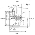
- FIG. 2 shows a plan view of the embodiment of the battery sensor unit 10 according to the invention, the remaining reference numerals with those of FIG. 1 to match.
- the battery sensor unit 10 is connected by means of the clamping body 14, which can be narrowed by the clamping screw 16, with the recessed into a niche 38 or Polish contact 18 and Pol of the battery 20. Due to the cylindrical design of the measuring section 24, a very compact design of the battery sensor unit 10 is possible, so that their dimensions 40 advantageously not exceed the dimensions 42, in particular a longitudinal extent 44 and a width extent 46, the contact niche 38 substantially.
- a battery voltage U is measured via the measuring shunt 28 as a result of a flowing battery current I at a first and second measuring tap 48 or 50 and transferred to a computer unit (not shown), for example a microcontroller, for evaluation.
- the measuring taps 48 and 50 can be attached to the measuring shunt 28 adjacent areas of the cable holder 32 and the fastening device 12 and the copper layer 36 or with a defined distance on the measuring shunt 28.
Landscapes
- Physics & Mathematics (AREA)
- General Physics & Mathematics (AREA)
- Connection Of Batteries Or Terminals (AREA)
- Secondary Cells (AREA)
- Vehicle Body Suspensions (AREA)
- Measuring Fluid Pressure (AREA)
- Arrangement Or Mounting Of Propulsion Units For Vehicles (AREA)
Description
- Die Erfindung betrifft eine Batteriesensoreinheit mit einer Befestigungsvorrichtung und einer Messstrecke sowie ein Verfahren zur Verbindung einer Befestigungsvorrichtung einer Batteriesensoreinheit mit einer Messstrecke nach der Gattung der unabhängigen Ansprüche.
- Zur Batteriezustandserkennung von Batterien in Kraftfahrzeugen werden in der Regel die Größen Temperatur, Strom und/oder Spannung erfasst und mittels geeigneter Algorithmen verarbeitet. Dabei kommt typischerweise in Mikrocontroller oder eine entsprechende Rechnereinheit zum Einsatz. Zur Stromerfassung dienen im Allgemeinen Messshunts und induktive Stromsensoren, wie Kompensationssensoren, Fluxgate- oder Hallelemente.
- Aus der
EP-A 1 435 524 ist eine Batteriesensorvorrichtung mit einer direkt an einen Pol einer Kraftfahrzeugbatterie anschließbaren Befestigungsvorrichtung bekannt, wobei die Befestigungsvorrichtung und ein Batteriesensor zu einer integrierten Baueinheit zusammengefasst sind. Die Batteriesensorvorrichtung ist in Form und Größe an übliche Batteriepolwannen angepasst. Darüber hinaus besteht der Batteriesensor aus einem planaren Messshunt und einer Elektronikeinheit, wobei der Messshunt als Widerstandselement mit zwei als mechanische Träger ausgebildeten Widerstandsanschlüssen ausgestaltet ist. - Aus der
US 5,818,234 ist bereits ein Batterietester bekannt. Dieser überwacht unabhängig sowohl die Temperatur einer Last wie auch die Leistung, die von der Last verbraucht wird. Abgeleitet von diesen Signalen wird der Benutzer gewarnt, wenn das System bestimmte Grenzwerte überschreitet. - Gegenüber dem Stand der Technik weist die erfindungsgemäße Batteriesensoreinheit mit einer Befestigungsvorrichtung zur Befestigung der Batteriesensoreinheit an einen Kontakt einer Batterie, insbesondere einer Kraftfahrzeugbatterie, und mit einer Messstrecke zur Erfassung des Zustands der Batterie, wobei die Messstrecke und die Befestigungsvorrichtung zu einer integralen Baueinheit zusammengefasst sind, den Vorteil auf, dass keine wesentlichen, konstruktiven Modifikationen mehr für eine Änderung der Kabelabgangsrichtung notwendig sind. Zu diesem Zweck ist vorgesehen, dass die Messstrecke zylinderförmig ausgebildet ist. Die Geometrie der Messstrecke gewährleistet damit eine sehr hohe mechanische Festigkeit der Batteriesensoreinheit aufgrund des einsetzbaren Schweißverfahrens bzw. einer in alle Richtungen der Messstrecke nahezu konstanten Biegefestigkeit. Weiterhin ergibt sich hieraus ein deutlicher Kostenvorteil gegenüber der herkömmlichen Anschluss- und Verbindungstechnik.
- In vorteilhafter Weise ist die Messstrecke der Batteriesensoreinheit auf einer ersten Seite mit der Befestigungsvorrichtung verschweißt und auf einer anderen, der ersten Seite gegenüber liegenden Seite mit einer Kabelaufnahme für ein Batteriekabel versehen. Dabei kann die Kabelaufnahme mit dem Batteriekabel mittels Verlöten, Kaltverschweißen oder einer entsprechenden Verbindungstechnik verbunden werden, während sich für die Verbindung zwischen der Befestigungsvorrichtung und der Messstrecke einerseits sowie der Messstrecke und der Kabelaufnahme andererseits ein Reibschweißverfahren anbietet.
- Um die Schweißverbindung und/oder das thermoelektrische Verhalten der Batteriesensoreinheit zu optimieren, ist in einer alternativen Ausgestaltung vorgesehen, zwischen der Messstrecke und der Befestigungsvorrichtung eine Kupferschicht anzuordnen. Die Messstrecke selbst besteht aus einem Widerstandsmaterial, insbesondere Manganin, und ist als ein Messshunt ausgebildet. Darüber hinaus besteht die Möglichkeit, entweder die gesamte Batteriesensoreinheit aus einem Widerstandsmaterial, insbesondere Manganin, herzustellen oder aber die Befestigungsvorrichtung sowie die Kabelaufnahme im Unterschied zur Messstrecke in Kupfer oder einem entsprechenden Material mit sehr guter elektrischer Leitfähigkeit auszubilden.
- In einer vorteilhaften Ausgestaltung bietet sich infolge der sehr kompakten Bauweise an, dass die Ausmaße der Batteriesensoreinheit im Wesentlichen die Ausmaße einer Kontaktnische der Batterie nicht überschreiten, so dass die Batteriesensoreinheit weitestgehend oder vollständig in die Kontaktnische passt und zudem keine konstruktiven Modifikationen für die verschiedenen Kabelabgangsrichtungen erforderlich sind. Dabei umfassen die genannten Ausmaße zumindest eine Längen- und Breitenausdehnung.
- Weitere Vorteile der Erfindung ergeben sich durch die in den abhängigen Ansprüchen angegebenen Merkmale sowie aus der Zeichnung und der nachfolgenden Beschreibung.
- Die Erfindung wird im Folgenden anhand der
Figuren 1 und2 beispielhaft erläutert, wobei gleiche Bezugszeichen in den Figuren auf gleiche Bestandteile mit einer gleichen Funktionsweise hindeuten. Es zeigen -
Fig. 1 : eine erste Ansicht eines Ausführungsbeispiels der erfindungsgemäßen Batteriesensoreinheit und -
Fig. 2 : eine zweite Ansicht des Ausführungsbeispiels der erfindungsgemäßen Batteriesensoreinheit. - In
Figur 1 ist eine erste Ansicht eines Ausführungsbeispiels der erfindungsgemäßen Batteriesensoreinheit 10 gezeigt. Die Batteriesensoreinheit 10 besteht zum Einen aus einer Befestigungsvorrichtung 12, die mittels einer auf einen Klemmkörper 14 wirkenden Klemmschraube 16 in Gestalt einer Polklemme 17 mit einem Kontakt 18 bzw. Pol einer Batterie 20, insbesondere einer Kraftfahrzeugbatterie 22, (sieheFigur 2 ) verbunden werden kann. Zum Anderen besteht die Batteriesensoreinheit 10 aus einer Messstrecke 24, die in einer integralen Baueinheit auf einer ersten Seite 26 mit der Befestigungsvorrichtung 12 zusammengefasst ist. Aufgrund der zylinderförmigen Ausbildung der Messstrecke 24 ergibt sich die Möglichkeit einer kostengünstigen, direkten Reibverschweißung zwischen Messstrecke 24 und Befestigungsvorrichtung 12. Ebenso sind jedoch auch andere Schweißverbindungen denkbar. - Die Messstrecke 24 ist als ein Messshunt 28 ausgebildet und besteht aus einem Widerstandsmaterial, insbesondere Manganin. Während die erste Seite 26 mit der Befestigungsvorrichtung 12 verschweißt ist, weist eine andere, der ersten Seite 26 gegenüber liegende Seite 30 eine Kabelaufnahme 32 für ein Batteriekabel 34 auf, die entweder aus Kupfer oder wie der Messshunt 28 aus einem Widerstandsmaterial bestehen kann und ebenfalls mit der Messstrecke 24 verschweißt ist.
- Um die Schweißverbindung auf der ersten Seite 26 und/oder das thermoelektrische Verhalten der Batteriesensoreinheit 10 zu optimieren, ist zwischen der Messstrecke 24 und der Befestigungsvorrichtung 12 eine Kupferschicht 36 angeordnet. Dies ist insbesondere dann von Vorteil, wenn nicht nur die Messstrecke 24 sondern auch die Befestigungsvorrichtung 12 aus Manganin oder einem anderen Widerstandsmaterial hergestellt sind. Alternativ kann aber auch auf die Kupferschicht 36 verzichtet werden, so dass die gesamte Batteriesensoreinheit 10 inklusive der Kabelaufnahme 32 aus einem Widerstandsmaterial besteht. Ist die Befestigungseinheit 12 dagegen aus Kupfer gefertigt, so ist eine Verwendung der Kupferschicht 36 ohnehin nicht erforderlich.
-
Figur 2 zeigt eine Draufsicht des Ausführungsbeispiels der erfindungsgemäßen Batteriesensoreinheit 10, deren übrige Bezugszeichen mit denen vonFigur 1 übereinstimmen. Die Batteriesensoreinheit 10 ist mittels des Klemmkörpers 14, der durch die Klemmschraube 16 verengt werden kann, mit dem in eine Kontaktnische 38 oder Polnische eingelassenen Kontakt 18 bzw. Pol der Batterie 20 verbindbar. Aufgrund der zylinderförmigen Ausbildung der Messstrecke 24 ist eine sehr kompakte Bauform der Batteriesensoreinheit 10 möglich, so dass deren Ausmaße 40 in vorteilhafter Weise die Ausmaße 42, insbesondere eine Längenausdehnung 44 und eine Breitenausdehnung 46, der Kontaktnische 38 im Wesentlichen nicht überschreiten. - Um den Zustand der Batterie 20 zu erfassen, wird über den Messshunt 28 eine Batteriespannung U infolge eines fließenden Batteriestroms I an einem ersten und zweiten Messabgriff 48 bzw. 50 gemessen und an eine nicht gezeigte Rechnereinheit, beispielsweise einen Mikrocontroller, zur Auswertung übergeben. Die Messabgriffe 48 und 50 können dabei an die dem Messshunt 28 angrenzenden Bereiche der Kabelaufnahme 32 und der Befestigungsvorrichtung 12 bzw. an der Kupferschicht 36 oder mit einem definierten Abstand am Messshunt 28 angebracht sein.
- Es sei abschließend noch darauf hingewiesen, dass das gezeigte Ausführungsbeispiel weder auf die
Figuren 1 und2 noch auf die gezeigte Form der Befestigungsvorrichtung 12 bzw. der verwendeten Klemmschraube 16 sowie der Ausgestaltung der Kabelaufnahme 32 beschränkt ist. So ist beispielsweise ohne Einschränkung der Erfindung eine Abweichung der relativen Größenverhältnisse zwischen Messshunt 28 und Kabelaufnahme 32 bzw. Messstrecke 24 und Befestigungsvorrichtung 12 denkbar.
Claims (11)
- Batteriesensoreinheit (10) mit einer Befestigungsvorrichtung (12) zur Befestigung der Batteriesensoreinheit (10) an einen Kontakt (18) einer Batterie (20), insbesondere einer Kraftfahrzeugbatterie (22), und mit einer Messstrecke (24) zur Erfassung des Zustands der Batterie (20) wobei die Messstrecke (24) als ein Messshunt (28) ausgebildet ist und, wobei die Messstrecke (24) und die Befestigungsvorrichtung (12) zu einer integralen Baueinheit zusammengefasst sind, wobei die Messstrecke (24) zylinderförmig ausgebildet ist, dadurch gekennzeichnet, dass die Messstrecke (24) auf einer ersten Seite (26) mit der Befestigungsvorrichtung (12) verschweißt ist und auf einer anderen, der ersten Seite (26) gegenüber liegenden Seite (30) eine Kabelaufnahme (32) für ein Batteriekabel (34) aufweist.
- Batteriesensoreinheit (10) nach Anspruch 1, dadurch gekennzeichnet, dass die Messstrecke (24) aus einem Widerstandsmaterial, insbesondere Manganin, besteht.
- Batteriesensoreinheit (10) nach einem der vorhergehenden Ansprüche, dadurch gekennzeichnet, dass zwischen der Messstrecke (24) und der Befestigungsvorrichtung (12) eine Kupferschicht (36) angeordnet ist.
- Batteriesensoreinheit (10) nach einem der vorhergehenden Ansprüche, dadurch gekennzeichnet, dass die Befestigungsvorrichtung (12) eine Polklemme (17) ist.
- Batteriesensoreinheit (10) nach Anspruch 1, dadurch gekennzeichnet, dass die gesamte Batteriesensoreinheit (10) aus einem Widerstandsmaterial, insbesondere Manganin, besteht.
- Batteriesensoreinheit (10) nach einem der vorhergehenden Ansprüche, gekennzeichnet durch Ausmaße (40), die im Wesentlichen die Ausmaße (42) einer Kontaktnische (38) der Batterie (20) nicht überschreiten.
- Batteriesensoreinheit (10) nach Anspruch 5, dadurch gekennzeichnet, dass die Ausmaße (40) zumindest eine Längenausdehnung (44) und eine Breitenausdehnung (46) umfassen.
- Verfahren zur Verbindung einer Befestigungsvorrichtung (12) einer Batteriesensoreinheit (10) mit einer als Messhunt (28) ausgebildeten Messstrecke (24), wobei die Messstrecke (24) zylinderförmig ausgebildet ist und auf einer ersten Seite (26) mit der Befestigungsvorrichtung (12) in einer integralen Baueinheit verschweißt wird, dadurch gekennzeichnet, dass die Messstrecke (24) auf einer weiteren, der ersten Seite (26) gegenüber liegenden Seite (30) eine Kabelaufnahme (32) aufweist, die mit einem Batteriekabel (34) verbunden wird.
- Verfahren nach Anspruch 9, dadurch gekennzeichnet, dass die Messtrecke (24) und die Befestigungsvorrichtung (12) durch Reibschweißen miteinander verbunden werden.
- Verfahren nach einem der vorherigen Ansprüche 8 oder 9, dadurch gekennzeichnet, dass zwischen der Messstrecke (24) und der Befestigungsvorrichtung (12) eine Kupferschicht (36) eingefügt wird.
- Verfahren nach einem der vorhergehenden Ansprüche 8 bis 10, dadurch gekennzeichnet, dass die Befestigungsvorrichtung (12) eine Polklemme (17) ist.
Applications Claiming Priority (2)
| Application Number | Priority Date | Filing Date | Title |
|---|---|---|---|
| DE102005039587A DE102005039587A1 (de) | 2005-08-19 | 2005-08-19 | Batteriesensoreinheit |
| PCT/EP2006/063828 WO2007020129A1 (de) | 2005-08-19 | 2006-07-04 | Batteriesensoreinheit |
Publications (2)
| Publication Number | Publication Date |
|---|---|
| EP1920264A1 EP1920264A1 (de) | 2008-05-14 |
| EP1920264B1 true EP1920264B1 (de) | 2010-01-27 |
Family
ID=36995852
Family Applications (1)
| Application Number | Title | Priority Date | Filing Date |
|---|---|---|---|
| EP06777559A Not-in-force EP1920264B1 (de) | 2005-08-19 | 2006-07-04 | Batteriesensoreinheit |
Country Status (5)
| Country | Link |
|---|---|
| US (1) | US20090212779A1 (de) |
| EP (1) | EP1920264B1 (de) |
| AT (1) | ATE456806T1 (de) |
| DE (2) | DE102005039587A1 (de) |
| WO (1) | WO2007020129A1 (de) |
Cited By (1)
| Publication number | Priority date | Publication date | Assignee | Title |
|---|---|---|---|---|
| DE102012200508A1 (de) | 2012-01-13 | 2013-07-18 | Robert Bosch Gmbh | Batteriesensor |
Families Citing this family (20)
| Publication number | Priority date | Publication date | Assignee | Title |
|---|---|---|---|---|
| US7688022B2 (en) * | 2006-02-17 | 2010-03-30 | Lear Corporation | Energy management system for a vehicle |
| US8476864B2 (en) * | 2007-06-13 | 2013-07-02 | Lear Corporation | Battery monitoring system |
| US7663376B2 (en) * | 2007-08-06 | 2010-02-16 | Lear Corporation | Printed circuit board for sensing voltage drop |
| DE102007054396A1 (de) | 2007-11-14 | 2009-05-20 | Robert Bosch Gmbh | Batterie, insbesondere für ein Kraftfahrzeug, mit einer Vorrichtung und einem Verfahren zum Laden der Batterie |
| DE102007060940A1 (de) | 2007-12-18 | 2009-06-25 | Robert Bosch Gmbh | Sensoranordnung für die Zustandserkennung einer Batterie |
| DE102007061112A1 (de) | 2007-12-19 | 2009-06-25 | Robert Bosch Gmbh | Sensoranordnung und Diagnoseverfahren für die Zustandserkennung einer Batterie und/oder elektrischer Verbraucher in einem Kraftfahrzeug |
| DE102007061113A1 (de) | 2007-12-19 | 2009-06-25 | Robert Bosch Gmbh | Sensoranordnung für die Zustandserkennung einer Batterie |
| DE102007061111A1 (de) | 2007-12-19 | 2009-06-25 | Robert Bosch Gmbh | Sensoranordnung und Diagnoseverfahren für die Zustandserkennung einer Batterie in einem Kraftfahrzeug |
| DE102008013408A1 (de) | 2008-03-10 | 2009-09-17 | Robert Bosch Gmbh | Shuntwiderstand mit Messschaltung |
| DE102008013407A1 (de) | 2008-03-10 | 2009-09-17 | Robert Bosch Gmbh | Sensoranordnung für die Zustandserkennung einer Batterie |
| DE102008002308A1 (de) | 2008-06-09 | 2009-12-10 | Robert Bosch Gmbh | Polklemmenanordnung mit integriertem Shuntwiderstand |
| DE102008040243A1 (de) | 2008-07-08 | 2010-01-14 | Robert Bosch Gmbh | Polklemmenanordnung mit integriertem Shuntwiderstand |
| US8305034B2 (en) * | 2008-07-23 | 2012-11-06 | Lear Corporation | Battery monitoring system |
| DE102008041539A1 (de) | 2008-08-26 | 2010-03-04 | Robert Bosch Gmbh | Shuntwiderstand mit Auswerteschaltung |
| DE102009000225A1 (de) | 2009-01-14 | 2010-07-15 | Robert Bosch Gmbh | Batterie mit integriertem Stromsensor |
| DE102013221210A1 (de) | 2013-10-18 | 2015-04-23 | Continental Teves Ag & Co. Ohg | Verfahren zum Messen einer Temperatur |
| US10062931B2 (en) | 2015-04-22 | 2018-08-28 | Johnson Controls Technology Company | Welding process for battery module components |
| CN107402184B (zh) * | 2016-05-20 | 2020-01-03 | 清华大学 | 一种测量纳米结构表面电荷分布的方法 |
| US9929478B1 (en) * | 2017-02-02 | 2018-03-27 | Ayele W. Bellete | Battery terminal connector with connectors of different shape for positive and negative cables |
| WO2020078814A1 (de) * | 2018-10-15 | 2020-04-23 | Continental Automotive Gmbh | Widerstandsbaugruppe und verfahren zur herstellung einer widerstandsbaugruppe und batteriesensor |
Family Cites Families (20)
| Publication number | Priority date | Publication date | Assignee | Title |
|---|---|---|---|---|
| US3401337A (en) * | 1964-04-09 | 1968-09-10 | Union Carbide Corp | Connector device for connecting a battery terminal with a batterylife indicator meter |
| DE3532044A1 (de) * | 1985-09-09 | 1987-03-19 | Vdo Schindling | Polklemme |
| US4973937A (en) * | 1989-03-13 | 1990-11-27 | Barnet Weinstein | Electrical shunt apparatus |
| US5818234A (en) * | 1996-05-08 | 1998-10-06 | Ferret Instruments, Inc. | Battery tester with power limit detection |
| DK0990167T3 (da) * | 1998-04-17 | 2006-09-18 | Systemtechnik Ag Ak | Batterimåleterminal |
| DE19961311A1 (de) * | 1999-12-18 | 2001-07-26 | Bayerische Motoren Werke Ag | Batteriesensorvorrichtung |
| US6347958B1 (en) * | 2000-09-18 | 2002-02-19 | Real Power Cap Company | Connecting device to vehicle battery terminals |
| JP3697154B2 (ja) * | 2000-11-01 | 2005-09-21 | 住友電装株式会社 | 電流センサ付きバッテリターミナル |
| US6469511B1 (en) * | 2001-07-18 | 2002-10-22 | Midtronics, Inc. | Battery clamp with embedded environment sensor |
| US6544078B2 (en) * | 2001-07-18 | 2003-04-08 | Midtronics, Inc. | Battery clamp with integrated current sensor |
| JP4103713B2 (ja) * | 2003-07-18 | 2008-06-18 | 株式会社デンソー | 電流検出器 |
| US6972544B2 (en) * | 2003-10-14 | 2005-12-06 | Black & Decker Inc. | Apparatus for interconnecting battery cells in a battery pack and method thereof |
| DE102004006298B4 (de) * | 2004-02-09 | 2006-08-17 | Siemens Ag | Verbindungsanordnung für ein Messelement eines Batteriesensors |
| JP2006085945A (ja) * | 2004-09-14 | 2006-03-30 | Denso Corp | 電流センサの取付け構造 |
| DE102004053648A1 (de) * | 2004-11-03 | 2006-05-04 | Leopold Kostal Gmbh & Co. Kg | Batteriestromsensor für ein Kraftfahrzeug |
| FR2879751B1 (fr) * | 2004-12-20 | 2007-02-23 | Johnson Controls Tech Co | Dispositif de mesure d'un courant circulant dans un cable |
| US7688022B2 (en) * | 2006-02-17 | 2010-03-30 | Lear Corporation | Energy management system for a vehicle |
| DE102006029547A1 (de) * | 2006-06-26 | 2007-12-27 | Robert Bosch Gmbh | Batteriesensoreinheit und Verfahren zur Herstellung der Batteriesensoreinheit |
| DE102006038373A1 (de) * | 2006-08-12 | 2008-02-14 | Robert Bosch Gmbh | Elektrische Vorrichtung |
| DE102006046137B4 (de) * | 2006-09-28 | 2019-02-14 | Continental Automotive Gmbh | Batteriesensoreinheit |
-
2005
- 2005-08-19 DE DE102005039587A patent/DE102005039587A1/de not_active Withdrawn
-
2006
- 2006-07-04 WO PCT/EP2006/063828 patent/WO2007020129A1/de not_active Ceased
- 2006-07-04 EP EP06777559A patent/EP1920264B1/de not_active Not-in-force
- 2006-07-04 AT AT06777559T patent/ATE456806T1/de active
- 2006-07-04 DE DE502006006049T patent/DE502006006049D1/de active Active
- 2006-07-04 US US11/989,465 patent/US20090212779A1/en not_active Abandoned
Cited By (1)
| Publication number | Priority date | Publication date | Assignee | Title |
|---|---|---|---|---|
| DE102012200508A1 (de) | 2012-01-13 | 2013-07-18 | Robert Bosch Gmbh | Batteriesensor |
Also Published As
| Publication number | Publication date |
|---|---|
| WO2007020129A1 (de) | 2007-02-22 |
| ATE456806T1 (de) | 2010-02-15 |
| US20090212779A1 (en) | 2009-08-27 |
| EP1920264A1 (de) | 2008-05-14 |
| DE502006006049D1 (de) | 2010-03-18 |
| DE102005039587A1 (de) | 2007-02-22 |
Similar Documents
| Publication | Publication Date | Title |
|---|---|---|
| EP1920264B1 (de) | Batteriesensoreinheit | |
| EP2036099B1 (de) | Batteriesensoreinheit und verfahren zur herstellung der batteriesensoreinheit | |
| EP2946220B1 (de) | Messanordnung mit einem messwiderstand | |
| EP1890162B1 (de) | Elektrische Mess-Vorrichtung | |
| DE102004006298B4 (de) | Verbindungsanordnung für ein Messelement eines Batteriesensors | |
| DE102007009569B4 (de) | Anschlusseinrichtung und Verfahren zu deren Herstellung | |
| WO2010023004A1 (de) | Shuntwiderstand mit auswerteschaltung | |
| DE102004046855B3 (de) | Batteriepolklemmenanordnung | |
| DE102007018669A1 (de) | Batteriepolmessklemme mit Schutzelement | |
| DE102017200050A1 (de) | Anschlussmodul für einen elektrischen Energiespeicher sowie Energieversorgungssystem | |
| EP2732488B1 (de) | Vorrichtung zum führen eines elektrischen stromes | |
| DE102017003111A1 (de) | Stromsensor mit Diagnose | |
| DE102007006050B4 (de) | Anschlusseinrichtung | |
| DE102006029731B4 (de) | Batterieanschluss | |
| EP3671241A1 (de) | Widerstandsbaugruppe für einen batteriesensor und batteriesensor | |
| EP1921456B1 (de) | Kraftfahrzeugsensor, insbesondere Batteriesensor, mit Messwiderstand | |
| DE102021122162A1 (de) | Kompakter messfühler für messungen an einem batteriemodul | |
| DE102013220516A1 (de) | Messeinrichtung | |
| DE102021112964A1 (de) | Strommessanordnung mit Temperatureffektkompensation, deren Verwendung in einem Kraftfahrzeug sowie zugehöriges Verfahren zur Strommessung | |
| EP1362391B1 (de) | Anschlussklemme | |
| DE102005032227B4 (de) | System zur Ruhestrommessung in Kraftfahrzeugen | |
| DE10357524B4 (de) | Strommesseinrichtung | |
| WO2020078814A1 (de) | Widerstandsbaugruppe und verfahren zur herstellung einer widerstandsbaugruppe und batteriesensor | |
| EP3335054A1 (de) | Batteriesensoreinheit mit hoher mechanischer robustheit | |
| DE102018200621A1 (de) | Messanordnung mit einem Messwiderstand |
Legal Events
| Date | Code | Title | Description |
|---|---|---|---|
| PUAI | Public reference made under article 153(3) epc to a published international application that has entered the european phase |
Free format text: ORIGINAL CODE: 0009012 |
|
| 17P | Request for examination filed |
Effective date: 20080319 |
|
| AK | Designated contracting states |
Kind code of ref document: A1 Designated state(s): AT BE BG CH CY CZ DE DK EE ES FI FR GB GR HU IE IS IT LI LT LU LV MC NL PL PT RO SE SI SK TR |
|
| 17Q | First examination report despatched |
Effective date: 20081111 |
|
| GRAP | Despatch of communication of intention to grant a patent |
Free format text: ORIGINAL CODE: EPIDOSNIGR1 |
|
| GRAS | Grant fee paid |
Free format text: ORIGINAL CODE: EPIDOSNIGR3 |
|
| GRAA | (expected) grant |
Free format text: ORIGINAL CODE: 0009210 |
|
| AK | Designated contracting states |
Kind code of ref document: B1 Designated state(s): AT BE BG CH CY CZ DE DK EE ES FI FR GB GR HU IE IS IT LI LT LU LV MC NL PL PT RO SE SI SK TR |
|
| REG | Reference to a national code |
Ref country code: GB Ref legal event code: FG4D Free format text: NOT ENGLISH |
|
| REG | Reference to a national code |
Ref country code: CH Ref legal event code: EP |
|
| REG | Reference to a national code |
Ref country code: IE Ref legal event code: FG4D |
|
| REF | Corresponds to: |
Ref document number: 502006006049 Country of ref document: DE Date of ref document: 20100318 Kind code of ref document: P |
|
| REG | Reference to a national code |
Ref country code: NL Ref legal event code: VDEP Effective date: 20100127 |
|
| LTIE | Lt: invalidation of european patent or patent extension |
Effective date: 20100127 |
|
| PG25 | Lapsed in a contracting state [announced via postgrant information from national office to epo] |
Ref country code: NL Free format text: LAPSE BECAUSE OF FAILURE TO SUBMIT A TRANSLATION OF THE DESCRIPTION OR TO PAY THE FEE WITHIN THE PRESCRIBED TIME-LIMIT Effective date: 20100127 Ref country code: IS Free format text: LAPSE BECAUSE OF FAILURE TO SUBMIT A TRANSLATION OF THE DESCRIPTION OR TO PAY THE FEE WITHIN THE PRESCRIBED TIME-LIMIT Effective date: 20100527 Ref country code: PT Free format text: LAPSE BECAUSE OF FAILURE TO SUBMIT A TRANSLATION OF THE DESCRIPTION OR TO PAY THE FEE WITHIN THE PRESCRIBED TIME-LIMIT Effective date: 20100527 Ref country code: ES Free format text: LAPSE BECAUSE OF FAILURE TO SUBMIT A TRANSLATION OF THE DESCRIPTION OR TO PAY THE FEE WITHIN THE PRESCRIBED TIME-LIMIT Effective date: 20100508 Ref country code: LT Free format text: LAPSE BECAUSE OF FAILURE TO SUBMIT A TRANSLATION OF THE DESCRIPTION OR TO PAY THE FEE WITHIN THE PRESCRIBED TIME-LIMIT Effective date: 20100127 |
|
| REG | Reference to a national code |
Ref country code: IE Ref legal event code: FD4D |
|
| PG25 | Lapsed in a contracting state [announced via postgrant information from national office to epo] |
Ref country code: PL Free format text: LAPSE BECAUSE OF FAILURE TO SUBMIT A TRANSLATION OF THE DESCRIPTION OR TO PAY THE FEE WITHIN THE PRESCRIBED TIME-LIMIT Effective date: 20100127 Ref country code: SI Free format text: LAPSE BECAUSE OF FAILURE TO SUBMIT A TRANSLATION OF THE DESCRIPTION OR TO PAY THE FEE WITHIN THE PRESCRIBED TIME-LIMIT Effective date: 20100127 Ref country code: LV Free format text: LAPSE BECAUSE OF FAILURE TO SUBMIT A TRANSLATION OF THE DESCRIPTION OR TO PAY THE FEE WITHIN THE PRESCRIBED TIME-LIMIT Effective date: 20100127 Ref country code: FI Free format text: LAPSE BECAUSE OF FAILURE TO SUBMIT A TRANSLATION OF THE DESCRIPTION OR TO PAY THE FEE WITHIN THE PRESCRIBED TIME-LIMIT Effective date: 20100127 |
|
| PG25 | Lapsed in a contracting state [announced via postgrant information from national office to epo] |
Ref country code: GR Free format text: LAPSE BECAUSE OF FAILURE TO SUBMIT A TRANSLATION OF THE DESCRIPTION OR TO PAY THE FEE WITHIN THE PRESCRIBED TIME-LIMIT Effective date: 20100428 Ref country code: IE Free format text: LAPSE BECAUSE OF FAILURE TO SUBMIT A TRANSLATION OF THE DESCRIPTION OR TO PAY THE FEE WITHIN THE PRESCRIBED TIME-LIMIT Effective date: 20100127 Ref country code: RO Free format text: LAPSE BECAUSE OF FAILURE TO SUBMIT A TRANSLATION OF THE DESCRIPTION OR TO PAY THE FEE WITHIN THE PRESCRIBED TIME-LIMIT Effective date: 20100127 Ref country code: SE Free format text: LAPSE BECAUSE OF FAILURE TO SUBMIT A TRANSLATION OF THE DESCRIPTION OR TO PAY THE FEE WITHIN THE PRESCRIBED TIME-LIMIT Effective date: 20100127 Ref country code: CY Free format text: LAPSE BECAUSE OF FAILURE TO SUBMIT A TRANSLATION OF THE DESCRIPTION OR TO PAY THE FEE WITHIN THE PRESCRIBED TIME-LIMIT Effective date: 20100127 Ref country code: EE Free format text: LAPSE BECAUSE OF FAILURE TO SUBMIT A TRANSLATION OF THE DESCRIPTION OR TO PAY THE FEE WITHIN THE PRESCRIBED TIME-LIMIT Effective date: 20100127 |
|
| PG25 | Lapsed in a contracting state [announced via postgrant information from national office to epo] |
Ref country code: CZ Free format text: LAPSE BECAUSE OF FAILURE TO SUBMIT A TRANSLATION OF THE DESCRIPTION OR TO PAY THE FEE WITHIN THE PRESCRIBED TIME-LIMIT Effective date: 20100127 Ref country code: SK Free format text: LAPSE BECAUSE OF FAILURE TO SUBMIT A TRANSLATION OF THE DESCRIPTION OR TO PAY THE FEE WITHIN THE PRESCRIBED TIME-LIMIT Effective date: 20100127 Ref country code: BG Free format text: LAPSE BECAUSE OF FAILURE TO SUBMIT A TRANSLATION OF THE DESCRIPTION OR TO PAY THE FEE WITHIN THE PRESCRIBED TIME-LIMIT Effective date: 20100427 |
|
| PLBE | No opposition filed within time limit |
Free format text: ORIGINAL CODE: 0009261 |
|
| STAA | Information on the status of an ep patent application or granted ep patent |
Free format text: STATUS: NO OPPOSITION FILED WITHIN TIME LIMIT |
|
| 26N | No opposition filed |
Effective date: 20101028 |
|
| BERE | Be: lapsed |
Owner name: ROBERT BOSCH G.M.B.H. Effective date: 20100731 |
|
| PG25 | Lapsed in a contracting state [announced via postgrant information from national office to epo] |
Ref country code: DK Free format text: LAPSE BECAUSE OF FAILURE TO SUBMIT A TRANSLATION OF THE DESCRIPTION OR TO PAY THE FEE WITHIN THE PRESCRIBED TIME-LIMIT Effective date: 20100127 |
|
| PG25 | Lapsed in a contracting state [announced via postgrant information from national office to epo] |
Ref country code: MC Free format text: LAPSE BECAUSE OF NON-PAYMENT OF DUE FEES Effective date: 20100731 |
|
| REG | Reference to a national code |
Ref country code: CH Ref legal event code: PL |
|
| GBPC | Gb: european patent ceased through non-payment of renewal fee |
Effective date: 20100704 |
|
| PG25 | Lapsed in a contracting state [announced via postgrant information from national office to epo] |
Ref country code: IT Free format text: LAPSE BECAUSE OF FAILURE TO SUBMIT A TRANSLATION OF THE DESCRIPTION OR TO PAY THE FEE WITHIN THE PRESCRIBED TIME-LIMIT Effective date: 20100127 |
|
| PG25 | Lapsed in a contracting state [announced via postgrant information from national office to epo] |
Ref country code: LI Free format text: LAPSE BECAUSE OF NON-PAYMENT OF DUE FEES Effective date: 20100731 Ref country code: CH Free format text: LAPSE BECAUSE OF NON-PAYMENT OF DUE FEES Effective date: 20100731 |
|
| REG | Reference to a national code |
Ref country code: HU Ref legal event code: AG4A Ref document number: E010008 Country of ref document: HU |
|
| PG25 | Lapsed in a contracting state [announced via postgrant information from national office to epo] |
Ref country code: BE Free format text: LAPSE BECAUSE OF NON-PAYMENT OF DUE FEES Effective date: 20100731 |
|
| PG25 | Lapsed in a contracting state [announced via postgrant information from national office to epo] |
Ref country code: GB Free format text: LAPSE BECAUSE OF NON-PAYMENT OF DUE FEES Effective date: 20100704 |
|
| PG25 | Lapsed in a contracting state [announced via postgrant information from national office to epo] |
Ref country code: LU Free format text: LAPSE BECAUSE OF NON-PAYMENT OF DUE FEES Effective date: 20100704 |
|
| PG25 | Lapsed in a contracting state [announced via postgrant information from national office to epo] |
Ref country code: TR Free format text: LAPSE BECAUSE OF FAILURE TO SUBMIT A TRANSLATION OF THE DESCRIPTION OR TO PAY THE FEE WITHIN THE PRESCRIBED TIME-LIMIT Effective date: 20100127 |
|
| REG | Reference to a national code |
Ref country code: AT Ref legal event code: MM01 Ref document number: 456806 Country of ref document: AT Kind code of ref document: T Effective date: 20110704 |
|
| PG25 | Lapsed in a contracting state [announced via postgrant information from national office to epo] |
Ref country code: AT Free format text: LAPSE BECAUSE OF NON-PAYMENT OF DUE FEES Effective date: 20110704 |
|
| PGFP | Annual fee paid to national office [announced via postgrant information from national office to epo] |
Ref country code: DE Payment date: 20140925 Year of fee payment: 9 |
|
| REG | Reference to a national code |
Ref country code: FR Ref legal event code: PLFP Year of fee payment: 10 |
|
| PGFP | Annual fee paid to national office [announced via postgrant information from national office to epo] |
Ref country code: HU Payment date: 20150626 Year of fee payment: 10 Ref country code: FR Payment date: 20150730 Year of fee payment: 10 |
|
| REG | Reference to a national code |
Ref country code: DE Ref legal event code: R119 Ref document number: 502006006049 Country of ref document: DE |
|
| PG25 | Lapsed in a contracting state [announced via postgrant information from national office to epo] |
Ref country code: DE Free format text: LAPSE BECAUSE OF NON-PAYMENT OF DUE FEES Effective date: 20160202 |
|
| PG25 | Lapsed in a contracting state [announced via postgrant information from national office to epo] |
Ref country code: HU Free format text: LAPSE BECAUSE OF NON-PAYMENT OF DUE FEES Effective date: 20160705 Ref country code: FR Free format text: LAPSE BECAUSE OF NON-PAYMENT OF DUE FEES Effective date: 20160801 |
|
| REG | Reference to a national code |
Ref country code: FR Ref legal event code: ST Effective date: 20170331 |