EP1919833B1 - Waste water purifying device - Google Patents
Waste water purifying device Download PDFInfo
- Publication number
- EP1919833B1 EP1919833B1 EP06776841A EP06776841A EP1919833B1 EP 1919833 B1 EP1919833 B1 EP 1919833B1 EP 06776841 A EP06776841 A EP 06776841A EP 06776841 A EP06776841 A EP 06776841A EP 1919833 B1 EP1919833 B1 EP 1919833B1
- Authority
- EP
- European Patent Office
- Prior art keywords
- level
- tank
- aerated
- chamber
- labyrinth
- Prior art date
- Legal status (The legal status is an assumption and is not a legal conclusion. Google has not performed a legal analysis and makes no representation as to the accuracy of the status listed.)
- Active
Links
- 239000002351 wastewater Substances 0.000 title claims abstract description 24
- 239000010802 sludge Substances 0.000 claims abstract description 36
- 230000014759 maintenance of location Effects 0.000 claims abstract description 13
- 238000000034 method Methods 0.000 claims abstract description 13
- 238000004062 sedimentation Methods 0.000 claims abstract description 12
- 230000008569 process Effects 0.000 claims abstract description 11
- 238000005192 partition Methods 0.000 claims description 41
- XLYOFNOQVPJJNP-UHFFFAOYSA-N water Substances O XLYOFNOQVPJJNP-UHFFFAOYSA-N 0.000 claims description 38
- 229920003023 plastic Polymers 0.000 claims description 8
- 239000004033 plastic Substances 0.000 claims description 8
- 239000000463 material Substances 0.000 claims description 4
- 239000012530 fluid Substances 0.000 claims description 3
- 238000007664 blowing Methods 0.000 claims 1
- 239000012535 impurity Substances 0.000 claims 1
- 238000004065 wastewater treatment Methods 0.000 description 31
- 239000010865 sewage Substances 0.000 description 30
- 230000001681 protective effect Effects 0.000 description 10
- 238000010276 construction Methods 0.000 description 9
- 239000004698 Polyethylene Substances 0.000 description 8
- 239000004743 Polypropylene Substances 0.000 description 8
- 238000004140 cleaning Methods 0.000 description 8
- -1 polyethylene Polymers 0.000 description 8
- 229920000573 polyethylene Polymers 0.000 description 8
- 229920001155 polypropylene Polymers 0.000 description 8
- 238000004519 manufacturing process Methods 0.000 description 6
- 238000002156 mixing Methods 0.000 description 5
- 239000000203 mixture Substances 0.000 description 5
- 238000000746 purification Methods 0.000 description 5
- 238000003911 water pollution Methods 0.000 description 5
- IJGRMHOSHXDMSA-UHFFFAOYSA-N Atomic nitrogen Chemical compound N#N IJGRMHOSHXDMSA-UHFFFAOYSA-N 0.000 description 4
- 238000001994 activation Methods 0.000 description 4
- 238000005352 clarification Methods 0.000 description 4
- 239000004800 polyvinyl chloride Substances 0.000 description 4
- 229920000915 polyvinyl chloride Polymers 0.000 description 4
- 230000000750 progressive effect Effects 0.000 description 4
- 230000000694 effects Effects 0.000 description 3
- 239000002689 soil Substances 0.000 description 3
- 241001503485 Mammuthus Species 0.000 description 2
- OAICVXFJPJFONN-UHFFFAOYSA-N Phosphorus Chemical compound [P] OAICVXFJPJFONN-UHFFFAOYSA-N 0.000 description 2
- 238000005273 aeration Methods 0.000 description 2
- 230000007812 deficiency Effects 0.000 description 2
- 230000008030 elimination Effects 0.000 description 2
- 238000003379 elimination reaction Methods 0.000 description 2
- 238000005516 engineering process Methods 0.000 description 2
- 238000011010 flushing procedure Methods 0.000 description 2
- 230000007246 mechanism Effects 0.000 description 2
- 229910052757 nitrogen Inorganic materials 0.000 description 2
- 210000003903 pelvic floor Anatomy 0.000 description 2
- 229910052698 phosphorus Inorganic materials 0.000 description 2
- 239000011574 phosphorus Substances 0.000 description 2
- 238000005086 pumping Methods 0.000 description 2
- 239000002352 surface water Substances 0.000 description 2
- 239000003643 water by type Substances 0.000 description 2
- 230000009471 action Effects 0.000 description 1
- 230000004913 activation Effects 0.000 description 1
- 230000008901 benefit Effects 0.000 description 1
- 238000006243 chemical reaction Methods 0.000 description 1
- 125000004122 cyclic group Chemical group 0.000 description 1
- 230000008021 deposition Effects 0.000 description 1
- 230000004720 fertilization Effects 0.000 description 1
- 230000005484 gravity Effects 0.000 description 1
- 239000003673 groundwater Substances 0.000 description 1
- 238000011065 in-situ storage Methods 0.000 description 1
- 230000008595 infiltration Effects 0.000 description 1
- 238000001764 infiltration Methods 0.000 description 1
- 230000035699 permeability Effects 0.000 description 1
- 238000010926 purge Methods 0.000 description 1
- 238000000926 separation method Methods 0.000 description 1
- 238000012163 sequencing technique Methods 0.000 description 1
- 239000000126 substance Substances 0.000 description 1
- 238000009423 ventilation Methods 0.000 description 1
Images


Classifications
-
- C—CHEMISTRY; METALLURGY
- C02—TREATMENT OF WATER, WASTE WATER, SEWAGE, OR SLUDGE
- C02F—TREATMENT OF WATER, WASTE WATER, SEWAGE, OR SLUDGE
- C02F3/00—Biological treatment of water, waste water, or sewage
- C02F3/30—Aerobic and anaerobic processes
-
- C—CHEMISTRY; METALLURGY
- C02—TREATMENT OF WATER, WASTE WATER, SEWAGE, OR SLUDGE
- C02F—TREATMENT OF WATER, WASTE WATER, SEWAGE, OR SLUDGE
- C02F3/00—Biological treatment of water, waste water, or sewage
- C02F3/02—Aerobic processes
- C02F3/12—Activated sludge processes
- C02F3/1236—Particular type of activated sludge installations
- C02F3/1242—Small compact installations for use in homes, apartment blocks, hotels or the like
-
- Y—GENERAL TAGGING OF NEW TECHNOLOGICAL DEVELOPMENTS; GENERAL TAGGING OF CROSS-SECTIONAL TECHNOLOGIES SPANNING OVER SEVERAL SECTIONS OF THE IPC; TECHNICAL SUBJECTS COVERED BY FORMER USPC CROSS-REFERENCE ART COLLECTIONS [XRACs] AND DIGESTS
- Y02—TECHNOLOGIES OR APPLICATIONS FOR MITIGATION OR ADAPTATION AGAINST CLIMATE CHANGE
- Y02W—CLIMATE CHANGE MITIGATION TECHNOLOGIES RELATED TO WASTEWATER TREATMENT OR WASTE MANAGEMENT
- Y02W10/00—Technologies for wastewater treatment
- Y02W10/10—Biological treatment of water, waste water, or sewage
Definitions
- the invention relates to a device for continuous, biological wastewater treatment from smaller sources of water pollution with a modified activation process, in which in a pool a living space with space-isolated, anaerobic, anoxic and oxic zones is combined and a secondary clarifier is combined with a retention space, with an existing circuit between the Zones of the living space and between the living space and the secondary room.
- Wastewater treatment from smaller sources of water pollution is a complicated problem, because of the problems of considerable variability of wastewater flows and the variability of wastewater flows Water pollution faced by these smaller sources. In relatively small sections of the collecting channel, it does not balance the amount of sewage and sewage quality. Therefore, one must adapt the individual technical stages of the process of wastewater treatment (equalization tank, mechanical and biological cleaning and eventual subsequent cleaning) so that they are not overwhelmed and thus the necessary residence time and the surface load in the secondary clarification room are not exceeded. If no conditions have been established for balancing the quality and quantity of the wastewater flow, these stages must be significantly oversized. Wastewater treatment plants are dimensioned for the average flow rate of Q 24 . The hourly unevenness of the flow expresses another dimensioned flow, the maximum hourly flow Qmax.
- a filter device is described in a discharge line, which is used in the secondary clarifier.
- This filter device has a certain filter capacity; if the sewage inflow is greater than the filter capacity, the (water) level in the entire reactor increases, whereby a larger part of the filter submerges and thus increase the area and thus the filter capacity.
- the filter is rinsed again with pressurized water supplied by a submersible pump placed behind the reactor in a basin of clear water.
- a drawback is that for the water used to rinse the filter device, another basin must be set up where the purified waste water collects and a pump is attached with a reusable control valve. However, this increases the investment and operating costs of wastewater treatment.
- the smaller wastewater treatment plants In the design and implementation of the smaller wastewater treatment plants, it is necessary that the smaller wastewater treatment plants be easily transportable finished products or be assembled in situ and adapt to the conditions of the application or the landscape with a minimum of construction work with the outer shapes, so that they are adaptable and parallel with the Increase in the amount of wastewater produced can be extended. Smaller wastewater treatment plants with an integrated retention space do not allow the fulfillment of all these requirements in the current state of the art at the same time.
- the object of the invention is to provide a device for wastewater treatment from smaller sources of water pollution, which can be made in a compact unit with the possibility of formability and changeability by the use of a simple concrete support frame and lightweight construction wall elements made of plastic.
- This device should perform the task of balancing the variable flow in a functional unit and achieve the highest possible efficiency of biological purification with elimination of nitrogen and phosphorus with low demands on the pump and mixing technology.
- This object and the deficiencies of the known devices solves or substantially eliminates the device for continuous biological wastewater treatment with a modified activated sludge process in a basin a vital space with unventilated, anaerobic and anoxic zones with a ventilated, oxic zone and a secondary clarifier a retention space combined with an internal return between the zones of the living space and a recirculation of the return sludge between the living space and secondary clarification according to the invention.
- the essence of the invention is that the basin, which consists of a bottom and an outer shell, is divided into an unvented, vertically traversed labyrinth, a ventilated Belocatingraum, a NachJacquesraum and a retention space that the unventilated, vertically traversed labyrinth of the ventilated Living space is separated by a partition that extends from the floor to above the level of the maximum level (B) passing through the plane of the Flood relief system is given, and having a passage opening either at the level of the basin or at the level of the outlet pipe from the basin.
- B maximum level
- the secondary clarifying room is confined inside the ventilated living space by a jacket extending from the floor to above the level of the maximum level (B) provided by the level of the spillway and has a passage opening at the bottom level of the basin.
- the retention space is located in the basin between the level of the minimum level (A), which is given by the effluent out of the basin outflow line, and the level of the maximum water level (B), which is given by the level of the spillway, on the whole area along the vertical labyrinth, the ventilated living space and the secondary sedimentation chamber.
- the vertically traversed labyrinth is divided in the direction of flow by dividing walls that protrude from the floor to above the level of the maximum level (B), which is given by the level of the spillway and the further passage openings alternately at the bottom level of the basin and at the level of the minimum Level (A), which is given by the purging out of the basin outflow line, wherein in the final sedimentation on the leading out of the basin outflow line, a flow regulator with a calibrated throttle opening is mounted.
- the dimensioned on the effluent line from the facility comes to a water level elevation throughout the basin, ranging from the minimum water level (A), which corresponds to the level of the effluent line, to the maximum water level (B), which corresponds to the level of the spillway, with the inner Partitions in the unventilated, vertical labyrinth, the partition between the ventilated amenity space and the non - aerated vertical labyrinth and the mantle of the secondary clarifier do not allow the contents of the individual rooms and zones to be mixed unrestrictedly, since these partitions and the jacket extend above the level of the water level through the Flood relief system is given rich, and so all wastewater treatment process can be done undisturbed in the retention room.
- the continuous biological wastewater treatment apparatus can operate with a modified activation process according to the invention, the apparatus consisting of a basin with a quadrangular layout, with a bottom and an outer shell and wherein inner partitions are located in the non-aerated, vertically-traversed labyrinth, projecting from the bottom of the basin to above the level of the maximum level (B) provided by the plane of the spillway, which are provided with ports are alternately located at the bottom plane of the basin and at the level of the minimum level (A) provided by the plane of the outflow conduit in the direction of flow and which are arranged in one or more rows, the rows being separated by a baffle.
- the invention it is possible to combine several basins in parallel into larger units and thus to ensure a progressive increase in capacity of the wastewater treatment plants depending on the production increase of the raw wastewater.
- the device for continuous wastewater treatment with a modified activated sludge process according to the invention may conveniently be carried out in a basin having a circular floor plan with a bottom and an outer shell.
- the basin of the device according to the invention may also have a polygonal shape, for example a square or hexagon, the basin being defined by a concentrically arranged partition wall with a circular or polygonal floor plan in an unventilated vital space and a ventilated vertical labyrinth with a passage opening on the Level of the minimum level (A), which is given by the level of the outflow pipe from the basin, or is divided at the floor level of the basin.
- A Level of the minimum level
- the device according to the invention is advantageously produced in monolithic or prefabricated concrete basins made of water-buildable concrete, the basin having a circular, square or polygonal plan, the bottom, the outer shell, the partition between the non-vented, vertically traversed labyrinth and the ventilated Belocatingraum and the Baffle between the rows of partitions are made of wasserbauditionem concrete and the jacket of Nachêtraums made of plastic construction wall elements, such as polyethylene (PE), polypropylene (PP) or hard polyvinyl chloride (hPVC), is made.
- PE polyethylene
- PP polypropylene
- hPVC hard polyvinyl chloride
- the device according to the invention is advantageously used in basins with a circular, square or polygonal floor plan, wherein the floor, the outer shell, the partition wall between the non-aerated, vertically traversed labyrinth and the ventilated Belocatingraum and the baffle between the rows of partitions of construction wall elements Plastic, such as polyethylene (PE), polypropylene (PP) or hard polyvinyl chloride (hPVC) are produced.
- PE polyethylene
- PP polypropylene
- hPVC hard polyvinyl chloride
- the flushing mechanism is based on the system that through the opening in a hollow body of the flow regulator under a discharge shield compressed air or pressurized water, the clarified water, which is located in the flow controller in the space between the flow regulator jacket and the overflow line inside the flow controller, through the protective filter , Only then, when the pumped up sewage water has reached the height of the influence opening of the overflow line, the pressurized water or compressed air begins to flow out through the throttle bore. A short-term recoil of the pressurized water or a mixture of compressed air and pressurized water produced in this way is sufficient for a complete cleaning of the protective filter, and manual cleaning is therefore no longer necessary.
- a device for wastewater treatment from smaller water pollution sources designed to be manufactured in a compact unit with the possibility of formability and changeability through the use of a simple concrete support frame and lightweight construction wall elements made of plastic.
- the device should perform the task of balancing the variable flow in a functional unit and achieve the highest possible efficiency of biological purification with elimination of nitrogen and phosphorus and low demands on the pump and mixing technology.
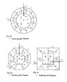
- a device for continuous wastewater treatment by means of a modified activation process according to the invention consists of the FIGS. 1a and 1b from a basin 1 with a bottom 2 and an outer shell 3.
- the basin 1 is divided by a partition 4 in an unventilated, vertical labyrinth 7 and a ventilated Bewritingraum 8.
- the secondary clarifier 9 is separated in the interior of the ventilated living space 8 by a jacket 5 of the secondary clarifier.
- the jacket 5 of the secondary clarifier 9 has the shape of a complete one turned and truncated cone or a beam ( Fig. 1 a) or the shape of a partially turned and truncated cone or beam ( Fig.
- the jacket 5 of the secondary clarifying chamber 9 with the bottom 2 of the basin 1 includes a minimum gradient of 60 °.
- the partition wall 4 and the jacket 5 of the secondary treatment chamber 9 extend from the floor 2 to above the level of the maximum level B, which is given by the level of the flood discharge system 29 of the floor 1.
- the partition wall 4 is located at the level of the minimum level A, which is given by the level of the outflow pipe 11, or on the ground level 2 of the basin 1, a passage opening 10.
- the jacket 5 of the secondary clarifier 9 is located on the ground level 2 of the basin 1, a passage opening 6.
- the non-aerated, vertically traversed labyrinth 7 is formed from a series of inner partitions 12 which extend from the bottom 2 to above the level of the maximum level B, which is given by the level of the spillway 29 of the soil 1.
- the individual successive partitions 12 have passage openings 13 alternately on the bottom plane 2 of the basin 1 and the plane of the minimum level A, which is given by the plane of the outflow line 11 from the basin 1.
- a flow controller 14 is disposed below the clear water level, as in Fig. 4 is shown.
- the flow regulator 14 is a hollow body, which consists of a lateral surface 15, an inflow opening 16 and an outflow shield 17, the inflow opening 16 being protected by a protective filter 18.
- the fixed permeability of the wastewater attack is the same as the fixed maximum flow in the discharge line from the device for wastewater treatment.
- the outflow opening 22 is connected to the throttle bore 19.
- the sewage water which is used for rinsing the protective filter.
- a flood relief system 29 is used, which is used for wastewater disposal for a larger flow than the specified maximum flow rate Q max . From the flood relief system 29, the sewage water flows into the outflow, in the secondary flow guide or in another basin, which, however, are not shown in the drawings.
- the retention space 24 is in the basin 1 between the level of the minimum level A, which is given by the plane of the outflow line 11 from the basin 1, and the level of the maximum level B, which is given by the level of the spillway 29 of the soil 1 delimited in the entire surface of the basin 1, therefore, so over the unvented, vertically traversed labyrinth 7, the ventilated Bevolraum 8 and the secondary treatment chamber 9, wherein the partition wall 4 together with the inner partitions 12 and the jacket 5 of the secondary treatment chamber 9 in the retention space 24th limit anaerobic, anoxic and oxic conditions as well as separation conditions for the activated sludge.
- the ventilation of the contents in the ventilated living space 8 is well known in the prior art.
- the source of compressed air which is not shown in the drawings, is also the source of compressed air for the mammoth pumps 26, 27, 28, the return of the activated sludge from the secondary clarifier 9 in the non-vented, vertically traversed labyrinth 7 and the recirculation Run the ventilated amenity space 8 in the non-vented, vertically traversed labyrinth 7 and the inner recirculation within the non-vented, vertically traversed labyrinth 7.
- the inflow of the raw sewage flows through the inflow line 25 into the unvented, vertical labyrinth 7.
- the activated sludge mixture which is formed by mixing the raw sewage with the recirculated activated sludge, flows through a series of inner partitions 12 and their changing passage opening 13 on the floor level. 2 of the basin 1 and in the plane of minimum level A, which is given by the plane of the outflow pipe 11 through.
- the alternating arrangement of the passage openings 13 at different heights in the partitions 12 in the flow direction establishes the conditions for an ideal and economical mixing of the contents in the non-aerated, vertical labyrinth 7, without the use of a mechanical mixer, in which anaerobic and anoxic conditions for produced the activated sludge.
- the activated sludge mixture flows out of the non-ventilated, vertical-flowed labyrinth 7 through a passage opening 10 in the partition wall 4 into the ventilated living space 8.
- oxigen conditions for the activated sludge are maintained by means of aeration.
- the activated sludge mixture flows into the secondary clarifier 9 through a passage opening 6 in the jacket 5 of the secondary clarifier 9 from.
- the function of the flow regulator 14 is that through the calibrated throttle bore 19, the sewage water can flow only in such a flow rate is less than or equal to the established maximum flow on the outflow line from the device to which the surface and the capacity of the final sedimentation chamber 9 are fixed , In the case of a higher flow, it comes in the entire tank 1 to a Water level elevation, from the water level plane A to the water level B by the throttling effect of the flow controller 14.
- the inner partitions 12, the partition 4 and the jacket 5 of the secondary clarifier 9 do not allow that there is an unlimited mutual mixing of the contents of the individual rooms, and therefore all wastewater treatment processes can take place undisturbed in the retention space 24.
- the throttle bore 19 and the passage openings 20 are protected from entrainment by a protective filter 18 which is rinsed cyclically with the treated wastewater.
- the flushing mechanism is based on the system that compressed air or pressurized water is driven through the opening 23 in the hollow body of the flow regulator 14 under the discharge shield 17.
- the compressed air or the pressurized water pumps the sewage water, which is located in the flow regulator 14, through the protective filter 18, and only when the pumped up sewage reaches the plane of the influence opening 21 of the passage openings 20, it starts to flow out through the throttle bore 19.
- a short-term recoil of the pressurized water or a mixture of compressed air and pressurized water produced in such a manner is sufficient for a complete cleaning of the protective filter 18, and manual cleaning is therefore no longer necessary.
- the material of the outer shell 3, the pelvic floor 2, the partition wall 4 and the inner partitions 12 of the basin 1 and the jacket 5 of the secondary treatment chamber 9 made of plastic construction wall elements, such as polyethylene (PE), polypropylene (PP) or hard polyvinyl chloride (HPVCs).
- plastic construction wall elements such as polyethylene (PE), polypropylene (PP) or hard polyvinyl chloride ( HPVCs).
- the basin 1 can also have the standard external dimensions of a container.
- the pools 1 can be divided into larger units be summarized once or successively, depending on the increase in the amount of wastewater produced.
- the material of the supporting walls, the outer shell 3, the pelvic floor 2 and the partition wall 4 can be made of wasserbauditionem concrete, the inner partitions 12 together with the jacket 5 of the Nachêtraums 9 plastic construction wall elements, such as polyethylene (PE), polypropylene ( (PP) or hard polyvinyl chloride (hPVC).
- PE polyethylene
- PP polypropylene
- hPVC hard polyvinyl chloride
- a device for a continuous wastewater treatment by means of modified activated sludge process consists of the Figures 2a, 2b and 2c from a basin 1 with a quadrangular floor plan, a floor 2 and an outer shell 3.
- the basin 1 is defined by a partition wall 4 in an unventilated, vertical labyrinth 7 and a ventilated Belocatingraum 8 with a passage opening 10 in the plane of the minimum level A, which is given by the plane of the outflow line 11 from the basin 1, or divided in the ground plane 2 of the basin 1
- the non-ventilated, vertically traversed labyrinth 7 is formed of a series of inner partitions 12 extending from the bottom 2 of the basin 1 to above Level of the maximum level B, which is given by the level of the spillway 29, and the passage openings 12 which alternately in the ground level 2 of the basin 1 and in the plane of the minimum level A, through the plane of the spout 11 in Flow direction is given, located and in a row ( Fig.
- the inner partitions 12 are arranged in a plurality of rows, they are divided from each other by a guide wall 30, wherein the flow direction on the left and right sides of the guide wall 30 is opposite, so that the principle can be followed Waste water progressively through all the inner partitions 12 runs and finally flows through the passage opening 13 into the ventilated Beppingraum 8.
- a device for continuous wastewater treatment by means of a modified activation method according to the invention consists of the Figures 3a, 3b and 3c from a tank 1 with a circular floor plan with a bottom 2 and an outer shell 3.
- the tank 1 may also have the shape of a polygon, such as a square or hexagon.
- the basin 1 with a circular or regular polygonal floor plan is formed by a concentrically arranged partition wall 4 into an unaerated, vertically traversed labyrinth 7 and a ventilated living space 8 with a passage opening 10 in the plane of the minimum level A, through the plane of the outflow line 11 is given to the basin 1, or divided in the ground plane 2 of the basin 1.
- the unaerated vertical through-flow labyrinth 7 is formed of radially arranged inner partitions 12 which extend from the bottom 2 to above the plane of the maximum level B, which is given by the level of the spillway 29, and those with passage openings 13, which alternate in the ground plane 2 of the basin 1 and in the plane of the minimum level A, which is given by the plane of the outflow pipe 11 in the flow direction, are located.
- a device according to the invention can be used in wastewater treatment from different, but especially from smaller sources, both in municipal and in industrial sources with a biodegradable Burden. Due to its flexibility, this device is particularly suitable for decentralized wastewater treatment solutions for smaller communities, schools, restaurants, hotels, pensions, greenfield sites, and the like. ⁇ . Suitable.
- the device is adaptable and can be gradually connected to larger units depending on the production increase of the effluents.
- the advantage of this device is low construction costs, as it allows the technical solution to deliver already finished, "packaged” or “container” sewage treatment plants, which require little assembly and construction work on the site, the quality of the sewage water also increased Requirements met from the point of view of wastewater quality. It is therefore possible to use these treatment plants also for the discharge of sewage waters into surface waters in sensitive areas where surface waters are likely to be subject to the effects of excessive fertilization, or for discharge into groundwater or reuse of sewage waters.
Landscapes
- Life Sciences & Earth Sciences (AREA)
- Water Supply & Treatment (AREA)
- Organic Chemistry (AREA)
- Hydrology & Water Resources (AREA)
- Engineering & Computer Science (AREA)
- Environmental & Geological Engineering (AREA)
- Biodiversity & Conservation Biology (AREA)
- Chemical & Material Sciences (AREA)
- Microbiology (AREA)
- Activated Sludge Processes (AREA)
- Purification Treatments By Anaerobic Or Anaerobic And Aerobic Bacteria Or Animals (AREA)
- Biological Treatment Of Waste Water (AREA)
- Physical Water Treatments (AREA)
- Water Treatment By Sorption (AREA)
- Electrical Discharge Machining, Electrochemical Machining, And Combined Machining (AREA)
Abstract
Description
Die Erfindung betrifft eine Vorrichtung zur kontinuierlichen, biologischen Abwasserreinigung aus kleineren Wasserverschmutzungsquellen mit modifiziertem Belebungsverfahren, in welcher in einem Becken ein Belebtraum mit raumisolierten, anaeroben, anoxischen und oxischen Zonen vereinigt wird und ein Nachklärraum mit einem Retentionsraum vereinigt wird, mit einem bestehenden Kreislauf zwischen den Zonen des Belebtraums und zwischen dem Belebtraum und dem Nachklärraum.The invention relates to a device for continuous, biological wastewater treatment from smaller sources of water pollution with a modified activation process, in which in a pool a living space with space-isolated, anaerobic, anoxic and oxic zones is combined and a secondary clarifier is combined with a retention space, with an existing circuit between the Zones of the living space and between the living space and the secondary room.
Für die Reinigung von Schmutzwasser aus Quellen, die nicht an das öffentliche Kanalisationssystem angeschlossen werden können, dienen kleinere Abwasserkläranlagen. Die Abwasserreinigung aus kleineren Wasserverschmutzungsquellen ist ein kompliziertes Problem, denn man ist mit der Problematik der beträchtlichen Variabilität der Abwasserdurchflüsse und der Variabilität der Wasserverschmutzung aus diesen kleineren Quellen konfrontiert. In relativ kleinen Abschnitten des Sammelkanals kommt es nicht zum Ausgleich der Abwassermenge und Abwassergüte. Daher muss man die einzelnen technischen Stufen des Prozesses der Abwasserreinigung (Ausgleichbecken, mechanische und biologische Reinigung und eventuelle Nachreinigung) so anpassen, dass sie nicht überfordert werden und damit die notwendige Verweildauer und die Flächenbelastung im Nachklärraum nicht überschritten werden. Wenn keine Bedingungen für den Ausgleich von Qualität und Quantität des Abwasserdurchflusses geschaffen worden sind, so müssen diese Stufen bedeutend überdimensioniert werden. Abwasserreinigungsanlagen sind auf den Durchschnittsdurchfluss von Q24 dimensioniert. Die stündliche Ungleichmäßigkeit des Durchflusses drückt ein weiterer dimensionierter Durchfluss aus, der stündliche Höchstdurchfluss Qmax.For the treatment of waste water from sources that can not be connected to the public sewer system, smaller sewage treatment plants are used. Wastewater treatment from smaller sources of water pollution is a complicated problem, because of the problems of considerable variability of wastewater flows and the variability of wastewater flows Water pollution faced by these smaller sources. In relatively small sections of the collecting channel, it does not balance the amount of sewage and sewage quality. Therefore, one must adapt the individual technical stages of the process of wastewater treatment (equalization tank, mechanical and biological cleaning and eventual subsequent cleaning) so that they are not overwhelmed and thus the necessary residence time and the surface load in the secondary clarification room are not exceeded. If no conditions have been established for balancing the quality and quantity of the wastewater flow, these stages must be significantly oversized. Wastewater treatment plants are dimensioned for the average flow rate of Q 24 . The hourly unevenness of the flow expresses another dimensioned flow, the maximum hourly flow Qmax.
In der Schrift
Auch in der Schrift
In der Schrift
In all diesen angeführten Lösungsmöglichkeiten wird der Ausgleich von Quantität und Qualität des verschmutzten Abwassers direkt im Belebtraum oder im Belebtraum und in den anderen Funktionsbecken oder in den Räumen der Kläranlage ohne ein speziell abgesondertes Ausgleichbecken erreicht. Der Ausgleich der Menge wird jedoch durch das Pumpen erzielt, womit aber erhöhte Kosten und eine erhöhte Störanfälligkeit verbunden sind.In all these solutions, the compensation of quantity and quality of the polluted wastewater directly in the living space or in the living space and in the other functional pools or in the rooms of the sewage treatment plant is achieved without a special separate balancing pool. The compensation of the amount is achieved by pumping, which, however, associated with increased costs and increased susceptibility.
Eine alternative Möglichkeit bei der Reinigung von Abwässern mit hoher Variabilität des Durchflusses und der Qualität ist die Verwendung von so genannten "sequencing batch"- oder "fed-batch"-Reaktoren (SBR Systeme). In der Schrift
In der Schrift
Bei dem Entwurf und bei der Realisierung der kleineren Abwasserreinigungsanlagen ist es notwendig, dass die kleineren Kläranlagen leicht transportable Fertigerzeugnisse oder an Ort und Stelle montierbar sind und sich mit einem Minimum an Bauarbeiten mit den Außenformen den Gegebenheiten der Anwendung oder der Landschaft anpassen, so dass sie anpassungsfähig sind und parallel mit dem Anstieg der produzierten Abwassermenge erweitert werden können. Kleinere Abwasserreinigungsanlagen mit einem integrierten Retentionsraum ermöglichen die Erfüllung all dieser Anforderungen nach dem gegenwärtigen Stand der Technik nicht gleichzeitig.In the design and implementation of the smaller wastewater treatment plants, it is necessary that the smaller wastewater treatment plants be easily transportable finished products or be assembled in situ and adapt to the conditions of the application or the landscape with a minimum of construction work with the outer shapes, so that they are adaptable and parallel with the Increase in the amount of wastewater produced can be extended. Smaller wastewater treatment plants with an integrated retention space do not allow the fulfillment of all these requirements in the current state of the art at the same time.
Die Aufgabe der Erfindung ist es, eine Vorrichtung für die Abwasserreinigung aus kleineren Wasserverschmutzungsquellen zu schaffen, die in einer kompakten Einheit mit der Möglichkeit der Form- und Änderbarkeit durch den Einsatz eines einfachen Betontraggerüsts und leichter Konstruktionswandelemente aus Kunststoff gefertigt werden kann. Dabei soll diese Vorrichtung in einer Funktionseinheit die Aufgabe des Ausgleichs des veränderlichen Durchflusses erfüllen und einen höchstmöglichen Wirkungsgrad der biologischen Reinigung unter Beseitigung von Stickstoff und Phosphor bei niedrigen Ansprüchen an die Pumpen- und Mischtechnik erreichen.The object of the invention is to provide a device for wastewater treatment from smaller sources of water pollution, which can be made in a compact unit with the possibility of formability and changeability by the use of a simple concrete support frame and lightweight construction wall elements made of plastic. This device should perform the task of balancing the variable flow in a functional unit and achieve the highest possible efficiency of biological purification with elimination of nitrogen and phosphorus with low demands on the pump and mixing technology.
Diese Aufgabe und die Mängel der bekannten Einrichtungen löst bzw. beseitigt im wesentlichen Maße die Vorrichtung zur kontinuierlichen, biologischen Abwasserreinigung mit einem modifizierten Belebungsverfahren, die in einem Becken einen Belebtraum mit unbelüfteten, anaeroben und anoxischen Zonen mit einer belüfteten, oxischen Zone und einen Nachklärraum mit einem Retentionsraum vereinigt, mit einer internen Rückführung zwischen den Zonen des Belebtraums und einer Rezirkulation des Rücklaufschlamms zwischen dem Belebtraum und Nachklärraum gemäß der Erfindung.This object and the deficiencies of the known devices solves or substantially eliminates the device for continuous biological wastewater treatment with a modified activated sludge process in a basin a vital space with unventilated, anaerobic and anoxic zones with a ventilated, oxic zone and a secondary clarifier a retention space combined with an internal return between the zones of the living space and a recirculation of the return sludge between the living space and secondary clarification according to the invention.
Das Wesen der Erfindung besteht darin, dass das Becken, das aus einem Boden und einem Außenmantel besteht, derart in ein unbelüftetes, vertikal durchflossenes Labyrinth, einen belüfteten Belebtraum, einen Nachklärraum und einen Retentionsraum aufgeteilt ist, dass das unbelüftete, vertikal durchflossene Labyrinth vom belüfteten Belebtraum durch eine Trennwand abgetrennt ist, die von dem Boden bis über die Ebene des maximalen Pegels (B) reicht, der durch die Ebene der Hochwasserentlastungsanlage gegeben ist, und die eine Durchlassöffnung entweder auf der Ebene des Beckens oder auf der Ebene der Auslassleitung aus dem Becken aufweist. Der Nachklärraum ist im Inneren des belüfteten Belebtraums durch einen Mantel begrenzt, der vom Boden bis über die Ebene des maximalen Pegels (B) reicht, der durch die Ebene der Hochwasserentlastungsanlage gegeben ist, und weist eine Durchlassöffnung auf der Bodenebene des Beckens auf. Der Retentionsraum befindet sich im Becken zwischen der Ebene des minimalen Pegels (A), die durch die aus dem Becken führende Ausflussleitung gegeben ist, und der Ebene des maximalen Wasserpegels (B), die durch die Ebene der Hochwasserentlastungsanlage gegeben ist, auf der ganzen Fläche des Beckens entlang über dem vertikal durchflossenen Labyrinth, dem belüfteten Belebtraum und dem Nachklärraum. Das vertikal durchflossene Labyrinth ist in Strömungsrichtung durch Trennwände geteilt, die vom Boden bis über die Ebene des maximalen Pegels (B) ragen, die durch die Ebene der Hochwasserentlastungsanlage gegeben ist und die ferner Durchlassöffnungen abwechselnd auf der Bodenebene des Beckens und auf der Ebene des minimalen Pegels (A) aufweisen, die durch die aus dem Becken führende Ausflussleitung gegeben ist, wobei im Nachklärraum auf der aus dem Becken führenden Ausflussleitung ein Durchflussregler mit einer kalibrierten Drosselöffnung angebracht ist.The essence of the invention is that the basin, which consists of a bottom and an outer shell, is divided into an unvented, vertically traversed labyrinth, a ventilated Belebtraum, a Nachklärraum and a retention space that the unventilated, vertically traversed labyrinth of the ventilated Living space is separated by a partition that extends from the floor to above the level of the maximum level (B) passing through the plane of the Flood relief system is given, and having a passage opening either at the level of the basin or at the level of the outlet pipe from the basin. The secondary clarifying room is confined inside the ventilated living space by a jacket extending from the floor to above the level of the maximum level (B) provided by the level of the spillway and has a passage opening at the bottom level of the basin. The retention space is located in the basin between the level of the minimum level (A), which is given by the effluent out of the basin outflow line, and the level of the maximum water level (B), which is given by the level of the spillway, on the whole area along the vertical labyrinth, the ventilated living space and the secondary sedimentation chamber. The vertically traversed labyrinth is divided in the direction of flow by dividing walls that protrude from the floor to above the level of the maximum level (B), which is given by the level of the spillway and the further passage openings alternately at the bottom level of the basin and at the level of the minimum Level (A), which is given by the purging out of the basin outflow line, wherein in the final sedimentation on the leading out of the basin outflow line, a flow regulator with a calibrated throttle opening is mounted.
Für einen wirkungsvollen Ausgleich eines schwankenden Durchflusses der Rohabwässer in die Einrichtung für Abwasserreinigung mit kontinuierlichem Zufluss und Ausfluss ist es wesentlich, dass es durch den Drosseleffekt des Durchflussreglers, der in der Ausflussleitung aus der Einrichtung gemäß der Erfindung angebracht ist, im Falle eines höheren Durchflusses als der dimensionierte auf der Ausflussleitung aus der Einrichtung zu einer Wasserspiegelhebung im ganzen Becken kommt, die von der minimalen Wasserspiegelebene (A), die der Ebene der Ausflussleitung entspricht, bis zur maximalen Wasserspiegelebene (B), die der Ebene der Hochwasserentlastungsanlage entspricht, wobei die inneren Trennwände in dem unbelüfteten, vertikal durchflossenen Labyrinth, die Trennwand zwischen dem belüfteten Belebtraum und dem unbelüfteten, vertikal durchflossenen Labyrinth und der Mantel des Nachklärraums nicht zulassen, dass es zu einer uneingeschränkten, gegenseitigen Vermischung der Inhalte der einzelnen Räume und Zonen kommt, da diese Trennwände und der Mantel bis über die Wasserspiegelebene, die durch die Hochwasserentlastungsanlage gegeben ist, reichen und so alle Abwasserreinigungsverfahren ungestört im Retentionsraum erfolgen können.For effectively balancing a fluctuating flow of raw sewage into the continuous inflow and outflow sewage treatment facility, it is essential that, in the case of a higher flow rate, than the throttling effect of the flow control device mounted in the outflow line of the device according to the invention the dimensioned on the effluent line from the facility comes to a water level elevation throughout the basin, ranging from the minimum water level (A), which corresponds to the level of the effluent line, to the maximum water level (B), which corresponds to the level of the spillway, with the inner Partitions in the unventilated, vertical labyrinth, the partition between the ventilated amenity space and the non - aerated vertical labyrinth and the mantle of the secondary clarifier do not allow the contents of the individual rooms and zones to be mixed unrestrictedly, since these partitions and the jacket extend above the level of the water level through the Flood relief system is given rich, and so all wastewater treatment process can be done undisturbed in the retention room.
Wegen der Anpassung an den sukzessiven Anstieg der Abwasserproduktion ist es vorteilhaft, wenn die Vorrichtung für die kontinuierliche, biologische Abwasserreinigung mit einem modifizierten Belebungsverfahren gemäß der Erfindung arbeiten kann, wobei die Vorrichtung aus einem Becken mit einem viereckigem Grundriss, mit einem Boden und einem Außenmantel bestehen kann und wobei in dem unbelüfteten, vertikal durchflossenen Labyrinth innere Trennwände platziert sind, die von dem Boden des Beckens bis über die Ebene des maximalen Pegels (B), der durch die Ebene der Hochwasserentlastungsanlage gegeben ist, ragen und die mit Durchlassöffnungen versehen sind, die sich abwechselnd auf der Bodenebene des Beckens und auf der Ebene des minimalen Pegels (A), die durch die Ebene der Ausflussleitung in Strömungsrichtung gegeben ist, befinden und die in einer oder mehreren Reihen angeordnet sind, wobei die Reihen durch eine Leitwand voneinander getrennt sind. Gemäß der Erfindung ist es möglich, mehrere Becken parallel in größere Einheiten zusammenzufassen und somit eine fortschreitende Kapazitätssteigerung der Abwasserreinigungsanlagen je nach Produktionssteigerung des rohen Abwassers zu gewährleisten.Because of adapting to the successive increase in wastewater production, it is advantageous if the continuous biological wastewater treatment apparatus can operate with a modified activation process according to the invention, the apparatus consisting of a basin with a quadrangular layout, with a bottom and an outer shell and wherein inner partitions are located in the non-aerated, vertically-traversed labyrinth, projecting from the bottom of the basin to above the level of the maximum level (B) provided by the plane of the spillway, which are provided with ports are alternately located at the bottom plane of the basin and at the level of the minimum level (A) provided by the plane of the outflow conduit in the direction of flow and which are arranged in one or more rows, the rows being separated by a baffle. According to the invention, it is possible to combine several basins in parallel into larger units and thus to ensure a progressive increase in capacity of the wastewater treatment plants depending on the production increase of the raw wastewater.
Die Vorrichtung zur kontinuierlichen Abwasserreinigung mit einem modifizierten Belebungsverfahren gemäß der Erfindung kann zweckmäßig in einem Becken mit einem kreisförmigen Grundriss mit einem Boden und einem Außenmantel ausgeführt werden.The device for continuous wastewater treatment with a modified activated sludge process according to the invention may conveniently be carried out in a basin having a circular floor plan with a bottom and an outer shell.
Das Becken der Vorrichtung gemäß der Erfindung kann auch eine vieleckige Form aufweisen, beispielsweise ein Quadrat oder Sechseck, wobei das Becken durch eine konzentrisch angeordnete Trennwand mit einem kreisförmigen oder vieleckigen Grundriss in einen unbelüfteten Belebtraum und ein belüftetes, vertikal durchflossenes Labyrinth mit einer Durchlassöffnung auf der Ebene des minimalen Pegels (A), die durch die Ebene der Ausflussleitung aus dem Becken gegeben ist, oder auf der Bodenebene des Beckens aufgeteilt ist. In dem unbelüfteten, vertikal durchflossenen Labyrinth befinden sich radial angeordnete innere Trennwände, die vom Boden bis über die Ebene des maximalen Pegels (B), der durch die Ebene der Hochwasserentlastungsanlage des Bodens gegeben ist, ragen und die Durchlassöffnungen aufweisen, die sich abwechselnd auf der Bodenebene des Beckens und auf der Ebene des minimalen Pegels (A), die durch die Ebene der Ausflussleitung in Strömungsrichtung gegeben ist, befinden.The basin of the device according to the invention may also have a polygonal shape, for example a square or hexagon, the basin being defined by a concentrically arranged partition wall with a circular or polygonal floor plan in an unventilated vital space and a ventilated vertical labyrinth with a passage opening on the Level of the minimum level (A), which is given by the level of the outflow pipe from the basin, or is divided at the floor level of the basin. In the unaerated, vertically traversed labyrinth there are radially disposed inner partitions that protrude from the bottom to the level of the maximum level (B), which is given by the level of the spillway of the soil, and have the passage openings that alternate on the Floor level of the basin and at the level of the minimum level (A), which is given by the plane of the outflow line in the flow direction, are.
Die Vorrichtung gemäß der Erfindung wird vorteilhaft bei monolithischen oder vorgefertigten Betonbecken aus wasserbaufähigem Beton gefertigt, wobei das Becken einen kreisförmigen, quadratischen oder vieleckigen Grundriss aufweist, der Boden, der Außenmantel, die Trennwand zwischen dem unbelüfteten, vertikal durchflossenen Labyrinth und dem belüfteten Belebtraum und die Leitwand zwischen den Reihen von Trennwänden aus wasserbaufähigem Beton hergestellt sind und der Mantel des Nachklärraums aus Konstruktionswandelementen aus Kunststoff, wie beispielsweise aus Polyethylen (PE), Polypropylen (PP) oder Hartpolyvinylchlorid (hPVC), hergestellt ist. Gemäß der Erfindung ist es möglich, mehrere Becken parallel in größere Einheiten zusammenzufassen und somit eine fortschreitende Kapazitätssteigerung der Abwasserreinigungsanlagen je nach Produktionssteigerung des Rohabwassers zu gewährleisten.The device according to the invention is advantageously produced in monolithic or prefabricated concrete basins made of water-buildable concrete, the basin having a circular, square or polygonal plan, the bottom, the outer shell, the partition between the non-vented, vertically traversed labyrinth and the ventilated Belebtraum and the Baffle between the rows of partitions are made of wasserbaufähigem concrete and the jacket of Nachklärraums made of plastic construction wall elements, such as polyethylene (PE), polypropylene (PP) or hard polyvinyl chloride (hPVC), is made. According to the invention, it is possible to combine several basins in parallel into larger units and thus to ensure a progressive increase in capacity of the wastewater treatment plants depending on the increase in production of raw sewage.
Die Vorrichtung gemäß der Erfindung wird vorteilhaft bei Becken mit einem kreisförmigen, quadratischen oder vieleckigen Grundriss eingesetzt, wobei der Boden, der Außenmantel, die Trennwand zwischen dem unbelüfteten, vertikal durchflossenen Labyrinth und dem belüfteten Belebtraum und die Leitwand zwischen den Reihen von Trennwänden aus Konstruktionswandelementen aus Kunststoff, wie beispielsweise aus Polyethylen (PE), Polypropylen (PP) oder Hartpolyvinylchlorid (hPVC) hergestellt werden. Gemäß der Erfindung ist es möglich, mehrere Becken parallel in größere Einheiten zusammenzufassen und somit eine fortschreitende Kapazitätssteigerung der Abwasserreinigungsanlagen je nach Produktionssteigerung des Rohabwassers zu gewährleisten.The device according to the invention is advantageously used in basins with a circular, square or polygonal floor plan, wherein the floor, the outer shell, the partition wall between the non-aerated, vertically traversed labyrinth and the ventilated Belebtraum and the baffle between the rows of partitions of construction wall elements Plastic, such as polyethylene (PE), polypropylene (PP) or hard polyvinyl chloride (hPVC) are produced. According to the invention, it is possible to combine several basins in parallel into larger units and thus to ensure a progressive increase in capacity of the wastewater treatment plants depending on the increase in production of raw sewage.
Für den Einfachbetrieb des Durchflussreglers ist es nicht von Bedeutung, diesen zu warten, da die Drosselbohrung und die Durchlassöffnungen durch einen Schutzfilter, der zyklisch mit dem gereinigten Abwasser abgespült wird, vor Verschlämmung geschützt sind. Der Spülmechanismus beruht auf dem System, dass durch die Öffnung in einem Hohlkörper des Durchflussreglers unter einer Ausflussabschirmung Druckluft bzw. Druckwasser das Klärwasser, das sich im Strömungsregler im Raum zwischen dem Mantel des Durchflussreglers und der Überströmleitung im Inneren des Durchflussreglers befindet, durch den Schutzfilter hochpumpt. Erst dann, wenn das hochgepumpte Klärwasser die Höhe der Einflussöffnung der Überströmleitung erreicht hat, beginnt das Druckwasser bzw. die Druckluft durch die Drosselbohrung auszuströmen. Ein auf diese Weise hergestellter kurzzeitiger Rückstoß des Druckwassers oder eines Gemisches aus Druckluft und Druckwasser ist für eine vollkommene Reinigung des Schutzfilters ausreichend, und eine manuelle Reinigung ist daher nicht mehr nötig.For the simple operation of the flow regulator, it is not important to maintain it because the restrictor bore and ports are protected from entrainment by a protective filter which is rinsed cyclically with the treated wastewater. The flushing mechanism is based on the system that through the opening in a hollow body of the flow regulator under a discharge shield compressed air or pressurized water, the clarified water, which is located in the flow controller in the space between the flow regulator jacket and the overflow line inside the flow controller, through the protective filter , Only then, when the pumped up sewage water has reached the height of the influence opening of the overflow line, the pressurized water or compressed air begins to flow out through the throttle bore. A short-term recoil of the pressurized water or a mixture of compressed air and pressurized water produced in this way is sufficient for a complete cleaning of the protective filter, and manual cleaning is therefore no longer necessary.
Bei der technischen Lösung der Mängel bei kleineren Abwasserreinigungsanlagen nach dem bisherigem Stand der Technik wurde gemäß der Erfindung eine Vorrichtung zur Abwasserreinigung aus kleineren Wasserverschmutzungsquellen entworfen, die in einer kompakten Einheit mit der Möglichkeit der Form- und Änderbarkeit durch den Einsatz eines einfachen Betontraggerüsts und leichter Konstruktionswandelemente aus Kunststoff gefertigt werden kann. Dabei soll die Vorrichtung in einer Funktionseinheit die Aufgabe des Ausgleichs des veränderlichen Durchflusses erfüllen und einen höchstmöglichen Wirkungsgrad der biologischen Reinigung unter Beseitigung von Stickstoff und Phosphor und unter niedrigen Ansprüchen an die Pumpen- und Mischtechnik erreichen.In the technical solution of the deficiencies in smaller wastewater treatment plants according to the prior art, according to the invention, a device for wastewater treatment from smaller water pollution sources designed to be manufactured in a compact unit with the possibility of formability and changeability through the use of a simple concrete support frame and lightweight construction wall elements made of plastic. The device should perform the task of balancing the variable flow in a functional unit and achieve the highest possible efficiency of biological purification with elimination of nitrogen and phosphorus and low demands on the pump and mixing technology.
Die Erfindung wird nun anhand von Ausführungsbeispielen näher erläutert.The invention will now be explained in more detail with reference to exemplary embodiments.
Es zeigen:
- Figuren 1a, 1b
- eine Vorrichtung für die Abwasserreinigung gemäß der Erfindung,
Figuren 2a, 2b, 2c- eine Vorrichtung für die Abwasserreinigung mit einem viereckigen Grundriss,
- Figuren 3a, 3b, 3c
- eine Vorrichtung für die Abwasserreinigung mit einem kreisförmigen, quadratisches oder vieleckigen Grundriss und
- Fig. 4
- einen Durchflussregler.
- FIGS. 1a, 1b
- a device for wastewater treatment according to the invention,
- FIGS. 2a, 2b, 2c
- a device for sewage treatment with a quadrangular floor plan,
- FIGS. 3a, 3b, 3c
- a device for sewage treatment with a circular, square or polygonal floor plan and
- Fig. 4
- a flow regulator.
Eine Vorrichtung zur kontinuierlichen Abwasserreinigung mittels eines modifizierten Belebungsverfahrens gemäß der Erfindung besteht nach den
Der Zufluss des Rohabwassers mündet durch die Zuflussleitung 25 in das unbelüftete, vertikal durchflossene Labyrinth 7. Das Belebtschlammgemisch, das durch das Mischen des Rohabwassers mit dem rezirkulierten Belebtschlamm entsteht, fließt durch eine Reihe von inneren Trennwänden 12 und deren wechselnde Durchlassöffnung 13 auf der Bodenebene 2 des Beckens 1 und in der Ebene des minimalen Pegels A, die durch die Ebene der Ausflussleitung 11 gegeben ist, hindurch. Die abwechselnde Anordnung der Durchlassöffnungen 13 in unterschiedlichen Höhen in den Trennwänden 12 in Strömungsrichtung stellt die Bedingungen für eine ideale und sparsame Vermischung des Inhalts in dem unbelüfteten, vertikal durchflossenen Labyrinth 7 her, ohne die Verwendung eines mechanischen Mischwerks, in dem anaerobe und anoxische Bedingungen für den Belebtschlamm hergestellt werden. Aus dem unbelüfteten, vertikal durchflossenen Labyrinth 7 fließt das Belebtschlammgemisch durch eine Durchlassöffnung 10 in der Trennwand 4 in den belüfteten Belebtraum 8 ab. Im belüfteten Belebtraum 8 werden mittels der Belüftung oxische Bedingungen für den Belebtschlamm aufrechterhalten. Aus dem belüfteten Belebtraum 8 fließt das Belebtschlammgemisch in den Nachklärraum 9 durch eine Durchlassöffnung 6 im Mantel 5 des Nachklärraums 9 ab. Im Nachklärraum 9 kommt es durch die Wirkung der Schwerkraft zur Ablagerung des Belebtschlamms, wobei der Belebtschlamm aus dem Nachklärraum 9 in Form vom Rücklaufschlamm mit einer Mammutpumpe 27 in das unbelüftete, vertikal durchflossene Labyrinth 7 abgesaugt wird und das Klärwasser durch den Durchflussregler 14 und die Auslassleitung 11 aus dem Becken 1 der Wasserreinigungsanlage abfließt. Das Klärwasser fließt in den Strömungsregler 14 durch ein Schutzfilter 18 an der Einflussöffnung 16 des Durchflussreglers 14 hinein. Im Inneren des Durchflussreglers 14 befindet sich nach dem Schutzfilter 18 eine Einflussöffnung 21 der Überströmleitung 20, welche an ihrem anderen Ende in eine Drosselbohrung 19 der Ausflussabschirmung 17 mündet. Hinter der Ausflussabschirmung 17 fließt das geklärte Abwasser frei durch die Auslassleitung 11 aus dem Becken 1 ab. Die Funktion des Durchflussreglers 14 besteht darin, dass durch die kalibrierte Drosselbohrung 19 das Klärwasser nur in solcher Durchflussmenge abfließen kann, die kleiner oder gleich dem festgelegten Höchstdurchfluss auf der Ausflussleitung aus der Einrichtung ist, auf den die Fläche und das Fassungsvermögen des Nachklärraums 9 festgelegt sind. Im Falle eines höheren Durchflusses kommt es im ganzen Becken 1 zu einer Wasserspiegelhebung, aus der Wasserspiegelebene A bis zur Wasserspiegelebene B durch den Drosseleffekt des Durchflussreglers 14. Die inneren Trennwände 12, die Trennwand 4 und der Mantel 5 des Nachklärraums 9 lassen nicht zu, dass es zu einer uneingeschränkten gegenseitigen Vermischung der Inhalte der einzelnen Räume kommt, und deshalb können alle Abwasserreinigungsverfahren ungestört im Retentionsraum 24 erfolgen.The inflow of the raw sewage flows through the
Die Drosselbohrung 19 und die Durchlassöffnungen 20 sind durch einen Schutzfilter 18, der zyklisch mit dem gereinigten Abwasser abgespült wird, vor Verschlämmung geschützt. Der Spülmechanismus beruht auf dem System, dass durch die Öffnung 23 in dem Hohlkörper des Durchflussreglers 14 unter der Ausflussabschirmung 17 Druckluft bzw. Druckwasser eingetrieben wird. Die Druckluft oder das Druckwasser pumpt das Klärwasser, das sich im Durchflussregler 14 befindet, durch das Schutzfilter 18 hoch, und erst wenn das hochgepumpte Klärwasser die Ebene der Einflussöffnung 21 der Durchlassöffnungen 20 erreicht, beginnt es durch die Drosselbohrung 19 auszuströmen. Ein auf solche Weise hergestellter kurzzeitiger Rückstoß des Druckwassers oder eines Gemisches aus Druckluft und Druckwasser ist für eine vollkommene Reinigung des Schutzfilters 18 ausreichend, und eine manuelle Reinigung ist daher nicht mehr nötig.The throttle bore 19 and the passage openings 20 are protected from entrainment by a
Praktischerweise wird das Material des Außenmantels 3, des Beckenbodens 2, der Trennwand 4 und der inneren Trennwände 12 des Beckens 1 und des Mantels 5 des Nachklärraums 9 aus Konstruktionswandelementen aus Kunststoff hergestellt, beispielsweise aus Polyäthylen (PE), Polypropylen (PP) oder Hartpolyvinylchlorid (hPVC).Conveniently, the material of the
Zur Transporterleichterung kann das Becken 1 auch die Standardaußenmaße eines Containers haben. Am Standort können die Becken 1 in größere Einheiten auf einmal oder sukzessiv zusammengefasst werden, je nach Anstieg der produzierten Abwassermenge.To facilitate transport, the
Das Material der Tragwände, des Außenmantels 3, des Beckenbodens 2 und der Trennwand 4 können aus wasserbaufähigem Beton hergestellt werden, die inneren Trennwände 12 zusammen mit dem Mantel 5 des Nachklärraums 9 aus Konstruktionswandelementen aus Kunststoff, wie beispielsweise aus Polyäthylen (PE), Polypropylen ((PP) oder Hartpolyvinylchlorid (hPVC).The material of the supporting walls, the
Eine Vorrichtung für eine kontinuierliche Abwasserreinigung mittels modifiziertem Belebungsverfahren gemäß der Erfindung besteht nach den
Eine Vorrichtung für eine kontinuierliche Abwasserreinigung mittels eines modifizierten Belebungsverfahren gemäß der Erfindung besteht nach den
Eine Vorrichtung gemäß der Erfindung kann bei der Abwasserreinigung aus unterschiedlichen, vor allem aber aus kleineren Quellen verwendet werden, sowohl bei kommunalen wie auch bei industriellen Quellen mit einer biologisch abbaubaren Belastung. Aufgrund ihrer Flexibilität ist diese Vorrichtung besonders für dezentrale Lösungen der Abwasserreinigung für kleinere Gemeinden, Schulen, Restaurants, Hotels, Pensionen, auf grüner Wiese gebaute Industrieanlagen u. ä. geeignet. Die Vorrichtung ist anpassungsfähig und kann schrittweise zu größeren Einheiten je nach dem Produktionsanstieg der Abwässer verbunden werden. Der Vorteil dieser Vorrichtung sind niedrige Baukosten, da es die technische Lösung ermöglicht, schon fertige, "eingepackte" oder "Container"-Abwasserkläranlagen zu liefern, die nur geringe Montage- und Bauarbeiten auf dem Anlagenort erfordern, wobei die Qualität des Klärwassers auch die erhöhten Anforderungen aus der Sicht der Abwasserqualität erfüllt. Deshalb ist es möglich, diese Kläranlagen auch für den Auslass der Klärwässer in die Oberflächengewässer in empfindlichen Gebieten, in denen die Oberflächengewässer dem Einfluss einer übermäßigen Düngung zu unterliegen drohen, oder für den Auslass in das Grundwasser oder auch bei der Wiederverwendung der Klärwässer zu verwenden.A device according to the invention can be used in wastewater treatment from different, but especially from smaller sources, both in municipal and in industrial sources with a biodegradable Burden. Due to its flexibility, this device is particularly suitable for decentralized wastewater treatment solutions for smaller communities, schools, restaurants, hotels, pensions, greenfield sites, and the like. Ä. Suitable. The device is adaptable and can be gradually connected to larger units depending on the production increase of the effluents. The advantage of this device is low construction costs, as it allows the technical solution to deliver already finished, "packaged" or "container" sewage treatment plants, which require little assembly and construction work on the site, the quality of the sewage water also increased Requirements met from the point of view of wastewater quality. It is therefore possible to use these treatment plants also for the discharge of sewage waters into surface waters in sensitive areas where surface waters are likely to be subject to the effects of excessive fertilization, or for discharge into groundwater or reuse of sewage waters.
Claims (7)
- Waste water purifying device by a modified activated sludge process with continuous inflow and outflow, combining in one tank the activated-sludge chamber with compartmentalized anaerobic and anoxic zones with vertical through-flow and an aerated oxic zone, secondary sedimentation chamber and retention chamber, with internal recirculation between the zones of the activated-sludge chambers and recirculation of return sludge between the activated-sludge chamber and secondary sedimentation chamber, characterized in that
the tank (1) with a bottom (2) and sidewall (3) is partitioned into a non-aerated vertically through-flown labyrinth (7), an aerated activated-sludge chamber (8), secondary sedimentation chamber (9) and retention chamber (24), wherein the non-aerated vertically through-flown labyrinth (7) is separated from the aerated activated-sludge chamber (8) by a partition wall (4) extending from bottom (2) up to a height over the maximum level B given by the level of a safety overflow (29), and having a passage opening (10) at the level of the bottom (2) of the tank (1) or at the height of minimum level A given by the level of outlet conduit (11) from the tank (1), the secondary sedimentation chamber (9) is formed inside the aerated activated sludge chamber (8) by shell (5) extending from the bottom (2) up to a height over the maximum level B given by the level of safety overflow (29), and having a passage opening (6) at the level of bottom (2) of the tank (1), and the retention chamber (24) is formed in the tank (1) between the height of the minimum level A given by the level of outlet conduit (11) from the tank (1), and the height of the maximum level B given by the level of safety overflow (29) throughout the whole surface area of the tank (1) over the non-aerated vertically through-flown labyrinth (7), the aerated activated-sludge chamber (8) and the secondary sedimentation chamber (9), whereby a flow regulator (14), having a calibrated throttling opening (19) is arranged in the secondary sedimentation chamber (9) on the outlet conduit (11) from the tank (1). - Device according to claim 1,
characterized in that
the non-aerated vertically through-flown labyrinth (7) is formed by a series of inner partition walls (12) in the direction of advancing flow, extending from bottom (2) up to a height over the maximum level B given by the level of safety overflow (29), and having passage openings (13) alternately at the level of the bottom (2) of the tank (1) and at the height of the minimum level A given by the level of outlet conduit (11) from the tank (1). - Device according to claims 1 and 2,
characterized in that
the tank (1) has sidewall (3) of a circular ground plan or polygonal ground plan with at least four edges, and the partition wall (4) between the non-aerated vertically through-flown labyrinth (7) and the aerated activated-sludge chamber (8) is concentrically arranged with a circular ground plan or polygonal ground plan with at least four edges, wherein the non-aerated vertically through-flown labyrinth (7) is formed by a series of at least six radially arranged inner partition walls (12) in the direction of advancing flow. - Device according to claims 1 to 3,
characterized in that
the tank (1) has sidewall (3) of a rectangular ground plan, and the non-aerated vertically through-flown labyrinth (7) is formed by at least two parallel rows of inner partition walls (12), separated by a guiding wall (30), with a series of inner partition walls (12) extending from the bottom (2) of the tank up to a height over the maximum level B given by the level of safety overflow (29), and having passage openings (13) alternately at the level of the bottom (2) of the tank (1) and at the level of the minimum level A given by the level of the outlet conduit (11) in the direction of advancing flow, with guiding wall (30) extending from the bottom (2) of the the tank up to a height over the maximum level B given by the level of the safety overflow (29). - Device according to claims 1 to 4,
characterized in that
the material of the bottom (2), sidewall (3) and partition wall (4) between the non-aerated vertically through-flown labyrinth (7) and the aerated activated sludge chamber (8) and of the guiding wall (30) is watertight concrete and/or plastic constructional wall element, and the material of inner partition walls (12) and shell (5) is plastic constructional wall element. - Device according to claims 1 to 5,
characterized in that
the screen (18) for coarse impurities at the inlet opening ( (16) of the flow regulator (14) is backwashed by treated water accumulated inside of the flow regulator (14) between the shell (15) of the flow regulator (14) and passage conduit (20) by periodical blowing of pressurized fluid medium into the flow regulator (14). - Device according to claim 6,
characterized in that
the pressurized fluid medium is compressed air or pressurized water.
Priority Applications (1)
| Application Number | Priority Date | Filing Date | Title |
|---|---|---|---|
| PL06776841T PL1919833T3 (en) | 2005-08-22 | 2006-08-15 | Waste water purifying device |
Applications Claiming Priority (2)
| Application Number | Priority Date | Filing Date | Title |
|---|---|---|---|
| SK50672005 | 2005-08-22 | ||
| PCT/EP2006/008031 WO2007022899A1 (en) | 2005-08-22 | 2006-08-15 | Waste water purifying device |
Publications (2)
| Publication Number | Publication Date |
|---|---|
| EP1919833A1 EP1919833A1 (en) | 2008-05-14 |
| EP1919833B1 true EP1919833B1 (en) | 2010-06-30 |
Family
ID=37192486
Family Applications (1)
| Application Number | Title | Priority Date | Filing Date |
|---|---|---|---|
| EP06776841A Active EP1919833B1 (en) | 2005-08-22 | 2006-08-15 | Waste water purifying device |
Country Status (8)
| Country | Link |
|---|---|
| EP (1) | EP1919833B1 (en) |
| AT (1) | ATE472514T1 (en) |
| AU (1) | AU2006284174B2 (en) |
| DE (1) | DE502006007333D1 (en) |
| HU (1) | HUE009445T2 (en) |
| PL (1) | PL1919833T3 (en) |
| UA (1) | UA86173C2 (en) |
| WO (1) | WO2007022899A1 (en) |
Families Citing this family (10)
| Publication number | Priority date | Publication date | Assignee | Title |
|---|---|---|---|---|
| CN101734791B (en) * | 2008-11-26 | 2011-07-27 | 孙光志 | Method for treating biological sewage |
| EP2766313B1 (en) | 2011-09-08 | 2016-07-27 | Schuster, Péter | Small installation for biological wastewater treatment with improved efficiency |
| CN103877775B (en) | 2012-12-20 | 2017-03-01 | 奥加尼卡有限责任公司 | For liquid handling in particular for disc type effluent filter equipment filter plate |
| CN103979753A (en) * | 2014-04-14 | 2014-08-13 | 居国文 | Gas stripping type sludge lifting device |
| CN109422422A (en) * | 2017-08-24 | 2019-03-05 | 张建军 | A kind of sewage disposal device and sewage water treatment method |
| CN109665622A (en) * | 2019-02-25 | 2019-04-23 | 华新方 | A kind of environmental protection sewage-treatment plant |
| CN113106937B (en) * | 2021-04-09 | 2022-09-30 | 华北水利水电大学 | River is with water purification collection husky system |
| CN113818947B (en) * | 2021-10-26 | 2022-12-02 | 广船国际有限公司 | Desulfurization system circulating water tank and ship |
| CN114524584A (en) * | 2022-02-10 | 2022-05-24 | 湖北兴为春科技有限公司 | FBR-F integrated sewage treatment equipment |
| CN115246676A (en) * | 2022-07-01 | 2022-10-28 | 北京新城禹潞环保科技有限责任公司 | Gravity type small sewage treatment equipment |
Family Cites Families (7)
| Publication number | Priority date | Publication date | Assignee | Title |
|---|---|---|---|---|
| US3886065A (en) | 1972-03-10 | 1975-05-27 | Kappe Associates Inc | Waste water treatment plant with balanced load |
| US4505813A (en) | 1982-06-14 | 1985-03-19 | Norwalk Wastewater Equipment Company | Wastewater treatment plant |
| DE4307288A1 (en) | 1993-03-09 | 1994-09-15 | Oekoservice Ges Fuer Umweltana | Process for biological wastewater treatment with integrated buffering |
| US5989428A (en) | 1996-06-21 | 1999-11-23 | Goronszy; Mervyn Charles | Controlling wastewater treatment by monitoring oxygen utilization rates |
| DE19916381C2 (en) | 1999-03-31 | 2002-07-18 | Tobias Breithaupt | Controlled small wastewater treatment plant for biological-chemical wastewater treatment for wastewater with a buffer tank that compares the hydraulic load |
| US6210578B1 (en) * | 1999-10-29 | 2001-04-03 | Universidad Nacional Autonoma De Mexico | Residual water treatment microplant for small flows |
| WO2002012133A1 (en) * | 2000-08-03 | 2002-02-14 | Bioclar, A.S. | Activated sludge method and device for the treatment of effluent with nitrogen and phosphorus removal |
-
2006
- 2006-08-15 AU AU2006284174A patent/AU2006284174B2/en active Active
- 2006-08-15 DE DE502006007333T patent/DE502006007333D1/en active Active
- 2006-08-15 AT AT06776841T patent/ATE472514T1/en active
- 2006-08-15 UA UAA200803495A patent/UA86173C2/en unknown
- 2006-08-15 WO PCT/EP2006/008031 patent/WO2007022899A1/en active Application Filing
- 2006-08-15 EP EP06776841A patent/EP1919833B1/en active Active
- 2006-08-15 PL PL06776841T patent/PL1919833T3/en unknown
- 2006-08-15 HU HUE06776841 patent/HUE009445T2/en unknown
Also Published As
| Publication number | Publication date |
|---|---|
| PL1919833T3 (en) | 2010-11-30 |
| WO2007022899A1 (en) | 2007-03-01 |
| HUE009445T2 (en) | 2007-03-01 |
| AU2006284174B2 (en) | 2010-06-03 |
| UA86173C2 (en) | 2009-03-25 |
| ATE472514T1 (en) | 2010-07-15 |
| EP1919833A1 (en) | 2008-05-14 |
| DE502006007333D1 (en) | 2010-08-12 |
| AU2006284174A1 (en) | 2007-03-01 |
Similar Documents
| Publication | Publication Date | Title |
|---|---|---|
| EP1919833B1 (en) | Waste water purifying device | |
| AT396682B (en) | WASTEWATER PLANT | |
| EP0595359B1 (en) | Method and device for wastewater purification | |
| DE102006019741A1 (en) | Water recirculation plant for pisciculture and fish feeding, includes water distribution assembly, flooded bioreactors for microbiological water nitrification, sedimentation filters, fish basins, pump chamber with water supply plant | |
| EP2456723A1 (en) | Wastewater treatment plant and method for treating wastewater, and wastewater treatment system | |
| DE10010109A1 (en) | Compact base filter reactor for sedimentation and biological purification of waste waters | |
| EP0688304B1 (en) | Process for biological water purification with integrated buffering | |
| DE102009039316A1 (en) | Wastewater treatment plant and process for wastewater treatment | |
| DE19838692A1 (en) | Waste water treatment plant for small remote settlement has distributor shaft to low-cost modular reed basins reducing capital and operating costs | |
| EP1714946A2 (en) | Apparatus and process for the biological treatment of waste water | |
| EP0749942A2 (en) | Installation for the biological treatment of waste water | |
| EP2100856B1 (en) | Method for microbiological treatment of water | |
| EP1132348B1 (en) | Installation and process for purification of waste water | |
| DE4122804C2 (en) | Sewage treatment plant | |
| EP1588987B1 (en) | Water treatment plant having concentric basins | |
| DE19951194A1 (en) | Multi-purpose shaft, small sewage treatment plant and wastewater treatment process | |
| DE102014103652A1 (en) | Small wastewater treatment plant for biological treatment of wastewater | |
| DE19842884C9 (en) | PROCESS FOR BIOLOGICAL AND BIOLOGICAL-CHEMICAL TREATMENT OF WASTE WATER WITH INTEGRATED SLUDGE SEPARATOR | |
| DE19529567C2 (en) | External module for upgrading a wastewater treatment plant as well as a wastewater treatment plant equipped with the module | |
| DE4239184C1 (en) | Biological sewage phosphate removal - has initial stripper centrally in the stripper basin with separate zones for sludge to move in opposite directions | |
| DE2149552A1 (en) | Process and system for cleaning waste water | |
| DE202014102520U1 (en) | Equipment for the production of a water treatment plant | |
| DE102005032123A1 (en) | Process and plant for biological wastewater treatment in a circulation zone reactor | |
| DE29915706U1 (en) | Biological wastewater treatment facility | |
| WO2019101948A1 (en) | Waste water purifying system and method for purifying waste water |
Legal Events
| Date | Code | Title | Description |
|---|---|---|---|
| PUAI | Public reference made under article 153(3) epc to a published international application that has entered the european phase |
Free format text: ORIGINAL CODE: 0009012 |
|
| 17P | Request for examination filed |
Effective date: 20080320 |
|
| AK | Designated contracting states |
Kind code of ref document: A1 Designated state(s): AT BE BG CH CY CZ DE DK EE ES FI FR GB GR HU IE IS IT LI LT LU LV MC NL PL PT RO SE SI SK TR |
|
| AX | Request for extension of the european patent |
Extension state: HR RS |
|
| 17Q | First examination report despatched |
Effective date: 20081015 |
|
| GRAP | Despatch of communication of intention to grant a patent |
Free format text: ORIGINAL CODE: EPIDOSNIGR1 |
|
| RAX | Requested extension states of the european patent have changed |
Extension state: RS Payment date: 20080320 Extension state: HR Payment date: 20080320 |
|
| GRAF | Information related to payment of grant fee modified |
Free format text: ORIGINAL CODE: EPIDOSCIGR3 |
|
| GRAS | Grant fee paid |
Free format text: ORIGINAL CODE: EPIDOSNIGR3 |
|
| GRAA | (expected) grant |
Free format text: ORIGINAL CODE: 0009210 |
|
| AK | Designated contracting states |
Kind code of ref document: B1 Designated state(s): AT BE BG CH CY CZ DE DK EE ES FI FR GB GR HU IE IS IT LI LT LU LV MC NL PL PT RO SE SI SK TR |
|
| AX | Request for extension of the european patent |
Extension state: HR RS |
|
| REG | Reference to a national code |
Ref country code: GB Ref legal event code: FG4D Ref country code: CH Ref legal event code: EP |
|
| REG | Reference to a national code |
Ref country code: IE Ref legal event code: FG4D Free format text: LANGUAGE OF EP DOCUMENT: GERMAN |
|
| REF | Corresponds to: |
Ref document number: 502006007333 Country of ref document: DE Date of ref document: 20100812 Kind code of ref document: P |
|
| REG | Reference to a national code |
Ref country code: RO Ref legal event code: EPE |
|
| REG | Reference to a national code |
Ref country code: NL Ref legal event code: VDEP Effective date: 20100630 |
|
| PG25 | Lapsed in a contracting state [announced via postgrant information from national office to epo] |
Ref country code: LT Free format text: LAPSE BECAUSE OF FAILURE TO SUBMIT A TRANSLATION OF THE DESCRIPTION OR TO PAY THE FEE WITHIN THE PRESCRIBED TIME-LIMIT Effective date: 20100630 Ref country code: SE Free format text: LAPSE BECAUSE OF FAILURE TO SUBMIT A TRANSLATION OF THE DESCRIPTION OR TO PAY THE FEE WITHIN THE PRESCRIBED TIME-LIMIT Effective date: 20100630 |
|
| LTIE | Lt: invalidation of european patent or patent extension |
Effective date: 20100630 |
|
| PG25 | Lapsed in a contracting state [announced via postgrant information from national office to epo] |
Ref country code: SI Free format text: LAPSE BECAUSE OF FAILURE TO SUBMIT A TRANSLATION OF THE DESCRIPTION OR TO PAY THE FEE WITHIN THE PRESCRIBED TIME-LIMIT Effective date: 20100630 Ref country code: FI Free format text: LAPSE BECAUSE OF FAILURE TO SUBMIT A TRANSLATION OF THE DESCRIPTION OR TO PAY THE FEE WITHIN THE PRESCRIBED TIME-LIMIT Effective date: 20100630 Ref country code: LV Free format text: LAPSE BECAUSE OF FAILURE TO SUBMIT A TRANSLATION OF THE DESCRIPTION OR TO PAY THE FEE WITHIN THE PRESCRIBED TIME-LIMIT Effective date: 20100630 |
|
| REG | Reference to a national code |
Ref country code: PL Ref legal event code: T3 |
|
| PG25 | Lapsed in a contracting state [announced via postgrant information from national office to epo] |
Ref country code: GR Free format text: LAPSE BECAUSE OF FAILURE TO SUBMIT A TRANSLATION OF THE DESCRIPTION OR TO PAY THE FEE WITHIN THE PRESCRIBED TIME-LIMIT Effective date: 20101001 |
|
| PG25 | Lapsed in a contracting state [announced via postgrant information from national office to epo] |
Ref country code: NL Free format text: LAPSE BECAUSE OF FAILURE TO SUBMIT A TRANSLATION OF THE DESCRIPTION OR TO PAY THE FEE WITHIN THE PRESCRIBED TIME-LIMIT Effective date: 20100630 Ref country code: EE Free format text: LAPSE BECAUSE OF FAILURE TO SUBMIT A TRANSLATION OF THE DESCRIPTION OR TO PAY THE FEE WITHIN THE PRESCRIBED TIME-LIMIT Effective date: 20100630 |
|
| REG | Reference to a national code |
Ref country code: IE Ref legal event code: FD4D |
|
| BERE | Be: lapsed |
Owner name: CSEFALVAY, JURAJ Effective date: 20100831 Owner name: PENZES, LADISLAV Effective date: 20100831 |
|
| PG25 | Lapsed in a contracting state [announced via postgrant information from national office to epo] |
Ref country code: CY Free format text: LAPSE BECAUSE OF FAILURE TO SUBMIT A TRANSLATION OF THE DESCRIPTION OR TO PAY THE FEE WITHIN THE PRESCRIBED TIME-LIMIT Effective date: 20100630 Ref country code: SK Free format text: LAPSE BECAUSE OF FAILURE TO SUBMIT A TRANSLATION OF THE DESCRIPTION OR TO PAY THE FEE WITHIN THE PRESCRIBED TIME-LIMIT Effective date: 20100630 Ref country code: PT Free format text: LAPSE BECAUSE OF FAILURE TO SUBMIT A TRANSLATION OF THE DESCRIPTION OR TO PAY THE FEE WITHIN THE PRESCRIBED TIME-LIMIT Effective date: 20101102 Ref country code: IS Free format text: LAPSE BECAUSE OF FAILURE TO SUBMIT A TRANSLATION OF THE DESCRIPTION OR TO PAY THE FEE WITHIN THE PRESCRIBED TIME-LIMIT Effective date: 20101030 |
|
| REG | Reference to a national code |
Ref country code: HU Ref legal event code: AG4A Ref document number: E009445 Country of ref document: HU |
|
| PG25 | Lapsed in a contracting state [announced via postgrant information from national office to epo] |
Ref country code: MC Free format text: LAPSE BECAUSE OF NON-PAYMENT OF DUE FEES Effective date: 20100831 Ref country code: IT Free format text: LAPSE BECAUSE OF FAILURE TO SUBMIT A TRANSLATION OF THE DESCRIPTION OR TO PAY THE FEE WITHIN THE PRESCRIBED TIME-LIMIT Effective date: 20100630 |
|
| REG | Reference to a national code |
Ref country code: CH Ref legal event code: PL |
|
| PG25 | Lapsed in a contracting state [announced via postgrant information from national office to epo] |
Ref country code: LI Free format text: LAPSE BECAUSE OF NON-PAYMENT OF DUE FEES Effective date: 20100831 Ref country code: CH Free format text: LAPSE BECAUSE OF NON-PAYMENT OF DUE FEES Effective date: 20100831 Ref country code: DK Free format text: LAPSE BECAUSE OF FAILURE TO SUBMIT A TRANSLATION OF THE DESCRIPTION OR TO PAY THE FEE WITHIN THE PRESCRIBED TIME-LIMIT Effective date: 20100630 Ref country code: IE Free format text: LAPSE BECAUSE OF FAILURE TO SUBMIT A TRANSLATION OF THE DESCRIPTION OR TO PAY THE FEE WITHIN THE PRESCRIBED TIME-LIMIT Effective date: 20100630 |
|
| PLBE | No opposition filed within time limit |
Free format text: ORIGINAL CODE: 0009261 |
|
| STAA | Information on the status of an ep patent application or granted ep patent |
Free format text: STATUS: NO OPPOSITION FILED WITHIN TIME LIMIT |
|
| 26N | No opposition filed |
Effective date: 20110331 |
|
| PG25 | Lapsed in a contracting state [announced via postgrant information from national office to epo] |
Ref country code: ES Free format text: LAPSE BECAUSE OF FAILURE TO SUBMIT A TRANSLATION OF THE DESCRIPTION OR TO PAY THE FEE WITHIN THE PRESCRIBED TIME-LIMIT Effective date: 20101011 |
|
| REG | Reference to a national code |
Ref country code: DE Ref legal event code: R097 Ref document number: 502006007333 Country of ref document: DE Effective date: 20110330 |
|
| PG25 | Lapsed in a contracting state [announced via postgrant information from national office to epo] |
Ref country code: BE Free format text: LAPSE BECAUSE OF NON-PAYMENT OF DUE FEES Effective date: 20100831 |
|
| PG25 | Lapsed in a contracting state [announced via postgrant information from national office to epo] |
Ref country code: BG Free format text: LAPSE BECAUSE OF FAILURE TO SUBMIT A TRANSLATION OF THE DESCRIPTION OR TO PAY THE FEE WITHIN THE PRESCRIBED TIME-LIMIT Effective date: 20100630 Ref country code: LU Free format text: LAPSE BECAUSE OF NON-PAYMENT OF DUE FEES Effective date: 20100815 |
|
| PG25 | Lapsed in a contracting state [announced via postgrant information from national office to epo] |
Ref country code: TR Free format text: LAPSE BECAUSE OF FAILURE TO SUBMIT A TRANSLATION OF THE DESCRIPTION OR TO PAY THE FEE WITHIN THE PRESCRIBED TIME-LIMIT Effective date: 20100630 |
|
| REG | Reference to a national code |
Ref country code: AT Ref legal event code: MM01 Ref document number: 472514 Country of ref document: AT Kind code of ref document: T Effective date: 20110815 |
|
| PG25 | Lapsed in a contracting state [announced via postgrant information from national office to epo] |
Ref country code: AT Free format text: LAPSE BECAUSE OF NON-PAYMENT OF DUE FEES Effective date: 20110815 |
|
| REG | Reference to a national code |
Ref country code: DE Ref legal event code: R081 Ref document number: 502006007333 Country of ref document: DE Owner name: PENZES, LADISLAV, SK Free format text: FORMER OWNER: LADISLAV PENZES,JURAJ CSEFALVAY, , SK Effective date: 20130314 Ref country code: DE Ref legal event code: R081 Ref document number: 502006007333 Country of ref document: DE Owner name: CSEFALVAY, JURAJ, SK Free format text: FORMER OWNER: LADISLAV PENZES,JURAJ CSEFALVAY, , SK Effective date: 20130314 Ref country code: DE Ref legal event code: R081 Ref document number: 502006007333 Country of ref document: DE Owner name: AQUATEC VFL S.R.O., SK Free format text: FORMER OWNER: LADISLAV PENZES,JURAJ CSEFALVAY, , SK Effective date: 20130314 Ref country code: DE Ref legal event code: R081 Ref document number: 502006007333 Country of ref document: DE Owner name: AQUATEC VFL S.R.O., SK Free format text: FORMER OWNERS: PENZES, LADISLAV, BAC, SK; CSEFALVAY, JURAJ, TOMASOV, SK Effective date: 20130314 Ref country code: DE Ref legal event code: R081 Ref document number: 502006007333 Country of ref document: DE Owner name: CSEFALVAY, JURAJ, SK Free format text: FORMER OWNERS: PENZES, LADISLAV, BAC, SK; CSEFALVAY, JURAJ, TOMASOV, SK Effective date: 20130314 Ref country code: DE Ref legal event code: R081 Ref document number: 502006007333 Country of ref document: DE Owner name: PENZES, LADISLAV, SK Free format text: FORMER OWNERS: PENZES, LADISLAV, BAC, SK; CSEFALVAY, JURAJ, TOMASOV, SK Effective date: 20130314 |
|
| REG | Reference to a national code |
Ref country code: FR Ref legal event code: TQ Owner name: CSEFALVAY, JURAJ, SK Effective date: 20130528 Ref country code: FR Ref legal event code: TQ Owner name: AQUATEC VFL S.R.O., SK Effective date: 20130528 Ref country code: FR Ref legal event code: TQ Owner name: PENZES, LADISLAV, SK Effective date: 20130528 |
|
| PG25 | Lapsed in a contracting state [announced via postgrant information from national office to epo] |
Ref country code: BG Free format text: LAPSE BECAUSE OF FAILURE TO SUBMIT A TRANSLATION OF THE DESCRIPTION OR TO PAY THE FEE WITHIN THE PRESCRIBED TIME-LIMIT Effective date: 20100930 |
|
| REG | Reference to a national code |
Ref country code: HU Ref legal event code: GB9C Owner name: LADISLAV PENZES, SK Free format text: FORMER OWNER(S): PENZES, LADISLAV, SK; CSEFALVAY, JURAJ, SK Ref country code: HU Ref legal event code: GB9C Owner name: JURAJ CSEFALVAY, SK Free format text: FORMER OWNER(S): PENZES, LADISLAV, SK; CSEFALVAY, JURAJ, SK Ref country code: HU Ref legal event code: GB9C Owner name: AQUATEC VFL S.R.O., SK Free format text: FORMER OWNER(S): PENZES, LADISLAV, SK; CSEFALVAY, JURAJ, SK Ref country code: HU Ref legal event code: FH1C Free format text: FORMER REPRESENTATIVE(S): PINTZ ES TARSAI SZABADALMI, VEDJEGY ES JOGI IRODA, HU Representative=s name: INTERINNO SZABADALMI IRODA, HU |
|
| REG | Reference to a national code |
Ref country code: FR Ref legal event code: ST Effective date: 20160429 |
|
| REG | Reference to a national code |
Ref country code: FR Ref legal event code: PLFP Year of fee payment: 11 |
|
| PG25 | Lapsed in a contracting state [announced via postgrant information from national office to epo] |
Ref country code: FR Free format text: LAPSE BECAUSE OF NON-PAYMENT OF DUE FEES Effective date: 20150831 |
|
| REG | Reference to a national code |
Ref country code: FR Ref legal event code: RN Effective date: 20160927 |
|
| REG | Reference to a national code |
Ref country code: FR Ref legal event code: FC Effective date: 20161011 |
|
| PG25 | Lapsed in a contracting state [announced via postgrant information from national office to epo] |
Ref country code: FR Free format text: LAPSE BECAUSE OF NON-PAYMENT OF DUE FEES Effective date: 20150831 |
|
| PGRI | Patent reinstated in contracting state [announced from national office to epo] |
Ref country code: FR Effective date: 20161011 |
|
| REG | Reference to a national code |
Ref country code: GB Ref legal event code: 732E Free format text: REGISTERED BETWEEN 20170216 AND 20170222 |
|
| REG | Reference to a national code |
Ref country code: FR Ref legal event code: PLFP Year of fee payment: 12 |
|
| REG | Reference to a national code |
Ref country code: FR Ref legal event code: PLFP Year of fee payment: 13 |
|
| PGFP | Annual fee paid to national office [announced via postgrant information from national office to epo] |
Ref country code: RO Payment date: 20230731 Year of fee payment: 18 Ref country code: GB Payment date: 20230802 Year of fee payment: 18 Ref country code: CZ Payment date: 20230803 Year of fee payment: 18 |
|
| PGFP | Annual fee paid to national office [announced via postgrant information from national office to epo] |
Ref country code: PL Payment date: 20230807 Year of fee payment: 18 Ref country code: HU Payment date: 20230803 Year of fee payment: 18 Ref country code: FR Payment date: 20230802 Year of fee payment: 18 Ref country code: DE Payment date: 20230803 Year of fee payment: 18 |