EP1919111A1 - Systeme et appareil de communication sans fil - Google Patents
Systeme et appareil de communication sans fil Download PDFInfo
- Publication number
- EP1919111A1 EP1919111A1 EP05774910A EP05774910A EP1919111A1 EP 1919111 A1 EP1919111 A1 EP 1919111A1 EP 05774910 A EP05774910 A EP 05774910A EP 05774910 A EP05774910 A EP 05774910A EP 1919111 A1 EP1919111 A1 EP 1919111A1
- Authority
- EP
- European Patent Office
- Prior art keywords
- delay time
- multipath delay
- communication apparatus
- data
- guard
- Prior art date
- Legal status (The legal status is an assumption and is not a legal conclusion. Google has not performed a legal analysis and makes no representation as to the accuracy of the status listed.)
- Withdrawn
Links
Images


Classifications
-
- H—ELECTRICITY
- H04—ELECTRIC COMMUNICATION TECHNIQUE
- H04B—TRANSMISSION
- H04B1/00—Details of transmission systems, not covered by a single one of groups H04B3/00 - H04B13/00; Details of transmission systems not characterised by the medium used for transmission
- H04B1/69—Spread spectrum techniques
- H04B1/713—Spread spectrum techniques using frequency hopping
- H04B1/715—Interference-related aspects
-
- H—ELECTRICITY
- H04—ELECTRIC COMMUNICATION TECHNIQUE
- H04L—TRANSMISSION OF DIGITAL INFORMATION, e.g. TELEGRAPHIC COMMUNICATION
- H04L27/00—Modulated-carrier systems
- H04L27/26—Systems using multi-frequency codes
-
- H—ELECTRICITY
- H04—ELECTRIC COMMUNICATION TECHNIQUE
- H04J—MULTIPLEX COMMUNICATION
- H04J9/00—Multiplex systems in which each channel is represented by a different type of modulation of the carrier
-
- H—ELECTRICITY
- H04—ELECTRIC COMMUNICATION TECHNIQUE
- H04L—TRANSMISSION OF DIGITAL INFORMATION, e.g. TELEGRAPHIC COMMUNICATION
- H04L25/00—Baseband systems
- H04L25/02—Details ; arrangements for supplying electrical power along data transmission lines
- H04L25/03—Shaping networks in transmitter or receiver, e.g. adaptive shaping networks
- H04L25/03006—Arrangements for removing intersymbol interference
- H04L25/03159—Arrangements for removing intersymbol interference operating in the frequency domain
-
- H—ELECTRICITY
- H04—ELECTRIC COMMUNICATION TECHNIQUE
- H04L—TRANSMISSION OF DIGITAL INFORMATION, e.g. TELEGRAPHIC COMMUNICATION
- H04L27/00—Modulated-carrier systems
- H04L27/26—Systems using multi-frequency codes
- H04L27/2601—Multicarrier modulation systems
- H04L27/2602—Signal structure
- H04L27/26025—Numerology, i.e. varying one or more of symbol duration, subcarrier spacing, Fourier transform size, sampling rate or down-clocking
-
- H—ELECTRICITY
- H04—ELECTRIC COMMUNICATION TECHNIQUE
- H04L—TRANSMISSION OF DIGITAL INFORMATION, e.g. TELEGRAPHIC COMMUNICATION
- H04L5/00—Arrangements affording multiple use of the transmission path
- H04L5/003—Arrangements for allocating sub-channels of the transmission path
- H04L5/0048—Allocation of pilot signals, i.e. of signals known to the receiver
-
- H—ELECTRICITY
- H04—ELECTRIC COMMUNICATION TECHNIQUE
- H04L—TRANSMISSION OF DIGITAL INFORMATION, e.g. TELEGRAPHIC COMMUNICATION
- H04L25/00—Baseband systems
- H04L25/02—Details ; arrangements for supplying electrical power along data transmission lines
- H04L25/03—Shaping networks in transmitter or receiver, e.g. adaptive shaping networks
- H04L25/03006—Arrangements for removing intersymbol interference
- H04L2025/0335—Arrangements for removing intersymbol interference characterised by the type of transmission
- H04L2025/03375—Passband transmission
- H04L2025/03414—Multicarrier
-
- H—ELECTRICITY
- H04—ELECTRIC COMMUNICATION TECHNIQUE
- H04L—TRANSMISSION OF DIGITAL INFORMATION, e.g. TELEGRAPHIC COMMUNICATION
- H04L27/00—Modulated-carrier systems
- H04L27/26—Systems using multi-frequency codes
- H04L27/2601—Multicarrier modulation systems
- H04L27/2602—Signal structure
- H04L27/2605—Symbol extensions, e.g. Zero Tail, Unique Word [UW]
-
- H—ELECTRICITY
- H04—ELECTRIC COMMUNICATION TECHNIQUE
- H04L—TRANSMISSION OF DIGITAL INFORMATION, e.g. TELEGRAPHIC COMMUNICATION
- H04L5/00—Arrangements affording multiple use of the transmission path
- H04L5/0001—Arrangements for dividing the transmission path
- H04L5/0003—Two-dimensional division
- H04L5/0005—Time-frequency
- H04L5/0007—Time-frequency the frequencies being orthogonal, e.g. OFDM(A), DMT
-
- H—ELECTRICITY
- H04—ELECTRIC COMMUNICATION TECHNIQUE
- H04L—TRANSMISSION OF DIGITAL INFORMATION, e.g. TELEGRAPHIC COMMUNICATION
- H04L5/00—Arrangements affording multiple use of the transmission path
- H04L5/0001—Arrangements for dividing the transmission path
- H04L5/0014—Three-dimensional division
- H04L5/0016—Time-frequency-code
- H04L5/0021—Time-frequency-code in which codes are applied as a frequency-domain sequences, e.g. MC-CDMA
-
- H—ELECTRICITY
- H04—ELECTRIC COMMUNICATION TECHNIQUE
- H04L—TRANSMISSION OF DIGITAL INFORMATION, e.g. TELEGRAPHIC COMMUNICATION
- H04L5/00—Arrangements affording multiple use of the transmission path
- H04L5/003—Arrangements for allocating sub-channels of the transmission path
- H04L5/0037—Inter-user or inter-terminal allocation
- H04L5/0039—Frequency-contiguous, i.e. with no allocation of frequencies for one user or terminal between the frequencies allocated to another
Definitions
- the present invention relates to a radio communication system employing a multi-carrier modulation/demodulation method, and more particularly, to a communication apparatus capable of working in a communication environment in which a multipath delay time varies.
- a multi-carrier modulation/demodulation method as typified by an OFDM (orthogonal frequency division multiplexing) method and a DMT (discrete multi-tone) method.
- the multi-carrier modulation/demodulation method is used, for example, in a wireless LAN or an ADSL, and is a method of transmitting a plurality of frequencies by allocating the frequencies to orthogonal carriers.
- a guard interval or a cyclic prefix is used to eliminate an effect of a delayed wave.(GB) caused by, for example, a condition of a transmission path between a transmitter and a receiver.
- the receiver eliminates the effect of the delayed wave in the guard interval, for example, by applying an FFT to an OFDM symbol from which the guard interval is removed, and thereby demodulating data.
- a delay time is lengthened.
- the delay time is shortened.
- a length of an appropriate guard interval depends on a location of the terminal or an environment.
- an OFDM communication system and an OFDM communication method disclosed in patent document 1.
- a guard interval length which is used to be a fixed length before, is adaptively controlled depending on a multipath delay time, and thereby achieving the maximum transmitting efficiency.
- Patent document 1 Japanese Patent Application Laid-Open No. 2002-374223
- Fig. 9 is a schematic diagram of an example of a signal in a case where a variable guard interval is used. Specifically, it shows a signal in a case where the multipath delay time varies.
- a horizontal axis represents a time (t)
- an upper portion of a vertical axis represents a multipath delay time (a normalized max delay time) (Lc)
- Lc normalized max delay time
- a lower portion of the vertical axis represents a sub-carrier in a frequency direction.
- a degree of the multipath delay time varies in such a way that "medium ⁇ small ⁇ large" with time.
- the signal is composed of "Sym” including data information and the guard interval "GI” (a guard interval length "L GI "), satisfying "L C ⁇ L GI ", and "L GI " varies with “L C ".
- GI guard interval length
- the present invention has been achieved to solve the above problems in the conventional technology, and an object of the present invention is to provide a communication apparatus capable of coping with a variation of the multipath delay time with a simple hardware configuration.
- a radio communication system employs a multi-carrier modulation/demodulation method.
- a data-transmission-side communication apparatus includes a mapping unit that executes a mapping process with respect to a data sub-carrier based on a multipath delay time in a transmission path obtained by a predetermined estimating process, and a guard-band adding unit that varies an amount of a guard band to be added to a signal on the data sub-carrier depending on information on the guard band obtained based on the multipath delay time.
- a data-reception-side communication apparatus includes an equalizing unit that suppresses a multipath exceeding a guard interval (including a case where the guard interval is not added) based on the information on the guard band obtained based on the multipath delay time, and a demapping unit that executes a demapping process with respect to an equalized signal based on the multipath delay time.
- an amount of a guard band is configured to vary depending on a multipath delay time in a transmission path. Therefore, it is possible to cope with a variation of the multipath delay time with a simple hardware configuration without changing a symbol length.
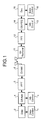
- Fig. 1 is a schematic diagram of an example of a configuration of a radio communication system according to the present invention, i.e., an example of configurations of a data-transmission-side communication apparatus and a data-reception-side communication apparatus.
- the transmission-side communication apparatus (corresponding to a modulator) includes a Data-control module 1, a Data module 2, a GB-control module 3, a GB-add module 4, an IFFT module 5, and a GB-add module 6.
- the reception-side communication apparatus (corresponding to a demodulator) includes a GI-removal module 11, an FFT module 12, a GB-control module 13, a GB-FEQ module 14, a Data-control module 15, and a Dec module 16.
- the Data-control modules 1 and 15 instruct a position and an amount of a data sub-carrier.
- the Data module 2 encodes data to be transmitted, and maps the encoded data in the data sub-carrier located on a frequency domain in accordance with an instruction from the Data-control module 1.
- the GB-control modules 3 and 13 instruct a type, a position, and an amount of a guard band (GB).
- the GB-add module 4 adds the guard band to the data sub-carrier output from the Data-control module 1 in accordance with an instruction from the GB-control module 3.
- the IFFT module 5 converts a frequency-domain signal into a time-domain signal.
- the GI-add module 6 adds a guard interval to the time-domain signal.
- the GI-removal module 11 removes the guard interval from the received signal.
- the FFT module 12 converts the time-domain signal into a frequency-domain signal.
- the GB-FEQ module 14 performs a frequency equalization by using the guard band in accordance with an instruction from the GB-control module 13 to suppress a delayed wave exceeding the guard interval.
- the Dec module 16 demodulates the data sub-carrier (a demapping process) in accordance with an instruction from the Data-control module 15, and performs a decoding process including an error correction.
- the Data-control module 1 and the GB-control module 3 control a data sub-carrier and a guard band depending on a multipath delay time in a transmission path.
- the multipath delay time in the transmission path is estimated by the reception side based on a received signal.
- the multipath delay time in the transmission path is estimated by the transmission side, and the estimated multipath delay time is fed back to the reception side.
- the data sub-carrier and the guard band are controlled based on parameters for estimating communication qualities such as a frame error rate and a least-squares distance.
- guard band is a generic name for a sub-carrier which transmitting content is known to the reception side, and corresponds to a null carrier that does not transmit data, a pilot carrier that transmits fixed data, and the like.
- the GB-FEQ is a frequency equalizing apparatus that suppresses a multipath exceeding the guard interval by using the guard band; for example, the one described in A. Okazaki et al., "Frequency Domain Equalization of Multipath Signals with Insufficient Guard Interval", Proceedings of the IEICE (Institute of Electronics, Information and Communication Engineers) General Conference B-5-21, 2005 can be used.
- the GB-FEQ module 14 can extend the suppressible multipath delay time by increasing an amount of the guard band.
- the radio communication system includes the modulator and the demodulator as shown in Fig. 1 .
- the GB-control module 3 instructs a type and a position of the guard band, and an amount of the guard band appropriate for the multipath delay time in the transmission path, and the GB-add module adds the guard band in accordance with an instruction from the GB-control module 3.
- the GB-control module 13 instructs a type, a position, and an amount of the guard band
- the GB-FEQ module 14 realizes a frequency equalization by using the guard band in accordance with an instruction from the GB-control module 13.
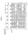
- Fig. 2 is a schematic diagram of an example of a signal to which the guard band is added. For example, it shows a signal in a case where the multipath delay time varies.
- a horizontal axis represents a time (t)
- an upper portion of a vertical axis represents the multipath delay time (LC)
- a lower portion of the vertical axis represents a sub-carrier in a frequency direction.
- a degree of the multipath delay time varies in such a way that "medium ⁇ small ⁇ large" with time.
- the signal is composed of "Sym” including data information, the guard interval “GI” (a guard interval length “L GI “), and the guard band “GB” (the number of the guard bands “L GB “).
- the guard band is inserted depending on the multipath delay time "L C " so as to meet a condition of "L C ⁇ L GI +L GB ".
- the guard band is not inserted when a degree of the multipath delay time is "small”, and one number of the guard band is inserted when a degree of the multipath delay time is "medium”, and then two numbers of the guard bands are inserted when a degree of the multipath delay time is "large”.
- an amount of the guard band is configured to vary depending on the multipath delay time in the transmission path. Therefore, it is possible to cope with a variation of the multipath delay time with a simple hardware configuration without changing a symbol length.
- the multipath can be suppressed with the guard band added by the GB-add module 4.
- an OFDMA (orthogonal frequency division multiplex access) method is applied to the above-mentioned process of "varying an amount of the guard band depending on the multipath delay time", which is a characteristic process in the first embodiment.
- a system configuration in the present embodiment is identical to that is in the first embodiment as shown in Fig. 1 .
- a process different from that is performed in the first embodiment is explained below.
- Fig. 3 is a schematic diagram of an example of a signal to which the guard band is added. For example, it shows a signal in a case where the multipath delay time varies.
- data is frequency-division multiplexed into eight numbers of sub-carriers, and the user 1 and the user 2 respectively have the multipath delay time different from each other.
- a sufficient amount of the guard band is inserted.
- the maximum amount of the multipath delay time L c varies in such a way that "large ⁇ medium ⁇ large", so that the number of the guard bands L GB to be added varies in such a way that "two guard bands ⁇ one guard band ⁇ two guard bands" in accordance with the variation of the maximum amount of the multipath delay time L c .
- an amount of the guard band is configured to vary depending on the maximum amounts of the multipath delay time for each of multiple users. Consequently, it is possible to cope with a variation of the multipath delay time with a simple hardware configuration without changing a symbol length.
- an OFCDM (orthogonal frequency and code division multiplexing) method or a MC-CDMA (multi-carrier - code division multiple access) method is applied to the above-mentioned process of "varying an amount of the guard band depending on the multipath delay time", which is a characteristic process in the first embodiment.
- a system configuration in the present embodiment is identical to that is in the first embodiment as shown in Fig. 1 .
- a process different from that is performed in the first embodiment is explained below.
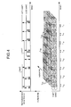
- Fig. 4 is a schematic diagram of an example of a signal to which the guard band is added. For example, it shows a signal in a case where the multipath delay time varies.
- data is code-division multiplexed into eight numbers of sub-carriers, and the user 1 and the user 2 respectively have the multipath delay time different from each other.
- a lower portion of a vertical axis represents the number of multiplexing
- a depth represents the sub-carriers in a frequency direction.
- a sufficient amount of the guard band is inserted.
- the maximum amount of the multipath delay time L c varies in such a way that "large ⁇ medium ⁇ large", so that the number of the guard bands L GB to be added varies in such a way that "two guard bands ⁇ one guard band ⁇ two guard bands" in accordance with the variation of the maximum amount of the multipath delay time L c .
- an amount of the guard band is configured to vary depending on the maximum amounts of the multipath delay time for each of multiple users. Consequently, it is possible to cope with a variation of the multipath delay time with a simple hardware configuration without changing a symbol length.
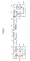
- Fig. 5 is a schematic diagram of an example of a configuration of a radio communication system according to the present invention, i.e., an example of configurations of a data-transmission-side communication apparatus and a data-reception-side communication apparatus.
- the transmission-side communication apparatus (corresponding to a modulator) includes a Data-control module 1a, a GB-control module 3a, a MCS-control module 7a, the GB-add module 4, the IFFT module 5, and the GI-add module 6.
- the reception-side communication apparatus (corresponding to a demodulator) includes a GB-control module 13a, a Data-control module 15a, a MCS-control module 17a, the FFT module 12, the GB-FEQ module 14, and the Dec module 16.
- the portions identical to those in Fig. 1 for the first embodiment are denoted with the same reference numerals, and the description of those portions is omitted. A process different from that is performed in the first embodiment is explained below.
- the MCS-control modules 7a and 17a are modules for instructing a MCS (modulation and coding scheme), and give an instruction on a parameter to the Data-control modules 1a and 15a and the GB-control modules 3a and 13a based on the MCS that is set up in advance.
- each of the MCS-control modules controls the Data-control module and the GB-control module depending on the multipath delay time in the transmission path.
- the multipath delay time in the transmission path is estimated by the reception side based on a received signal.
- the multipath delay time in the transmission path is estimated by the transmission side, and the estimated multipath delay time is fed back to the reception side. Then, by using such characteristics that a communication quality decreases in accordance with an increase of the multipath delay in the transmission path, the data sub-carrier and the guard band are indirectly controlled based on parameters for estimating communication qualities such as a frame error rate and a least-squares distance.
- Fig. 6 is a schematic diagram of an example of the MCS used in the MCS-control module.
- it is controlled in such a way that the number of the sub-carriers is reduced, and the number of the guard bands increases.
- the MCS is created focused on only the number of the guard bands to make it simplified.
- it is also possible to combine a modulation and coding scheme composed of a modulation scheme and an encoding rate.
- the radio communication system includes the modulator and the demodulator as shown in Fig. 5 .
- the MCS-control modules 7a and 17a in the modulator and the demodulator respectively select the MCS adaptively depending on the multipath delay time in the transmission path. Then, based on the coding scheme, each of the MCS-control modules instructs the number of the sub-carriers to be used to the Data-control module and the number of the guard bands to be used to the GB-control module.
- the radio communication system to improve the delay-tolerant performance, it is configured to reduce the number of the sub-carriers and to increase the number of the guard bands. Consequently, in a case where the multipath delay time in the transmission path increases, the radio communication system according to the fourth embodiment can achieve to improve a tolerance to the multipath delay time as a trade-off for a degradation of an information transmission rate due to the reduction of the number of the sub-carriers, in addition to the same effect as that is in the first embodiment.
- Fig. 7 is a schematic diagram of an example of a configuration of a radio communication system according to the present invention, i.e., an example of configurations of a data-transmission-side communication apparatus and a data-reception-side communication apparatus.
- the transmission-side communication apparatus (corresponding to a modulator) includes a Rate-control module 8b, the GB-control module 3a, the GB-add module 4, the IFFT module 5, the GI-add module 6, and the MCS-control module 7a.
- the reception-side communication apparatus (corresponding to a demodulator) includes a Rate-control module 18b, the FFT module 12, the GB-control module 13a, the GB-FEQ module 14, the Dec module 16, and the MCS-control module 17a.
- the portions identical to those in Fig. 5 for the fourth embodiment are denoted with the same reference numerals, and the description of those portions is omitted. A process different from that is performed in the fifth embodiment is explained below.
- the MCS-control modules 7a and 17a give an instruction on a parameter to the Rate-control modules 8b and 18b and the GB-control modules 3a and 13a based on the MCS that is set up in advance. Then, the Rate-control modules 8b and 18b instruct an encoding rate to be used in the Data module 2 and the Dec module 16 based on the instruction.
- Fig. 8 is a schematic diagram of an example of the MCS used in the MCS-control module.
- it is configured to increase the encoding rate and the number of the guard bands.
- the communication apparatus when the process of controlling the guard band is performed is explained below with reference to the drawing. It is configured with the modulator and the demodulator as shown in Fig. 7 .
- the MCS-control modules 7a and 17a in the modulator and the demodulator respectively select the MCS adaptively depending on the transmission path. Then, based on the coding scheme, each of the MCS-control modules instructs the encoding rate to be used to the Rate-control module and the number of the guard bands to be used to the GB-control module.
- the radio communication system to improve the delay-tolerant performance, it is configured to increase the encoding rate and the number of the guard bands. Consequently, in a case where the multipath delay time in the transmission path increases, the radio communication system according to the fifth embodiment can achieve to improve a tolerance to the multipath delay time as a trade-off for a degradation of an error correcting performance due to the increase of the encoding rate, in addition to the same effect as that is in the first embodiment.
- the radio communication system and the communication apparatus according to the present invention are useful in a radio communication system and a communication apparatus that employ the multi-carrier modulation/deinodulation method, and particularly effective in the data-transmission-side communication apparatus and the data-reception-side communication apparatus that are capable of working in a communication environment in which the multipath delay time varies.
Applications Claiming Priority (1)
| Application Number | Priority Date | Filing Date | Title |
|---|---|---|---|
| PCT/JP2005/015278 WO2007023530A1 (fr) | 2005-08-23 | 2005-08-23 | Systeme et appareil de communication sans fil |
Publications (2)
| Publication Number | Publication Date |
|---|---|
| EP1919111A1 true EP1919111A1 (fr) | 2008-05-07 |
| EP1919111A4 EP1919111A4 (fr) | 2010-03-24 |
Family
ID=37771288
Family Applications (1)
| Application Number | Title | Priority Date | Filing Date |
|---|---|---|---|
| EP05774910A Withdrawn EP1919111A4 (fr) | 2005-08-23 | 2005-08-23 | Systeme et appareil de communication sans fil |
Country Status (6)
| Country | Link |
|---|---|
| US (1) | US8265179B2 (fr) |
| EP (1) | EP1919111A4 (fr) |
| JP (1) | JP4611385B2 (fr) |
| KR (1) | KR100924187B1 (fr) |
| CN (1) | CN101223717B (fr) |
| WO (1) | WO2007023530A1 (fr) |
Families Citing this family (9)
| Publication number | Priority date | Publication date | Assignee | Title |
|---|---|---|---|---|
| US9055552B2 (en) | 2005-06-16 | 2015-06-09 | Qualcomm Incorporated | Quick paging channel with reduced probability of missed page |
| US20090305664A1 (en) | 2005-10-27 | 2009-12-10 | Qualcomm Incorporated | method and apparatus for attempting access in wireless communication systems |
| US20070147226A1 (en) * | 2005-10-27 | 2007-06-28 | Aamod Khandekar | Method and apparatus for achieving flexible bandwidth using variable guard bands |
| EP2043314A1 (fr) * | 2007-09-25 | 2009-04-01 | Thomson Licensing, Inc. | Interclasseuse à fréquence auto-adaptable à utiliser dans un récepteur multiporteur |
| CN101621366B (zh) * | 2008-07-01 | 2012-11-14 | 富士通株式会社 | 无线通信系统的自适应传输方法和系统 |
| JP5822215B2 (ja) * | 2010-10-13 | 2015-11-24 | マーベル ワールド トレード リミテッド | Ofdmシンボルを生成する方法および装置 |
| KR20150064595A (ko) * | 2013-12-03 | 2015-06-11 | 한국전자통신연구원 | 가변 가능한 보호 구간을 이용한 데이터 송수신 방법 및 그 장치 |
| DE112014006696T5 (de) * | 2014-05-23 | 2017-02-16 | Mitsubishi Electric Corporation | Kommunikationsgerät, Kommunikationsverfahren und Programm |
| CN108024356B (zh) * | 2016-11-04 | 2021-12-28 | 华为技术有限公司 | 一种传输方法和装置 |
Citations (6)
| Publication number | Priority date | Publication date | Assignee | Title |
|---|---|---|---|---|
| WO2001052468A1 (fr) * | 2000-01-12 | 2001-07-19 | Ericson Inc. | Systèmes et procédés de communication sélectifs à multiporteuses, à séquence directe et spectre étalé |
| EP1298948A1 (fr) * | 2001-05-16 | 2003-04-02 | Matsushita Electric Industrial Co., Ltd. | Station de base radio et terminal de communication |
| EP1395013A1 (fr) * | 2002-08-27 | 2004-03-03 | Fujitsu Limited | Procédé et dispositif pour la transmission de données par onde porteuse sur le réseau d' énergie |
| WO2004077712A1 (fr) * | 2003-02-28 | 2004-09-10 | Ntt Docomo, Inc. | Systeme et procede de radiocommunication |
| WO2005013525A1 (fr) * | 2003-07-31 | 2005-02-10 | Matsushita Electric Industrial Co., Ltd. | Appareil emetteur radio et procede de selection d'un mecanisme de modulation |
| WO2005076558A1 (fr) * | 2004-01-21 | 2005-08-18 | Qualcomm Incorporated | Transmission de pilote et evaluation de canal pour un systeme ofdm avec defilement du temps de propagation excessif |
Family Cites Families (20)
| Publication number | Priority date | Publication date | Assignee | Title |
|---|---|---|---|---|
| JP2920131B1 (ja) * | 1998-01-28 | 1999-07-19 | 株式会社次世代デジタルテレビジョン放送システム研究所 | Ofdm信号送出装置 |
| JP3127918B1 (ja) * | 1999-07-14 | 2001-01-29 | 住友電気工業株式会社 | 路車間通信システム並びに路上通信局及び車載移動局 |
| JP2001345780A (ja) | 2000-06-06 | 2001-12-14 | Sony Corp | 最大比合成ダイバーシティを用いたofdm受信装置 |
| JP3550085B2 (ja) | 2000-11-01 | 2004-08-04 | 松下電器産業株式会社 | 無線送信装置および無線送信方法 |
| JP4644978B2 (ja) | 2001-06-15 | 2011-03-09 | パナソニック株式会社 | Ofdm通信システム、ofdm通信方法およびofdm通信装置 |
| JP4063030B2 (ja) | 2001-09-27 | 2008-03-19 | 株式会社豊田中央研究所 | マルチキャリア復調方法及びマルチキャリア復調装置 |
| CN1238985C (zh) | 2001-11-09 | 2006-01-25 | 株式会社Ntt都科摩 | 传输系统、传输方法和传输装置 |
| US7126996B2 (en) * | 2001-12-28 | 2006-10-24 | Motorola, Inc. | Adaptive transmission method |
| US7463577B2 (en) * | 2002-04-09 | 2008-12-09 | Panasonic Corporation | OFDM communication method and OFDM communication device |
| JP4381749B2 (ja) | 2002-09-19 | 2009-12-09 | パナソニック株式会社 | 無線通信装置及び無線通信方法 |
| JP4163941B2 (ja) | 2002-12-24 | 2008-10-08 | 松下電器産業株式会社 | 無線送信装置及び無線送信方法 |
| JP4482293B2 (ja) | 2003-07-03 | 2010-06-16 | パナソニック株式会社 | 基地局装置および送信方法 |
| KR20050050322A (ko) * | 2003-11-25 | 2005-05-31 | 삼성전자주식회사 | 직교주파수다중화방식의 이동통신시스템에서 적응변조 방법 |
| KR20050053907A (ko) | 2003-12-03 | 2005-06-10 | 삼성전자주식회사 | 직교 주파수 분할 다중 접속 방식을 사용하는 이동 통신시스템에서 서브 캐리어 할당 방법 |
| JP4418377B2 (ja) | 2004-01-29 | 2010-02-17 | パナソニック株式会社 | 通信端末装置および基地局装置 |
| US8089855B2 (en) * | 2004-06-04 | 2012-01-03 | Qualcomm Incorporated | Transmission of overhead information for broadcast and multicast services in a wireless communication system |
| US7630465B2 (en) * | 2004-11-23 | 2009-12-08 | Harris Corporation | Wireless communications device providing time and frequency-domain channel estimates interpolation and related methods |
| US7881390B2 (en) * | 2004-12-01 | 2011-02-01 | Intel Corporation | Increased discrete point processing in an OFDM communication system |
| JP4440303B2 (ja) * | 2005-03-02 | 2010-03-24 | 三菱電機株式会社 | 受信装置 |
| JP4557160B2 (ja) | 2005-04-28 | 2010-10-06 | 日本電気株式会社 | 無線通信システム、無線通信装置、受信装置、および無線通信方法 |
-
2005
- 2005-08-23 KR KR1020087004176A patent/KR100924187B1/ko not_active IP Right Cessation
- 2005-08-23 US US11/994,853 patent/US8265179B2/en not_active Expired - Fee Related
- 2005-08-23 CN CN2005800510944A patent/CN101223717B/zh not_active Expired - Fee Related
- 2005-08-23 EP EP05774910A patent/EP1919111A4/fr not_active Withdrawn
- 2005-08-23 WO PCT/JP2005/015278 patent/WO2007023530A1/fr active Application Filing
- 2005-08-23 JP JP2007531974A patent/JP4611385B2/ja active Active
Patent Citations (6)
| Publication number | Priority date | Publication date | Assignee | Title |
|---|---|---|---|---|
| WO2001052468A1 (fr) * | 2000-01-12 | 2001-07-19 | Ericson Inc. | Systèmes et procédés de communication sélectifs à multiporteuses, à séquence directe et spectre étalé |
| EP1298948A1 (fr) * | 2001-05-16 | 2003-04-02 | Matsushita Electric Industrial Co., Ltd. | Station de base radio et terminal de communication |
| EP1395013A1 (fr) * | 2002-08-27 | 2004-03-03 | Fujitsu Limited | Procédé et dispositif pour la transmission de données par onde porteuse sur le réseau d' énergie |
| WO2004077712A1 (fr) * | 2003-02-28 | 2004-09-10 | Ntt Docomo, Inc. | Systeme et procede de radiocommunication |
| WO2005013525A1 (fr) * | 2003-07-31 | 2005-02-10 | Matsushita Electric Industrial Co., Ltd. | Appareil emetteur radio et procede de selection d'un mecanisme de modulation |
| WO2005076558A1 (fr) * | 2004-01-21 | 2005-08-18 | Qualcomm Incorporated | Transmission de pilote et evaluation de canal pour un systeme ofdm avec defilement du temps de propagation excessif |
Non-Patent Citations (1)
| Title |
|---|
| See also references of WO2007023530A1 * |
Also Published As
| Publication number | Publication date |
|---|---|
| KR20080022237A (ko) | 2008-03-10 |
| JP4611385B2 (ja) | 2011-01-12 |
| CN101223717A (zh) | 2008-07-16 |
| CN101223717B (zh) | 2011-09-21 |
| US8265179B2 (en) | 2012-09-11 |
| WO2007023530A1 (fr) | 2007-03-01 |
| JPWO2007023530A1 (ja) | 2009-02-26 |
| EP1919111A4 (fr) | 2010-03-24 |
| US20080205455A1 (en) | 2008-08-28 |
| KR100924187B1 (ko) | 2009-10-29 |
Similar Documents
| Publication | Publication Date | Title |
|---|---|---|
| US8265179B2 (en) | Wireless communication system and communication apparatus | |
| US9973365B2 (en) | Method and system for combining DFT-transformed OFDM and non-transformed OFDM | |
| KR100943624B1 (ko) | 직교 주파수 분할 다중 통신 시스템에서 동적 자원 할당장치 및 방법 | |
| KR101139170B1 (ko) | 직교주파수분할다중접속 방식의 무선통신 시스템에서 패킷데이터 제어 채널의 송수신 장치 및 방법 | |
| US8149969B2 (en) | Apparatus and method for reduced peak-to-average-power ratio in a wireless network | |
| US8254329B2 (en) | Method and apparatus for transmitting reference signal, setting reference signal transmission pattern, and setting and allocating resource block | |
| US8305986B2 (en) | Method and apparatus for uplink transmissions and CQI reports with carrier aggregation | |
| EP1997250B1 (fr) | Procédé d'attribution de signaux dans un système à plusieurs porteuses | |
| US8401581B2 (en) | Communication method and radio apparatus using the communication method | |
| EP3446452B1 (fr) | Dispositif et procédé d'émission-réception radio à l'aide d'une adaptation de formes d'onde | |
| WO2010002096A1 (fr) | Système de communication sans fil à multiples antennes de transmission utilisant une affectation de sous-porteuses pilotes | |
| EP1435713B1 (fr) | Annulation adaptative d'interférence entre porteuses | |
| JP4279646B2 (ja) | 通信装置 | |
| CN101355546B (zh) | 基于自适应调制的ofdm系统ici自消除方法 | |
| WO2008115027A1 (fr) | Méthode de transmission d'un indicateur de qualité de canal dans un système de communication sans fil | |
| Teng et al. | Proposal of grouping adaptive modulation method for burst mode OFDM transmission system | |
| KR20070075650A (ko) | 주파수 분할 다중 접속 시스템에서 부호화 심볼을 매핑하여 전송하는 방법 및 장치 | |
| EP2234360B1 (fr) | Elimination successive ordonnée d'interférence dans des systèmes de communication multicanaux sans fil | |
| KR101430609B1 (ko) | 무선통신시스템에서 채널 추정 장치 및 방법 | |
| KR20050005993A (ko) | 직교 주파수 분할 다중 방식을 사용하는 이동 통신시스템에서 적응적 변조 및 코딩 방식 제어 장치 및 방법 | |
| Noordin et al. | Adaptive techniques in orthogonal frequency division multiplexing in mobile radio environment | |
| Takeda et al. | Investigation on optimum radio parameter design in layered OFDMA for LTE-Advanced | |
| Boppana et al. | Coding rates and MCS using adaptive modulation for WiMAX in OFDM systems using GNU Radio | |
| Berardinelli et al. | Open loop transmit diversity solutions for LTE-A Uplink | |
| KR20070050118A (ko) | Ofdma 이동 통신 시스템의 채널할당방법 및 그 장치 |
Legal Events
| Date | Code | Title | Description |
|---|---|---|---|
| PUAI | Public reference made under article 153(3) epc to a published international application that has entered the european phase |
Free format text: ORIGINAL CODE: 0009012 |
|
| 17P | Request for examination filed |
Effective date: 20071214 |
|
| AK | Designated contracting states |
Kind code of ref document: A1 Designated state(s): DE FR GB |
|
| RBV | Designated contracting states (corrected) |
Designated state(s): DE FR GB |
|
| RBV | Designated contracting states (corrected) |
Designated state(s): DE FR GB |
|
| A4 | Supplementary search report drawn up and despatched |
Effective date: 20100222 |
|
| RIC1 | Information provided on ipc code assigned before grant |
Ipc: H04L 25/03 20060101ALI20100217BHEP Ipc: H04L 5/00 20060101AFI20100217BHEP |
|
| DAX | Request for extension of the european patent (deleted) | ||
| 17Q | First examination report despatched |
Effective date: 20170301 |
|
| STAA | Information on the status of an ep patent application or granted ep patent |
Free format text: STATUS: THE APPLICATION IS DEEMED TO BE WITHDRAWN |
|
| 18D | Application deemed to be withdrawn |
Effective date: 20170823 |