EP1918720A1 - Analyzer, feeder, agitator and agitating method - Google Patents
Analyzer, feeder, agitator and agitating method Download PDFInfo
- Publication number
- EP1918720A1 EP1918720A1 EP06767612A EP06767612A EP1918720A1 EP 1918720 A1 EP1918720 A1 EP 1918720A1 EP 06767612 A EP06767612 A EP 06767612A EP 06767612 A EP06767612 A EP 06767612A EP 1918720 A1 EP1918720 A1 EP 1918720A1
- Authority
- EP
- European Patent Office
- Prior art keywords
- liquid
- sound wave
- vessel
- agitation
- solid
- Prior art date
- Legal status (The legal status is an assumption and is not a legal conclusion. Google has not performed a legal analysis and makes no representation as to the accuracy of the status listed.)
- Withdrawn
Links
- 238000000034 method Methods 0.000 title claims abstract description 18
- 239000007788 liquid Substances 0.000 claims abstract description 122
- 238000013019 agitation Methods 0.000 claims abstract description 98
- 239000007787 solid Substances 0.000 claims abstract description 44
- 238000010897 surface acoustic wave method Methods 0.000 claims abstract description 28
- 239000012295 chemical reaction liquid Substances 0.000 claims abstract description 5
- 230000001678 irradiating effect Effects 0.000 claims description 2
- 206010001497 Agitation Diseases 0.000 description 97
- 239000003153 chemical reaction reagent Substances 0.000 description 73
- 239000000758 substrate Substances 0.000 description 29
- 238000000605 extraction Methods 0.000 description 11
- 238000010586 diagram Methods 0.000 description 8
- 238000004458 analytical method Methods 0.000 description 7
- 230000003287 optical effect Effects 0.000 description 4
- 239000000126 substance Substances 0.000 description 4
- 230000000694 effects Effects 0.000 description 3
- 230000004048 modification Effects 0.000 description 3
- 238000012986 modification Methods 0.000 description 3
- 239000011324 bead Substances 0.000 description 2
- 239000011521 glass Substances 0.000 description 2
- GQYHUHYESMUTHG-UHFFFAOYSA-N lithium niobate Chemical compound [Li+].[O-][Nb](=O)=O GQYHUHYESMUTHG-UHFFFAOYSA-N 0.000 description 2
- 239000000463 material Substances 0.000 description 2
- 238000005375 photometry Methods 0.000 description 2
- 238000002604 ultrasonography Methods 0.000 description 2
- 238000005406 washing Methods 0.000 description 2
- 239000004793 Polystyrene Substances 0.000 description 1
- 239000008280 blood Substances 0.000 description 1
- 210000004369 blood Anatomy 0.000 description 1
- 230000001010 compromised effect Effects 0.000 description 1
- 239000000470 constituent Substances 0.000 description 1
- 238000011109 contamination Methods 0.000 description 1
- -1 cyclic olefin Chemical class 0.000 description 1
- 230000004907 flux Effects 0.000 description 1
- 230000006870 function Effects 0.000 description 1
- 239000004816 latex Substances 0.000 description 1
- 229920000126 latex Polymers 0.000 description 1
- 230000007246 mechanism Effects 0.000 description 1
- 239000000203 mixture Substances 0.000 description 1
- JRZJOMJEPLMPRA-UHFFFAOYSA-N olefin Natural products CCCCCCCC=C JRZJOMJEPLMPRA-UHFFFAOYSA-N 0.000 description 1
- 230000010355 oscillation Effects 0.000 description 1
- 230000000149 penetrating effect Effects 0.000 description 1
- 229920003217 poly(methylsilsesquioxane) Polymers 0.000 description 1
- 229920002223 polystyrene Polymers 0.000 description 1
- 230000008569 process Effects 0.000 description 1
- 230000000644 propagated effect Effects 0.000 description 1
- 230000005855 radiation Effects 0.000 description 1
- 239000004065 semiconductor Substances 0.000 description 1
- 229920003002 synthetic resin Polymers 0.000 description 1
- 239000000057 synthetic resin Substances 0.000 description 1
- 210000002700 urine Anatomy 0.000 description 1
- 239000002699 waste material Substances 0.000 description 1
- XLYOFNOQVPJJNP-UHFFFAOYSA-N water Substances O XLYOFNOQVPJJNP-UHFFFAOYSA-N 0.000 description 1
Images





Classifications
-
- G—PHYSICS
- G01—MEASURING; TESTING
- G01N—INVESTIGATING OR ANALYSING MATERIALS BY DETERMINING THEIR CHEMICAL OR PHYSICAL PROPERTIES
- G01N35/00—Automatic analysis not limited to methods or materials provided for in any single one of groups G01N1/00 - G01N33/00; Handling materials therefor
- G01N35/02—Automatic analysis not limited to methods or materials provided for in any single one of groups G01N1/00 - G01N33/00; Handling materials therefor using a plurality of sample containers moved by a conveyor system past one or more treatment or analysis stations
- G01N35/025—Automatic analysis not limited to methods or materials provided for in any single one of groups G01N1/00 - G01N33/00; Handling materials therefor using a plurality of sample containers moved by a conveyor system past one or more treatment or analysis stations having a carousel or turntable for reaction cells or cuvettes
-
- B—PERFORMING OPERATIONS; TRANSPORTING
- B01—PHYSICAL OR CHEMICAL PROCESSES OR APPARATUS IN GENERAL
- B01F—MIXING, e.g. DISSOLVING, EMULSIFYING OR DISPERSING
- B01F31/00—Mixers with shaking, oscillating, or vibrating mechanisms
- B01F31/80—Mixing by means of high-frequency vibrations above one kHz, e.g. ultrasonic vibrations
- B01F31/86—Mixing by means of high-frequency vibrations above one kHz, e.g. ultrasonic vibrations with vibration of the receptacle or part of it
-
- B—PERFORMING OPERATIONS; TRANSPORTING
- B01—PHYSICAL OR CHEMICAL PROCESSES OR APPARATUS IN GENERAL
- B01F—MIXING, e.g. DISSOLVING, EMULSIFYING OR DISPERSING
- B01F33/00—Other mixers; Mixing plants; Combinations of mixers
- B01F33/30—Micromixers
-
- G—PHYSICS
- G01—MEASURING; TESTING
- G01N—INVESTIGATING OR ANALYSING MATERIALS BY DETERMINING THEIR CHEMICAL OR PHYSICAL PROPERTIES
- G01N35/00—Automatic analysis not limited to methods or materials provided for in any single one of groups G01N1/00 - G01N33/00; Handling materials therefor
- G01N2035/00465—Separating and mixing arrangements
- G01N2035/00534—Mixing by a special element, e.g. stirrer
- G01N2035/00554—Mixing by a special element, e.g. stirrer using ultrasound
Definitions
- the present invention relates to an analyzing apparatus, a supply apparatus, an agitation apparatus, and an agitation method.
- Some conventionally known analyzing apparatuses radiate ultrasound to a reaction vessel from outside of the reaction vessel to generate a sound flow in a liquid held in the reaction vessel to thereby agitate and mix the liquid in a non-contact manner in order to downsize the reaction vessel and to prevent contamination of specimens (see, for example, Patent Document 1).
- Patent Document 1 PCT International Publication No. 01/77691
- a chemical analyzing apparatus disclosed in Patent Document 1 dispenses a large amount of reagent into a reaction vessel which holds a small amount of specimen while performing agitation at the same time.
- the chemical analyzing apparatus of Patent Document 1 can uniformly agitate the specimen and the reagent because of an effect of agitation obtained from generation of sound flows caused by radiation of ultrasounds, and an effect of agitation obtained from the dispensing itself of the large amount of reagent to the small amount of specimen.
- the capacity of the reaction vessel is very small, an influence of surface tension of the held liquid increases.
- an object of the present invention is to provide an analyzing apparatus, a supply apparatus, an agitation apparatus, and an agitation method which can realize uniform agitation even when a small amount of liquid or solid is put into a large amount of liquid.
- an analyzing apparatus for agitating plural different types of liquids to cause reaction to analyze a reaction liquid, and includes a sound wave generator that generates a sound wave to agitate a liquid held in a vessel, a supply unit that supplies, to the vessel holding a first liquid and transported, a second liquid or a solid of an amount smaller than an amount of the first liquid, and a drive controller that controls generation of the sound wave by the sound wave generator so that the first liquid is agitated when the supply unit supplies the second liquid or the solid.
- the sound wave generator is held at a fixed relative position with respect to the vessel.
- the sound wave generator is arranged on a bottom wall of the vessel.
- the sound wave generator is arranged on a side wall of the vessel.
- the drive controller controls the sound wave generator so that the sound wave is generated after the first liquid is dispensed into the vessel and before the supply unit supplies the second liquid or the solid into the vessel.
- the supply unit moves between the vessel holding the first liquid and a supply source of the second liquid or the solid, and the drive controller controls the sound wave generator so that the sound wave is generated when the supply unit moves to a position for supplying the second liquid or the solid.
- the drive controller controls the sound wave generator so that the sound wave is generated before the vessel holding the first liquid is transported to a position where the second liquid or the solid is supplied.
- the sound wave generator is a surface-acoustic-wave element that generates a surface acoustic wave.
- a supply apparatus for supplying a liquid or a solid to a vessel, and includes a supply unit that supplies, to a vessel holding a first liquid, a second liquid or a solid, and a supply controller that controls timing of supply of the second liquid or the solid to the vessel by the supply unit, wherein the supply controller controls the supply unit so that the supply unit supplies the second liquid or the solid of an amount smaller than an amount of the first liquid after the first liquid is dispensed into the vessel.
- an agitation apparatus for agitating a first liquid held in a vessel by irradiating a sound wave, and includes a sound wave generator that generates the sound wave, and a drive controller that controls timing of generation of the sound wave by the sound wave generator, wherein the drive controller controls the generation of the sound wave by the sound wave generator so that the first liquid is agitated when a second liquid or a solid is supplied to the vessel.
- a method of agitation according to claim 11 is an agitation method for agitating a first liquid and a second liquid or a solid of an amount smaller than an amount of the first liquid, wherein the second liquid or the solid is supplied while the first liquid is agitated.
- the first liquid is agitated in the description means that the first liquid is agitated by a sound flow produced by sound waves generated by the sound wave generator.
- the sound wave generator is not always in an operating state when the first liquid is agitated. For example, even after the sound wave generator stops operation, the sound waves generated before the sound wave generator stops operation remain and generate sound flows in the first liquid. Such state is also described as a state where "the first liquid is agitated”.
- the drive controller controls the generation of sound wave by the sound wave generator so that the first liquid is agitated when the second liquid or the solid is supplied. Further, in the supply apparatus according to the present invention, the supply controller controls the supply unit so that the second liquid or the solid of a smaller amount than the first liquid is supplied after the first liquid is dispensed to the vessel.
- the present invention even when a small amount of the second liquid or the solid is supplied to a large amount of the first liquid, the first liquid is agitated when the second liquid or the solid is supplied, whereby the analyzing apparatus, the supply apparatus, the agitation apparatus, and the agitation method that can uniformly agitate the first liquid and the second liquid or the solid can be provided.
- FIG. 1 is a schematic configuration diagram of an automatic analyzing apparatus and the supply apparatus according to the first embodiment.
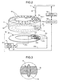
- FIG. 2 is a schematic diagram including an enlarged view of a reaction wheel of the automatic analyzing apparatus shown in FIG. 1 and an overall configuration of the supply apparatus and the agitation apparatus.
- FIG. 3 is an enlarged sectional view of a portion A of the reaction wheel where an extraction electrode is arranged.
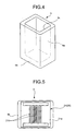
- FIG. 4 is a perspective view of a reaction vessel of the automatic analyzing apparatus according to the first embodiment.
- FIG. 5 is a bottom view of the reaction vessel of FIG. 4 .
- an automatic analyzing apparatus 1 includes a work table 2, and a specimen table 3, a reaction wheel 6, and a reagent table 13 are arranged on the work table 2 separate from each other so as to be freely rotatable and stopped at any position along a circumferential direction.
- the automatic analyzing apparatus 1 further includes an agitation apparatus 20.
- the automatic analyzing apparatus 1 includes a supply apparatus 5 between the specimen table 3 and the reaction wheel 6, and a dispensing device 12 between the reaction wheel 6 and the reagent table 13.
- the specimen table 3 is rotated by a driving unit in a direction indicated by an arrow shown in FIG. 1 .
- the specimen table 3 further includes plural storage chambers 3a arranged equiangularly along an outer circumference thereof. Each storage chamber 3a houses in a detachable manner a specimen vessel 4 which holds a specimen.
- the supply apparatus 5 supplies a specimen such as urine and blood by an amount smaller than an amount of a reagent to a reaction vessel 9.
- the supply apparatus 5 sequentially dispenses the specimen from the plural specimen vessels 4 on the specimen table 3 to the reaction vessel 9 placed in a holder 6a of the reaction wheel 6 using a supply nozzle 5a.
- a supply controller 16c controls timing of supply of the specimen from the supply nozzle 5a to the reaction vessel 9 as shown in FIG. 2 .
- the supply apparatus 5 is also employed for supplying to the reaction vessel 9 a powder-like or a grain-like solid of an amount smaller than the reagent for agitation.
- sample-modified (specimen-modified) or reagent-modified magnetic beads, latex beads, or a liquid in which the beads-like, powder-like or grain-like solid is dispersed may be supplied.
- the reaction wheel 6 is rotated in a direction indicated by an arrow in FIG. 1 by a driving unit which is different from the driving unit of the specimen table 3.
- Plural holders 6a that serve as storage chambers are arranged equiangularly along the outer circumference of the reaction wheel 6.
- the reaction vessel 9 is detachably held in each holder 6a.
- the reaction vessel 9 is an agitation vessel in which the reaction of the specimen and the reagent takes place.
- An opening is formed in each holder 6a at a radially inward side and a radially outward side so that light passes through the opening.
- each holder 6a extraction electrodes 6c are arranged in a radial direction of the reaction wheel 6 penetrating a bottom wall 6b in a vertical direction as shown in FIGS. 2 and 3 .
- the reaction wheel 6 rotates in one cycle by an amount represented as (one round-one reaction vessel)/4 in an anticlockwise direction. Hence, in four cycles, the reaction wheel 6 rotates by an amount corresponding to one reaction vessel 9 in a clockwise direction.
- the reaction wheel 6 may rotate in the clockwise direction.
- the reaction wheel 6 includes a measuring optical system 10 and a discharge device 11.
- the reaction vessel 9 has a very small capacity of approximately a few nL to a few tens ⁇ L.
- the reaction vessel 9 is made of a material which transmits at least 80% of light included in analytical light (of 340 nm to 800 nm) emitted from a light source 10a, and made, for example, of glass such as heat resistance glass, and synthetic resin such as cyclic olefin and polystyrene.
- the reaction vessel 9 has a square-pole-like shape, and has a side wall 9a, a bottom wall 9b, and an opening 9c formed in an upper portion as shown in FIGS. 4 and 5 .
- Liquid affinity treatment is performed on an inner surface of the reaction vessel 9 which holds the liquid such as a specimen and a reagent.
- the reaction vessel 9 a part of each of two side walls 9a facing with each other and parallel with each other is used as a window that transmits the analytical light.
- a surface-acoustic-wave element 21 is attached to a lower surface of the bottom wall 9b of the reaction vessel 9 with an acoustic matching layer therebetween.
- the measuring optical system 10 emits analytical light (of 340 to 800 nm) from the light source 10a for analyzing the liquid in the reaction vessel 9 obtained as a result of reaction between the reagent and the specimen. Beams of analytical light emitted from the light source 10a pass through the liquid in the reaction vessel 9 and are received by a light-receiving element 10b arranged opposite to the light source 10a.
- the discharge device 11 has a discharge nozzle. After the reaction in the reaction vessel 9, the discharge device 11 sucks the liquid with the discharge nozzle and discharges the sucked liquid to a discharge vessel (not shown). The reaction vessel 9 passing through the discharge device 11 is transported to a washing device not shown and washed. The washed reaction vessel is used again for analysis of another specimen.
- the dispensing device 12 dispenses a reagent of a larger amount than a specimen supplied by the supply apparatus 5. As shown in FIG. 1 , the dispensing device 12 sequentially dispenses a reagent from a predetermined reagent vessel 14 on the reagent table 13 to the reaction vessel 9 placed in the holder 6a of the reaction wheel 6.
- a liquid reagent is represented as MR
- an amount of a specimen as MS
- ratio MS/MR of the amount MS of the specimen S to the amount MR of the liquid reagent R is within the range of 1/1000 ⁇ MS/MR ⁇ 1/4.
- MS represents a cubic volume of the solid.
- the reagent table 13 is rotated in a direction indicated by an arrow shown in FIG. 1 by a driving unit different from those for the specimen table 3 and the reaction wheel 6.
- a driving unit different from those for the specimen table 3 and the reaction wheel 6.
- fan-like storage chambers 13a are arranged in a circumferential direction.
- the reagent vessel 14 is placed in a detachable manner in each storage chamber 13a.
- Each of the plural reagent vessels 14 is filled with a predetermined reagent corresponding to each examination item.
- an information recording medium (not shown) recording information concerning the held reagent is pasted.
- a reader device 15 is arranged outside the outer circumference of the reagent table 13.
- the reader device 15 reads out the information concerning the reagent, such as a type, a lot, and a valid date recorded in the information recording medium pasted onto the reagent vessel 14.
- the reader device 15 outputs the read information to the control unit 16.
- the control unit 16 includes an apparatus controller 16a which controls operations of respective units of the automatic analyzing apparatus 1, a supply controller 16c which controls timing of the supply of the specimen from the supply nozzle 5a to the reaction vessel 9, and a linking unit 16b which links the control operations of the supply controller 16c and the drive control circuit 24 with each other.
- a microcomputer provided with a recording function to store results of analysis is used as the control unit 16.
- the control unit 16 is connected to the supply apparatus 5, a light-receiving element 10b, the discharge device 11, the reader device 15, an analyzing unit 17, an input unit 18, a display unit 19, the agitation apparatus 20, and the like.
- the control unit 16 controls an operation of each unit of the automatic analyzing apparatus 1.
- control unit 16 controls the automatic analyzing apparatus 1 so as to restrict the analyzing operation or gives an alarm notification to an operator.
- the linking unit 16b is connected to the apparatus controller 16a and the supply controller 16c to synchronize and link control signals of the apparatus controller 16a and the supply controller 16c.
- the analyzing unit 17 is connected to the light-receiving element 10b via the control unit 16.
- the analyzing unit 17 analyzes constituent concentration and the like of the specimen according to absorbancy of the liquid in the reaction vessel 9 based on the intensity of light received by the light-receiving element 10b, and outputs the result of analysis to the control unit 16.
- the input unit 18 operates to input the examination items and the like into the control unit 16.
- a keyboard or a mouse may be used as the input unit 18.
- the display unit 19 displays contents of analysis, an alarm, and the like, and a display panel or the like may be used as the display unit 19.
- the agitation apparatus 20 agitates the liquid held in the reaction vessel 9 by sound waves.
- the agitation apparatus 20 includes, in addition to the surface-acoustic-wave element 21 attached to the reaction vessel 9, a terminal substrate 22, a signal generator 23, and a drive control circuit 24, as shown in FIG. 2 .
- the surface-acoustic-wave element 21 includes, as shown in FIG. 5 , a piezoelectric substrate 21a of piezoelectric material such as lithium niobate (LiNb03) and a vibrator (sound emitter) 21b of interdigital transducers (IDT) formed thereon.
- a piezoelectric substrate 21a of piezoelectric material such as lithium niobate (LiNb03) and a vibrator (sound emitter) 21b of interdigital transducers (IDT) formed thereon.
- the terminal substrate 22 is a ring-like insulating plate arranged below the reaction wheel 6 as shown in FIG. 2 .
- the terminal substrate 22 does not rotate.
- the supply apparatus 5 supplies the specimen S from the supply nozzle 5a to the reaction vessel 9 held by the holder 6a of a predetermined position among the plural holders 6a. If this position is represented as PN, a range corresponding to a position PN-1 preceding the position PN to a position PN+2 which is two positions subsequent to the position PN is set as an agitation region.
- the terminal substrate 22 includes contact electrodes 22a and 22b arranged in an area corresponding to the agitation region. The contact electrodes 22a and 22b are brought into contact with the extraction electrode 6c to supply power to the vibrator 21b.
- the agitation region is not limited to an area corresponding to four positions PN-1 to PN+2. As far as the agitation region includes the position PN where the supply nozzle 5z supplies the specimen S, the agitation region may be set to a larger range corresponding to more than four positions, or to a smaller range corresponding to less than four positions, as necessary.
- the signal generator 23 connects the contact electrodes 22a and 22b by wires 23a.
- the signal generator 23 outputs high-frequency signals of approximately a few tens MHz to a few hundreds MHz to the surface-acoustic-wave element 21 according to the control signals supplied by the drive control circuit 24, and oscillates the vibrator 21b to generate sound waves.
- the drive control circuit 24 is an electronic control unit (ECU) incorporating a memory and a timer, and controls the drive signals of the surface-acoustic-wave element 21.
- ECU electronice control unit
- the drive control circuit 24 is connected to the supply controller 16c via the linking unit 16b.
- the drive control circuit 24 controls the operation of the signal generator 23, and the control operation of the drive control circuit 24 is linked to the control operation of the supply controller 16c.
- the drive control circuit 24 controls, for example, characteristics (such as frequency, strength, phase, and wave characteristic), waveform (such as sine wave, triangular wave, rectangular wave, and burst wave), modulation (amplitude modulation and frequency modulation), and the like of the sound waves generated by the surface-acoustic-wave element 21 according to an analysis item or the property of the liquid. Further, the drive control circuit 24 can switch the frequency of oscillation signals generated by the signal generator 23 according to the incorporated timer.
- the automatic analyzing apparatus 1 configured as described above agitates the reagent and the specimen by an agitation method described below.
- the reaction vessels 9 placed in the holders 6a move along the circumferential direction following the rotation of the reaction wheel 6.
- a reagent Lr in the predetermined reagent vessel 14 on the reagent table 13 is sequentially dispensed to the reaction vessels 9 through the nozzle of the reagent dispensing mechanism 12 (see FIG. 6 ).
- the extraction electrode 6c arranged in the bottom wall 6b of the reaction wheel 6 touch the contact electrodes 22a and 22b to supply power to the surface-acoustic-wave element 21 as shown in FIG. 7 .
- the vibrator 21b of the surface-acoustic-wave element 21 starts generating the sound waves which are propagated through the piezoelectric substrate 21a, leak through the bottom wall 9b into the reagent Lr, and are emitted to the reagent Lr.
- the sound waves Wa leaking into the reagent Lr generate sound flows in the dispensed reagent Lr. The sound flow starts agitating the reagent Lr.
- the supply nozzle 5a of the supply apparatus 5 dispenses the specimen S to the reagent Lr of the reaction vessel 9 as shown in FIG. 8 . Since the agitation of the reagent Lr in the reaction vessel 9 starts at the previous position PN-1, the reagent is still flowing. Hence, the dispensed specimen S is quickly drawn into the reagent Lr because of the sound flow. More specifically, since the influence of the surface tension of the reagent Lr is suppressed, the dispensed specimen S is not adsorbed to the surface of the reagent Lr by the surface tension.
- the agitation method of the present invention is characterized in that a second liquid, i.e., the specimen S is supplied while a first liquid, i.e., the reagent Lr is agitated.
- the reaction vessel 9 moves to the position PN+1 according to the rotation of the reaction wheel 6, the sound flow generated by the sound wave Wa leaking out into the reagent Lr agitates the specimen S and makes the specimen S spread in the reagent Lr as shown in FIG. 9 .
- the reaction vessel 9 reaches the position PN+2
- the specimen S further spreads extensively in the reagent Lr because of the agitation by the sound flow, whereby the specimen S and the reagent Lr are efficiently agitated and their reaction is enhanced.
- the automatic analyzing apparatus 1 can agitate the reagent Lr and the specimen S uniformly in a short time.
- the extraction electrode 6c arranged in the bottom wall 6b of the reaction wheel 6 are brought out of contact from the contact electrodes 22a and 22b, whereby the power supply to the surface-acoustic-wave element 21 stops.
- the vibrator 21b of the surface-acoustic-wave element 21 stops generating the sound waves and the agitation of the reagent Lr and the specimen S in the reaction vessel 9 stops.
- reaction liquid of the reagent Lr and the specimen S is subjected to photometry with the use of light flux emitted from the light source 10a of the measuring optical system 10.
- the reaction wheel 6 further rotates to make a waste of the reaction liquid remaining in the reaction vessel 9 discharged by the discharge device 11.
- the washing device not shown washes the reaction vessel 9, the reaction vessel 9 is used again for the analysis of the specimen.
- the drive control circuit 24 controls the generation of sound waves by the surface-acoustic-wave element 21 so that the reagent Lr is agitated when the specimen S is supplied.
- the automatic analyzing apparatus 1, the supply apparatus 5, the agitation apparatus 20, and the agitation method according to the first embodiment can agitate the reagent Lr and the specimen S uniformly even when a small amount of specimen S is supplied to a large amount of reagent Lr.
- the automatic analyzing apparatus includes the surface-acoustic-wave element 21 which serves as a sound wave generator and is attached to the reaction vessel 9, and the surface-acoustic-wave element 21 is connected to the signal generator 23 via the extraction electrode 6c formed in the reaction wheel 6 and the terminal substrate 22.
- the sound wave generator is arranged in a sound wave generating substrate which corresponds to the terminal substrate 22.
- FIG. 11 shows an enlarged view of the reaction wheel of the automatic analyzing apparatus according to the second embodiment, together with an overall configuration of a supply apparatus and an agitation apparatus.
- FIG. 12 is an enlarged plan view of a portion of the sound wave generating substrate where the sound wave generator is arranged.
- the automatic analyzing apparatus, the supply apparatus, and the agitation apparatus according to the second embodiment have the same configurations as the automatic analyzing apparatus, the supply apparatus, and the agitation apparatus shown in FIG. 1 except the configuration of the sound wave generating substrate. Elements having the same configuration as those of the first embodiment will be denoted by the same reference characters in the description.
- the reaction wheel has the holder 6a which does not have a bottom portion, and has an opening instead.
- the sound wave generator is arranged in a sound wave generating substrate 26 and not in the reaction vessel 9.
- the sound wave generating substrate 26 does not rotate similarly to the terminal substrate 22.
- the sound wave generating substrate 26 includes a ring-like piezoelectric substrate 26a and vibrators (sound emitter) 26b of interdigital transducers (IDT) arranged on the upper surface of the piezoelectric substrate 26a at four positions along the circumferential direction at intervals corresponding to the intervals of the arranged positions of the plural holders 6a.
- IDT interdigital transducers
- the acoustic matching layer 27 is a liquid such as water, or gel, for example.
- the reaction wheel 6 is arranged on the sound wave generating substrate 26 via the acoustic matching layer 27. Even though the automatic analyzing apparatus 1 uses the sound wave generating substrate 26 in place of the terminal substrate 22, when the reaction vessels 9 are placed in the holders 6a, respectively, and the reaction vessels 9 sequentially move through the agitation region from the position PN-1 to the position PN+2 according to the rotation of the reaction wheel 6, the sound wave generated by the vibrator 26b is emitted through the bottom wall 9b of the reaction vessel 9 to the reagent Lr.
- the drive control circuit 24 controls the vibrator 26b so that the supply apparatus 5 supplies the specimen S while the reagent Lr is agitated.
- the automatic analyzing apparatus 1, the supply apparatus 5, the agitation apparatus 20, and the agitation method according to the second embodiment can agitate the reagent Lr and the specimen S uniformly even when a small amount of specimen S is supplied to a large amount of reagent Lr.
- the agitation region is set to the contiguous range from the position PN-1 to the position PN+2 around the position PN where the supply apparatus 5 supplies the specimen S through the supply nozzle 5a.
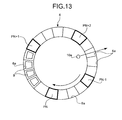
- the positions PN-1, PN+1, and PN+2 can be arranged separately from the position PN as in the reaction wheel 6 shown in FIG. 13 .
- the automatic analyzing apparatus 1 and the agitation apparatus 20 according to the first embodiment use the terminal substrate 22 and supply the power to the vibrator 21b by bringing the extraction electrode 6c and the contact electrodes 22a and 22b in contact with each other in the agitation region according to the rotation of the reaction wheel 6, whereby the liquid held in the reaction vessel 9 is agitated.
- the automatic analyzing apparatus 1 and the agitation apparatus 20 according to the second embodiment use the sound wave generating substrate 26 and agitate the liquid held in the reaction vessel 9 when the position of the reaction vessel 9 coincides with the position of the vibrator 26b in the agitation region according to the rotation of the reaction wheel 6.
- the liquid held in the reaction vessel 9 is agitated only intermittently when the reaction vessel 9 stops at the positions PN-1 to PN+2 in the agitation region according to the rotation of the reaction wheel 6.
- the automatic analyzing apparatus 1 of the first embodiment can use an agitation apparatus 30 shown in FIG. 14 in place of the agitation apparatus 20.
- the agitation apparatus 30 includes a signal transmitting unit 31, a drive controller 32, and plural agitation driving units 33.
- the signal transmitting unit 31 includes a slip ring which transmits direct-current power-supply signals supplied from a power supply unit 1a of the automatic analyzing apparatus 1 and alternate-current control signals supplied from the apparatus controller 16a.
- the drive controller 32 corresponds to the drive control circuit 24, and controls the agitation driving unit 33 to control the agitation operation of the surface-acoustic-wave element 21 based on the control signals supplied from the signal transmitting unit 31.
- the agitation driving unit 33 corresponds to the signal generator 23 and outputs driving signals for agitating the liquid in the reaction vessel 9 according to the control signals supplied from the drive controller 32.
- each of the agitation driving units 33 plural combinations of the surface-acoustic-wave element 21 and a switch 34 are connected in parallel.
- the switch 34 serves to switch over electrical connection states (on and off) of the surface-acoustic-wave element 21.
- the switch 34 is a high-frequency relay, a high-frequency semiconductor switch, and the like.
- the drive controller 32 controls the operation of the switch 34.
- the parallel-connected plural switches 34 one is always turned on so that the impedance matching of each combination of the agitation driving unit 33 and the surface-acoustic-wave element 21 is maintained.
- the same number of combinations of switch 34 and the surface-acoustic-wave element 21 may be connected to every agitation driving unit 33, or the number of combinations connected may be different for each agitation driving unit 33.
- the automatic analyzing apparatus 1 of the first embodiment can continuously agitate the liquid held in the reaction vessel 9 while the reaction wheel 6 is rotating as well as when the reaction wheel 6 is in halt by constantly sending the power-supply signals and the control signals to the agitation apparatus 30 regardless of the rotating position of the reaction wheel 6.
- the driving controller 32 and the agitation driving unit 33 do not need to be arranged on the reaction wheel 6.
- the driving controller 32 and the agitation driving unit 33 may be arranged outside the reaction wheel 6, in other words, they may be connected to the switch 34 via the signal transmitting unit 31. When the driving controller 32 and the agitation driving unit 33 are arranged outside the reaction wheel 6, weight load of the reaction wheel 6 can be reduced.
- the surface-acoustic-wave element 21 which serves as the sound wave generator may be arranged on the side wall 9a of the reaction vessel 9 as shown in FIG. 15 .
- the extraction electrode 6c is arranged so as to penetrate the side wall 6d of the reaction wheel 6 in the radial direction.
- the terminal substrate 22 includes contact electrodes 22a and 22b that are arranged outside the outer circumference of the reaction wheel 6 within the agitation region corresponding to the range of the position PN-1 to the position PN+2 to be brought into contact with the extraction electrode 6c and to supply power to the vibrator 21b.
- the agitation region is not limited to an area corresponding to four positions PN-1 to PN+2.
- the agitation region includes the position PN where the supply nozzle 5a supplies the specimen S
- the agitation region may be set to a larger range corresponding to more than four positions, or to a smaller range corresponding to less than four positions, as necessary.
- the surface-acoustic-wave element 21 is arranged on the side wall 9a of the reaction vessel 9 and the terminal substrate 22 is arranged outside the outer circumference of the reaction wheel 6, a degree of freedom in designing the automatic analyzing apparatus 1 increases.
- the drive controller controls the sound wave generator so that the sound flow is generated in the first liquid by the sound waves when the second liquid or the solid supplied by the supply unit is brought into contact with the first liquid.
- the analyzing apparatus of the present invention may supply the second liquid or the solid to the vessel while the sound flow is generated in the first liquid.
- the sound wave generator of the analyzing apparatus or the agitation apparatus may well be activated or stopped. Therefore, the analyzing apparatus and the agitation apparatus may supply the second liquid or the solid to the vessel at such timing that the sound flow still remains in the first liquid because of the sound waves previously generated by the sound wave generator even though the sound wave generator is currently stopped.
- the analyzing apparatus, the supply apparatus, the agitation apparatus, and the agitation method according to the present invention are useful for agitating the first liquid and the second liquid or the solid uniformly by supplying a small amount of the second liquid or the solid to a large amount of the first liquid being agitated, and more particularly, are suitable for uniformly agitating the reagent and the specimen in the automatic analyzing apparatus.
Landscapes
- Chemical & Material Sciences (AREA)
- Chemical Kinetics & Catalysis (AREA)
- Physics & Mathematics (AREA)
- Health & Medical Sciences (AREA)
- Life Sciences & Earth Sciences (AREA)
- Analytical Chemistry (AREA)
- Biochemistry (AREA)
- General Health & Medical Sciences (AREA)
- General Physics & Mathematics (AREA)
- Immunology (AREA)
- Pathology (AREA)
- Automatic Analysis And Handling Materials Therefor (AREA)
Abstract
An analyzing apparatus (1), a supply apparatus, an agitation apparatus, and an agitation method for agitating plural different types of liquids to cause reaction and to analyze a reaction liquid. The analyzing apparatus (1) includes a surface-acoustic-wave element that generates a sound wave to agitate a liquid held in a vessel, a supply apparatus (5) that supplies, to a vessel holding a first liquid and transported, a second liquid or a solid of an amount smaller than an amount of the first liquid, and a drive controller that controls generation of the sound wave by the surface-acoustic-wave element so that the first liquid is agitated when the supply apparatus (5) supplies the second liquid or the solid.
Description
- The present invention relates to an analyzing apparatus, a supply apparatus, an agitation apparatus, and an agitation method.
- Some conventionally known analyzing apparatuses radiate ultrasound to a reaction vessel from outside of the reaction vessel to generate a sound flow in a liquid held in the reaction vessel to thereby agitate and mix the liquid in a non-contact manner in order to downsize the reaction vessel and to prevent contamination of specimens (see, for example, Patent Document 1).
- Patent Document 1: PCT International Publication No.
01/77691 - A chemical analyzing apparatus disclosed in
Patent Document 1 dispenses a large amount of reagent into a reaction vessel which holds a small amount of specimen while performing agitation at the same time. Hence, the chemical analyzing apparatus ofPatent Document 1 can uniformly agitate the specimen and the reagent because of an effect of agitation obtained from generation of sound flows caused by radiation of ultrasounds, and an effect of agitation obtained from the dispensing itself of the large amount of reagent to the small amount of specimen. However, when the capacity of the reaction vessel is very small, an influence of surface tension of the held liquid increases. Therefore, if a procedure inverse to the one taken for the chemical analyzing apparatus ofPatent Document 1 is taken and a small amount of specimen is dispensed into a very small reaction vessel holding a large amount of reagent, the specimen is adsorbed to a liquid surface because of the surface tension of the reagent. Then, the specimen spreads only in the vicinity of the liquid surface and hardly spreads into the reagent of a large amount. In this case, plural different types of liquids cannot be mixed uniformly unless agitation efficiency is enhanced through increased agitation energy, for example, by an increased agitation time or an increased agitation power in a subsequent agitation process, and otherwise the reliability of analysis value is compromised. When the capacity of the reaction vessel is very small and a small amount of powder-like or grain-like solid substance is put into a large amount of liquid and agitated, the same problem arises. - In view of the above, an object of the present invention is to provide an analyzing apparatus, a supply apparatus, an agitation apparatus, and an agitation method which can realize uniform agitation even when a small amount of liquid or solid is put into a large amount of liquid.
- To solve the problem as described above and to achieve an object, an analyzing apparatus according to
claim 1 is an analyzing apparatus for agitating plural different types of liquids to cause reaction to analyze a reaction liquid, and includes a sound wave generator that generates a sound wave to agitate a liquid held in a vessel, a supply unit that supplies, to the vessel holding a first liquid and transported, a second liquid or a solid of an amount smaller than an amount of the first liquid, and a drive controller that controls generation of the sound wave by the sound wave generator so that the first liquid is agitated when the supply unit supplies the second liquid or the solid. - Further, in the analyzing apparatus according to the present invention as recited in
claim 2, the sound wave generator is held at a fixed relative position with respect to the vessel. - Further, in the analyzing apparatus according to the present invention as recited in
claim 3, the sound wave generator is arranged on a bottom wall of the vessel. - Further, in the analyzing apparatus according to the present invention as recited in claim 4, the sound wave generator is arranged on a side wall of the vessel.
- Further, in the analyzing apparatus according to the present invention as recited in
claim 5, the drive controller controls the sound wave generator so that the sound wave is generated after the first liquid is dispensed into the vessel and before the supply unit supplies the second liquid or the solid into the vessel. - Further, in the analyzing apparatus according to the present invention as recited in
claim 6, the supply unit moves between the vessel holding the first liquid and a supply source of the second liquid or the solid, and the drive controller controls the sound wave generator so that the sound wave is generated when the supply unit moves to a position for supplying the second liquid or the solid. - Further, in the analyzing apparatus according to the present invention as recited in claim 7, the drive controller controls the sound wave generator so that the sound wave is generated before the vessel holding the first liquid is transported to a position where the second liquid or the solid is supplied.
- Further, in the analyzing apparatus according to the present invention as recited in claim 8, the sound wave generator is a surface-acoustic-wave element that generates a surface acoustic wave.
- Further, to solve the problems as described above and to achieve an object, a supply apparatus according to
claim 9 is a supply apparatus for supplying a liquid or a solid to a vessel, and includes a supply unit that supplies, to a vessel holding a first liquid, a second liquid or a solid, and a supply controller that controls timing of supply of the second liquid or the solid to the vessel by the supply unit, wherein the supply controller controls the supply unit so that the supply unit supplies the second liquid or the solid of an amount smaller than an amount of the first liquid after the first liquid is dispensed into the vessel. - Further, to solve the problems as described above and to achieve an object, an agitation apparatus according to
claim 10 is an agitation apparatus for agitating a first liquid held in a vessel by irradiating a sound wave, and includes a sound wave generator that generates the sound wave, and a drive controller that controls timing of generation of the sound wave by the sound wave generator, wherein the drive controller controls the generation of the sound wave by the sound wave generator so that the first liquid is agitated when a second liquid or a solid is supplied to the vessel. - Further, to solve the problems as described above and to achieve an object, a method of agitation according to
claim 11 is an agitation method for agitating a first liquid and a second liquid or a solid of an amount smaller than an amount of the first liquid, wherein the second liquid or the solid is supplied while the first liquid is agitated. - An expression that "the first liquid is agitated" in the description means that the first liquid is agitated by a sound flow produced by sound waves generated by the sound wave generator. However, the sound wave generator is not always in an operating state when the first liquid is agitated. For example, even after the sound wave generator stops operation, the sound waves generated before the sound wave generator stops operation remain and generate sound flows in the first liquid. Such state is also described as a state where "the first liquid is agitated".
- In the analyzing apparatus, the agitation apparatus, and the agitation method according to the present invention, the drive controller controls the generation of sound wave by the sound wave generator so that the first liquid is agitated when the second liquid or the solid is supplied. Further, in the supply apparatus according to the present invention, the supply controller controls the supply unit so that the second liquid or the solid of a smaller amount than the first liquid is supplied after the first liquid is dispensed to the vessel. Therefore, according to the present invention, even when a small amount of the second liquid or the solid is supplied to a large amount of the first liquid, the first liquid is agitated when the second liquid or the solid is supplied, whereby the analyzing apparatus, the supply apparatus, the agitation apparatus, and the agitation method that can uniformly agitate the first liquid and the second liquid or the solid can be provided.
-
-
FIG. 1 is a schematic configuration diagram of an automatic analyzing apparatus and a supply apparatus according to a first embodiment; -
FIG. 2 is a schematic diagram including an enlarged view of a reaction wheel of the automatic analyzing apparatus shown inFIG. 1 and an overall configuration diagram of the supply apparatus and an agitation apparatus; -
FIG. 3 is an enlarged sectional view of a portion A of the reaction wheel where an extraction electrode is arranged; -
FIG. 4 is a perspective view of a reaction vessel of the automatic analyzing apparatus according to the first embodiment; -
FIG. 5 is a bottom view of the reaction vessel ofFIG. 4 ; -
FIG. 6 is a sectional view of the reaction vessel which is placed in a holder of the reaction wheel and to which a reagent is being dispensed; -
FIG. 7 is a sectional view of the reaction vessel located at a position PN-1 in an agitation region wherein sound waves generated by a surface-acoustic-wave element are emitted to a reagent in the reaction vessel so that agitation of the reagent starts; -
FIG. 8 is a sectional view of the reaction vessel located at a position PN in the agitation region wherein a specimen is dispensed to the agitated reagent; -
FIG. 9 is a sectional view of the reaction vessel located at a position PN+1 in the agitation region wherein the specimen agitated by a sound flow spreads in the reagent; -
FIG. 10 is a sectional view of the reaction vessel located at a position PN+2 in the agitation region wherein the specimen agitated by the sound flow spreads further extensively in the reagent; -
FIG. 11 is a diagram including an enlarged view of a reaction wheel of an automatic analyzing apparatus of a second embodiment and an overall configuration diagram of a supply apparatus and an agitation apparatus; -
FIG. 12 is an enlarged plan view of a portion of a sound wave generating substrate where sound wave generators are arranged; -
FIG. 13 is a plan view of the reaction wheel showing a modification of an arrangement of the agitation region; -
FIG. 14 is a physical configuration diagram of a modification of the agitation apparatus; and -
FIG. 15 is a sectional view of a main part of a modification of the automatic analyzing apparatus in which the sound wave generator is arranged on a side wall of the reaction vessel. -
- 1
- Automatic analyzing apparatus
- 1a
- Power supply unit
- 2
- Work table
- 3
- Specimen table
- 4
- Specimen vessel
- 5
- Supply apparatus
- 5a
- Supply nozzle
- 6
- Reaction wheel
- 6a
- Holder
- 6c
- Extraction electrode
- 9
- Reaction vessel
- 10
- Measuring optical system
- 10a
- Light source
- 10b
- Light-receiving element
- 11
- Discharge device
- 12
- Dispensing device
- 13
- Reagent table
- 14
- Reagent vessel
- 15
- Reader device
- 16
- Control unit
- 16a
- Apparatus controller
- 16b
- Linking unit
- 16c
- Supply controller
- 17
- Analyzing unit
- 18
- Input unit
- 19
- Display unit
- 20
- Agitation apparatus
- 21
- Surface-acoustic-wave element
- 22
- Terminal substrate
- 23
- Signal generator
- 24
- Drive control circuit
- 26
- Sound wave generating substrate
- 26a
- Piezoelectric substrate
- 26b
- Vibrator
- 27
- Acoustic matching layer
- 30
- Agitation apparatus
- 31
- Signal transmitting unit
- 32
- Drive controller
- 33
- Agitation driving unit
- 34
- Switch
- PN-1 to PN+2
- Position
- Wa
- Sound wave
- An analyzing apparatus, a supply apparatus, an agitation apparatus, and an agitation method according to a first embodiment of the present invention will be described in detail below with reference to the accompanying drawings.
FIG. 1 is a schematic configuration diagram of an automatic analyzing apparatus and the supply apparatus according to the first embodiment.FIG. 2 is a schematic diagram including an enlarged view of a reaction wheel of the automatic analyzing apparatus shown inFIG. 1 and an overall configuration of the supply apparatus and the agitation apparatus.FIG. 3 is an enlarged sectional view of a portion A of the reaction wheel where an extraction electrode is arranged.FIG. 4 is a perspective view of a reaction vessel of the automatic analyzing apparatus according to the first embodiment.FIG. 5 is a bottom view of the reaction vessel ofFIG. 4 . - As shown in
FIGS. 1 and2 , anautomatic analyzing apparatus 1 includes a work table 2, and a specimen table 3, areaction wheel 6, and a reagent table 13 are arranged on the work table 2 separate from each other so as to be freely rotatable and stopped at any position along a circumferential direction. Theautomatic analyzing apparatus 1 further includes anagitation apparatus 20. Further, theautomatic analyzing apparatus 1 includes asupply apparatus 5 between the specimen table 3 and thereaction wheel 6, and adispensing device 12 between thereaction wheel 6 and the reagent table 13. - The specimen table 3 is rotated by a driving unit in a direction indicated by an arrow shown in
FIG. 1 . The specimen table 3 further includesplural storage chambers 3a arranged equiangularly along an outer circumference thereof. Eachstorage chamber 3a houses in a detachable manner a specimen vessel 4 which holds a specimen. - The
supply apparatus 5 supplies a specimen such as urine and blood by an amount smaller than an amount of a reagent to areaction vessel 9. As shown inFIGS. 1 and2 , thesupply apparatus 5 sequentially dispenses the specimen from the plural specimen vessels 4 on the specimen table 3 to thereaction vessel 9 placed in aholder 6a of thereaction wheel 6 using asupply nozzle 5a. In thesupply apparatus 5, asupply controller 16c controls timing of supply of the specimen from thesupply nozzle 5a to thereaction vessel 9 as shown inFIG. 2 . Thesupply apparatus 5 is also employed for supplying to thereaction vessel 9 a powder-like or a grain-like solid of an amount smaller than the reagent for agitation. For example, sample-modified (specimen-modified) or reagent-modified magnetic beads, latex beads, or a liquid in which the beads-like, powder-like or grain-like solid is dispersed may be supplied. - The
reaction wheel 6 is rotated in a direction indicated by an arrow inFIG. 1 by a driving unit which is different from the driving unit of the specimen table 3.Plural holders 6a that serve as storage chambers are arranged equiangularly along the outer circumference of thereaction wheel 6. Thereaction vessel 9 is detachably held in eachholder 6a. Thereaction vessel 9 is an agitation vessel in which the reaction of the specimen and the reagent takes place. An opening is formed in eachholder 6a at a radially inward side and a radially outward side so that light passes through the opening. Further, in eachholder 6a,extraction electrodes 6c are arranged in a radial direction of thereaction wheel 6 penetrating abottom wall 6b in a vertical direction as shown inFIGS. 2 and 3 . Thereaction wheel 6 rotates in one cycle by an amount represented as (one round-one reaction vessel)/4 in an anticlockwise direction. Hence, in four cycles, thereaction wheel 6 rotates by an amount corresponding to onereaction vessel 9 in a clockwise direction. Thereaction wheel 6 may rotate in the clockwise direction. Thereaction wheel 6 includes a measuringoptical system 10 and adischarge device 11. - The
reaction vessel 9 has a very small capacity of approximately a few nL to a few tens µL. Thereaction vessel 9 is made of a material which transmits at least 80% of light included in analytical light (of 340 nm to 800 nm) emitted from alight source 10a, and made, for example, of glass such as heat resistance glass, and synthetic resin such as cyclic olefin and polystyrene. Thereaction vessel 9 has a square-pole-like shape, and has aside wall 9a, abottom wall 9b, and anopening 9c formed in an upper portion as shown inFIGS. 4 and 5 . Liquid affinity treatment is performed on an inner surface of thereaction vessel 9 which holds the liquid such as a specimen and a reagent. In thereaction vessel 9, a part of each of twoside walls 9a facing with each other and parallel with each other is used as a window that transmits the analytical light. As shown inFIG. 5 , a surface-acoustic-wave element 21 is attached to a lower surface of thebottom wall 9b of thereaction vessel 9 with an acoustic matching layer therebetween. - The measuring
optical system 10 emits analytical light (of 340 to 800 nm) from thelight source 10a for analyzing the liquid in thereaction vessel 9 obtained as a result of reaction between the reagent and the specimen. Beams of analytical light emitted from thelight source 10a pass through the liquid in thereaction vessel 9 and are received by a light-receivingelement 10b arranged opposite to thelight source 10a. On the other hand, thedischarge device 11 has a discharge nozzle. After the reaction in thereaction vessel 9, thedischarge device 11 sucks the liquid with the discharge nozzle and discharges the sucked liquid to a discharge vessel (not shown). Thereaction vessel 9 passing through thedischarge device 11 is transported to a washing device not shown and washed. The washed reaction vessel is used again for analysis of another specimen. - The dispensing
device 12 dispenses a reagent of a larger amount than a specimen supplied by thesupply apparatus 5. As shown inFIG. 1 , the dispensingdevice 12 sequentially dispenses a reagent from apredetermined reagent vessel 14 on the reagent table 13 to thereaction vessel 9 placed in theholder 6a of thereaction wheel 6. When an amount of a liquid reagent is represented as MR, and an amount of a specimen as MS, ratio MS/MR of the amount MS of the specimen S to the amount MR of the liquid reagent R is within the range of 1/1000≤MS/MR≤1/4. When the specimen supplied to thereaction vessel 9 by thesupply apparatus 5 to be agitated with the reagent is a powder-like or a grain-like solid, MS represents a cubic volume of the solid. - The reagent table 13 is rotated in a direction indicated by an arrow shown in
FIG. 1 by a driving unit different from those for the specimen table 3 and thereaction wheel 6. On the reagent table 13, fan-like storage chambers 13a are arranged in a circumferential direction. Thereagent vessel 14 is placed in a detachable manner in eachstorage chamber 13a. Each of theplural reagent vessels 14 is filled with a predetermined reagent corresponding to each examination item. On an outer surface of thereagent vessel 14, an information recording medium (not shown) recording information concerning the held reagent is pasted. - A
reader device 15 is arranged outside the outer circumference of the reagent table 13. Thereader device 15 reads out the information concerning the reagent, such as a type, a lot, and a valid date recorded in the information recording medium pasted onto thereagent vessel 14. Thereader device 15 outputs the read information to thecontrol unit 16. - The
control unit 16 includes anapparatus controller 16a which controls operations of respective units of theautomatic analyzing apparatus 1, asupply controller 16c which controls timing of the supply of the specimen from thesupply nozzle 5a to thereaction vessel 9, and a linkingunit 16b which links the control operations of thesupply controller 16c and thedrive control circuit 24 with each other. For example, a microcomputer provided with a recording function to store results of analysis is used as thecontrol unit 16. Thecontrol unit 16 is connected to thesupply apparatus 5, a light-receivingelement 10b, thedischarge device 11, thereader device 15, an analyzingunit 17, aninput unit 18, adisplay unit 19, theagitation apparatus 20, and the like. Thecontrol unit 16 controls an operation of each unit of theautomatic analyzing apparatus 1. Further, when the lot or the valid date of the reagent according to the information read out from the information recording medium is not within a set range, thecontrol unit 16 controls theautomatic analyzing apparatus 1 so as to restrict the analyzing operation or gives an alarm notification to an operator. In thecontrol unit 16, the linkingunit 16b is connected to theapparatus controller 16a and thesupply controller 16c to synchronize and link control signals of theapparatus controller 16a and thesupply controller 16c. - The analyzing
unit 17 is connected to the light-receivingelement 10b via thecontrol unit 16. The analyzingunit 17 analyzes constituent concentration and the like of the specimen according to absorbancy of the liquid in thereaction vessel 9 based on the intensity of light received by the light-receivingelement 10b, and outputs the result of analysis to thecontrol unit 16. Theinput unit 18 operates to input the examination items and the like into thecontrol unit 16. For example, a keyboard or a mouse may be used as theinput unit 18. Thedisplay unit 19 displays contents of analysis, an alarm, and the like, and a display panel or the like may be used as thedisplay unit 19. - The
agitation apparatus 20 agitates the liquid held in thereaction vessel 9 by sound waves. Theagitation apparatus 20 includes, in addition to the surface-acoustic-wave element 21 attached to thereaction vessel 9, aterminal substrate 22, asignal generator 23, and adrive control circuit 24, as shown inFIG. 2 . - The surface-acoustic-
wave element 21 includes, as shown inFIG. 5 , apiezoelectric substrate 21a of piezoelectric material such as lithium niobate (LiNb03) and a vibrator (sound emitter) 21b of interdigital transducers (IDT) formed thereon. - The
terminal substrate 22 is a ring-like insulating plate arranged below thereaction wheel 6 as shown inFIG. 2 . Theterminal substrate 22 does not rotate. Thesupply apparatus 5 supplies the specimen S from thesupply nozzle 5a to thereaction vessel 9 held by theholder 6a of a predetermined position among theplural holders 6a. If this position is represented as PN, a range corresponding to a position PN-1 preceding the position PN to a position PN+2 which is two positions subsequent to the position PN is set as an agitation region. Theterminal substrate 22 includescontact electrodes contact electrodes extraction electrode 6c to supply power to thevibrator 21b. The agitation region is not limited to an area corresponding to four positions PN-1 to PN+2. As far as the agitation region includes the position PN where the supply nozzle 5z supplies the specimen S, the agitation region may be set to a larger range corresponding to more than four positions, or to a smaller range corresponding to less than four positions, as necessary. - As shown in
FIG. 2 , thesignal generator 23 connects thecontact electrodes wires 23a. Thesignal generator 23 outputs high-frequency signals of approximately a few tens MHz to a few hundreds MHz to the surface-acoustic-wave element 21 according to the control signals supplied by thedrive control circuit 24, and oscillates thevibrator 21b to generate sound waves. Thedrive control circuit 24 is an electronic control unit (ECU) incorporating a memory and a timer, and controls the drive signals of the surface-acoustic-wave element 21. - The
drive control circuit 24 is connected to thesupply controller 16c via the linkingunit 16b. Thedrive control circuit 24 controls the operation of thesignal generator 23, and the control operation of thedrive control circuit 24 is linked to the control operation of thesupply controller 16c. Thedrive control circuit 24 controls, for example, characteristics (such as frequency, strength, phase, and wave characteristic), waveform (such as sine wave, triangular wave, rectangular wave, and burst wave), modulation (amplitude modulation and frequency modulation), and the like of the sound waves generated by the surface-acoustic-wave element 21 according to an analysis item or the property of the liquid. Further, thedrive control circuit 24 can switch the frequency of oscillation signals generated by thesignal generator 23 according to the incorporated timer. - The
automatic analyzing apparatus 1 configured as described above agitates the reagent and the specimen by an agitation method described below. Thereaction vessels 9 placed in theholders 6a move along the circumferential direction following the rotation of thereaction wheel 6. A reagent Lr in thepredetermined reagent vessel 14 on the reagent table 13 is sequentially dispensed to thereaction vessels 9 through the nozzle of the reagent dispensing mechanism 12 (seeFIG. 6 ). When thereaction vessel 9 in which the reagent is dispensed moves to the agitation region according to the rotation of thereaction wheel 6 and reaches the position PN-1, theextraction electrode 6c arranged in thebottom wall 6b of thereaction wheel 6 touch thecontact electrodes wave element 21 as shown inFIG. 7 . Thus, thevibrator 21b of the surface-acoustic-wave element 21 starts generating the sound waves which are propagated through thepiezoelectric substrate 21a, leak through thebottom wall 9b into the reagent Lr, and are emitted to the reagent Lr. As a result, in thereaction vessel 9, the sound waves Wa leaking into the reagent Lr generate sound flows in the dispensed reagent Lr. The sound flow starts agitating the reagent Lr. - When the
reaction vessel 9 moves according to the rotation of thereaction wheel 6 to the position PN where the specimen S is supplied to thereaction vessel 9, thesupply nozzle 5a of thesupply apparatus 5 dispenses the specimen S to the reagent Lr of thereaction vessel 9 as shown inFIG. 8 . Since the agitation of the reagent Lr in thereaction vessel 9 starts at the previous position PN-1, the reagent is still flowing. Hence, the dispensed specimen S is quickly drawn into the reagent Lr because of the sound flow. More specifically, since the influence of the surface tension of the reagent Lr is suppressed, the dispensed specimen S is not adsorbed to the surface of the reagent Lr by the surface tension. Thus, the agitation method of the present invention is characterized in that a second liquid, i.e., the specimen S is supplied while a first liquid, i.e., the reagent Lr is agitated. - As the
reaction vessel 9 moves to the position PN+1 according to the rotation of thereaction wheel 6, the sound flow generated by the sound wave Wa leaking out into the reagent Lr agitates the specimen S and makes the specimen S spread in the reagent Lr as shown inFIG. 9 . As shown inFIG. 10 , when thereaction vessel 9 reaches the position PN+2, the specimen S further spreads extensively in the reagent Lr because of the agitation by the sound flow, whereby the specimen S and the reagent Lr are efficiently agitated and their reaction is enhanced. In comparison with an apparatus which starts agitation after the specimen S is dispensed to the reagent Lr, theautomatic analyzing apparatus 1 can agitate the reagent Lr and the specimen S uniformly in a short time. - When the
reaction vessel 9 moves out of the agitation region according to the rotation of thereaction wheel 6, theextraction electrode 6c arranged in thebottom wall 6b of thereaction wheel 6 are brought out of contact from thecontact electrodes wave element 21 stops. Thus, thevibrator 21b of the surface-acoustic-wave element 21 stops generating the sound waves and the agitation of the reagent Lr and the specimen S in thereaction vessel 9 stops. - After sufficient agitation, the reaction liquid of the reagent Lr and the specimen S is subjected to photometry with the use of light flux emitted from the
light source 10a of the measuringoptical system 10. After the photometry, thereaction wheel 6 further rotates to make a waste of the reaction liquid remaining in thereaction vessel 9 discharged by thedischarge device 11. After the washing device (not shown) washes thereaction vessel 9, thereaction vessel 9 is used again for the analysis of the specimen. - As can be seen from the foregoing, in the
automatic analyzing apparatus 1 of the first embodiment, thedrive control circuit 24 controls the generation of sound waves by the surface-acoustic-wave element 21 so that the reagent Lr is agitated when the specimen S is supplied. Thus, theautomatic analyzing apparatus 1, thesupply apparatus 5, theagitation apparatus 20, and the agitation method according to the first embodiment can agitate the reagent Lr and the specimen S uniformly even when a small amount of specimen S is supplied to a large amount of reagent Lr. - An analyzing apparatus, a supply apparatus, an agitation apparatus, and an agitation method according to a second embodiment of the present invention will be described in detail below with reference to the accompanying drawings. The automatic analyzing apparatus according to the first embodiment includes the surface-acoustic-
wave element 21 which serves as a sound wave generator and is attached to thereaction vessel 9, and the surface-acoustic-wave element 21 is connected to thesignal generator 23 via theextraction electrode 6c formed in thereaction wheel 6 and theterminal substrate 22. On the other hand, in the automatic analyzing apparatus according to the second embodiment, the sound wave generator is arranged in a sound wave generating substrate which corresponds to theterminal substrate 22.FIG. 11 shows an enlarged view of the reaction wheel of the automatic analyzing apparatus according to the second embodiment, together with an overall configuration of a supply apparatus and an agitation apparatus.FIG. 12 is an enlarged plan view of a portion of the sound wave generating substrate where the sound wave generator is arranged. The automatic analyzing apparatus, the supply apparatus, and the agitation apparatus according to the second embodiment have the same configurations as the automatic analyzing apparatus, the supply apparatus, and the agitation apparatus shown inFIG. 1 except the configuration of the sound wave generating substrate. Elements having the same configuration as those of the first embodiment will be denoted by the same reference characters in the description. - The reaction wheel has the
holder 6a which does not have a bottom portion, and has an opening instead. Further, the sound wave generator is arranged in a soundwave generating substrate 26 and not in thereaction vessel 9. The soundwave generating substrate 26 does not rotate similarly to theterminal substrate 22. As shown inFIGS. 11 and12 , the soundwave generating substrate 26 includes a ring-likepiezoelectric substrate 26a and vibrators (sound emitter) 26b of interdigital transducers (IDT) arranged on the upper surface of thepiezoelectric substrate 26a at four positions along the circumferential direction at intervals corresponding to the intervals of the arranged positions of theplural holders 6a. On the upper surface of the soundwave generating substrate 26, anacoustic matching layer 27 is arranged. Theacoustic matching layer 27 is a liquid such as water, or gel, for example. - The
reaction wheel 6 is arranged on the soundwave generating substrate 26 via theacoustic matching layer 27. Even though theautomatic analyzing apparatus 1 uses the soundwave generating substrate 26 in place of theterminal substrate 22, when thereaction vessels 9 are placed in theholders 6a, respectively, and thereaction vessels 9 sequentially move through the agitation region from the position PN-1 to the position PN+2 according to the rotation of thereaction wheel 6, the sound wave generated by thevibrator 26b is emitted through thebottom wall 9b of thereaction vessel 9 to the reagent Lr. - Thus, in the
automatic analyzing apparatus 1 according to the second embodiment, thedrive control circuit 24 controls thevibrator 26b so that thesupply apparatus 5 supplies the specimen S while the reagent Lr is agitated. Theautomatic analyzing apparatus 1, thesupply apparatus 5, theagitation apparatus 20, and the agitation method according to the second embodiment can agitate the reagent Lr and the specimen S uniformly even when a small amount of specimen S is supplied to a large amount of reagent Lr. - In the
automatic analyzing apparatus 1 according to the first or the second embodiment, the agitation region is set to the contiguous range from the position PN-1 to the position PN+2 around the position PN where thesupply apparatus 5 supplies the specimen S through thesupply nozzle 5a. Alternatively, however, the positions PN-1, PN+1, and PN+2 can be arranged separately from the position PN as in thereaction wheel 6 shown inFIG. 13 . - The
automatic analyzing apparatus 1 and theagitation apparatus 20 according to the first embodiment use theterminal substrate 22 and supply the power to thevibrator 21b by bringing theextraction electrode 6c and thecontact electrodes reaction wheel 6, whereby the liquid held in thereaction vessel 9 is agitated. On the other hand, theautomatic analyzing apparatus 1 and theagitation apparatus 20 according to the second embodiment use the soundwave generating substrate 26 and agitate the liquid held in thereaction vessel 9 when the position of thereaction vessel 9 coincides with the position of thevibrator 26b in the agitation region according to the rotation of thereaction wheel 6. - Therefore, in the
automatic analyzing apparatus 1 and theagitation apparatus 20 of the first and the second embodiments, the liquid held in thereaction vessel 9 is agitated only intermittently when thereaction vessel 9 stops at the positions PN-1 to PN+2 in the agitation region according to the rotation of thereaction wheel 6. - Alternatively, however, the
automatic analyzing apparatus 1 of the first embodiment can use anagitation apparatus 30 shown inFIG. 14 in place of theagitation apparatus 20. Theagitation apparatus 30 includes asignal transmitting unit 31, adrive controller 32, and pluralagitation driving units 33. - The
signal transmitting unit 31 includes a slip ring which transmits direct-current power-supply signals supplied from apower supply unit 1a of theautomatic analyzing apparatus 1 and alternate-current control signals supplied from theapparatus controller 16a. Thedrive controller 32 corresponds to thedrive control circuit 24, and controls theagitation driving unit 33 to control the agitation operation of the surface-acoustic-wave element 21 based on the control signals supplied from thesignal transmitting unit 31. Theagitation driving unit 33 corresponds to thesignal generator 23 and outputs driving signals for agitating the liquid in thereaction vessel 9 according to the control signals supplied from thedrive controller 32. - In each of the
agitation driving units 33, plural combinations of the surface-acoustic-wave element 21 and aswitch 34 are connected in parallel. Theswitch 34 serves to switch over electrical connection states (on and off) of the surface-acoustic-wave element 21. Theswitch 34 is a high-frequency relay, a high-frequency semiconductor switch, and the like. Thedrive controller 32 controls the operation of theswitch 34. Among the parallel-connectedplural switches 34, one is always turned on so that the impedance matching of each combination of theagitation driving unit 33 and the surface-acoustic-wave element 21 is maintained. The same number of combinations ofswitch 34 and the surface-acoustic-wave element 21 may be connected to everyagitation driving unit 33, or the number of combinations connected may be different for eachagitation driving unit 33. - When the
agitation apparatus 30 configured as described above is employed, theautomatic analyzing apparatus 1 of the first embodiment can continuously agitate the liquid held in thereaction vessel 9 while thereaction wheel 6 is rotating as well as when thereaction wheel 6 is in halt by constantly sending the power-supply signals and the control signals to theagitation apparatus 30 regardless of the rotating position of thereaction wheel 6. The drivingcontroller 32 and theagitation driving unit 33 do not need to be arranged on thereaction wheel 6. The drivingcontroller 32 and theagitation driving unit 33 may be arranged outside thereaction wheel 6, in other words, they may be connected to theswitch 34 via thesignal transmitting unit 31. When the drivingcontroller 32 and theagitation driving unit 33 are arranged outside thereaction wheel 6, weight load of thereaction wheel 6 can be reduced. - Further, the surface-acoustic-
wave element 21 which serves as the sound wave generator may be arranged on theside wall 9a of thereaction vessel 9 as shown inFIG. 15 . In this case, theextraction electrode 6c is arranged so as to penetrate theside wall 6d of thereaction wheel 6 in the radial direction. Theterminal substrate 22 includescontact electrodes reaction wheel 6 within the agitation region corresponding to the range of the position PN-1 to the position PN+2 to be brought into contact with theextraction electrode 6c and to supply power to thevibrator 21b. The agitation region is not limited to an area corresponding to four positions PN-1 to PN+2. As far as the agitation region includes the position PN where thesupply nozzle 5a supplies the specimen S, the agitation region may be set to a larger range corresponding to more than four positions, or to a smaller range corresponding to less than four positions, as necessary. When the surface-acoustic-wave element 21 is arranged on theside wall 9a of thereaction vessel 9 and theterminal substrate 22 is arranged outside the outer circumference of thereaction wheel 6, a degree of freedom in designing theautomatic analyzing apparatus 1 increases. - In the analyzing apparatus of the present invention, the drive controller controls the sound wave generator so that the sound flow is generated in the first liquid by the sound waves when the second liquid or the solid supplied by the supply unit is brought into contact with the first liquid. In other words, the analyzing apparatus of the present invention may supply the second liquid or the solid to the vessel while the sound flow is generated in the first liquid. As far as the sound flow is generated in the first liquid held in the vessel, the sound wave generator of the analyzing apparatus or the agitation apparatus may well be activated or stopped. Therefore, the analyzing apparatus and the agitation apparatus may supply the second liquid or the solid to the vessel at such timing that the sound flow still remains in the first liquid because of the sound waves previously generated by the sound wave generator even though the sound wave generator is currently stopped.
- As can be seen from the foregoing, the analyzing apparatus, the supply apparatus, the agitation apparatus, and the agitation method according to the present invention are useful for agitating the first liquid and the second liquid or the solid uniformly by supplying a small amount of the second liquid or the solid to a large amount of the first liquid being agitated, and more particularly, are suitable for uniformly agitating the reagent and the specimen in the automatic analyzing apparatus.
Claims (11)
- An analyzing apparatus for agitating plural different types of liquids to cause reaction to analyze a reaction liquid, comprising:a sound wave generator that generates a sound wave to agitate a liquid held in a vessel;a supply unit that supplies, to the vessel holding a first liquid and transported, a second liquid or a solid of an amount smaller than an amount of the first liquid; anda drive controller that controls generation of the sound wave by the sound wave generator so that the first liquid is agitated when the supply unit supplies the second liquid or the solid.
- The analyzing apparatus according to claim 1, wherein
the sound wave generator is held at a fixed relative position with respect to the vessel. - The analyzing apparatus according to claim 2, wherein
the sound wave generator is arranged on a bottom wall of the vessel. - The analyzing apparatus according to claim 2, wherein
the sound wave generator is arranged on a side wall of the vessel. - The analyzing apparatus according to claim 1, wherein
the drive controller controls the sound wave generator so that the sound wave is generated after the first liquid is dispensed into the vessel and before the supply unit supplies the second liquid or the solid into the vessel. - The analyzing apparatus according to claim 5, wherein
the supply unit moves between the vessel holding the first liquid and a supply source of the second liquid or the solid, and
the drive controller controls the sound wave generator so that the sound wave is generated when the supply unit moves to a position for supplying the second liquid or the solid. - The analyzing apparatus according to claim 5, wherein
the drive controller controls the sound wave generator so that the sound wave is generated before the vessel holding the first liquid is transported to a position where the second liquid or the solid is supplied. - The analyzing apparatus according to claim 1, wherein
the sound wave generator is a surface-acoustic-wave element that generates a surface acoustic wave. - A supply apparatus for supplying a liquid or a solid to a vessel, comprising:a supply unit that supplies, to a vessel holding a first liquid, a second liquid or a solid; anda supply controller that controls timing of supply of the second liquid or the solid to the vessel by the supply unit, whereinthe supply controller controls the supply unit so that the supply unit supplies the second liquid or the solid of an amount smaller than an amount of the first liquid after the first liquid is dispensed into the vessel.
- An agitation apparatus for agitating a first liquid held in a vessel by irradiating a sound wave, comprising:a sound wave generator that generates the sound wave; anda drive controller that controls timing of generation of the sound wave by the sound wave generator, whereinthe drive controller controls the generation of the sound wave by the sound wave generator so that the first liquid is agitated when a second liquid or a solid is supplied to the vessel.
- An agitation method for agitating a first liquid and a second liquid or a solid of an amount smaller than an amount of the first liquid, wherein
the second liquid or the solid is supplied while the first liquid is agitated.
Applications Claiming Priority (2)
| Application Number | Priority Date | Filing Date | Title |
|---|---|---|---|
| JP2005241191A JP2007057318A (en) | 2005-08-23 | 2005-08-23 | Analyzer, feeder, stirring device and stirring method |
| PCT/JP2006/312995 WO2007023616A1 (en) | 2005-08-23 | 2006-06-29 | Analyzer, feeder, agitator and agitating method |
Publications (1)
| Publication Number | Publication Date |
|---|---|
| EP1918720A1 true EP1918720A1 (en) | 2008-05-07 |
Family
ID=37771368
Family Applications (1)
| Application Number | Title | Priority Date | Filing Date |
|---|---|---|---|
| EP06767612A Withdrawn EP1918720A1 (en) | 2005-08-23 | 2006-06-29 | Analyzer, feeder, agitator and agitating method |
Country Status (4)
| Country | Link |
|---|---|
| US (1) | US20080170464A1 (en) |
| EP (1) | EP1918720A1 (en) |
| JP (1) | JP2007057318A (en) |
| WO (1) | WO2007023616A1 (en) |
Families Citing this family (5)
| Publication number | Priority date | Publication date | Assignee | Title |
|---|---|---|---|---|
| JP2009025248A (en) * | 2007-07-23 | 2009-02-05 | Olympus Corp | Automatic analyzer and dispensation method |
| JP4977582B2 (en) * | 2007-11-13 | 2012-07-18 | 株式会社日立ハイテクノロジーズ | Automatic analyzer |
| JP5219955B2 (en) * | 2009-07-22 | 2013-06-26 | ベックマン コールター, インコーポレイテッド | Analyzing device and method for driving the stirring device |
| JP6318177B2 (en) | 2013-02-11 | 2018-04-25 | アンドリュー イー. ブロック | Device for producing asymmetric vibrations |
| ES2811907T3 (en) * | 2016-07-01 | 2021-03-15 | Siemens Healthcare Diagnostics Products Gmbh | Procedure and measurement system for monitoring the wear of sliding contacts |
Family Cites Families (67)
| Publication number | Priority date | Publication date | Assignee | Title |
|---|---|---|---|---|
| US2578505A (en) * | 1948-03-02 | 1951-12-11 | Sperry Prod Inc | Supersonic agitation |
| US2702691A (en) * | 1949-05-06 | 1955-02-22 | James Knights Company | Generator system for producing rotating vibratory field |
| US2864592A (en) * | 1955-03-07 | 1958-12-16 | Bendix Aviat Corp | Liquid-vibrating apparatus |
| US3081158A (en) * | 1959-12-28 | 1963-03-12 | Technicon Instr | Liquid treatment apparatus |
| US3113761A (en) * | 1961-07-26 | 1963-12-10 | Ultrasonic Ind Inc | Ultrasonic tank housing |
| US3198489A (en) * | 1962-02-16 | 1965-08-03 | Birtcher Corp | Compound ultrasonic transducer and mounting means therefor |
| NL6511135A (en) * | 1965-08-26 | 1967-02-27 | ||
| US3464672A (en) * | 1966-10-26 | 1969-09-02 | Dynamics Corp America | Sonic processing transducer |
| US3596883A (en) * | 1968-11-08 | 1971-08-03 | Branson Instr | Ultrasonic apparatus |
| US3575383A (en) * | 1969-01-13 | 1971-04-20 | John A Coleman | Ultrasonic cleaning system, apparatus and method therefor |
| US3581125A (en) * | 1969-09-30 | 1971-05-25 | Clevite Corp | Oscillator circuit for ultrasonic apparatus |
| US3651352A (en) * | 1970-12-10 | 1972-03-21 | Branson Instr | Oscillatory circuit for ultrasonic cleaning apparatus |
| US3764116A (en) * | 1972-02-28 | 1973-10-09 | Branson Instr | Ultrasonic treatment apparatus |
| US4168295A (en) * | 1975-11-20 | 1979-09-18 | Vernon D. Beehler | Apparatus for enhancing chemical reactions |
| DE2742492C3 (en) * | 1977-03-24 | 1984-07-19 | Kohji Yokosuka Kanagawa Toda | Ultrasonic transducer |
| US4325910A (en) * | 1979-07-11 | 1982-04-20 | Technicraft, Inc. | Automated multiple-purpose chemical-analysis apparatus |
| AU553772B2 (en) * | 1981-07-20 | 1986-07-24 | American Hospital Supply Corp. | Cuvette system for automated chemical analyzer |
| US4762413A (en) * | 1984-09-07 | 1988-08-09 | Olympus Optical Co., Ltd. | Method and apparatus for measuring immunological reaction with the aid of fluctuation in intensity of scattered light |
| US4980292A (en) * | 1984-10-01 | 1990-12-25 | Baxter International Inc. | Tablet dispensing |
| US4697195A (en) * | 1985-09-16 | 1987-09-29 | Xerox Corporation | Nozzleless liquid droplet ejectors |
| US5320808A (en) * | 1988-08-02 | 1994-06-14 | Abbott Laboratories | Reaction cartridge and carousel for biological sample analyzer |
| DE4124724C2 (en) * | 1990-07-27 | 2001-06-07 | Shimadzu Corp | Sample insertion device with a sample table |
| US5380487A (en) * | 1992-05-05 | 1995-01-10 | Pasteur Sanofi Diagnostics | Device for automatic chemical analysis |
| US5947167A (en) * | 1992-05-11 | 1999-09-07 | Cytologix Corporation | Dispensing assembly with interchangeable cartridge pumps |
| US5639423A (en) * | 1992-08-31 | 1997-06-17 | The Regents Of The University Of Calfornia | Microfabricated reactor |
| EP0619751B1 (en) * | 1992-10-16 | 2003-05-07 | Suprex Corporation | Automated supercritical fluid extraction |
| US5736100A (en) * | 1994-09-20 | 1998-04-07 | Hitachi, Ltd. | Chemical analyzer non-invasive stirrer |
| US6010316A (en) * | 1996-01-16 | 2000-01-04 | The Board Of Trustees Of The Leland Stanford Junior University | Acoustic micropump |
| JP3419430B2 (en) * | 1996-08-21 | 2003-06-23 | 日本電子株式会社 | Reagent injection mixer for biochemical automatic analyzer |
| US6649128B1 (en) * | 1998-09-23 | 2003-11-18 | Randox Laboratories Ltd | Assay device processing instrument |
| US6719449B1 (en) * | 1998-10-28 | 2004-04-13 | Covaris, Inc. | Apparatus and method for controlling sonic treatment |
| JP3806537B2 (en) * | 1999-03-10 | 2006-08-09 | 株式会社カイジョー | Ultrasonic cleaner and wet processing nozzle having the same |
| JP3984748B2 (en) * | 1999-03-17 | 2007-10-03 | 株式会社日立製作所 | Chemical analyzer and chemical analysis system |
| US6291180B1 (en) * | 1999-09-29 | 2001-09-18 | American Registry Of Pathology | Ultrasound-mediated high-speed biological reaction and tissue processing |
| WO2001077691A1 (en) * | 2000-04-10 | 2001-10-18 | Hitachi, Ltd. | Chemical analyzer |
| DE10018876A1 (en) * | 2000-04-14 | 2001-10-25 | Mettler Toledo Gmbh | Analyzer and analyzer |
| JP3704035B2 (en) * | 2000-08-31 | 2005-10-05 | 株式会社日立製作所 | Automatic analyzer |
| JP2002202316A (en) * | 2000-11-01 | 2002-07-19 | Jeol Ltd | Analysis system and analysis method |
| US20020064884A1 (en) * | 2000-11-30 | 2002-05-30 | Devlin William Jackson | Method for automatically storing and reprocessing patient specimen's in an automatic clinical analyzer |
| US6825041B2 (en) * | 2001-03-16 | 2004-11-30 | Beckman Coulter, Inc. | Method and system for automated immunochemistry analysis |
| US7160512B2 (en) * | 2001-05-01 | 2007-01-09 | Ngk Insulators, Ltd. | Method for manufacturing biochips |
| US7015042B2 (en) * | 2001-07-27 | 2006-03-21 | Dade Behring Inc. | Increasing throughput in an automatic clinical analyzer by partitioning assays according to type |
| US20030040117A1 (en) * | 2001-07-27 | 2003-02-27 | Devlin William Jackson | Increasing throughput in an automatic clinical analyzer by partitioning assays according to type |
| JP2003121450A (en) * | 2001-10-12 | 2003-04-23 | Hitachi High-Technologies Corp | Stirring method and automatic analyzer to which the stirring method is applied |
| JP2003302343A (en) * | 2002-04-10 | 2003-10-24 | Aloka Co Ltd | Luminescence measuring device |
| US6723288B2 (en) * | 2002-04-29 | 2004-04-20 | Dade Behring Inc. | Method of providing assay processing in a multi-analyzer system |
| JP4063014B2 (en) * | 2002-08-28 | 2008-03-19 | 松下電器産業株式会社 | Chemical analyzer |
| US7101715B2 (en) * | 2002-09-17 | 2006-09-05 | Dade Behring Inc. | Increasing throughput of an automatic clinical analyzer system by partitioning assays according to frequency of requested performance |
| US6991764B2 (en) * | 2002-12-13 | 2006-01-31 | Dade Behring Inc. | Method for replacing used reaction cuvettes in an automatic analyzer depending upon next scheduled assay |
| EP1596974B1 (en) * | 2003-02-27 | 2007-06-06 | Advalytix AG | Method and device for blending small quantities of liquid in microcavities |
| US7485464B2 (en) * | 2003-04-30 | 2009-02-03 | Westco Scientific Instruments, Inc. | Method and apparatus for sample preparation in an automated discrete fluid sample analyzer |
| JP4049713B2 (en) * | 2003-06-27 | 2008-02-20 | 株式会社日立製作所 | Bead array chip manufacturing apparatus and manufacturing method |
| US7501094B2 (en) * | 2003-09-15 | 2009-03-10 | Syngenta Limited | Preparation and characterization of formulations in a high throughput mode |
| JP4769423B2 (en) * | 2004-03-10 | 2011-09-07 | ベックマン コールター, インコーポレイテッド | Liquid stirring device |
| JP4469928B2 (en) * | 2004-09-22 | 2010-06-02 | ベックマン・コールター・インコーポレーテッド | Stirring vessel |
| JP4365813B2 (en) * | 2004-09-22 | 2009-11-18 | オリンパス株式会社 | Stirring device, container and analyzer equipped with stirrer |
| WO2006134777A1 (en) * | 2005-06-17 | 2006-12-21 | Olympus Corporation | Stirring container and analyzer |
| EP1912072A1 (en) * | 2005-08-03 | 2008-04-16 | Olympus Corporation | Mixing device and analysis device having the mixing device |
| WO2007043147A1 (en) * | 2005-10-05 | 2007-04-19 | Olympus Corporation | Agitation vessel, agitation method, agitation device, and analyzer comprising agitation device |
| EP1947462A1 (en) * | 2005-10-14 | 2008-07-23 | Olympus Corporation | Stirring device, container, and analysis device |
| JP2007178408A (en) * | 2005-12-28 | 2007-07-12 | Olympus Corp | Reactor vessel and analyzer |
| WO2007088673A1 (en) * | 2006-01-31 | 2007-08-09 | Olympus Corporation | Position detection device, position detection method, and analysis device |
| JP2007232522A (en) * | 2006-02-28 | 2007-09-13 | Olympus Corp | Stirrer and analyzer |
| EP1995597A1 (en) * | 2006-03-15 | 2008-11-26 | Olympus Corporation | Stirring device and analyzer |
| JP2007248298A (en) * | 2006-03-16 | 2007-09-27 | Olympus Corp | Agitator and analyzer |
| US20090031789A1 (en) * | 2007-08-02 | 2009-02-05 | Olympus Corporation | Liquid measuring device and automatic analyzer |
| JP5203979B2 (en) * | 2008-02-06 | 2013-06-05 | 株式会社東芝 | Automatic analyzer |
-
2005
- 2005-08-23 JP JP2005241191A patent/JP2007057318A/en not_active Withdrawn
-
2006
- 2006-06-29 EP EP06767612A patent/EP1918720A1/en not_active Withdrawn
- 2006-06-29 WO PCT/JP2006/312995 patent/WO2007023616A1/en not_active Ceased
-
2008
- 2008-02-15 US US12/032,174 patent/US20080170464A1/en not_active Abandoned
Non-Patent Citations (1)
| Title |
|---|
| See references of WO2007023616A1 * |
Also Published As
| Publication number | Publication date |
|---|---|
| WO2007023616A1 (en) | 2007-03-01 |
| JP2007057318A (en) | 2007-03-08 |
| US20080170464A1 (en) | 2008-07-17 |
Similar Documents
| Publication | Publication Date | Title |
|---|---|---|
| JP7061525B2 (en) | Chemical analyzer | |
| CN102308218B (en) | Stirrer and analyzer | |
| US20080170464A1 (en) | Analyzing apparatus, supply apparatus, agitation apparatus, and agitation method | |
| WO2007099679A1 (en) | Stirrer and analyzer | |
| EP1912072A1 (en) | Mixing device and analysis device having the mixing device | |
| JP4085230B2 (en) | Stirring device and analyzer equipped with the stirring device | |
| JP4746924B2 (en) | Stirring apparatus, stirring method, reaction vessel, and analyzer equipped with stirring apparatus | |
| US20080240995A1 (en) | Reaction vessel and analyzer | |
| JP2019124608A (en) | Chemical analyzer and sound wave stirrer used in chemical analyzer | |
| JP5219461B2 (en) | Agitation judgment method and analyzer | |
| JP2007303964A (en) | Surface acoustic wave element, stirring device and analyzer | |
| WO2007108179A1 (en) | Stirring device and analyzing device | |
| JP2007178408A (en) | Reactor vessel and analyzer | |
| JP2008268078A (en) | Stirrer and autoanalyzer | |
| JP2007108062A (en) | Agitator, container, and analyzer | |
| JP2007047085A (en) | Reaction container, stirrer and analyzer equipped with stirrer | |
| JP4861664B2 (en) | Stirrer and analyzer equipped with stirrer | |
| WO2007099684A1 (en) | Stirrer and analyzer | |
| WO2007043261A1 (en) | Stirring device, container, and analysis device | |
| WO2008059970A1 (en) | Method for agitating liquid material by using crystal oscillator | |
| JP3121829U (en) | Automatic analyzer | |
| WO2007097174A1 (en) | Agitator and analyzer | |
| JP2008256565A (en) | Stirring apparatus and analyzer | |
| WO2007099685A1 (en) | Stirrer and analyzer | |
| JP2007303965A (en) | Analyzer, and method of regulating liquid temperature in reaction container |
Legal Events
| Date | Code | Title | Description |
|---|---|---|---|
| PUAI | Public reference made under article 153(3) epc to a published international application that has entered the european phase |
Free format text: ORIGINAL CODE: 0009012 |
|
| 17P | Request for examination filed |
Effective date: 20080211 |
|
| AK | Designated contracting states |
Kind code of ref document: A1 Designated state(s): DE FR GB |
|
| DAX | Request for extension of the european patent (deleted) | ||
| RBV | Designated contracting states (corrected) |
Designated state(s): DE FR GB |
|
| RAP1 | Party data changed (applicant data changed or rights of an application transferred) |
Owner name: BECKMAN COULTER, INC. |
|
| RAP1 | Party data changed (applicant data changed or rights of an application transferred) |
Owner name: BECKMAN COULTER, INC. |
|
| STAA | Information on the status of an ep patent application or granted ep patent |
Free format text: STATUS: THE APPLICATION IS DEEMED TO BE WITHDRAWN |
|
| 18D | Application deemed to be withdrawn |
Effective date: 20120103 |