EP1918241A1 - Door device for elevator - Google Patents
Door device for elevator Download PDFInfo
- Publication number
- EP1918241A1 EP1918241A1 EP05780958A EP05780958A EP1918241A1 EP 1918241 A1 EP1918241 A1 EP 1918241A1 EP 05780958 A EP05780958 A EP 05780958A EP 05780958 A EP05780958 A EP 05780958A EP 1918241 A1 EP1918241 A1 EP 1918241A1
- Authority
- EP
- European Patent Office
- Prior art keywords
- door
- car
- elevator
- actuating strip
- hall
- Prior art date
- Legal status (The legal status is an assumption and is not a legal conclusion. Google has not performed a legal analysis and makes no representation as to the accuracy of the status listed.)
- Withdrawn
Links
Images


Classifications
-
- B—PERFORMING OPERATIONS; TRANSPORTING
- B66—HOISTING; LIFTING; HAULING
- B66B—ELEVATORS; ESCALATORS OR MOVING WALKWAYS
- B66B13/00—Doors, gates, or other apparatus controlling access to, or exit from, cages or lift well landings
- B66B13/24—Safety devices in passenger lifts, not otherwise provided for, for preventing trapping of passengers
- B66B13/26—Safety devices in passenger lifts, not otherwise provided for, for preventing trapping of passengers between closing doors
Definitions
- the present invention relates to a door device for an elevator for opening/closing an elevator doorway which communicates an interior of a car and an elevator hall.
- an actuating strip displaceable with respect to each of the doors is provided at a door closing-side end of the door.
- the actuating strip moves together with the door while remaining protruding from the door closing-side end of the door.
- a moving direction of the door is reversed from a door closing direction to a door opening direction (see Patent Document 1).
- Patent Document 1 JP 05-301692 A
- the actuating strip In the conventional door device for the elevator constructed as described above, when the door is moved, the actuating strip remains protruding from the door. Therefore, for example, a dolly or the like tends to hit the actuating strip, so the actuating strip is likely to be damaged. For this reason, the actuating strip is increased in rigidity and weight in order to prevent the actuating strip from being broken. Accordingly, in a case where the foreign object is a flexible and lightweight thing such as a string, the actuating strip is unlikely to be displaced with respect to the door even when the foreign object has come into contact with the actuating strip. As a result, detection of the foreign object may become impossible.
- the present invention has been made to solve the above-mentioned problem, and it is therefore an object of the present invention to obtain a door device for an elevator which makes it possible to detect a foreign object more reliably with a simple construction.
- a door device for an elevator includes: an elevator door having a hall door and a car door, which is displaceable between a door juxtaposition position at which the car door is juxtaposed to the hall door and a door deviation position at which the car door is located on a door opening side with respect to the hall door by a predetermined distance from the door juxtaposition position, for opening/closing a doorway of the elevator by causing the hall door and the car door to move in engagement with each other when the car door is located at the door deviation position; an actuating strip provided between the car door and the hall door and designed to be displaceable between a protruding position at which the actuating strip protrudes in a door closing direction from a door closing-side end of the elevator door and a retracted position at which the actuating strip is accommodated between the car door and the hall door, the retracted position being located on the door opening side with respect to the protruding position; and a displacement device for displacing the actuating strip in accord
- Fig. 1 is a partial elevation view showing a door device for an elevator according to Embodiment 1 of the present invention.
- Fig. 2 is a sectional view taken along the line II-II of Fig. 1 .
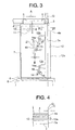
- Fig. 3 is a partial elevation view showing the door device for the elevator at a time when a doorway 1 of Fig. 1 is fully closed.
- Fig. 4 is a sectional view taken along the line IV-IV of Fig. 3 . It should be noted in Fig. 1 that the doorway 1 is in a half-open state.
- an upper portion of the doorway 1 of the elevator is provided with a car-side hanger case 2 fixed to a car, and an elevator hall-side hanger case (not shown) fixed to a wall surface on an elevator hall side.
- the car-side hanger case 2 is provided with a horizontally (in a width direction of the doorway 1) extending car-side door rail 3.
- the elevator hall-side hanger case is provided with a horizontally extending elevator hall-side door rail (not shown) .
- a pair of car doors 4 for opening/closing the doorway 1 are suspended from the car-side door rail 3.
- a plurality of (two in this example) hanger rollers 5, which are laid on the car-side door rail 3, are provided on an upper portion of each of the car doors 4.
- the respective car doors 4 are moved along the car-side door rail 3 due to a driving force of a door driving device (not shown) mounted on the car.
- the respective hanger rollers 5 are rolled on the car-side door rail 3 as the car doors 4 are moved.
- a pair of hall doors 7 for opening/closing the doorway 1 are suspended from the elevator hall-side door rail.
- the respective hall doors 7 are movable along the elevator hall-side door rail.
- the respective hall doors 7 are constantly urged in such a direction as to close the doorway 1 (in a door-closing direction) by weights or springs (not shown).
- a lower portion of the doorway 1 is provided with a car threshold 6 fixed to the car, and an elevator hall threshold 8 fixed to the wall surface on the elevator hall side.
- the car threshold 6 is provided with guide grooves (not shown) into which lower portions of the car doors 4 are inserted, respectively.
- the elevator hall threshold 8 is provided with guide grooves (not shown) into which lower portions of the hall doors 7 are inserted, respectively.
- Each of the car doors 4 and a corresponding one of the hall doors 7 are disposed in parallel to each other in a depth direction of the car ( Figs. 2 and 4 ).
- An engagement device 11 for engaging the car door 4 and the hall door 7 with each other in the width direction of the doorway 1 is provided between the car door 4 and the hall door 7.
- the engagement device 11 has an engagement roller 10 provided on the hall door 7, and a vane 9 fixed to the car door 4.
- the vane 9 can be engaged with the engagement roller 10.
- the vane 9 is a vertically extending plate member.
- the engagement roller 10 is a roller rotatable about a horizontal shaft extending in the depth direction of the car.
- the engagement roller 10 is disposed on the vane 9 on a door-opening side thereof.
- the car door 4 is displaceable between a door juxtaposition position ( Fig. 3 ) at which the car door 4 is juxtaposed to the hall door 7 in the depth direction of the car, and a door deviation position ( Fig. 1 ) at which the car door 4 deviates from the door juxtaposition position toward the door-opening side by a predetermined distance A with respect to the hall door 7.
- a door closing-side end 4a of the car door 4 is disposed at the same position as a door closing-side end 7a of the hall door 7 in the depth direction of the car.
- An elevator door for opening/closing the doorway 1 has the respective car doors 4 and the respective hall doors 7.
- the door closing-side ends 4a of the respective car doors 4 abut on each other, and the door closing-side ends 7a of the respective hall doors 7 abut on each other, at a fully closed door end position O located at a center of the doorway 1 ( Fig. 3 ).
- each of the car doors 4 is displaceable between the door juxtaposition position and the door deviation position with respect to a corresponding one of the hall doors 7 ( Figs. 3 and 4 ).
- a movement of the car door 4 in a door opening direction causes the hall door 7 to move together with the car door 4 in the door opening direction against the urging in a door closing direction by the weight or the like.
- An actuating strip 12 displaceable with respect to the elevator door, and a displacement device 21 for displacing the actuating strip 12 in accordance with displacement of the car door 4 with respect to the hall door 7 are provided between the car door 4 and the hall door 7.
- the actuating strip 12 is a lightweight plate member extending in a height direction of the elevator door. An upper portion and a lower portion of the actuating strip 12 are provided with an upper mounting portion 12b and a lower mounting portion 12c, which protrude toward the door opening side, respectively.
- the actuating strip 12 is displaceable between a protruding position ( Figs. 3 and 4 ) at which the actuating strip 12 protrudes from the door closing-side end of the elevator door in the door closing direction, and a retracted position ( Figs. 1 and 2 ) at which the actuating strip 12 is accommodated between the car door 4 and the hall door 7.
- the retracted position is located on the door opening side with respect to the protruding position. That is, when the actuating strip 12 is located at the protruding position, a door closing-side end 12a of the actuating strip 12 is located on the door closing side with respect to both the door closing-side end 4a of the car door 4 and the door closing-side end 7a of the hall door 7.
- the door closing-side end 12a of the actuating strip 12 is located on the door opening side with respect to at least one of the door closing-side end 4a of the car door 4 and the door closing-side end 7a of the hall door 7.
- the actuating strip 12 is allowed to protrude from the door closing-side end of the elevator door by a protrusion amount C when being located at the protruding position ( Fig. 4 ).
- the car door 4 is provided with an upper turning shaft 13 and a lower turning shaft 14, which are disposed apart from each other in the height direction of the elevator door.
- the actuating strip 12 is supported by the car door 4 via an upper turning link (turning member) 15 turnable about the upper turning shaft 13, and a lower turning link 16 turnable about the lower turning shaft 14.
- the upper mounting portion 12b is turnably mounted at one end of the upper turning link 15 by means of a pin 15a.
- the lower mounting portion 12c is turnably mounted at one end of the lower turning link 16 by means of a pin 16a.
- the actuating strip 12 is displaced between the protruding position and the retracted position through the turning of each of the upper turning link 15 and the lower turning link 16.
- the car door 4 is provided with a stopper 20 for holding the actuating strip 12 at the protruding position through abutment on the upper turning link 15.
- a cam roller 17 is provided at the other end of the upper turning link 15.
- the hall door 7 is provided with a cam plate 18 for turning the upper turning link 15 while coming into contact with the cam roller 17.
- the cam plate 18 is disposed on the door opening side of the cam roller 17.
- the displacement device 21 has the upper turning link 15, the cam roller 17, and the cam plate 18.
- the actuating strip 12 When the car door 4 is located at the door juxtaposition position, the actuating strip 12 is displaced to the protruding position ( Fig. 3 ). When the actuating strip 12 is located at the protruding position, the cam roller 17 is spaced apart from the cam plate 18 by a gap B, and the upper turning link 15 abuts on the stopper 20. The gap B is smaller than the gap A between the vane 9 and the engagement roller 10.
- the actuating strip 12 When the car door 4 is located at the door deviation position, the actuating strip 12 is displaced to the retracted position ( Fig. 1 ). When the actuating strip 12 is located at the retracted position, the turning of the upper turning link 15 is retained while the cam roller 17 remains pressed against the cam plate 18. That is, the cam plate 18 receives the turning of the upper turning link 15 resulting from the weight of the actuating strip 12 itself, so the actuating strip 12 is held at the retracted position.
- the upper turning link 15 When the car door 4 is displaced from the door deviation position to the door juxtaposition position, the upper turning link 15 is turned toward the stopper 20 side while the cam roller 17 comes into contact with the cam plate 18, due to the weight of the actuating strip 12 itself. After that, when the upper turning link 15 abuts on the stopper 20, the upper turning link 15 is stopped from turning, so the actuating strip 12 is held at the protruding position. After that, the cam roller 17 is spaced apart from the cam plate 18, so the car door 4 is displaced to the door juxtaposition position.
- the car door 4 is provided with a micro switch (position detecting device) 19 for detecting whether or not the actuating strip 12 has been displaced to the protruding position.
- the micro switch 19 detects whether or not the actuating strip 12 has been displaced to the protruding position depending on whether or not the micro switch 19 has come into contact with the lower turning link 16.
- the doorway 1 is provided with a full closure detecting sensor (not shown) for detecting whether or not the doorway 1 has been fully closed.
- Information from the full closure detecting sensor and the micro switch 19 is transmitted to a control device for controlling an operation of the elevator.
- the control device controls the operation of the elevator based on information from the full closure detecting sensor and the micro switch 19. That is, only when the elevator door fully closes the doorway 1 and the actuating strip 12 is located at the protruding position, the control device controls the operation of the elevator to allow the car to move.
- the control device moves the elevator door in the door opening direction.
- the control device stops the car from moving.
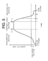
- Fig. 5 is a graph showing a relationship between a speed of the elevator door and a time during a shift in the state of the doorway 1 of Fig. 1 from a fully open state to a fully closed state.
- the speed of the elevator door rises in an acceleration section, becomes constant in a constant-speed section, and then decreases in a deceleration section during the shift in the state of the doorway 1 from the fully open state to the fully closed state.
- the speed of the elevator door rises from 0 gently and then drastically.
- the speed of the elevator door decreases from a speed in the constant-speed section drastically and then gently, and becomes 0 when the doorway 1 is fully closed.
- a range equal to or lower than the speed of the elevator door during a changeover from a great change in speed to a gentle change in speed is defined as a low-speed range.
- the low-speed range is set to a range equal to or lower than 20 mm/s .
- Fig. 6A is a plan view showing the door device for the elevator at a time (in a state at a time t1) when the speed of the elevator door decreases drastically in the deceleration section of Fig. 5 .
- Fig. 6B is a plan view showing the door device for the elevator at a time (in a state at a time t2) when the speed of the elevator door decreases gently in the deceleration section of Fig. 5 .
- Fig. 6C is a plan view showing the door device for the elevator at a time (in a state at a time t3) when the speed of the elevator door is 0 in the deceleration section of Fig. 5 .
- the hall door 7 is also moved in the door closing direction while being engaged with the car door 4.
- each of the hall doors 7 is stopped from moving in the door closing direction and only a corresponding one of the car doors 4 continues to be moved in the door closing direction due to the driving force of the door driving device, as shown in Fig. 6B . That is, the car door 4 is displaced from the door deviation position toward the door juxtaposition position with respect to the hall door 7. At this moment, the vane 9 is disengaged from the engagement roller 10.
- the upper turning link 15 is turned while the cam roller 17 comes into contact with the cam plate 18, so the actuating strip 12 is displaced from the retracted position toward the protruding position.
- the upper turning link 15 abuts on the stopper 20 and then is stopped from turning. After that, the car door 4 continues to be moved in the door closing direction, so the cam roller 17 is spaced apart from the cam plate 18. After that, the car door 4 reaches the door juxtaposition position, so the doorway 1 is fully closed by the elevator door ( Fig. 6C ).
- the car door 4 when the hall doors 7 fully closes the doorway 1, the car door 4 is displaced between the door juxtaposition position and the door deviation position.
- the actuating strip 12 When the car door 4 is located at the door juxtaposition position, the actuating strip 12 is displaced to the protruding position.
- the actuating strip 12 When the car door 4 is located at the door deviation position, the actuating strip 12 is displaced to the retracted position. Therefore, the actuating strip 12 is usually accommodated between the car door 4 and the hall door 7, and can be allowed to protrude from the door closing-side end of each of the doors constituting the elevator door only immediately before the elevator door fully closes the doorway 1.
- a dolly or the like can be prevented from colliding with the actuating strip 12, and the actuating strip 12 can be reduced in strength and weight. Accordingly, even a lightweight and flexible foreign object such as a string can be detected more reliably with a simple construction.
- the displacement device 21 for displacing the actuating strip 12 has the cam plate 18 provided on the hall door 7, and the upper turning link 15 which is turned with respect to the car door 4 while being pressed by the cam plate 18 in accordance with displacement of the car door 4 with respect to the hall door 7. Therefore, displacement of the actuating strip 12 with respect to each of the doors constituting the elevator door can be performed together with displacement of the car door 4 with respect to the hall door 7 with a simple construction.
- the micro switch 19 detects whether or not the actuating strip 12 has been displaced to the protruding position, and the operation of the elevator is controlled based on information from the micro switch 19. Therefore, the elevator door can be restrained from malfunctioning.
- the control device moves each of the doors constituting the elevator door in the door opening direction. Therefore, when a flexible foreign obj ect such as a string is wedged between the doors constituting the elevator door while extending across a space between the elevator hall and the car, the car can be prevented from starting to move.
- the control device stops the car from moving. Therefore, even when the movement of the car is started while a flexible foreign object such as a string extends across a space between the elevator hall and the interior of the car, the car can be stopped immediately through displacement of the actuating strip 12.
- the protrusion amount C of the actuating strip 12 at the time when the actuating strip 12 is located at the protruding position is adjusted by adjusting a length of a section of the upper turning link 15 between the upper turning shaft 13 and the pin 15a and a length of a section of the upper turning link 15 between the upper turning shaft 13 and the cam roller 17.
- Fig. 7 is an enlarged view showing an essential part of a door device for an elevator according to Embodiment 2 of the present invention.
- Fig. 8 is an enlarged view showing the essential part in a state in which an actuating strip-side link member 32 of Fig. 7 has been turned with respect to a cam plate-side link member 33.
- an upper turning link 31 has the actuating strip-side link member 32 and the cam plate-side link member 33, which are turnable about the common upper turning shaft 13.
- One end of the actuating strip-side link member 32 is provided on the upper turning shaft 13.
- the upper mounting portion 12b is turnably mounted at the other end of the actuating strip-side link member 32 by means of the pin 15a.
- a support member 34 extending in a length direction of the cam plate-side link member 33 is provided at one end of the cam plate-side link member 33.
- the support member 34 restricts the turning of the actuating strip-side link member 32 with respect to the cam plate-side link member 33 during displacement of the actuating strip 12 in the door closing direction.
- the cam roller 17 is provided at the other end of the cam plate-side link member 33.
- the cam plate-side link member 33 is turned about the upper turning shaft 13 while being pressed by the cam plate 18.
- the actuating strip-side link member 32 is urged toward the support member 34 side due to the weight of the actuating strip 12.
- the actuating strip-side link member 32 is turned about the upper turning shaft 13 as the cam plate-side link member 33 is turned.
- the actuating strip-side linkmember 32 is turned with respect to the camplate-side link member 33 against the urging by the urging strip 12 when the actuating strip 12 is raised through, for example, contact with a foreign object or the like.
- a micro switch (turning detecting device) 35 for detecting whether or not the actuating strip-side link member 32 has been turned with respect to the cam plate-side link member 33 is provided between the actuating strip-side link member 32 and the support member 34.
- the micro switch 35 is fixed to the actuating strip-side link member 32. Accordingly, when the actuating strip-side link member 32 is turned with respect to the cam plate-side link member 33, the micro switch 35 is displaced so as to be brought into contact with or spaced away from the support member 34.
- the micro switch 35 is activated while being pressed against the support member 34 ( Fig. 7 ).
- the micro switch 35 is deactivated through displacement thereof in such a direction as to be spaced apart from the support member 34 ( Fig. 8).
- Fig. 8 shows a state in which the micro switch 35 has been deactivated with the actuating strip-side link member 32 and the support member 34 forming an angle D therebetween.
- the control device determines whether or not the actuating strip-side link member 32 has been turned with respect to the cam plate-side link member 33 depending on whether or not the micro switch 35 has been activated. That is, when the micro switch 35 is activated, the control device determines that the actuating strip-side link member 32 has not been turned with respect to the cam plate-side link member 33. When the micro switch 35 is deactivated, the control device determines that the actuating strip-side link member 32 has been turned with respect to the cam plate-side link member 33. When the micro switch 35 is deactivated, the control device detects that a foreign obj ect has come into contact with the actuating strip 12.
- Embodiment 2 of the present invention is identical to Embodiment 1 of the present invention in other constructional details.
- the upper turning link 31 has the cam plate-side link member 33, which is turnable with respect to the car door 4 while being pressed by the cam plate 18, and the actuating strip-side link member 32, which is provided with the actuating strip 12 and designed to be turnable with respect to the cam plate-side link member 33.
- the cam plate-side link member 33 is provided with the support member 34 for restricting the turning of the actuating strip-side link member 32 with respect to the cam plate-side link member 33 during displacement of the actuating strip 12 in the door closing direction.
- the micro switch 35 for detecting whether or not the actuating strip-side link member 32 has turned with respect to the cam plate-side link member 33 is provided between the actuating strip-side link member 32 and the support member 34. Therefore, contact of the foreign object with the actuating strip 12 can be detected before the actuating strip 12 reaches the protruding position. Accordingly, the foreign object can be detected earlier.
- Fig. 9 is a partial elevation view showing a door device for an elevator according to Embodiment 3 of the present invention.
- Fig. 10 is a sectional view taken along the line X-X of Fig. 9 .
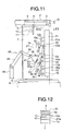
- Fig. 11 is a partial elevation view showing the door device for the elevator at a time when the doorway 1 of Fig. 9 is fully closed.
- Fig. 12 is a sectional view taken along the line XII-XII of Fig. 11 .
- each of the doors constituting the elevator door is provided with a safety shoe 41 displaceable with respect to the car door 4.
- the safety shoe 41 is disposed between the actuating strip 12 and the hall door 7 in the depth direction of the car. In this example, there is a gap E between the car door 4 and the actuating strip 12.
- the car door 4 is provided with a support shaft 42.
- the support shaft 42 is disposed between the upper turning shaft 13 and the lower turning shaft 14 in the height direction of the elevator door.
- the safety shoe 41 is supported by the car door 4 via a turning link 43, which is turnable about the support shaft 42.
- the safety shoe 41 is provided at one end of the turning link 43 turnably about a pin 43a.
- a micro switch (detection device) 55 for detecting whether or not a foreign object has come into contact with the safety shoe 41 is provided at the other end of the turning link 43 through an intermediation of a mounting board 54.
- the car is mounted with a link turning device 45 for turning the turning link 43.
- the link turning device 45 turns the turning link 43 as the car door 4 moves with respect to the car.
- the link turning device 45 has a cam turning body 47 turnable about a support shaft 46 provided on the car door 4, a vertically extending support member 48 provided on the car, and a coupling body 49 for coupling the cam turning body 47 and the support member 48 to each other.
- the cam turning body 47 has a turning portion 50 provided on the support shaft 46, and a cam portion 51 fixed to an end of the turning portion 50 on the turning link 43 side.
- the coupling body 49 is provided so as to be turnable at each of an upper end of the support member 48 and an end of the turning portion 50 on a side opposite to the cam portion 51 side.
- the cam turning body 47 is turned about the support shaft 46 as the car door 4 moves in the width direction.
- the micro switch 55 is thereby displaced toward the cam portion 51.
- the micro switch 55 is thereby displaced away from the cam portion 51.
- a turning press member 44 turnable about a pin 44a is provided on a section of the turning link 43 between the pin 43a and the support shaft 42.
- a free end of the turning press member 44 is disposed between the other end of the turning link 43 and the cam portion 51.
- a cam follower 52 which comes into contact with the cam portion 51 and a seat plate 53 which comes into contact with the micro switch 55 are provided at the free end of the turning press member 44.
- the cam follower 52 is turnable about a rotational shaft 52a.
- Displacement of the safety shoe 41 in such a direction as to protrude from the elevator door is restricted through contact of the cam turning body 47 with the cam follower 52.
- the amount of protrusion of the safety shoe 41 from the elevator door changes as the car door 4 moves in the width direction.
- the safety shoe 41 is accommodated by the doors constituting the elevator door.
- the safety shoe 41 is allowed to protrude from the elevator door as the elevator door is moved in the door opening direction.
- the control device When the micro switch 55 is pressed to be activated, the control device performs the control of normal opening/closing operations. When the micro switch 55 is deactivated, the control device performs the control of reversing the moving direction of the elevator door from the door closing direction to the door opening direction.
- Embodiment 3 of the present invention is identical to Embodiment 1 of the present invention in other constructional details.
- the operation of the safety shoe 41 will be described.
- the cam turning body 47 is turned as the elevator door moves.
- the turning link 43 is turned, so the safety shoe 41 is displaced.
- the micro switch 55 is constantly pressed against the cam portion 51 through an intermediation of the turning press member 44 due to the weight of the safety shoe 41 itself.
- the micro switch 55 remains activated, so the normal opening/closing operation is continued.
- the micro switch 55 When the safety shoe 41 is displaced through contact of, for example, a passenger or the like with the safety shoe 41, the micro switch 55 is displaced away from the turning press member 4 4 through the turning of the turning link 43. Thus, the micro switch 55 is deactivated, so the moving direction of the elevator door is reversed from the door closing direction to the door opening direction.
- the actuating strip 12 operates in the same manner as in Embodiment 1 of the present invention.
- each of the doors constituting the elevator door is provided with the safety shoe 41 in addition to the actuating strip 12. Therefore, not only a lightweight and flexible thing such as a string but also a foreign object exerting a large contact force such as a passenger can be detected more reliably. Thus, different kinds of foreign objects can be detected more reliably.
- the actuating strip 12 is disposed between the safety shoe 41 and the car door 4, so the actuating strip 12 and the car door 4 can be disposed close to each other in the depth direction of the car.
- a string or the like is wedged between the doors constituting the elevator door for fully closing the doorway 1
- a winding angle of the string with respect to the actuating strip 12 can be increased.
- a larger tensile force can be imparted to a foreign object such as the string, so the foreign object can be detected more reliably.
- Fig. 13 is a partial elevation view showing a door device for an elevator according to Embodiment 4 of the present invention.
- Fig. 14 is a sectional view taken along the line XIV-XIV of Fig. 13 .
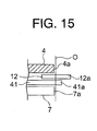
- Fig. 15 is a sectional view showing an essential part of the door device for the elevator at a time when the doorway 1 of Fig. 14 is fully closed.
- the car door 4 is provided with the support shaft 42.
- the safety shoe 41 is supported by the car door 4 via the turning link 43, which is turnable about the support shaft 42.
- a fixed shaft 62 which is disposed apart from the support shaft 42, is fixed to the car door 4.
- a fixed press member 61 is fixed between the support shaft 42 and the fixed shaft 62.
- the fixed press member 61 is provided with the seat plate 53 with which the micro switch 55 comes into contact.
- the safety shoe 41 When the elevator door is moved in the width direction of the doorway 1, the safety shoe 41 remains protruding from the door closing-side end of the elevator door.
- the turning link 43 is urged in such a direction that the micro switch 55 is pressed against the seat plate 53, due to the weight of the safety shoe 41 itself.
- the micro switch 55 By being pressed against the seat plate 53 by the turning link 43, the micro switch 55 is activated.
- the safety shoe 41 is displaced against its own weight, the micro switch 55 is displaced away from the seat plate 53.
- the micro switch 55 is deactivated through its displacement away from the seat plate 53.
- Embodiment 4 of the present invention is identical to Embodiment 3 of the present invention in other constructional details and other operational details.
- the present invention is applied to a biparting door device in which an elevator door composed of doors is designed to open toward both sides so that the doors are separated at a center to be spaced apart from each other.
- the present invention may also be applied to a single swing door device in which an elevator door composed of doors is designed to open only in one direction.
Abstract
An elevator door has a hall door and a car door. The car door is displaceable between a door juxtaposition position at which the car door is juxtaposed to the hall door and a door deviation position at which the car door is located on a door opening side with respect to the hall door by a predetermined distance from the door juxtaposition position. When the car door is located at the door deviation position, the hall door and the car door are moved in engagement with each other. An actuating strip is provided between the car door and the hall door. The actuating strip is displaceable between a protruding position at which the actuating strip protrudes in a door closing direction from a door closing-side end of the elevator door and a retracted position at which the actuating strip is accommodated between the car door and the hall door. The retracted position is located on the door opening side with respect to the protruding position. When the hall door fully closes a doorway, the car door is displaced between the door juxtaposition position and the door deviation position. When the car door is located at the door juxtaposition position, a displacement device displaces the actuating strip to the protruding position. When the car door is located at the door deviation position, the displacement device displaces the actuating strip to the retracted position.
Description
- The present invention relates to a door device for an elevator for opening/closing an elevator doorway which communicates an interior of a car and an elevator hall.
- In a conventional door device for an elevator, with a view to detecting that a foreign object (obstruction) is wedged between a pair of doors, an actuating strip displaceable with respect to each of the doors is provided at a door closing-side end of the door. The actuating strip moves together with the door while remaining protruding from the door closing-side end of the door. When the actuating strip comes into contact with the foreign object and is then displaced with respect to the door, a moving direction of the door is reversed from a door closing direction to a door opening direction (see Patent Document 1).
- Patent Document 1:
JP 05-301692 A - In the conventional door device for the elevator constructed as described above, when the door is moved, the actuating strip remains protruding from the door. Therefore, for example, a dolly or the like tends to hit the actuating strip, so the actuating strip is likely to be damaged. For this reason, the actuating strip is increased in rigidity and weight in order to prevent the actuating strip from being broken. Accordingly, in a case where the foreign object is a flexible and lightweight thing such as a string, the actuating strip is unlikely to be displaced with respect to the door even when the foreign object has come into contact with the actuating strip. As a result, detection of the foreign object may become impossible.
- The present invention has been made to solve the above-mentioned problem, and it is therefore an object of the present invention to obtain a door device for an elevator which makes it possible to detect a foreign object more reliably with a simple construction.
- A door device for an elevator according to the present invention, includes: an elevator door having a hall door and a car door, which is displaceable between a door juxtaposition position at which the car door is juxtaposed to the hall door and a door deviation position at which the car door is located on a door opening side with respect to the hall door by a predetermined distance from the door juxtaposition position, for opening/closing a doorway of the elevator by causing the hall door and the car door to move in engagement with each other when the car door is located at the door deviation position; an actuating strip provided between the car door and the hall door and designed to be displaceable between a protruding position at which the actuating strip protrudes in a door closing direction from a door closing-side end of the elevator door and a retracted position at which the actuating strip is accommodated between the car door and the hall door, the retracted position being located on the door opening side with respect to the protruding position; and a displacement device for displacing the actuating strip in accordance with displacement of the car door with respect to the hall door, in which: the car door is displaced between the door juxtaposition position and the door deviation position when the hall door fully closes the doorway; and the displacement device displaces the actuating strip to the protruding position when the car door is located at the door juxtaposition position, and displaces the actuating strip to the retracted position when the car door is located at the door deviation position.
-
-
Fig. 1 is a partial elevation view showing a door device for an elevator according toEmbodiment 1 of the present invention. -
Fig. 2 is a sectional view taken along the line II-II ofFig. 1 . -
Fig. 3 is a partial elevation view showing the door device for the elevator at a time when a doorway ofFig. 1 is fully closed. -
Fig. 4 is a sectional view taken along the line IV-IV ofFig. 3 . -
Fig. 5 is a graph showing a relationship between a speed of an elevator door and a time during a shift in a state of the doorway ofFig. 1 from a fully open state to a fully closed state. -
Fig. 6A is a plan view showing the door device for the elevator at a time when the speed of the elevator door is falling drastically in a deceleration section ofFig. 5 . -
Fig. 6B is a plan view showing the door device for the elevator at a time when the speed of the elevator door is falling gently in the deceleration section ofFig. 5 . -
Fig. 6C is a plan view showing the door device for the elevator at a time when the speed of the elevator door is 0 in the deceleration section ofFig. 5 . -
Fig. 7 is an enlarged view showing an essential part of a door device for an elevator according toEmbodiment 2 of the present invention. -
Fig. 8 is an enlarged view showing the essential part in a state in which an actuating strip-side link member ofFig. 7 has been turned with respect to a cam plate-side link member. -
Fig. 9 is a partial elevation view showing a door device for an elevator according toEmbodiment 3 of the present invention. -
Fig. 10 is a sectional view taken along the line X-X ofFig. 9 . -
Fig. 11 is a partial elevation view showing the door device for the elevator at a time when a doorway ofFig. 9 is fully closed. -
Fig. 12 is a sectional view taken along the line XII-XII ofFig. 11 . -
Fig. 13 is a partial elevation view showing a door device for an elevator according toEmbodiment 4 of the present invention. -
Fig. 14 is a sectional view taken along the line XIV-XIV ofFig. 13 . -
Fig. 15 is a sectional view showing an essential part of the door device for the elevator at a time when a doorway ofFig. 14 is fully closed. - Preferred embodiments of the present invention will be described hereinafter with reference to the drawings.
-
Fig. 1 is a partial elevation view showing a door device for an elevator according toEmbodiment 1 of the present invention.Fig. 2 is a sectional view taken along the line II-II ofFig. 1 .Fig. 3 is a partial elevation view showing the door device for the elevator at a time when adoorway 1 ofFig. 1 is fully closed.Fig. 4 is a sectional view taken along the line IV-IV ofFig. 3 . It should be noted inFig. 1 that thedoorway 1 is in a half-open state. Referring to the figures, an upper portion of thedoorway 1 of the elevator is provided with a car-side hanger case 2 fixed to a car, and an elevator hall-side hanger case (not shown) fixed to a wall surface on an elevator hall side. The car-side hanger case 2 is provided with a horizontally (in a width direction of the doorway 1) extending car-side door rail 3. The elevator hall-side hanger case is provided with a horizontally extending elevator hall-side door rail (not shown) . - A pair of
car doors 4 for opening/closing thedoorway 1 are suspended from the car-side door rail 3. A plurality of (two in this example)hanger rollers 5, which are laid on the car-side door rail 3, are provided on an upper portion of each of thecar doors 4. Therespective car doors 4 are moved along the car-side door rail 3 due to a driving force of a door driving device (not shown) mounted on the car. Therespective hanger rollers 5 are rolled on the car-side door rail 3 as thecar doors 4 are moved. - A pair of
hall doors 7 for opening/closing thedoorway 1 are suspended from the elevator hall-side door rail. Therespective hall doors 7 are movable along the elevator hall-side door rail. Therespective hall doors 7 are constantly urged in such a direction as to close the doorway 1 (in a door-closing direction) by weights or springs (not shown). - A lower portion of the
doorway 1 is provided with acar threshold 6 fixed to the car, and anelevator hall threshold 8 fixed to the wall surface on the elevator hall side. Thecar threshold 6 is provided with guide grooves (not shown) into which lower portions of thecar doors 4 are inserted, respectively. Theelevator hall threshold 8 is provided with guide grooves (not shown) into which lower portions of thehall doors 7 are inserted, respectively. - Each of the
car doors 4 and a corresponding one of thehall doors 7 are disposed in parallel to each other in a depth direction of the car (Figs. 2 and4 ). Anengagement device 11 for engaging thecar door 4 and thehall door 7 with each other in the width direction of thedoorway 1 is provided between thecar door 4 and thehall door 7. Theengagement device 11 has anengagement roller 10 provided on thehall door 7, and avane 9 fixed to thecar door 4. Thevane 9 can be engaged with theengagement roller 10. Thevane 9 is a vertically extending plate member. Theengagement roller 10 is a roller rotatable about a horizontal shaft extending in the depth direction of the car. In addition, theengagement roller 10 is disposed on thevane 9 on a door-opening side thereof. - The
car door 4 is displaceable between a door juxtaposition position (Fig. 3 ) at which thecar door 4 is juxtaposed to thehall door 7 in the depth direction of the car, and a door deviation position (Fig. 1 ) at which thecar door 4 deviates from the door juxtaposition position toward the door-opening side by a predetermined distance A with respect to thehall door 7. When thecar door 4 is located at the door deviation position, thevane 9 is engaged with theengagement roller 10. When thecar door 4 is located at the door juxtaposition position, a door closing-side end 4a of thecar door 4 is disposed at the same position as a door closing-side end 7a of thehall door 7 in the depth direction of the car. - An elevator door for opening/closing the
doorway 1 has therespective car doors 4 and therespective hall doors 7. When the elevator door fully closes thedoorway 1, the door closing-side ends 4a of therespective car doors 4 abut on each other, and the door closing-side ends 7a of therespective hall doors 7 abut on each other, at a fully closed door end position O located at a center of the doorway 1 (Fig. 3 ). - When the
respective hall doors 7 fully closes thedoorway 1, each of thecar doors 4 is displaceable between the door juxtaposition position and the door deviation position with respect to a corresponding one of the hall doors 7 (Figs. 3 and 4 ). When thehall door 7 is engaged with thecar door 4, a movement of thecar door 4 in a door opening direction causes thehall door 7 to move together with thecar door 4 in the door opening direction against the urging in a door closing direction by the weight or the like. Furthermore, when thehall door 7 is engaged with thecar door 4, a movement of thecar door 4 in the door closing direction causes thehall door 7 to move in the door closing direction in accordance with the movement of thecar door 4 without being disengaged from thecar door 4 due to the urging in the door closing direction by the weight or the like. - An
actuating strip 12 displaceable with respect to the elevator door, and adisplacement device 21 for displacing theactuating strip 12 in accordance with displacement of thecar door 4 with respect to thehall door 7 are provided between thecar door 4 and thehall door 7. - The
actuating strip 12 is a lightweight plate member extending in a height direction of the elevator door. An upper portion and a lower portion of theactuating strip 12 are provided with an upper mountingportion 12b and alower mounting portion 12c, which protrude toward the door opening side, respectively. - The
actuating strip 12 is displaceable between a protruding position (Figs. 3 and 4 ) at which theactuating strip 12 protrudes from the door closing-side end of the elevator door in the door closing direction, and a retracted position (Figs. 1 and 2 ) at which theactuating strip 12 is accommodated between thecar door 4 and thehall door 7. The retracted position is located on the door opening side with respect to the protruding position. That is, when theactuating strip 12 is located at the protruding position, a door closing-side end 12a of theactuating strip 12 is located on the door closing side with respect to both the door closing-side end 4a of thecar door 4 and the door closing-side end 7a of thehall door 7. When theactuating strip 12 is located at the retracted position, the door closing-side end 12a of theactuating strip 12 is located on the door opening side with respect to at least one of the door closing-side end 4a of thecar door 4 and the door closing-side end 7a of thehall door 7. In this example, theactuating strip 12 is allowed to protrude from the door closing-side end of the elevator door by a protrusion amount C when being located at the protruding position (Fig. 4 ). - The
car door 4 is provided with anupper turning shaft 13 and alower turning shaft 14, which are disposed apart from each other in the height direction of the elevator door. Theactuating strip 12 is supported by thecar door 4 via an upper turning link (turning member) 15 turnable about theupper turning shaft 13, and alower turning link 16 turnable about thelower turning shaft 14. The upper mountingportion 12b is turnably mounted at one end of theupper turning link 15 by means of apin 15a. Thelower mounting portion 12c is turnably mounted at one end of thelower turning link 16 by means of apin 16a. Theactuating strip 12 is displaced between the protruding position and the retracted position through the turning of each of theupper turning link 15 and thelower turning link 16. Thecar door 4 is provided with astopper 20 for holding theactuating strip 12 at the protruding position through abutment on theupper turning link 15. - A
cam roller 17 is provided at the other end of theupper turning link 15. Thehall door 7 is provided with acam plate 18 for turning theupper turning link 15 while coming into contact with thecam roller 17. Thecam plate 18 is disposed on the door opening side of thecam roller 17. Thedisplacement device 21 has theupper turning link 15, thecam roller 17, and thecam plate 18. - When the
car door 4 is located at the door juxtaposition position, theactuating strip 12 is displaced to the protruding position (Fig. 3 ). When theactuating strip 12 is located at the protruding position, thecam roller 17 is spaced apart from thecam plate 18 by a gap B, and theupper turning link 15 abuts on thestopper 20. The gap B is smaller than the gap A between thevane 9 and theengagement roller 10. - When the
car door 4 is located at the door deviation position, theactuating strip 12 is displaced to the retracted position (Fig. 1 ). When theactuating strip 12 is located at the retracted position, the turning of theupper turning link 15 is retained while thecam roller 17 remains pressed against thecam plate 18. That is, thecam plate 18 receives the turning of theupper turning link 15 resulting from the weight of theactuating strip 12 itself, so theactuating strip 12 is held at the retracted position. - When the
car door 4 is displaced from the door juxtaposition position to the door deviation position, thecam roller 17 comes into contact with thecam plate 18 before thevane 9 is engaged with theengagement roller 10. After that as well, when thecar door 4 is displaced toward the door deviation position, theupper turning link 15 is turned while thecam roller 17 is pressed by thecam plate 18, so thevane 9 is engaged with theengagement roller 10. Thus, theactuating strip 12 is displaced to the retracted position. - When the
car door 4 is displaced from the door deviation position to the door juxtaposition position, theupper turning link 15 is turned toward thestopper 20 side while thecam roller 17 comes into contact with thecam plate 18, due to the weight of theactuating strip 12 itself. After that, when theupper turning link 15 abuts on thestopper 20, theupper turning link 15 is stopped from turning, so theactuating strip 12 is held at the protruding position. After that, thecam roller 17 is spaced apart from thecam plate 18, so thecar door 4 is displaced to the door juxtaposition position. - The
car door 4 is provided with a micro switch (position detecting device) 19 for detecting whether or not theactuating strip 12 has been displaced to the protruding position. In this example, themicro switch 19 detects whether or not theactuating strip 12 has been displaced to the protruding position depending on whether or not themicro switch 19 has come into contact with thelower turning link 16. Thedoorway 1 is provided with a full closure detecting sensor (not shown) for detecting whether or not thedoorway 1 has been fully closed. - Information from the full closure detecting sensor and the
micro switch 19 is transmitted to a control device for controlling an operation of the elevator. The control device controls the operation of the elevator based on information from the full closure detecting sensor and themicro switch 19. That is, only when the elevator door fully closes thedoorway 1 and theactuating strip 12 is located at the protruding position, the control device controls the operation of the elevator to allow the car to move. When the elevator door fully closes thedoorway 1 and theactuating strip 12 deviates from the protruding position before start of the movement of the car, the control device moves the elevator door in the door opening direction. In addition, when the elevator door fully closes thedoorway 1 and theactuating strip 12 deviates from the protruding position after the start of the movement of the car, the control device stops the car from moving. -
Fig. 5 is a graph showing a relationship between a speed of the elevator door and a time during a shift in the state of thedoorway 1 ofFig. 1 from a fully open state to a fully closed state. As shown in the figure, the speed of the elevator door rises in an acceleration section, becomes constant in a constant-speed section, and then decreases in a deceleration section during the shift in the state of thedoorway 1 from the fully open state to the fully closed state. - In the acceleration section, the speed of the elevator door rises from 0 gently and then drastically. In the deceleration section, the speed of the elevator door decreases from a speed in the constant-speed section drastically and then gently, and becomes 0 when the
doorway 1 is fully closed. Note that in the deceleration section, a range equal to or lower than the speed of the elevator door during a changeover from a great change in speed to a gentle change in speed is defined as a low-speed range. In this example, the low-speed range is set to a range equal to or lower than 20 mm/s . When the speed of the elevator door is within the low-speed range, therespective hall doors 7 fully closes thedoorway 1, and each of thecar doors 4 is displaceable with respect to a corresponding one of thehall doors 7. - Next, an operation will be described.
Fig. 6A is a plan view showing the door device for the elevator at a time (in a state at a time t1) when the speed of the elevator door decreases drastically in the deceleration section ofFig. 5 .Fig. 6B is a plan view showing the door device for the elevator at a time (in a state at a time t2) when the speed of the elevator door decreases gently in the deceleration section ofFig. 5 . Furthermore,Fig. 6C is a plan view showing the door device for the elevator at a time (in a state at a time t3) when the speed of the elevator door is 0 in the deceleration section ofFig. 5 . - When the
car door 4 is moved in the door closing direction due to a driving force of the door driving device from the fully open state of thedoorway 1, thehall door 7 is also moved in the door closing direction while being engaged with thecar door 4. - For example, when the speed of the elevator door decreases drastically in the deceleration section, the
car door 4 is displaced to the door deviation position and thevane 9 is engaged with theengagement roller 10, as shown inFig. 6A . At this moment, theactuating strip 12 is held at the retracted position while thecam roller 17 is pressed by thecam plate 18. - When the speed of the elevator door enters the low-speed range and the
respective hall doors 7 fully close thedoorway 1, each of thehall doors 7 is stopped from moving in the door closing direction and only a corresponding one of thecar doors 4 continues to be moved in the door closing direction due to the driving force of the door driving device, as shown inFig. 6B . That is, thecar door 4 is displaced from the door deviation position toward the door juxtaposition position with respect to thehall door 7. At this moment, thevane 9 is disengaged from theengagement roller 10. Theupper turning link 15 is turned while thecam roller 17 comes into contact with thecam plate 18, so theactuating strip 12 is displaced from the retracted position toward the protruding position. - After that as well, when the
car door 4 continues to be moved in the door closing direction, theupper turning link 15 abuts on thestopper 20 and then is stopped from turning. After that, thecar door 4 continues to be moved in the door closing direction, so thecam roller 17 is spaced apart from thecam plate 18. After that, thecar door 4 reaches the door juxtaposition position, so thedoorway 1 is fully closed by the elevator door (Fig. 6C ). - When the
doorway 1 is fully closed, thelower turning link 16 comes into contact with themicro switch 19, so it is detected that theactuating strip 12 has reached the protruding position. - After that, when the control device confirms that the
actuating strip 12 has been displaced to the protruding position and that the operation of fully closing thedoorway 1 has been completed, the car is allowed to move. - In opening the elevator door, an operation reverse to the aforementioned operation is performed to engage the
car door 4 with thehall door 7, so theactuating strip 12 is displaced from the protruding position to the retracted position. - Next, an operation performed when a foreign object such as a string is wedged between the doors constituting the elevator door will be described. If there is a foreign object interposed between the doors constituting the elevator door when the elevator door fully closes the
doorway 1, the foreign object prevents theactuating strip 12 from being displaced to the protruding position. Thus, themicro switch 19 is not activated, and the control device detects that theactuating strip 12 deviates from the protruding position. Thus, the operation of opening the elevator door is performed. - Even when the movement of the car is started while the foreign object is wedged between the respective doors constituting the elevator door, a tensile force is applied to the foreign object through the movement of the car, so the
actuating strip 12 deviates from the protruding position. Thus, thelower turning link 16 is spaced apart from themicro switch 19, and the control device detects that theactuating strip 12 deviates from the protruding position. Thus, the car is stopped from moving. - In the door device for the elevator constructed as described above, when the
hall doors 7 fully closes thedoorway 1, thecar door 4 is displaced between the door juxtaposition position and the door deviation position. When thecar door 4 is located at the door juxtaposition position, theactuating strip 12 is displaced to the protruding position. When thecar door 4 is located at the door deviation position, theactuating strip 12 is displaced to the retracted position. Therefore, theactuating strip 12 is usually accommodated between thecar door 4 and thehall door 7, and can be allowed to protrude from the door closing-side end of each of the doors constituting the elevator door only immediately before the elevator door fully closes thedoorway 1. Thus, a dolly or the like can be prevented from colliding with theactuating strip 12, and theactuating strip 12 can be reduced in strength and weight. Accordingly, even a lightweight and flexible foreign object such as a string can be detected more reliably with a simple construction. - The
displacement device 21 for displacing theactuating strip 12 has thecam plate 18 provided on thehall door 7, and theupper turning link 15 which is turned with respect to thecar door 4 while being pressed by thecam plate 18 in accordance with displacement of thecar door 4 with respect to thehall door 7. Therefore, displacement of theactuating strip 12 with respect to each of the doors constituting the elevator door can be performed together with displacement of thecar door 4 with respect to thehall door 7 with a simple construction. - The
micro switch 19 detects whether or not theactuating strip 12 has been displaced to the protruding position, and the operation of the elevator is controlled based on information from themicro switch 19. Therefore, the elevator door can be restrained from malfunctioning. - When the elevator door fully closes the
doorway 1 and theactuating strip 12 deviates from the protruding position before the start of the movement of the car, the control device moves each of the doors constituting the elevator door in the door opening direction. Therefore, when a flexible foreign obj ect such as a string is wedged between the doors constituting the elevator door while extending across a space between the elevator hall and the car, the car can be prevented from starting to move. - When the elevator door fully closes the
doorway 1 and theactuating strip 12 deviates from the protruding position after the start of the movement of the car, the control device stops the car from moving. Therefore, even when the movement of the car is started while a flexible foreign object such as a string extends across a space between the elevator hall and the interior of the car, the car can be stopped immediately through displacement of theactuating strip 12. - The protrusion amount C of the
actuating strip 12 at the time when theactuating strip 12 is located at the protruding position is adjusted by adjusting a length of a section of theupper turning link 15 between theupper turning shaft 13 and thepin 15a and a length of a section of theupper turning link 15 between theupper turning shaft 13 and thecam roller 17. -
Fig. 7 is an enlarged view showing an essential part of a door device for an elevator according toEmbodiment 2 of the present invention.Fig. 8 is an enlarged view showing the essential part in a state in which an actuating strip-side link member 32 ofFig. 7 has been turned with respect to a cam plate-side link member 33. Referring to the figures, anupper turning link 31 has the actuating strip-side link member 32 and the cam plate-side link member 33, which are turnable about the commonupper turning shaft 13. - One end of the actuating strip-
side link member 32 is provided on theupper turning shaft 13. The upper mountingportion 12b is turnably mounted at the other end of the actuating strip-side link member 32 by means of thepin 15a. Asupport member 34 extending in a length direction of the cam plate-side link member 33 is provided at one end of the cam plate-side link member 33. Thesupport member 34 restricts the turning of the actuating strip-side link member 32 with respect to the cam plate-side link member 33 during displacement of theactuating strip 12 in the door closing direction. Moreover, thecam roller 17 is provided at the other end of the cam plate-side link member 33. - The cam plate-
side link member 33 is turned about theupper turning shaft 13 while being pressed by thecam plate 18. The actuating strip-side link member 32 is urged toward thesupport member 34 side due to the weight of theactuating strip 12. Thus, while remaining urged by thesupport member 34, the actuating strip-side link member 32 is turned about theupper turning shaft 13 as the cam plate-side link member 33 is turned. The actuating strip-side linkmember 32 is turned with respect to the camplate-side link member 33 against the urging by the urgingstrip 12 when theactuating strip 12 is raised through, for example, contact with a foreign object or the like. - A micro switch (turning detecting device) 35 for detecting whether or not the actuating strip-
side link member 32 has been turned with respect to the cam plate-side link member 33 is provided between the actuating strip-side link member 32 and thesupport member 34. Themicro switch 35 is fixed to the actuating strip-side link member 32. Accordingly, when the actuating strip-side link member 32 is turned with respect to the cam plate-side link member 33, themicro switch 35 is displaced so as to be brought into contact with or spaced away from thesupport member 34. Themicro switch 35 is activated while being pressed against the support member 34 (Fig. 7 ). Themicro switch 35 is deactivated through displacement thereof in such a direction as to be spaced apart from the support member 34 (Fig. 8). Fig. 8 shows a state in which themicro switch 35 has been deactivated with the actuating strip-side link member 32 and thesupport member 34 forming an angle D therebetween. - The control device determines whether or not the actuating strip-
side link member 32 has been turned with respect to the cam plate-side link member 33 depending on whether or not themicro switch 35 has been activated. That is, when themicro switch 35 is activated, the control device determines that the actuating strip-side link member 32 has not been turned with respect to the cam plate-side link member 33. When themicro switch 35 is deactivated, the control device determines that the actuating strip-side link member 32 has been turned with respect to the cam plate-side link member 33. When themicro switch 35 is deactivated, the control device detects that a foreign obj ect has come into contact with theactuating strip 12.Embodiment 2 of the present invention is identical toEmbodiment 1 of the present invention in other constructional details. - In the door device for the elevator constructed as described above, the
upper turning link 31 has the cam plate-side link member 33, which is turnable with respect to thecar door 4 while being pressed by thecam plate 18, and the actuating strip-side link member 32, which is provided with theactuating strip 12 and designed to be turnable with respect to the cam plate-side link member 33. The cam plate-side link member 33 is provided with thesupport member 34 for restricting the turning of the actuating strip-side link member 32 with respect to the cam plate-side link member 33 during displacement of theactuating strip 12 in the door closing direction. Themicro switch 35 for detecting whether or not the actuating strip-side link member 32 has turned with respect to the cam plate-side link member 33 is provided between the actuating strip-side link member 32 and thesupport member 34. Therefore, contact of the foreign object with theactuating strip 12 can be detected before theactuating strip 12 reaches the protruding position. Accordingly, the foreign object can be detected earlier. -
Fig. 9 is a partial elevation view showing a door device for an elevator according toEmbodiment 3 of the present invention.Fig. 10 is a sectional view taken along the line X-X ofFig. 9 .Fig. 11 is a partial elevation view showing the door device for the elevator at a time when thedoorway 1 ofFig. 9 is fully closed.Fig. 12 is a sectional view taken along the line XII-XII ofFig. 11 . Referring to the figures, each of the doors constituting the elevator door is provided with asafety shoe 41 displaceable with respect to thecar door 4. Thesafety shoe 41 is disposed between the actuatingstrip 12 and thehall door 7 in the depth direction of the car. In this example, there is a gap E between thecar door 4 and theactuating strip 12. - The
car door 4 is provided with asupport shaft 42. Thesupport shaft 42 is disposed between theupper turning shaft 13 and thelower turning shaft 14 in the height direction of the elevator door. Thesafety shoe 41 is supported by thecar door 4 via aturning link 43, which is turnable about thesupport shaft 42. - The
safety shoe 41 is provided at one end of the turninglink 43 turnably about apin 43a. A micro switch (detection device) 55 for detecting whether or not a foreign object has come into contact with thesafety shoe 41 is provided at the other end of the turninglink 43 through an intermediation of a mountingboard 54. - The car is mounted with a
link turning device 45 for turning the turninglink 43. Thelink turning device 45 turns the turninglink 43 as thecar door 4 moves with respect to the car. Thelink turning device 45 has acam turning body 47 turnable about asupport shaft 46 provided on thecar door 4, a vertically extendingsupport member 48 provided on the car, and acoupling body 49 for coupling thecam turning body 47 and thesupport member 48 to each other. - The
cam turning body 47 has a turningportion 50 provided on thesupport shaft 46, and acam portion 51 fixed to an end of the turningportion 50 on the turninglink 43 side. Thecoupling body 49 is provided so as to be turnable at each of an upper end of thesupport member 48 and an end of the turningportion 50 on a side opposite to thecam portion 51 side. Thus, thecam turning body 47 is turned about thesupport shaft 46 as thecar door 4 moves in the width direction. - When the turning
link 43 is turned in such a direction that thesafety shoe 41 protrudes from each of the doors constituting the elevator door, themicro switch 55 is thereby displaced toward thecam portion 51. When the turninglink 43 is turned in such a direction that thesafety shoe 41 is accommodated in the doors constituting the elevator door, themicro switch 55 is thereby displaced away from thecam portion 51. - A turning
press member 44 turnable about apin 44a is provided on a section of the turninglink 43 between thepin 43a and thesupport shaft 42. A free end of the turningpress member 44 is disposed between the other end of the turninglink 43 and thecam portion 51. Acam follower 52 which comes into contact with thecam portion 51 and aseat plate 53 which comes into contact with themicro switch 55 are provided at the free end of the turningpress member 44. Thecam follower 52 is turnable about arotational shaft 52a. - Displacement of the
safety shoe 41 in such a direction as to protrude from the elevator door is restricted through contact of thecam turning body 47 with thecam follower 52. The amount of protrusion of thesafety shoe 41 from the elevator door changes as thecar door 4 moves in the width direction. In this example, when the elevator door fully closes thedoorway 1, thesafety shoe 41 is accommodated by the doors constituting the elevator door. Thesafety shoe 41 is allowed to protrude from the elevator door as the elevator door is moved in the door opening direction. - When the
micro switch 55 is pressed to be activated, the control device performs the control of normal opening/closing operations. When themicro switch 55 is deactivated, the control device performs the control of reversing the moving direction of the elevator door from the door closing direction to the door opening direction. - By being pressed against the
seat plate 53 due to the weight of thesafety shoe 41 itself, themicro switch 55 is activated. When thesafety shoe 41 is displaced in such a direction as to be accommodated in the doors constituting the elevator door against the weight of thesafety shoe 41 itself, themicro switch 55 is thereby deactivated.Embodiment 3 of the present invention is identical toEmbodiment 1 of the present invention in other constructional details. - Next, the operation of the
safety shoe 41 will be described. During the operation of opening/closing the elevator door, thecam turning body 47 is turned as the elevator door moves. Thus, the turninglink 43 is turned, so thesafety shoe 41 is displaced. At this moment, themicro switch 55 is constantly pressed against thecam portion 51 through an intermediation of the turningpress member 44 due to the weight of thesafety shoe 41 itself. Thus, themicro switch 55 remains activated, so the normal opening/closing operation is continued. - When the
safety shoe 41 is displaced through contact of, for example, a passenger or the like with thesafety shoe 41, themicro switch 55 is displaced away from the turningpress member 4 4 through the turning of the turninglink 43. Thus, themicro switch 55 is deactivated, so the moving direction of the elevator door is reversed from the door closing direction to the door opening direction. Theactuating strip 12 operates in the same manner as inEmbodiment 1 of the present invention. - In the door device for the elevator constructed as described above, each of the doors constituting the elevator door is provided with the
safety shoe 41 in addition to theactuating strip 12. Therefore, not only a lightweight and flexible thing such as a string but also a foreign object exerting a large contact force such as a passenger can be detected more reliably. Thus, different kinds of foreign objects can be detected more reliably. - The
actuating strip 12 is disposed between thesafety shoe 41 and thecar door 4, so theactuating strip 12 and thecar door 4 can be disposed close to each other in the depth direction of the car. When, for example, a string or the like is wedged between the doors constituting the elevator door for fully closing thedoorway 1, a winding angle of the string with respect to theactuating strip 12 can be increased. Thus, a larger tensile force can be imparted to a foreign object such as the string, so the foreign object can be detected more reliably. -
Fig. 13 is a partial elevation view showing a door device for an elevator according toEmbodiment 4 of the present invention.Fig. 14 is a sectional view taken along the line XIV-XIV ofFig. 13 .Fig. 15 is a sectional view showing an essential part of the door device for the elevator at a time when thedoorway 1 ofFig. 14 is fully closed. Referring to the figures, thecar door 4 is provided with thesupport shaft 42. Thesafety shoe 41 is supported by thecar door 4 via the turninglink 43, which is turnable about thesupport shaft 42. - A fixed
shaft 62, which is disposed apart from thesupport shaft 42, is fixed to thecar door 4. A fixedpress member 61 is fixed between thesupport shaft 42 and the fixedshaft 62. The fixedpress member 61 is provided with theseat plate 53 with which themicro switch 55 comes into contact. - When the elevator door is moved in the width direction of the
doorway 1, thesafety shoe 41 remains protruding from the door closing-side end of the elevator door. The turninglink 43 is urged in such a direction that themicro switch 55 is pressed against theseat plate 53, due to the weight of thesafety shoe 41 itself. By being pressed against theseat plate 53 by the turninglink 43, themicro switch 55 is activated. When thesafety shoe 41 is displaced against its own weight, themicro switch 55 is displaced away from theseat plate 53. Themicro switch 55 is deactivated through its displacement away from theseat plate 53. - When the
actuating strip 12 is located at the protruding position, the door closing-side end 12a of theactuating strip 12 is located on the door closing side with respect to the safety shoe 41 (Fig. 15 ). When theactuating strip 12 is located at the retracted position, the door closing-side end 12a of theactuating strip 12 is located on the door opening side with respect to the safety shoe 41 (Fig. 14 ).Embodiment 4 of the present invention is identical toEmbodiment 3 of the present invention in other constructional details and other operational details. - In the door device for the elevator constructed as described above, displacement of the
safety shoe 41 with respect to the elevator door and movement of the elevator door in the width direction are made independent of each other instead of being performed together with each other. Therefore, the door device can be further simplified in construction. - In the foregoing examples, the present invention is applied to a biparting door device in which an elevator door composed of doors is designed to open toward both sides so that the doors are separated at a center to be spaced apart from each other. However, the present invention may also be applied to a single swing door device in which an elevator door composed of doors is designed to open only in one direction.
Claims (7)
- A door device for an elevator, comprising:an elevator door having a hall door and a car door, which is displaceable between a door juxtaposition position at which the car door is juxtaposed to the hall door and a door deviation position at which the car door is located on a door opening side with respect to the hall door by a predetermined distance from the door juxtaposition position, for opening and closing a doorway of the elevator by causing the hall door and the car door to move in engagement with each other when the car door is located at the door deviation position;an actuating strip provided between the car door and the hall door and designed to be displaceable between a protruding position at which the actuating strip protrudes in a door closing direction from a door closing-side end of the elevator door and a retracted position at which the actuating strip is accommodated between the car door and the hall door, the retracted position being located on the door opening side with respect to the protruding position; anda displacement device for displacing the actuating strip in accordance with displacement of the car door with respect to the hall door, wherein:the car door is displaced between the door juxtaposition position and the door deviation position when the hall door fully closes the doorway; andthe displacement device displaces the actuating strip to the protruding position when the car door is located at the door juxtaposition position, and displaces the actuating strip to the retracted position when the car door is located at the door deviation position.
- A door device for an elevator according to Claim 1, wherein:the displacement device has a cam plate provided on the hall door, and a turning member provided with the actuating strip and designed to be turned with respect to the car door while remaining in contact with the cam plate through displacement of the car door with respect to the hall door; andthe actuating strip is displaced between the protruding position and the retracted position through turning of the turning member.
- A door device for an elevator according to Claim 1 or 2, further comprising:a position detecting device for detecting whether or not the actuating strip has been displaced to the protruding position; anda control device for controlling operation of the elevator based on information from the position detecting device.
- A door device for an elevator according to Claim 3, wherein the control device moves the elevator door in a door opening direction when the elevator door fully closes the doorway and the actuating strip deviates from the protruding position before start of movement of a car.
- A door device for an elevator according to Claim 3 or 4, wherein the control device stops movement of a car when the elevator door fully closes the doorway and the actuating strip deviates from the protruding position after start of the movement of the car.
- A door device for an elevator according to Claim 2, wherein:the turning member has a cam plate-side link member designed to be turnable with respect to the car door while being pressed by the cam plate, and an actuating strip-side link member provided with the actuating strip and designed to be turnable with respect to the cam plate-side link member;the camplate-side link member is provided with a support member for restricting turning of the actuating strip-side link member with respect to the cam plate-side link member during displacement of the actuating strip in the door closing direction; andthe door device further comprises a turning detecting device for detecting whether or not the actuating strip-side link member has turned with respect to the cam plate-side link member during displacement of the actuating strip in a door opening direction.
- A door device for an elevator according to any one of Claims 1 to 6, wherein between the car door and the hall door, a safety shoe which is displaced in the door opening direction with respect to the elevator door, for detecting presence of a foreign object, is provided separately from the actuating strip.
Applications Claiming Priority (1)
| Application Number | Priority Date | Filing Date | Title |
|---|---|---|---|
| PCT/JP2005/015433 WO2007023549A1 (en) | 2005-08-25 | 2005-08-25 | Door device for elevator |
Publications (2)
| Publication Number | Publication Date |
|---|---|
| EP1918241A1 true EP1918241A1 (en) | 2008-05-07 |
| EP1918241A4 EP1918241A4 (en) | 2013-01-16 |
Family
ID=37771307
Family Applications (1)
| Application Number | Title | Priority Date | Filing Date |
|---|---|---|---|
| EP05780958A Withdrawn EP1918241A4 (en) | 2005-08-25 | 2005-08-25 | Door device for elevator |
Country Status (5)
| Country | Link |
|---|---|
| EP (1) | EP1918241A4 (en) |
| JP (1) | JPWO2007023549A1 (en) |
| KR (1) | KR100940420B1 (en) |
| CN (1) | CN100569623C (en) |
| WO (1) | WO2007023549A1 (en) |
Cited By (2)
| Publication number | Priority date | Publication date | Assignee | Title |
|---|---|---|---|---|
| EP2345618A1 (en) | 2010-01-18 | 2011-07-20 | Inventio AG | Safety edge of a cabin door |
| CN104401860A (en) * | 2014-09-22 | 2015-03-11 | 苏州合欣美电子科技有限公司 | Safe vertical elevator |
Families Citing this family (4)
| Publication number | Priority date | Publication date | Assignee | Title |
|---|---|---|---|---|
| CN101481059B (en) * | 2009-02-12 | 2011-05-25 | 日立电梯(中国)有限公司 | Safety elevator with function for preventing abnormally opened door and safety control method thereof |
| JP2011116493A (en) * | 2009-12-02 | 2011-06-16 | Toshiba Elevator Co Ltd | Cage door device for elevator |
| JP6016338B2 (en) * | 2011-08-10 | 2016-10-26 | 三菱電機株式会社 | Elevator car door safety device |
| JP5978119B2 (en) * | 2012-12-19 | 2016-08-24 | 株式会社日立製作所 | Elevator door equipment |
Citations (4)
| Publication number | Priority date | Publication date | Assignee | Title |
|---|---|---|---|---|
| US3168165A (en) * | 1962-06-11 | 1965-02-02 | Serge Elevator Company Inc | Protective door reversing means |
| GB1227197A (en) * | 1968-10-31 | 1971-04-07 | ||
| WO2001023293A1 (en) * | 1999-09-29 | 2001-04-05 | Hitachi, Ltd. | Elevator device |
| JP2005008383A (en) * | 2003-06-20 | 2005-01-13 | Hitachi Ltd | Elevator device |
Family Cites Families (2)
| Publication number | Priority date | Publication date | Assignee | Title |
|---|---|---|---|---|
| JPH05301692A (en) | 1992-04-27 | 1993-11-16 | Mitsubishi Electric Corp | Safety device for elevator entrance door |
| JP3274575B2 (en) * | 1994-12-19 | 2002-04-15 | 三菱電機ビルテクノサービス株式会社 | Elevator basket door pinch detection device |
-
2005
- 2005-08-25 CN CNB2005800371551A patent/CN100569623C/en not_active Expired - Fee Related
- 2005-08-25 WO PCT/JP2005/015433 patent/WO2007023549A1/en active Application Filing
- 2005-08-25 JP JP2007531992A patent/JPWO2007023549A1/en active Pending
- 2005-08-25 EP EP05780958A patent/EP1918241A4/en not_active Withdrawn
- 2005-08-25 KR KR1020077011398A patent/KR100940420B1/en not_active IP Right Cessation
Patent Citations (4)
| Publication number | Priority date | Publication date | Assignee | Title |
|---|---|---|---|---|
| US3168165A (en) * | 1962-06-11 | 1965-02-02 | Serge Elevator Company Inc | Protective door reversing means |
| GB1227197A (en) * | 1968-10-31 | 1971-04-07 | ||
| WO2001023293A1 (en) * | 1999-09-29 | 2001-04-05 | Hitachi, Ltd. | Elevator device |
| JP2005008383A (en) * | 2003-06-20 | 2005-01-13 | Hitachi Ltd | Elevator device |
Non-Patent Citations (1)
| Title |
|---|
| See also references of WO2007023549A1 * |
Cited By (3)
| Publication number | Priority date | Publication date | Assignee | Title |
|---|---|---|---|---|
| EP2345618A1 (en) | 2010-01-18 | 2011-07-20 | Inventio AG | Safety edge of a cabin door |
| WO2011086062A1 (en) | 2010-01-18 | 2011-07-21 | Inventio Ag | Safety contact strip for a cab door |
| CN104401860A (en) * | 2014-09-22 | 2015-03-11 | 苏州合欣美电子科技有限公司 | Safe vertical elevator |
Also Published As
| Publication number | Publication date |
|---|---|
| KR20070084379A (en) | 2007-08-24 |
| WO2007023549A1 (en) | 2007-03-01 |
| CN101048333A (en) | 2007-10-03 |
| EP1918241A4 (en) | 2013-01-16 |
| KR100940420B1 (en) | 2010-02-02 |
| JPWO2007023549A1 (en) | 2009-02-26 |
| CN100569623C (en) | 2009-12-16 |
Similar Documents
| Publication | Publication Date | Title |
|---|---|---|
| EP1918241A1 (en) | Door device for elevator | |
| EP1980521B1 (en) | Door device for elevator | |
| WO2012165179A1 (en) | Door apparatus and elevator apparatus | |
| WO2009128155A1 (en) | Elevator car door lock | |
| KR200482807Y1 (en) | Elevator door clutch having lock for car door | |
| US5636715A (en) | Elevator door structure and method of adjusting the same | |
| EP3310986B1 (en) | Door curtains with position sensor switches | |
| EP1932796A1 (en) | Door device for elevator | |
| WO2005123562A1 (en) | Elevator door system | |
| JP2016210563A (en) | Door opening travel preventing device for elevator | |
| KR20080089693A (en) | The elevator ascent and descent market door system which has a disconnection prevention function | |
| JP6751534B1 (en) | Car door engagement device for opening and closing elevator doors | |
| JP6758539B1 (en) | Elevator car door device | |
| KR100420041B1 (en) | Locking apparatus for a car door of elevator | |
| JP6880317B2 (en) | Elevator car door device | |
| KR200419392Y1 (en) | Apparatus for opening and closing the door of elevator | |
| EP2389490A1 (en) | Mechanism for smooth opening and retaining a car door in a desired position | |
| JP4142177B2 (en) | Elevator door safety device | |
| JP2009298537A (en) | Car door device for elevator | |
| JP4959126B2 (en) | Elevator door equipment | |
| JPS6222914B2 (en) | ||
| JP7465460B1 (en) | Elevator door engagement device | |
| JP6954411B1 (en) | elevator | |
| JP5103864B2 (en) | Elevator seismic control operation device | |
| KR20060040320A (en) | A car door locking confirmation system for elevator |
Legal Events
| Date | Code | Title | Description |
|---|---|---|---|
| PUAI | Public reference made under article 153(3) epc to a published international application that has entered the european phase |
Free format text: ORIGINAL CODE: 0009012 |
|
| 17P | Request for examination filed |
Effective date: 20070426 |
|
| AK | Designated contracting states |
Kind code of ref document: A1 Designated state(s): DE |
|
| DAX | Request for extension of the european patent (deleted) | ||
| RBV | Designated contracting states (corrected) |
Designated state(s): DE |
|
| A4 | Supplementary search report drawn up and despatched |
Effective date: 20121219 |
|
| RIC1 | Information provided on ipc code assigned before grant |
Ipc: B66B 13/26 20060101AFI20121213BHEP |
|
| STAA | Information on the status of an ep patent application or granted ep patent |
Free format text: STATUS: THE APPLICATION IS DEEMED TO BE WITHDRAWN |
|
| 18D | Application deemed to be withdrawn |
Effective date: 20150303 |