EP1918088A1 - Device and method of guiding a cord - Google Patents
Device and method of guiding a cord Download PDFInfo
- Publication number
- EP1918088A1 EP1918088A1 EP20070118441 EP07118441A EP1918088A1 EP 1918088 A1 EP1918088 A1 EP 1918088A1 EP 20070118441 EP20070118441 EP 20070118441 EP 07118441 A EP07118441 A EP 07118441A EP 1918088 A1 EP1918088 A1 EP 1918088A1
- Authority
- EP
- European Patent Office
- Prior art keywords
- wire
- duct
- rotary
- anvil
- section
- Prior art date
- Legal status (The legal status is an assumption and is not a legal conclusion. Google has not performed a legal analysis and makes no representation as to the accuracy of the status listed.)
- Granted
Links
Images


Classifications
-
- B—PERFORMING OPERATIONS; TRANSPORTING
- B29—WORKING OF PLASTICS; WORKING OF SUBSTANCES IN A PLASTIC STATE IN GENERAL
- B29D—PRODUCING PARTICULAR ARTICLES FROM PLASTICS OR FROM SUBSTANCES IN A PLASTIC STATE
- B29D30/00—Producing pneumatic or solid tyres or parts thereof
- B29D30/06—Pneumatic tyres or parts thereof (e.g. produced by casting, moulding, compression moulding, injection moulding, centrifugal casting)
- B29D30/08—Building tyres
- B29D30/20—Building tyres by the flat-tyre method, i.e. building on cylindrical drums
- B29D30/30—Applying the layers; Guiding or stretching the layers during application
- B29D30/3057—Applying the layers; Guiding or stretching the layers during application by feeding cut-to-length pieces in a direction inclined with respect to the drum axis and placing the pieces side-by-side to form an annular element
-
- B—PERFORMING OPERATIONS; TRANSPORTING
- B29—WORKING OF PLASTICS; WORKING OF SUBSTANCES IN A PLASTIC STATE IN GENERAL
- B29D—PRODUCING PARTICULAR ARTICLES FROM PLASTICS OR FROM SUBSTANCES IN A PLASTIC STATE
- B29D30/00—Producing pneumatic or solid tyres or parts thereof
- B29D30/06—Pneumatic tyres or parts thereof (e.g. produced by casting, moulding, compression moulding, injection moulding, centrifugal casting)
- B29D30/08—Building tyres
- B29D30/10—Building tyres on round cores, i.e. the shape of the core is approximately identical with the shape of the completed tyre
- B29D30/16—Applying the layers; Guiding or stretching the layers during application
- B29D30/1657—Applying the layers; Guiding or stretching the layers during application by feeding cut-to-length pieces in a direction inclined with respect to the core axis and placing the pieces side-by-side to form an annular element
-
- Y—GENERAL TAGGING OF NEW TECHNOLOGICAL DEVELOPMENTS; GENERAL TAGGING OF CROSS-SECTIONAL TECHNOLOGIES SPANNING OVER SEVERAL SECTIONS OF THE IPC; TECHNICAL SUBJECTS COVERED BY FORMER USPC CROSS-REFERENCE ART COLLECTIONS [XRACs] AND DIGESTS
- Y10—TECHNICAL SUBJECTS COVERED BY FORMER USPC
- Y10T—TECHNICAL SUBJECTS COVERED BY FORMER US CLASSIFICATION
- Y10T156/00—Adhesive bonding and miscellaneous chemical manufacture
- Y10T156/10—Methods of surface bonding and/or assembly therefor
- Y10T156/1052—Methods of surface bonding and/or assembly therefor with cutting, punching, tearing or severing
- Y10T156/1062—Prior to assembly
-
- Y—GENERAL TAGGING OF NEW TECHNOLOGICAL DEVELOPMENTS; GENERAL TAGGING OF CROSS-SECTIONAL TECHNOLOGIES SPANNING OVER SEVERAL SECTIONS OF THE IPC; TECHNICAL SUBJECTS COVERED BY FORMER USPC CROSS-REFERENCE ART COLLECTIONS [XRACs] AND DIGESTS
- Y10—TECHNICAL SUBJECTS COVERED BY FORMER USPC
- Y10T—TECHNICAL SUBJECTS COVERED BY FORMER US CLASSIFICATION
- Y10T83/00—Cutting
- Y10T83/202—With product handling means
- Y10T83/2074—Including means to divert one portion of product from another
- Y10T83/2083—Deflecting guide
Definitions
- An apparatus of this type is known from the state of the art, and is described in detail in the publication EP 248 301 .
- An apparatus of this type makes it possible to project the sections of wire intended to form the armature of the tire on a reception surface, in the manner of a whip strap.
- wire must be understood in a completely general sense, encompassing a mono-filament, a multi-filament, a cord or a plied or an equivalent assembly, and this, whatever the material constituting the wire or the treatment that it could undergo, for example a surface treatment to promote its intimate connection with rubber, or even a scrubbing treatment surrounding said wire with a rubber layer to allow its direct adhesion to the support during its projection.
- the object of the invention relates to the cutting system used in this type of apparatus.
- the object of the invention is to correct this phenomenon.
- a knocker is arranged on the path of the free end of the section of wire capable of deforming so that, when the device is in operation, said end comes to hit said knocker before coming into contact with said surface reception S.
- the reference numeral 1 will be referred to as the non-severed wire and the reference numeral 10 as the wire section, when the latter is separated from the wire.
- the wire section comprises two ends, designated respectively by the marks 10a and 10b, the end 10a corresponding to the end farthest from the cutting assembly, and the end 10b corresponding to the end. closest to the cutting assembly and consequently to the outer radial end 21 of the rotary duct 2.
- the action of the knife 31 on the wire has the effect of imparting a certain amount of movement to the end 10b of the section of wire placed on the side of the cutting means. This amount of movement is oriented in the direction of movement of the knife or the movable portion of the cutting means.
- the section of wire 10 makes a free movement in space before meeting the laying surface. It follows that, during this free movement, the end 10b will restore the momentum by generating a displacement of said end in the opposite direction, which has the effect of deforming the end 10b and modifying locally substantially the generally rectilinear shape of the wire section 10.
- Figures 2 to 5 allow to understand and visualize schematically the physical phenomenon whose effects we seek to correct.
- the wire 1 is unwound by the calling means so as to deliver the desired length of wire section with each rotation of the rotary conduit 2.
- the knife 31 is placed at the end of a fixed arm 3.
- the anvil 24 is arranged at the radial end of the duct 2 which rotates about its axis at a speed of rotation equal to ⁇ .
- the anvil 24 is fixed in the relative reference of the wire.
- the wire 1 is cut at the passage of the arm 2 to the right of the knife 31.
- the knife has a relative speed equal to - ⁇ relative to the anvil 24 and the wire 1.
- Figure 2 shows the respective positions of the wire 1 of the anvil 24 and the knife 31 just before cutting.
- FIG. 3 shows the shape of the end 10b just after the knife 31 passes. It is observed at this moment that the end 10b of the section 10 pivots around the anvil 24, and that said end is driven by the knife 31 .
- FIG. 4 shows the section 10 which has been projected toward the receiving surface S (not shown), while the said section is being disengaged from the end of the rotary duct 2.
- the end 10b is then still in contact with the anvil 24 and pivots around this point in the opposite direction to the direction of movement of the knife relative to the wire.
- the end 10b inclines in the direction of the movement of the wire, which is shown in Figure 5, on which it is observed that the wire section has a generally rectilinear shape and the end 10b is bent in the direction of the receiving surface.
- the invention aims to combat this deformation phenomenon of the end of the wire section, so that the wire section has a substantially rectilinear shape at the time of its contact with the receiving surface.
- the impact between the knocker and the free end 10b of the section 10 has the effect of giving the said end a substantially equivalent amount of movement in the opposite direction to the amount of movement acquired by the wire after its rotation around the anvil. , and conferred by the movement of the knife. The restitution of this momentum allows the free end 10b to realign with the rest of the wire section 10.
- This method of producing a reinforcement for a tire is a method of the type in which each thread segment 10 is projected individually at its location on a receiving surface S.
- the stretches of thread 10 are projected by rotating means 2, the receiving surface and the wire having self-adhesion properties.
- This method is characterized in that the end 10b of the wire section strikes a knocker 25 before making contact with the receiving surface S.
- FIG. 6 represents the rotary duct 2 in the position preceding the cut of the wire 1 by the knife 31.
- the wire 1 leaves the rotary conduit 2 by the radial end 21 of said conduit. Said rotary duct is rotated by rotation means (not shown).
- the call means 11 (not shown) deliver a desired length of wire which, under the effect of the centrifugal force, unfolds in the space in the manner of the strap of a whip in the direction of the arrow D .
- An anvil 24 is fixed to the end of the rotary duct via a support 23.
- the anvil can also serve as guide means of the wire 1 at the outlet of the rotary duct and can just as well be mounted on an axis rotary.
- the preferred embodiment consists in arranging the knocker on the rotary duct. This embodiment makes it possible in practice to correct with great precision the shape of the wire from the output of the rotary conduit, while reducing the size of the device.
- the shape of the knocker is determined by the specific length of contact with the end 10b of the section 10, which is dependent on the amount of energy that it is necessary to confer on said end to straighten it. In practice this length is between about 5 mm and about 15 mm.
- the arm 3 is fixed relative to the rotary duct 2 and has at its end a knife 31.
- the knife 31 slices the wire 1 which is retained by the anvil 24.
- the present disclosure relates to a preferred embodiment of the invention for rectifying the shape of the end 10b of the wire section before it "landed" on the receiving surface.
- the skilled person can adapt at its convenience the disposition of the various organs to achieve the desired effect.
Abstract
Description
L'invention concerne en particulier la fabrication des pneumatiques et se rapporte plus précisément à la fabrication d'armatures de renforcement.The invention relates in particular to the manufacture of tires and relates more specifically to the manufacture of reinforcing reinforcements.
Plus précisément, elle concerne un perfectionnement d'un appareil destiné à poser des éléments de renforcement destinés à former l'armature placée sous la bande de roulement d'un pneumatique.More specifically, it relates to an improvement of an apparatus for laying reinforcing elements for forming the armature placed under the tread of a tire.
Un appareil de ce type est connu de l'état de la technique, et est décrit en détail dans la publication
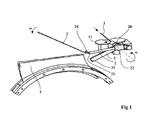
La figure 1 illustre un appareil de ce type utilisant ce principe. Un tel appareil utilise un fil 1 conditionné par exemple sous la forme d'une bobine d'alimentation, non représentée. L'appareil projette des tronçons de fils sur une surface de réception (non représentée) qui peut être constituée par la surface du pneumatique ou encore par tout autre surface telle qu'un anneau de renforcement sommet destiné à être transféré sur l'ébauche de pneumatique ou encore une surface plane destinée à former une nappe de renforcement sommet sous forme de produit semi fini.Figure 1 illustrates an apparatus of this type using this principle. Such an apparatus uses a
Le terme fil doit être compris dans un sens tout à fait général, englobant un mono filament, un multi filament, un câblé ou un retors ou un assemblage équivalent, et ceci, quelle que soit la matière constituant le fil ou le traitement qu'il pourrait subir, par exemple un traitement de surface pour favoriser sa liaison intime avec du caoutchouc, voire encore un traitement de gommage entourant ledit fil d'une couche de caoutchouc pour permettre son adhésion directe sur le support lors de sa projection.The term "wire" must be understood in a completely general sense, encompassing a mono-filament, a multi-filament, a cord or a plied or an equivalent assembly, and this, whatever the material constituting the wire or the treatment that it could undergo, for example a surface treatment to promote its intimate connection with rubber, or even a scrubbing treatment surrounding said wire with a rubber layer to allow its direct adhesion to the support during its projection.
Ledit dispositif comprend :
- des moyens d'appel 11 de
fil 1 à partir d'une source de fil, - un conduit rotatif 2 fixé sur un
arbre 20 constituant l'axe de rotation dudit conduit, de manière telle que l'extrémité radiale extérieure 21 dudit conduit soit orientée sensiblement radialement par rapport à l'axe de rotation, ledit conduit recevant lefil 1 par son extrémité centrale 22 opposée à ladite extrémité radiale extérieure 21 en provenance desdits moyens d'appel, ledit fil sortant par ladite extrémité radiale extérieure, lesdits moyens d'appel contrôlant la vitesse linéaire d'avance du fil à l'intérieur dudit conduit rotatif, - des moyens pour entraîner en rotation ledit conduit rotatif,
- des moyens pour sectionner le fil (31, 24) agissant sur le fil de façon à libérer un tronçon à chaque tour dudit conduit rotatif.
- wire call means 11 from a wire source,
- a
rotary duct 2 fixed on ashaft 20 constituting the axis of rotation of said duct, such that the radiallyouter end 21 of said duct is oriented substantially radially with respect to the axis of rotation, said duct receiving thewire 1 by itscentral end 22 opposite said outerradial end 21 from said means of call, said wire exiting through said outer radial end, said call means controlling the linear speed of advance of the wire to the inside said rotary duct, - means for rotating said rotary duct,
- means for severing the yarn (31, 24) acting on the yarn to release a section at each turn of said rotary duct.
Pour plus de détails sur le fonctionnement de cet appareil il est suggéré de consulter la publication
Ce dispositif peut comprendre en outre un guide fil 4 pour recevoir et guider des tronçons de fil, comme cela est décrit également dans la publication
L'objet de l'invention concerne le système de coupe utilisé dans ce type d'appareil.The object of the invention relates to the cutting system used in this type of apparatus.
Il a en effet été mis en évidence que le tronçon de fil se déforme pendant sa course libre sous l'action de l'énergie emmagasinée au moment de la coupe. Cette déformation est alors susceptible de modifier sensiblement la configuration du fil au moment où ce dernier « attérit » sur la surface de réception.It has indeed been shown that the wire section deforms during its free run under the action of energy stored at the time of cutting. This deformation is then likely to substantially change the configuration of the wire at the moment when the latter "lands" on the receiving surface.
L'invention a pour objet de corriger ce phénomène. A cet effet, un heurtoir est disposé sur le parcours de l'extrémité libre du tronçon de fil susceptible de se déformer de telle sorte que, lorsque le dispositif est en fonctionnement, ladite extrémité vienne frapper ledit heurtoir avant de rentrer en contact avec ladite surface de réception S.The object of the invention is to correct this phenomenon. For this purpose, a knocker is arranged on the path of the free end of the section of wire capable of deforming so that, when the device is in operation, said end comes to hit said knocker before coming into contact with said surface reception S.
La description qui suit a pour objet de mettre en évidence le phénomène physique dont il est question et d'un mode particulier de réalisation de l'invention en s'appuyant sur les figures 1 à 9 dans lesquelles :
- La figure 1 représente une vue schématique en perspective d'un dispositif de pose,
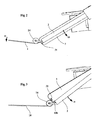
- Les figures 2 à 5 représentent des vues schématiques de la cinématique du fil et du tronçon de fil avant et après la coupe,
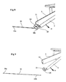
- la figure 6 représente une vue schématique de coté d'un dispositif de coupe équipé d'un heurtoir selon l'invention,
- la figure 7 représente le même dispositif vue selon une coupe frontale selon AA,
- les figures 8 et 9 représentent des vues schématiques de la cinématique de l'extrémité 10b du tronçon de
fil 10 lorsque le moyen de coupe est équipé d'un heurtoir selon l'invention.
- FIG. 1 represents a schematic perspective view of a laying device,
- Figures 2 to 5 show schematic views of the kinematics of the wire and the wire section before and after cutting,
- FIG. 6 represents a schematic side view of a cutting device equipped with a knocker according to the invention,
- FIG. 7 represents the same device seen in front section along AA,
- Figures 8 and 9 show schematic views of the kinematics of the
end 10b of thewire section 10 when the cutting means is equipped with a knocker according to the invention.
Pour la compréhension de la description qui suit, on désignera par le chiffre repère 1 le fil non sectionné et par le chiffre repère 10 le tronçon de fil, lorsque ce dernier est séparé du fil. De même, le tronçon de fil comprend deux extrémités, désignées respectivement par les repères 10 a et 10b, l'extrémité 10a correspondant à l'extrémité la plus éloignée de l'ensemble de coupe, et l'extrémité 10b correspondant à l'extrémité la plus proche de l'ensemble de coupe et par voie de conséquence de l'extrémité radiale extérieure 21 du conduit rotatif 2.For the understanding of the description which follows, the
Les moyens pour sectionner le fil 1 de manière à libérer un tronçon de fil 10 sont formés en règle générale d'un couteau 31 et d'un organe jouant le rôle d'une enclume 24. L'un de ces éléments est rendu mobile par rapport à l'autre. Le fil est maintenu par l'enclume 24, et sectionné par le couteau 31. Pour que le fil soit sectionné, il est indifférent que le couteau soit mobile par rapport à l'enclume ou que réciproquement, l'enclume soit mobile par rapport au couteau. Aussi, dans le repère du fil, et par convention, on désignera par l'enclume, la partie fixe du moyen de coupe, et par le couteau la partie mobile du moyen de coupe. L'enclume peut être constituée par exemple par un galet apte à servir également de guide au fil sortant du conduit rotatif 2.The means for severing the
Il a été mis en évidence que l'action du couteau 31 sur le fil avait pour effet de conférer une certaine quantité de mouvement à l'extrémité 10b du tronçon de fil placé du coté du moyen de coupe. Cette quantité de mouvement est orientée dans le sens du mouvement du couteau ou de la partie mobile du moyen de coupe.It has been demonstrated that the action of the
D'autre part, une fois libéré par la coupe, le tronçon de fil 10 effectue un déplacement libre dans l'espace avant de rencontrer la surface de pose. Il s'en suit que, au cours de ce déplacement libre, l'extrémité 10b va restituer la quantité de mouvement en générant un déplacement de ladite extrémité dans le sens opposé, ce qui a pour effet de déformer l'extrémité 10b et de modifier localement de manière sensible la forme généralement rectiligne du tronçon de fil 10.On the other hand, once released by the section, the section of
Les figures 2 à 5 permettent de comprendre et de visualiser de façon schématique le phénomène physique dont on cherche à corriger les effets.Figures 2 to 5 allow to understand and visualize schematically the physical phenomenon whose effects we seek to correct.
Le fil 1 est déroulé par les moyens d'appel de manière à délivrer la longueur de tronçon de fil voulu à chaque rotation du conduit rotatif 2. Le couteau 31 est placé en extrémité d'un bras fixe 3. L'enclume 24 est disposée à l'extrémité radiale du conduit 2 qui tourne autour de son axe à une vitesse de rotation égale à ω. L'enclume 24 est fixe dans le repère relatif du fil. Le fil 1 est sectionné au passage du bras 2 au droit du couteau 31. Le couteau a une vitesse relative égale à -ω par rapport à l'enclume 24 et au fil 1.The
La figure 2 représente les positions respectives du fil 1 de l'enclume 24 et du couteau 31, juste avant la coupe. La figure 3 montre la forme de l'extrémité 10b juste après le passage du couteau 31. On observe à cet instant que l'extrémité 10b du tronçon 10 pivote autour de l'enclume 24, et que ladite extrémité est entraînée par le couteau 31.Figure 2 shows the respective positions of the
La figure 4 montre le tronçon 10 qui a été projeté en direction de la surface de réception S (non représentée), alors que ledit tronçon est en train de se dégager de l'extrémité du conduit rotatif 2. L'extrémité 10b est alors encore en contact avec l'enclume 24 et pivote autour de ce point dans la direction opposée à la direction du mouvement du couteau par rapport au fil. Dans cette configuration, l'extrémité 10b s'incline dans la direction du mouvement du fil, ce qui est représenté à la figure 5, sur laquelle on observe que le tronçon de fil a une forme généralement rectiligne et que l'extrémité 10b est recourbée dans la direction de la surface de réception.FIG. 4 shows the
Il résulte de ce phénomène que, dans certaines gammes de vitesse de fonctionnement, lorsque le fil « atterrit » sur la surface de réception S , l'extrémité 10b n'est pas positionnée de manière suffisamment précise et reproductible, en regard des critères retenus pour conférer au pneumatique toutes les performances désirées.As a result of this phenomenon, in certain operating speed ranges, when the wire "lands" on the receiving surface S, the
L'invention a pour objet de combattre ce phénomène de déformation de l'extrémité du tronçon de fil, de manière à ce que le tronçon de fil ait une forme sensiblement rectiligne au moment de sa mise en contact avec la surface de réception.The invention aims to combat this deformation phenomenon of the end of the wire section, so that the wire section has a substantially rectilinear shape at the time of its contact with the receiving surface.
Pour atteindre le résultat recherché, il est proposé de placer un heurtoir 25 disposé sur le parcours de l'extrémité libre 10b du tronçon de fil 10 de telle sorte que ladite extrémité 10b vienne frapper ledit heurtoir avant de rentrer en contact avec la surface de réception.To achieve the desired result, it is proposed to place a
Le choc entre le heurtoir et l'extrémité libre 10b du tronçon 10 a pour effet de conférer à ladite extrémité une quantité de mouvement sensiblement équivalente et de sens opposé à la quantité de mouvement acquise par le fil après sa rotation autour de l'enclume 24, et conférée par le mouvement du couteau. La restitution de cette quantité de mouvement permet à l'extrémité libre 10b de se réaligner avec le reste du tronçon de fil 10.The impact between the knocker and the
L'invention concerne également le procédé mettant en oeuvre le dispositif;The invention also relates to the method implementing the device;
Ce procédé de réalisation d'un renforcement pour pneumatique, ledit renforcement comportant des fils adjacents et sensiblement parallèles, est un procédé du type dans lequel chaque tronçon de fil 10 est projeté individuellement à son emplacement sur une surface de réception S. Les tronçons de fil 10 sont projetés par des moyens en rotation 2, la surface de réception et le fil ayant des propriétés d'auto-adhésion.This method of producing a reinforcement for a tire, said reinforcement comprising adjacent and substantially parallel threads, is a method of the type in which each
Lesdits moyens en rotation comprennent
- des moyens d'appel 11 de fil 1 à partir d'une source de fil,
- un conduit rotatif 2 fixé sur un arbre 20 constituant l'axe de rotation dudit conduit, de manière telle que l'extrémité radiale extérieure 21 dudit conduit soit orientée sensiblement radialement par rapport à l'axe de rotation, ledit conduit recevant le fil 1 par son
extrémité centrale 22 opposée à ladite extrémité radiale extérieure 21 en provenance desdits moyens d'appel, ledit fil sortant par ladite extrémité radiale extérieure, lesdits moyens d'appel contrôlant la vitesse de progression du fil à l'intérieur dudit conduit rotatif, - des moyens pour entraîner en rotation ledit conduit rotatif,
- des moyens pour sectionner le fil comprenant une enclume 24 fixe par rapport au fil, et un couteau mobile 31 agissant sur le fil en collaboration avec ladite enclume 24 de façon à libérer, à chaque tour dudit conduit rotatif,
un tronçon 10dont l'extrémité 10b est l'extrémité du tronçon située du coté du moyen de coupe.
- wire call means 11 from a wire source,
- a
rotary duct 2 fixed on ashaft 20 constituting the axis of rotation of said duct, such that the outerradial end 21 of said duct is oriented substantially radially with respect to the axis of rotation, said duct receiving theyarn 1 through itscentral end 22 opposite to said outerradial end 21 from said call means, said wire exiting through said outer radial end, said calling means controlling the speed of progression of the wire inside said rotary duct, - means for rotating said rotary duct,
- means for severing the wire comprising an
anvil 24 fixed with respect to the wire, and amovable knife 31 acting on the wire in conjunction with saidanvil 24 so as to release, at each turn of said rotary duct, asection 10 whoseend 10b is the end of the section located on the side of the cutting means.
Ce procédé se caractérise en ce que l'extrémité 10b du tronçon de fil vient frapper un heurtoir 25 avant de prendre contact avec la surface de réception S.This method is characterized in that the
La figure 6 représente le conduit rotatif 2 dans la position qui précède la coupe du fil 1 par le couteau 31.FIG. 6 represents the
Le fil 1 sort du conduit rotatif 2 par l'extrémité radiale 21 dudit conduit. Ledit conduit rotatif est entraîné en rotation par des moyens de mise en rotation (non représentés). Les moyens d'appels 11 (non représentés) délivrent une longueur voulue de fil qui, sous l'effet de la force centrifuge, se déploie dans l'espace à la manière de la lanière d'un fouet dans la direction de la flèche D.The
Une enclume 24 est fixée à l'extrémité du conduit rotatif par l'intermédiaire d'un support 23. L'enclume peut servir également de moyen de guidage du fil 1 en sortie du conduit rotatif et peut tout aussi bien être monté sur un axe rotatif.An
Un heurtoir 25 est disposé sous l'enclume 24. Le heurtoir est rendu solidaire de l'extrémité du conduit par une attache reliée au support 23 de l'enclume 24.A
On s'arrange pour que ledit heurtoir soit disposé sur le parcours de l'extrémité libre 10b du tronçon de fil 10.It is arranged for said knocker to be arranged on the path of the
En pratique, il est possible de déterminer avec une bonne précision la trajectoire du tronçon de fil en utilisant un moyen d'éclairage stroboscopique couplé à un moyen d'enregistrement photographique dont le déclanchement est activé par le moyen d'éclairage. On peut alors suivre le trajet du tronçon de fil et déterminer la position du heurtoir.In practice, it is possible to determine with good accuracy the trajectory of the wire section by using a stroboscopic illumination means coupled to a photographic recording means whose triggering is activated by the lighting means. We can then follow the path of the wire section and determine the position of the knocker.
Le mode préférentiel de réalisation consiste à disposer le heurtoir sur le conduit rotatif. Ce mode de réalisation permet en pratique de corriger avec une grande précision la forme du fil dés la sortie du conduit rotatif, tout en réduisant l'encombrement du dispositif.The preferred embodiment consists in arranging the knocker on the rotary duct. This embodiment makes it possible in practice to correct with great precision the shape of the wire from the output of the rotary conduit, while reducing the size of the device.
La forme du heurtoir est déterminée par la longueur spécifique de mise en contact avec l'extrémité 10b du tronçon 10, laquelle est dépendante de la quantité d'énergie qu'il est nécessaire de conférer à ladite extrémité pour la redresser. En pratique cette longueur est comprise entre environ 5 mm et environ 15 mm.The shape of the knocker is determined by the specific length of contact with the
Il a par ailleurs été constaté que le fait que le conduit soit en rotation par rapport au tronçon de fil 10 au moment du choc était d'un effet secondaire pour l'obtention du résultat recherché.It has also been found that the fact that the conduit is rotated relative to the
Le bras 3 est fixe par rapport au conduit rotatif 2 et comporte à son extrémité un couteau 31.The
Sous l'effet du mouvement rotatif relatif du conduit par rapport au bras, le couteau 31 tranche le fil 1 qui est retenu par l'enclume 24.Under the effect of the relative rotational movement of the duct relative to the arm, the
La présente description a pour objet une forme préférentielle de réalisation de l'invention permettant de rectifier la forme de l'extrémité 10b du tronçon de fil avant qu'il « n'atterrisse » sur la surface de réception. Toutefois, l'homme du métier pourra adapter à sa convenance la disposition des différents organes pour obtenir l'effet recherché.The present disclosure relates to a preferred embodiment of the invention for rectifying the shape of the
Claims (6)
Applications Claiming Priority (1)
| Application Number | Priority Date | Filing Date | Title |
|---|---|---|---|
| FR0609647A FR2908072A1 (en) | 2006-11-02 | 2006-11-02 | DEVICE AND METHOD FOR GUIDING A WIRE |
Publications (2)
| Publication Number | Publication Date |
|---|---|
| EP1918088A1 true EP1918088A1 (en) | 2008-05-07 |
| EP1918088B1 EP1918088B1 (en) | 2010-04-14 |
Family
ID=37980574
Family Applications (1)
| Application Number | Title | Priority Date | Filing Date |
|---|---|---|---|
| EP20070118441 Not-in-force EP1918088B1 (en) | 2006-11-02 | 2007-10-15 | Device and method of guiding a cord |
Country Status (8)
| Country | Link |
|---|---|
| US (1) | US7976660B2 (en) |
| EP (1) | EP1918088B1 (en) |
| JP (1) | JP5226274B2 (en) |
| CN (1) | CN101172397B (en) |
| AT (1) | ATE464175T1 (en) |
| BR (1) | BRPI0704391A (en) |
| DE (1) | DE602007005895D1 (en) |
| FR (1) | FR2908072A1 (en) |
Families Citing this family (1)
| Publication number | Priority date | Publication date | Assignee | Title |
|---|---|---|---|---|
| JP5773511B2 (en) * | 2013-04-25 | 2015-09-02 | ホリゾン・インターナショナル株式会社 | Punching machine |
Citations (5)
| Publication number | Priority date | Publication date | Assignee | Title |
|---|---|---|---|---|
| US3570353A (en) * | 1968-05-13 | 1971-03-16 | Heberlein & Co Ag | Electromagnetic cutting device with change-over switch |
| DE2233999A1 (en) * | 1972-07-11 | 1974-01-31 | Spinnerei Karl Marx Veb | Thread cutter and clamp - for spinning or winding machine |
| US3894906A (en) * | 1973-06-01 | 1975-07-15 | Nat Standard Co | Apparatus for making tire breakers |
| EP0845348A1 (en) * | 1996-11-27 | 1998-06-03 | Sedepro | Adjustable guidewire assembly for guiding cords being projected on a surface |
| EP1147864A2 (en) * | 2000-04-18 | 2001-10-24 | Sedepro | High speed cutting device for cutting reinforcing elements for tyres |
Family Cites Families (8)
| Publication number | Priority date | Publication date | Assignee | Title |
|---|---|---|---|---|
| US3680616A (en) * | 1970-04-06 | 1972-08-01 | Pillsbury Co | Method and apparatus for severing food products |
| JPS62222824A (en) | 1986-03-25 | 1987-09-30 | Kinugawa Rubber Ind Co Ltd | Apparatus for preparing weather strip containing core material |
| FR2694519A1 (en) * | 1992-08-07 | 1994-02-11 | Sedepro | Method of manufacturing a tire and machine for manufacturing a crown reinforcement for a tire. |
| FR2756212A1 (en) * | 1996-11-27 | 1998-05-29 | Sedepro | REMOVABLE WIRE GUIDE, RECEIVING WIRES PROJECTED ON A SURFACE |
| US5971050A (en) * | 1996-11-27 | 1999-10-26 | Sedepro | Removable thread guide which receives threads projected onto a surface |
| JP3894621B2 (en) * | 1997-06-27 | 2007-03-22 | 株式会社ブリヂストン | Cord member terminal processing device |
| WO2002020898A2 (en) | 2000-08-30 | 2002-03-14 | Owens Corning | Die for making composite cable |
| WO2005075180A1 (en) * | 2004-01-27 | 2005-08-18 | Societe De Technologie Michelin | Device for producing a tyre reinforcement |
-
2006
- 2006-11-02 FR FR0609647A patent/FR2908072A1/en active Pending
-
2007
- 2007-10-15 AT AT07118441T patent/ATE464175T1/en not_active IP Right Cessation
- 2007-10-15 EP EP20070118441 patent/EP1918088B1/en not_active Not-in-force
- 2007-10-15 DE DE200760005895 patent/DE602007005895D1/en active Active
- 2007-10-26 CN CN2007101675451A patent/CN101172397B/en not_active Expired - Fee Related
- 2007-10-31 JP JP2007283420A patent/JP5226274B2/en not_active Expired - Fee Related
- 2007-10-31 BR BRPI0704391-0A patent/BRPI0704391A/en active Search and Examination
- 2007-11-02 US US11/982,606 patent/US7976660B2/en not_active Expired - Fee Related
Patent Citations (5)
| Publication number | Priority date | Publication date | Assignee | Title |
|---|---|---|---|---|
| US3570353A (en) * | 1968-05-13 | 1971-03-16 | Heberlein & Co Ag | Electromagnetic cutting device with change-over switch |
| DE2233999A1 (en) * | 1972-07-11 | 1974-01-31 | Spinnerei Karl Marx Veb | Thread cutter and clamp - for spinning or winding machine |
| US3894906A (en) * | 1973-06-01 | 1975-07-15 | Nat Standard Co | Apparatus for making tire breakers |
| EP0845348A1 (en) * | 1996-11-27 | 1998-06-03 | Sedepro | Adjustable guidewire assembly for guiding cords being projected on a surface |
| EP1147864A2 (en) * | 2000-04-18 | 2001-10-24 | Sedepro | High speed cutting device for cutting reinforcing elements for tyres |
Also Published As
| Publication number | Publication date |
|---|---|
| ATE464175T1 (en) | 2010-04-15 |
| DE602007005895D1 (en) | 2010-05-27 |
| JP5226274B2 (en) | 2013-07-03 |
| JP2008114596A (en) | 2008-05-22 |
| CN101172397B (en) | 2012-10-03 |
| US7976660B2 (en) | 2011-07-12 |
| EP1918088B1 (en) | 2010-04-14 |
| BRPI0704391A (en) | 2008-10-21 |
| US20080105359A1 (en) | 2008-05-08 |
| CN101172397A (en) | 2008-05-07 |
| FR2908072A1 (en) | 2008-05-09 |
Similar Documents
| Publication | Publication Date | Title |
|---|---|---|
| CA2071445C (en) | Tire fabrication process, and machines for implementing said process | |
| EP0580055B1 (en) | Process and apparatus for arranging on a core a single reinforcing wire in the manufacturing of tire carcasses | |
| EP1122057B1 (en) | Swing arm apparatus for manufacturing a tyre reinforcing structure using a single thread | |
| EP0519295B1 (en) | Method for the production of a tyre and apparatus for the implementation of the method | |
| FR2599297A1 (en) | PROCESS AND MACHINE FOR MANUFACTURING A REINFORCEMENT FOR TIRES | |
| EP1231050B1 (en) | Swing arm apparatus for manufacturing a tyre reinforcing structure using a single thread | |
| EP2536875B1 (en) | Needle for insertion of a thread in a tyre | |
| EP1231049B1 (en) | Swing arm apparatus for manufacturing a tyre reinforcing structure using a single thread | |
| EP1918088B1 (en) | Device and method of guiding a cord | |
| EP1711335B1 (en) | Method and device for producing a tyre reinforcement | |
| FR2756213A1 (en) | WIRE GUIDE WITH ADJUSTABLE BRAKE, RECEIVING WIRES PROJECTED ONTO A SURFACE | |
| EP1426170B1 (en) | Apparatus having multiple application arms for the manufacture of a reinforcing element for tyres | |
| EP1426169B1 (en) | Apparatus for the manufacture of a reinforcing element for large-dimension tyres | |
| EP1733867B1 (en) | Device for depositing reinforcement cord | |
| EP2203302B1 (en) | Rotary laying arm comprising an on-board filament feed means | |
| EP1938960B1 (en) | Method for determining the operating parameters of a device for laying a wire by projection | |
| FR2937576A1 (en) | Wooden revolution part i.e. fishing float, fabricating method, involves continuously adjusting distance between axes of cutting tools and axis of bar according to translation position of bar with respect to chassis |
Legal Events
| Date | Code | Title | Description |
|---|---|---|---|
| PUAI | Public reference made under article 153(3) epc to a published international application that has entered the european phase |
Free format text: ORIGINAL CODE: 0009012 |
|
| AK | Designated contracting states |
Kind code of ref document: A1 Designated state(s): AT BE BG CH CY CZ DE DK EE ES FI FR GB GR HU IE IS IT LI LT LU LV MC MT NL PL PT RO SE SI SK TR |
|
| AX | Request for extension of the european patent |
Extension state: AL BA HR MK RS |
|
| 17P | Request for examination filed |
Effective date: 20081107 |
|
| 17Q | First examination report despatched |
Effective date: 20081208 |
|
| AKX | Designation fees paid |
Designated state(s): AT BE BG CH CY CZ DE DK EE ES FI FR GB GR HU IE IS IT LI LT LU LV MC MT NL PL PT RO SE SI SK TR |
|
| GRAP | Despatch of communication of intention to grant a patent |
Free format text: ORIGINAL CODE: EPIDOSNIGR1 |
|
| GRAS | Grant fee paid |
Free format text: ORIGINAL CODE: EPIDOSNIGR3 |
|
| GRAA | (expected) grant |
Free format text: ORIGINAL CODE: 0009210 |
|
| AK | Designated contracting states |
Kind code of ref document: B1 Designated state(s): AT BE BG CH CY CZ DE DK EE ES FI FR GB GR HU IE IS IT LI LT LU LV MC MT NL PL PT RO SE SI SK TR |
|
| REG | Reference to a national code |
Ref country code: GB Ref legal event code: FG4D Free format text: NOT ENGLISH |
|
| REG | Reference to a national code |
Ref country code: CH Ref legal event code: EP |
|
| REG | Reference to a national code |
Ref country code: IE Ref legal event code: FG4D Free format text: LANGUAGE OF EP DOCUMENT: FRENCH |
|
| REF | Corresponds to: |
Ref document number: 602007005895 Country of ref document: DE Date of ref document: 20100527 Kind code of ref document: P |
|
| REG | Reference to a national code |
Ref country code: NL Ref legal event code: VDEP Effective date: 20100414 |
|
| LTIE | Lt: invalidation of european patent or patent extension |
Effective date: 20100414 |
|
| PG25 | Lapsed in a contracting state [announced via postgrant information from national office to epo] |
Ref country code: NL Free format text: LAPSE BECAUSE OF FAILURE TO SUBMIT A TRANSLATION OF THE DESCRIPTION OR TO PAY THE FEE WITHIN THE PRESCRIBED TIME-LIMIT Effective date: 20100414 Ref country code: SE Free format text: LAPSE BECAUSE OF FAILURE TO SUBMIT A TRANSLATION OF THE DESCRIPTION OR TO PAY THE FEE WITHIN THE PRESCRIBED TIME-LIMIT Effective date: 20100414 Ref country code: ES Free format text: LAPSE BECAUSE OF FAILURE TO SUBMIT A TRANSLATION OF THE DESCRIPTION OR TO PAY THE FEE WITHIN THE PRESCRIBED TIME-LIMIT Effective date: 20100725 Ref country code: LT Free format text: LAPSE BECAUSE OF FAILURE TO SUBMIT A TRANSLATION OF THE DESCRIPTION OR TO PAY THE FEE WITHIN THE PRESCRIBED TIME-LIMIT Effective date: 20100414 |
|
| REG | Reference to a national code |
Ref country code: IE Ref legal event code: FD4D |
|
| PG25 | Lapsed in a contracting state [announced via postgrant information from national office to epo] |
Ref country code: AT Free format text: LAPSE BECAUSE OF FAILURE TO SUBMIT A TRANSLATION OF THE DESCRIPTION OR TO PAY THE FEE WITHIN THE PRESCRIBED TIME-LIMIT Effective date: 20100414 Ref country code: FI Free format text: LAPSE BECAUSE OF FAILURE TO SUBMIT A TRANSLATION OF THE DESCRIPTION OR TO PAY THE FEE WITHIN THE PRESCRIBED TIME-LIMIT Effective date: 20100414 Ref country code: IS Free format text: LAPSE BECAUSE OF FAILURE TO SUBMIT A TRANSLATION OF THE DESCRIPTION OR TO PAY THE FEE WITHIN THE PRESCRIBED TIME-LIMIT Effective date: 20100814 Ref country code: LV Free format text: LAPSE BECAUSE OF FAILURE TO SUBMIT A TRANSLATION OF THE DESCRIPTION OR TO PAY THE FEE WITHIN THE PRESCRIBED TIME-LIMIT Effective date: 20100414 Ref country code: SI Free format text: LAPSE BECAUSE OF FAILURE TO SUBMIT A TRANSLATION OF THE DESCRIPTION OR TO PAY THE FEE WITHIN THE PRESCRIBED TIME-LIMIT Effective date: 20100414 |
|
| PG25 | Lapsed in a contracting state [announced via postgrant information from national office to epo] |
Ref country code: PL Free format text: LAPSE BECAUSE OF FAILURE TO SUBMIT A TRANSLATION OF THE DESCRIPTION OR TO PAY THE FEE WITHIN THE PRESCRIBED TIME-LIMIT Effective date: 20100414 Ref country code: CY Free format text: LAPSE BECAUSE OF FAILURE TO SUBMIT A TRANSLATION OF THE DESCRIPTION OR TO PAY THE FEE WITHIN THE PRESCRIBED TIME-LIMIT Effective date: 20100526 |
|
| PG25 | Lapsed in a contracting state [announced via postgrant information from national office to epo] |
Ref country code: PT Free format text: LAPSE BECAUSE OF FAILURE TO SUBMIT A TRANSLATION OF THE DESCRIPTION OR TO PAY THE FEE WITHIN THE PRESCRIBED TIME-LIMIT Effective date: 20100816 Ref country code: DK Free format text: LAPSE BECAUSE OF FAILURE TO SUBMIT A TRANSLATION OF THE DESCRIPTION OR TO PAY THE FEE WITHIN THE PRESCRIBED TIME-LIMIT Effective date: 20100414 Ref country code: EE Free format text: LAPSE BECAUSE OF FAILURE TO SUBMIT A TRANSLATION OF THE DESCRIPTION OR TO PAY THE FEE WITHIN THE PRESCRIBED TIME-LIMIT Effective date: 20100414 Ref country code: IE Free format text: LAPSE BECAUSE OF FAILURE TO SUBMIT A TRANSLATION OF THE DESCRIPTION OR TO PAY THE FEE WITHIN THE PRESCRIBED TIME-LIMIT Effective date: 20100414 |
|
| PLBE | No opposition filed within time limit |
Free format text: ORIGINAL CODE: 0009261 |
|
| STAA | Information on the status of an ep patent application or granted ep patent |
Free format text: STATUS: NO OPPOSITION FILED WITHIN TIME LIMIT |
|
| PG25 | Lapsed in a contracting state [announced via postgrant information from national office to epo] |
Ref country code: CZ Free format text: LAPSE BECAUSE OF FAILURE TO SUBMIT A TRANSLATION OF THE DESCRIPTION OR TO PAY THE FEE WITHIN THE PRESCRIBED TIME-LIMIT Effective date: 20100414 Ref country code: SK Free format text: LAPSE BECAUSE OF FAILURE TO SUBMIT A TRANSLATION OF THE DESCRIPTION OR TO PAY THE FEE WITHIN THE PRESCRIBED TIME-LIMIT Effective date: 20100414 Ref country code: RO Free format text: LAPSE BECAUSE OF FAILURE TO SUBMIT A TRANSLATION OF THE DESCRIPTION OR TO PAY THE FEE WITHIN THE PRESCRIBED TIME-LIMIT Effective date: 20100414 |
|
| 26N | No opposition filed |
Effective date: 20110117 |
|
| PG25 | Lapsed in a contracting state [announced via postgrant information from national office to epo] |
Ref country code: GR Free format text: LAPSE BECAUSE OF FAILURE TO SUBMIT A TRANSLATION OF THE DESCRIPTION OR TO PAY THE FEE WITHIN THE PRESCRIBED TIME-LIMIT Effective date: 20100715 |
|
| BERE | Be: lapsed |
Owner name: MICHELIN RECHERCHE ET TECHNIQUE S.A. Effective date: 20101031 Owner name: SOC. DE TECHNOLOGIE MICHELIN Effective date: 20101031 |
|
| PG25 | Lapsed in a contracting state [announced via postgrant information from national office to epo] |
Ref country code: MC Free format text: LAPSE BECAUSE OF NON-PAYMENT OF DUE FEES Effective date: 20101031 |
|
| PG25 | Lapsed in a contracting state [announced via postgrant information from national office to epo] |
Ref country code: BE Free format text: LAPSE BECAUSE OF NON-PAYMENT OF DUE FEES Effective date: 20101031 |
|
| PG25 | Lapsed in a contracting state [announced via postgrant information from national office to epo] |
Ref country code: IT Free format text: LAPSE BECAUSE OF NON-PAYMENT OF DUE FEES Effective date: 20101015 Ref country code: MT Free format text: LAPSE BECAUSE OF FAILURE TO SUBMIT A TRANSLATION OF THE DESCRIPTION OR TO PAY THE FEE WITHIN THE PRESCRIBED TIME-LIMIT Effective date: 20100414 |
|
| REG | Reference to a national code |
Ref country code: CH Ref legal event code: PL |
|
| GBPC | Gb: european patent ceased through non-payment of renewal fee |
Effective date: 20111015 |
|
| PG25 | Lapsed in a contracting state [announced via postgrant information from national office to epo] |
Ref country code: LI Free format text: LAPSE BECAUSE OF NON-PAYMENT OF DUE FEES Effective date: 20111031 Ref country code: CH Free format text: LAPSE BECAUSE OF NON-PAYMENT OF DUE FEES Effective date: 20111031 |
|
| PG25 | Lapsed in a contracting state [announced via postgrant information from national office to epo] |
Ref country code: GB Free format text: LAPSE BECAUSE OF NON-PAYMENT OF DUE FEES Effective date: 20111015 |
|
| PG25 | Lapsed in a contracting state [announced via postgrant information from national office to epo] |
Ref country code: HU Free format text: LAPSE BECAUSE OF FAILURE TO SUBMIT A TRANSLATION OF THE DESCRIPTION OR TO PAY THE FEE WITHIN THE PRESCRIBED TIME-LIMIT Effective date: 20101015 Ref country code: LU Free format text: LAPSE BECAUSE OF NON-PAYMENT OF DUE FEES Effective date: 20101015 Ref country code: BG Free format text: LAPSE BECAUSE OF FAILURE TO SUBMIT A TRANSLATION OF THE DESCRIPTION OR TO PAY THE FEE WITHIN THE PRESCRIBED TIME-LIMIT Effective date: 20100414 |
|
| PG25 | Lapsed in a contracting state [announced via postgrant information from national office to epo] |
Ref country code: TR Free format text: LAPSE BECAUSE OF FAILURE TO SUBMIT A TRANSLATION OF THE DESCRIPTION OR TO PAY THE FEE WITHIN THE PRESCRIBED TIME-LIMIT Effective date: 20100414 |
|
| PG25 | Lapsed in a contracting state [announced via postgrant information from national office to epo] |
Ref country code: BG Free format text: LAPSE BECAUSE OF FAILURE TO SUBMIT A TRANSLATION OF THE DESCRIPTION OR TO PAY THE FEE WITHIN THE PRESCRIBED TIME-LIMIT Effective date: 20100714 |
|
| REG | Reference to a national code |
Ref country code: FR Ref legal event code: PLFP Year of fee payment: 9 |
|
| REG | Reference to a national code |
Ref country code: FR Ref legal event code: PLFP Year of fee payment: 10 |
|
| REG | Reference to a national code |
Ref country code: FR Ref legal event code: PLFP Year of fee payment: 11 |
|
| REG | Reference to a national code |
Ref country code: FR Ref legal event code: PLFP Year of fee payment: 12 |
|
| PGFP | Annual fee paid to national office [announced via postgrant information from national office to epo] |
Ref country code: DE Payment date: 20181019 Year of fee payment: 12 |
|
| PGFP | Annual fee paid to national office [announced via postgrant information from national office to epo] |
Ref country code: IT Payment date: 20181024 Year of fee payment: 12 Ref country code: FR Payment date: 20181022 Year of fee payment: 12 |
|
| REG | Reference to a national code |
Ref country code: DE Ref legal event code: R119 Ref document number: 602007005895 Country of ref document: DE |
|
| PG25 | Lapsed in a contracting state [announced via postgrant information from national office to epo] |
Ref country code: DE Free format text: LAPSE BECAUSE OF NON-PAYMENT OF DUE FEES Effective date: 20200501 |
|
| PG25 | Lapsed in a contracting state [announced via postgrant information from national office to epo] |
Ref country code: FR Free format text: LAPSE BECAUSE OF NON-PAYMENT OF DUE FEES Effective date: 20191031 Ref country code: IT Free format text: LAPSE BECAUSE OF NON-PAYMENT OF DUE FEES Effective date: 20191015 |