EP1147864A2 - High speed cutting device for cutting reinforcing elements for tyres - Google Patents
High speed cutting device for cutting reinforcing elements for tyres Download PDFInfo
- Publication number
- EP1147864A2 EP1147864A2 EP01108701A EP01108701A EP1147864A2 EP 1147864 A2 EP1147864 A2 EP 1147864A2 EP 01108701 A EP01108701 A EP 01108701A EP 01108701 A EP01108701 A EP 01108701A EP 1147864 A2 EP1147864 A2 EP 1147864A2
- Authority
- EP
- European Patent Office
- Prior art keywords
- reinforcement
- support
- point
- wire
- cutting
- Prior art date
- Legal status (The legal status is an assumption and is not a legal conclusion. Google has not performed a legal analysis and makes no representation as to the accuracy of the status listed.)
- Granted
Links
Images

Classifications
-
- B—PERFORMING OPERATIONS; TRANSPORTING
- B26—HAND CUTTING TOOLS; CUTTING; SEVERING
- B26D—CUTTING; DETAILS COMMON TO MACHINES FOR PERFORATING, PUNCHING, CUTTING-OUT, STAMPING-OUT OR SEVERING
- B26D1/00—Cutting through work characterised by the nature or movement of the cutting member or particular materials not otherwise provided for; Apparatus or machines therefor; Cutting members therefor
- B26D1/01—Cutting through work characterised by the nature or movement of the cutting member or particular materials not otherwise provided for; Apparatus or machines therefor; Cutting members therefor involving a cutting member which does not travel with the work
- B26D1/12—Cutting through work characterised by the nature or movement of the cutting member or particular materials not otherwise provided for; Apparatus or machines therefor; Cutting members therefor involving a cutting member which does not travel with the work having a cutting member moving about an axis
- B26D1/25—Cutting through work characterised by the nature or movement of the cutting member or particular materials not otherwise provided for; Apparatus or machines therefor; Cutting members therefor involving a cutting member which does not travel with the work having a cutting member moving about an axis with a non-circular cutting member
- B26D1/26—Cutting through work characterised by the nature or movement of the cutting member or particular materials not otherwise provided for; Apparatus or machines therefor; Cutting members therefor involving a cutting member which does not travel with the work having a cutting member moving about an axis with a non-circular cutting member moving about an axis substantially perpendicular to the line of cut
- B26D1/28—Cutting through work characterised by the nature or movement of the cutting member or particular materials not otherwise provided for; Apparatus or machines therefor; Cutting members therefor involving a cutting member which does not travel with the work having a cutting member moving about an axis with a non-circular cutting member moving about an axis substantially perpendicular to the line of cut and rotating continuously in one direction during cutting
-
- B—PERFORMING OPERATIONS; TRANSPORTING
- B21—MECHANICAL METAL-WORKING WITHOUT ESSENTIALLY REMOVING MATERIAL; PUNCHING METAL
- B21F—WORKING OR PROCESSING OF METAL WIRE
- B21F11/00—Cutting wire
-
- B—PERFORMING OPERATIONS; TRANSPORTING
- B29—WORKING OF PLASTICS; WORKING OF SUBSTANCES IN A PLASTIC STATE IN GENERAL
- B29D—PRODUCING PARTICULAR ARTICLES FROM PLASTICS OR FROM SUBSTANCES IN A PLASTIC STATE
- B29D30/00—Producing pneumatic or solid tyres or parts thereof
- B29D30/06—Pneumatic tyres or parts thereof (e.g. produced by casting, moulding, compression moulding, injection moulding, centrifugal casting)
- B29D30/38—Textile inserts, e.g. cord or canvas layers, for tyres; Treatment of inserts prior to building the tyre
- B29D30/46—Cutting textile inserts to required shape
-
- B—PERFORMING OPERATIONS; TRANSPORTING
- B29—WORKING OF PLASTICS; WORKING OF SUBSTANCES IN A PLASTIC STATE IN GENERAL
- B29D—PRODUCING PARTICULAR ARTICLES FROM PLASTICS OR FROM SUBSTANCES IN A PLASTIC STATE
- B29D30/00—Producing pneumatic or solid tyres or parts thereof
- B29D30/06—Pneumatic tyres or parts thereof (e.g. produced by casting, moulding, compression moulding, injection moulding, centrifugal casting)
- B29D30/08—Building tyres
- B29D30/10—Building tyres on round cores, i.e. the shape of the core is approximately identical with the shape of the completed tyre
- B29D30/16—Applying the layers; Guiding or stretching the layers during application
- B29D2030/1664—Details, accessories or auxiliary operations not provided for in the other subgroups of B29D30/00
- B29D2030/1685—Details, accessories or auxiliary operations not provided for in the other subgroups of B29D30/00 the layers being applied being already cut to the appropriate length, before the application step
-
- B—PERFORMING OPERATIONS; TRANSPORTING
- B29—WORKING OF PLASTICS; WORKING OF SUBSTANCES IN A PLASTIC STATE IN GENERAL
- B29D—PRODUCING PARTICULAR ARTICLES FROM PLASTICS OR FROM SUBSTANCES IN A PLASTIC STATE
- B29D30/00—Producing pneumatic or solid tyres or parts thereof
- B29D30/06—Pneumatic tyres or parts thereof (e.g. produced by casting, moulding, compression moulding, injection moulding, centrifugal casting)
- B29D30/08—Building tyres
- B29D30/20—Building tyres by the flat-tyre method, i.e. building on cylindrical drums
- B29D30/30—Applying the layers; Guiding or stretching the layers during application
- B29D2030/3064—Details, accessories and auxiliary operations not otherwise provided for
- B29D2030/3085—Details, accessories and auxiliary operations not otherwise provided for the layers being applied being already cut to the appropriate length, before the application step
-
- Y—GENERAL TAGGING OF NEW TECHNOLOGICAL DEVELOPMENTS; GENERAL TAGGING OF CROSS-SECTIONAL TECHNOLOGIES SPANNING OVER SEVERAL SECTIONS OF THE IPC; TECHNICAL SUBJECTS COVERED BY FORMER USPC CROSS-REFERENCE ART COLLECTIONS [XRACs] AND DIGESTS
- Y10—TECHNICAL SUBJECTS COVERED BY FORMER USPC
- Y10T—TECHNICAL SUBJECTS COVERED BY FORMER US CLASSIFICATION
- Y10T156/00—Adhesive bonding and miscellaneous chemical manufacture
- Y10T156/12—Surface bonding means and/or assembly means with cutting, punching, piercing, severing or tearing
- Y10T156/1317—Means feeding plural workpieces to be joined
Definitions
- the present invention relates to the manufacture of tires. More specifically, it relates to the manufacture of reinforcement, in particular for the top of the pneumatic.
- reinforcement In the present application, An important architectural parameter is the angle that form these reinforcements compared to a standard reference well known to men of the profession, namely the median plane perpendicular to the axis of rotation of the tire.
- the the present patent application relates in particular to zero-degree reinforcements, which that is the precise location of these reinforcements in the tire. Reinforcements can be made by depositing a single wire individually or by depositing a few wires simultaneously, by group of parallel wires, for example a dozen parallel wires.
- wire is used to refer to a single strand, such as a monofilament, or an assembly of unitary strands like a cable, and the term “reinforcement” also refers to without distinction a single wire, or a group of parallel wires.
- the wires can be bare or pre coated with rubber or any other material capable of making the wires sticky.
- the invention aims to provide very fast cutting means, that these cuts are frequent as in the case described above or that the cutting occurs only at the end of the operation concerning a tire, as in the case of reinforcements at zero degrees in continuous wire.
- the invention makes it possible to envisage in good performance conditions industrial laying of wire sections for any reinforcement application.
- Cutting on demand can be done by a suitable actuator.
- the construction of the command is such that the knife is active at the cutting point every n passages, n greater than or equal to two.
- the invention proposes to rotate a knife at very high speed and, by kinematics ensure that the knife is not active every time you pass the reinforcement.
- the invention exploits the arrangement known per se of satellite pinions existing in certain reducers. This allows to describe with a knife a trajectory included in a plane.
- the invention allows direct manufacture on a support, from coils in which the reinforcement is removed continuously.
- the support in question can be a form of revolution on which we build a crown block, or a drum which supports the raw tire during manufacture, or any other suitable support, the invention not in itself dealing with this aspect. So that the reinforcement placed remains in place on the support, it is advantageous that the support is coated with a layer of raw rubber to which the reinforcement can stick or adhere, or in which the reinforcement can penetrate at least slightly as and that it is brought on the support.
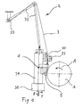
- a support 1 on which a reinforcement is made This support could be constituted by any type of shape defining the surface on which we are going to have the sections of wire constituting the reinforcement, such as for example a reinforced membrane inflatable, or a shape adjustable in diameter of the kind used in top block construction imposing a purely cylindrical profile, or a curved shape transversely.
- the support 1 is already coated with all the constituents that it must receive before the addition of zero degree reinforcement.
- the support 1 is rotated in the direction indicated by arrow A.
- the wire 3 is unwound from a coil (not shown). Wire 3 is engaged on different pulleys of a compass system 32 allowing it, from a fixed point in space (pulley 33), to join a laying head 34 movable in space.
- a robot 35 with three axes (Y, Z, ⁇ ) ensures correct presentation of wire 3 at any point on the surface of the support 1, even when the support is of non-cylindrical shape.
- the wire 3 On the laying head, the wire 3 is motorized by two rollers 20, 21 between which it is pinched. The roller 20 is driven by a motor (not shown) for advancing the wire 3.
- the feed motor can include an encoder or a resolver. It is thus possible to impose on the wire 3 a very precise linear advance while knowing in continuous precise measurement of the quantity of wire 3 delivered to the machine components arranged downstream.
- the wire 3 is introduced into a cutting device 4, installed on the laying head 34.
- the cutting device is, in this example, suitable for a reinforcement consisting of a single wire.
- a roller 5 presses the wire 3 against the support 1 to make it penetrate slightly into the rubber with which the support is coated 1.
- the roller 5 is shown fixed in the drawing joint, although it can be mounted on an elastic suspension in the radial direction by support.
- FIG. 2 we see a tubular guide 40, the reinforced end 41 of which determines the position of the cutting point and maintains the wire 3 when it is sliced.
- a knife 42 is mounted on a disc 43 secured to a satellite pinion 44 (the disc 43 and the satellite pinion 44 being rotatably mounted on the same shaft 45).
- Satellite pinion 44 is engaged with a wheel toothed 46 mounted fixed, i.e. non-rotating (it could be either crown internally or externally, or any other suitable arrangement).
- the shaft 45 is mounted on a planet carrier 47 rotated by a cutting motor 48.
- the device 4 may include one or more other non-active auxiliary disks such as the auxiliary disc 49, with corresponding satellite pinion (s), in particular for balancing issues.
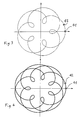
- the knife 42 can describe several turns, depending on the reduction due to the ratio between the number of teeth of the satellite pinion 44 and the wheel toothed 46. Note further that, depending on the ratio chosen, the knife will not present itself to the cutting point in front of the end 41 only after a certain number of turns of the planet carrier 47.
- FIG. 3 illustrates the trajectory of the knife 42 in the case where it returns to the point of cutting every two turns of the planet carrier 47 and
- FIG. 4 illustrates the trajectory of the knife 42 in the event that it returns to the cutting point every three turns of the satellite carrier 47.
- the cut stops the wire 3 only for an instant as brief as possible. We therefore has no problem of wire accumulation continuing to be pushed by the rollers 20 and 21 upstream of the knife 42.
- the cutting proposed by the invention is so rapid that the guide tubular 40, was only by the game allowing the sliding of the wire 3, can contain momentarily the quantity of wire 3 which continues to be propelled by the rollers 20, 21.
- the section 30 of wire no longer benefits from the motorization by the rollers 20 and 21 installed upstream. This is why, preferably, the gap between the cutting point and the laying point so that the last end of the wire 3 created by the previous cut joins the point of laying on the support 1 just before the wire 3 is cut again.
- the movement of the section 30 is caused by the rotation of the support 1 on which he adheres.
- it preferably the distance between the contact point of the roller on the support and the cutting point corresponding to the maximum length of the sections. Note that if the kinetic energy accumulated by the sections is sufficient, it is possible ensure the operation of the machine described even if the distance between the point of contact of the roller on the support and the cutting point is greater than the maximum mentioned above.
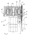
- FIG. 5 and 6 there is shown a cutting device 14 constituting another mode of embodiment which can replace the cutting device 4 of FIG. 1.
- the cutting device 14 is mounted on a laying head 134. It includes a guide comparable to the guide 40, along from which said reinforcement is introduced, the end 141 of said guide defining a cutting point of the reinforcement.
- a knife 142 mounted on a rotating disc 143, rotated by a pinion 145 (via a belt), pinion 145 being fixed in rotation with a cam 146.
- a bar 147 supports the axis 144 of the disc 143 and the axis 148 of the assembly formed by the cam 146 and the pinion 145.
- the bar 147 is guided by rollers 137 mounted on the laying head 134.
- the cam 146 and the disc 143 are thus mounted to slide relative to the laying head. 134.
- the cam has a boss 149, and it cooperates with a pin 136 secured to the head 134.
- the knife 142 is driven continuously at high speed. He is in position inactive in Figure 6 and, at the desired time, advances to wire 3 to cut it (see Figure 5).
- the cutting device 14 is therefore arranged so that the knife 142 describes a trajectory which crosses the reinforcement at said cutting point when the boss 149 of the cam is engaged on the counter (136).
Abstract
Description
La présente invention concerne la fabrication des pneumatiques. Plus précisément, elle se rapporte à la fabrication des armatures de renforcement, notamment pour le sommet du pneumatique.The present invention relates to the manufacture of tires. More specifically, it relates to the manufacture of reinforcement, in particular for the top of the pneumatic.
On sait que les pneumatiques sont usuellement renforcés par des monofilaments ou des câbles ou autres assemblages de brins unitaires, que l'on désignera de façon générique par le terme "renfort" dans la présente demande. Un paramètre d'architecture important est l'angle que forment ces renforts par rapport à une référence normalisée bien connue des hommes du métier, à savoir le plan médian perpendiculaire à l'axe de rotation du pneumatique. La présente demande de brevet se rapporte notamment aux renforcements à zéro degré, quelle que soit la localisation précise de ces renforcements dans le pneumatique. Les renforcements peuvent être réalisés en déposant un seul fil individuellement ou en déposant quelques fils simultanément, par groupe de fils parallèles, par exemple une dizaine de fils parallèles. Notons que le terme « fil » vise indistinctement un brin unique comme un monofilament, ou un assemblage de brins unitaires comme un câble, et le terme « renfort » vise aussi indistinctement un fil unique, ou un groupe de fils parallèles. Les fils peuvent être nus ou pré revêtus de caoutchouc ou de toute autre matière apte à rendre les fils collants.We know that tires are usually reinforced with monofilaments or cables or other assemblies of unitary strands, which will be designated generically by the term "reinforcement" in the present application. An important architectural parameter is the angle that form these reinforcements compared to a standard reference well known to men of the profession, namely the median plane perpendicular to the axis of rotation of the tire. The the present patent application relates in particular to zero-degree reinforcements, which that is the precise location of these reinforcements in the tire. Reinforcements can be made by depositing a single wire individually or by depositing a few wires simultaneously, by group of parallel wires, for example a dozen parallel wires. Note that the term "wire" is used to refer to a single strand, such as a monofilament, or an assembly of unitary strands like a cable, and the term “reinforcement” also refers to without distinction a single wire, or a group of parallel wires. The wires can be bare or pre coated with rubber or any other material capable of making the wires sticky.
L'état de la technique connaít de nombreux exemples d'utilisation de renforts à zéro degré pour renforcer les flancs ou le sommet des pneumatiques. Mais une telle implantation a pour inconvénient majeur que l'ébauche de pneu en cours de fabrication ne se prête plus ou se prête mal à la ou aux conformations pendant les phases ultérieures de la fabrication du pneu.The state of the art knows many examples of the use of reinforcements at zero degrees to strengthen the sidewalls or the top of the tires. But such an establishment has for major drawback that the tire blank during manufacture no longer lends itself or lends itself harm to the conformation (s) during the later stages of tire manufacturing.
Afin d'apporter une solution à ces problèmes de conformation, une technique bien connue consiste à couper les fils à zéro degré en tronçons. On convient d'appeler "tronçon" le morceau de fil compris entre les coupes. Le brevet US 4,791,973 illustre cette technique. Il y est décrit un pneumatique comportant une ceinture incluant des fils à zéro degré. Ceux-ci ne sont pas continus circonférentiellement. Un certain nombre de tronçons se succèdent les uns à la suite des autres le long d'un périmètre. In order to provide a solution to these conformation problems, a well known technique consists of cutting the wires at zero degrees into sections. We agree to call "section" the piece of wire between the cuts. US Patent 4,791,973 illustrates this technique. It is described there a tire comprising a belt including wires at zero degrees. These are not circumferentially continuous. A number of sections follow one after the other others along a perimeter.
Comme il est très difficile de couper à très grande vitesse un renfort en défilement rapide, ce principe conduit à des cadences de pose de renforts à zéro degré beaucoup trop lentes, en particulier si l'on dépose un seul fil à la fois et non pas un groupe de fils parallèles, en bobinant le renfort sur l'ébauche en cours de confection tout en déplaçant une tête de pose du renfort transversalement. Si l'on envisage de déposer une seule nappe, par exemple en enroulant ladite nappe en un tour sur l'ébauche crue pendant son assemblage, il faut préparer à l'avance des incisions souhaitées sur ladite nappe, et cette méthode oblige à prévoir un certain recouvrement à la soudure afin d'assurer la reprise des efforts circonférentiels d'extension.As it is very difficult to cut a fast-moving reinforcement at very high speed, this principle leads to much too slow rates of laying reinforcements at zero degrees, in especially if you put only one wire at a time and not a group of parallel wires, winding the reinforcement on the blank being made while moving a laying head of the transverse reinforcement. If you plan to deposit a single tablecloth, for example in winding said sheet in one turn on the raw blank during its assembly, it is necessary to prepare for the advance of the desired incisions on said sheet, and this method requires to provide a certain overlap in the weld to ensure the recovery of the circumferential extension forces.
L'invention a pour objectif de proposer des moyens de coupe très rapides, que ces coupes soient fréquentes comme dans le cas décrit ci-dessus ou que la coupe intervienne seulement à la fin de l'opération concernant un pneumatique, comme dans le cas de renforts à zéro degré en fil continu. L'invention permet d'envisager dans de bonnes conditions de performance industrielle la pose de tronçons de fils pour n'importe quelle application de renforcement.The invention aims to provide very fast cutting means, that these cuts are frequent as in the case described above or that the cutting occurs only at the end of the operation concerning a tire, as in the case of reinforcements at zero degrees in continuous wire. The invention makes it possible to envisage in good performance conditions industrial laying of wire sections for any reinforcement application.
L'invention propose un procédé de fabrication d'un renforcement pour pneumatique, ledit renforcement étant constitué à partir d'un renfort délivré par des moyens d'alimentation imposant au renfort un mouvement d'avance à une vitesse linéaire donnée dans la direction longitudinale du renfort, consistant à déposer des tronçons dudit renfort sur un support, à retenir lesdits tronçons sur le support par adhérence sur celui-ci, lesdits tronçons étant prélevés en aval des moyens d'alimentation de la façon suivante :
- faire coulisser ledit renfort dans un guide tubulaire dont l'orifice aval définit un point de coupe,
- entraíner au moyen d'une commande par arbre rotatif un couteau selon une trajectoire fermée quelconque amenant le couteau à passer dans l'environnement du point de coupe, le couteau étant actif au point de coupe à la demande.
- sliding said reinforcement in a tubular guide whose downstream orifice defines a cutting point,
- drive by means of a rotary shaft control a knife along any closed path causing the knife to pass into the environment of the cutting point, the knife being active at the cutting point on demand.
La coupe à la demande peut se faire par un actionneur adapté. En variante, la construction de la commande est telle que le couteau est actif au point de coupe tous les n passages, n supérieur ou égal à deux. Cutting on demand can be done by a suitable actuator. Alternatively, the construction of the command is such that the knife is active at the cutting point every n passages, n greater than or equal to two.
L'invention propose de faire tourner un couteau à très haute vitesse et, par une cinématique appropriée, de faire en sorte que le couteau ne soit pas actif à chaque passage près du renfort. Dans la mise en oeuvre décrite ci-dessous, l'invention exploite l'agencement connu en soi des pignons satellites existant dans certains réducteurs. Cela permet de faire décrire au couteau une trajectoire comprise dans un plan.The invention proposes to rotate a knife at very high speed and, by kinematics ensure that the knife is not active every time you pass the reinforcement. In the implementation described below, the invention exploits the arrangement known per se of satellite pinions existing in certain reducers. This allows to describe with a knife a trajectory included in a plane.
C'est ainsi que l'invention propose une machine de fabrication d'un renforcement pour pneumatique, comportant un distributeur de renfort imposant à un renfort un mouvement d'avance à une vitesse linéaire donnée dans la direction longitudinale du renfort, et un dispositif de coupe comprenant :
- un guide tubulaire dans lequel ledit renfort est introduit et dans lequel on le fait coulisser, l'orifice aval dudit guide tubulaire définissant un point de coupe du renfort,
- un couteau monté rotatif autour d'un arbre entraíné en rotation par un pignon satellite en prise sur une roue dentée fixe, le pignon satellite étant entraíné par un porte satellite de façon à ce que le pignon satellite roule sur la roue dentée fixe, ledit dispositif de coupe étant agencé de façon à ce que le couteau décrive une trajectoire qui croise le renfort audit point de coupe,
- a tubular guide into which said reinforcement is inserted and in which it is made to slide, the downstream orifice of said tubular guide defining a cutting point of the reinforcement,
- a knife mounted to rotate around a shaft driven in rotation by a satellite pinion engaged on a fixed toothed wheel, the satellite pinion being driven by a satellite holder so that the satellite pinion rolls on the fixed toothed wheel, said device being cut so that the knife follows a trajectory which crosses the reinforcement at said cutting point,
L'invention permet une fabrication directe sur un support, à partir de bobines dans lesquelles le renfort est prélevé en continu. Le support dont il est question peut être une forme de révolution sur laquelle on fabrique un bloc sommet, ou un tambour qui supporte le pneu cru en cours de fabrication, ou tout autre support convenable, l'invention ne traitant pas en soi de cet aspect. Pour que le renfort posé reste en place sur le support, il est avantageux que le support soit revêtu d'une couche de caoutchouc cru à laquelle le renfort puisse coller ou adhérer, ou dans laquelle le renfort puisse pénétrer au moins légèrement au fur et à mesure qu'il est amené sur le support. The invention allows direct manufacture on a support, from coils in which the reinforcement is removed continuously. The support in question can be a form of revolution on which we build a crown block, or a drum which supports the raw tire during manufacture, or any other suitable support, the invention not in itself dealing with this aspect. So that the reinforcement placed remains in place on the support, it is advantageous that the support is coated with a layer of raw rubber to which the reinforcement can stick or adhere, or in which the reinforcement can penetrate at least slightly as and that it is brought on the support.
L'invention sera mieux comprise par la description qui va suivre, donnée à titre non limitatif,
en se référant au dessin annexé sur lequel :
A la figure 1, on aperçoit un support 1 sur lequel on fabrique un renforcement. Ce support
pourrait être constitué par tout type de forme définissant la surface sur laquelle on va disposer
les tronçons de fils constituant le renforcement, comme par exemple une membrane armée
gonflable, ou une forme réglable en diamètre du genre de celle utilisée dans les machines de
confection de bloc sommet imposant un profil purement cylindrique, ou une forme galbée
transversalement. Le support 1 est déjà revêtu de tous les constituants qu'il doit recevoir avant
l'addition du renforcement à zéro degré. Le support 1 est entraíné en rotation dans le sens
indiqué par la flèche A.In Figure 1, we can see a
On voit un distributeur 2 de renfort adapté spécifiquement pour délivrer un seul fil 3, sans que
cela ne puisse être interprété comme limitant la portée de l'invention, qui s'étend à tout type
de renforts. Le fil 3 est dévidé hors d'une bobine (non représentée). Le fil 3 est engagé sur
différentes poulies d'un système de compas 32 lui permettant, à partir d'un point fixe dans
l'espace (poulie 33), de rejoindre une tête de pose 34 mobile dans l'espace. Un robot 35 à trois
axes (Y, Z, α) permet d'assurer la présentation correcte du fil 3 à tout endroit de la surface du
support 1, même quand le support est de forme non cylindrique.We see a
Sur la tête de pose, le fil 3 est motorisé par deux galets 20, 21 entre lesquels il est pincé. Le
galet 20 est entraíné par un moteur (non représenté) d'avance du fil 3. Bien entendu, comme
cela est devenu classique, le moteur d'avance peut comporter un codeur ou un résolveur. Il est
ainsi possible d'imposer au fil 3 une avance linéaire bien précise tout en connaissant en
continu la mesure précise de la quantité de fil 3 délivrée aux organes de la machine disposés
en aval.On the laying head, the
A la sortie des galets 20, 21, le fil 3 est introduit dans un dispositif de coupe 4, installé sur la
tête de pose 34. Tout comme le distributeur de fil, le dispositif de coupe est, dans cet exemple,
adapté à un renfort constitué par un seul fil. En aval du dispositif de coupe 4, de préférence,
un galet d'applique 5 presse le fil 3 contre le support 1 pour le faire pénétrer légèrement dans
le caoutchouc dont est revêtu le support 1. Le galet d'applique 5 est représenté fixe au dessin
joint, bien qu'il puisse être monté sur une suspension élastique dans la direction radiale par
rapport au support.At the outlet of the
A la figure 2, on voit un guide tubulaire 40, dont l'extrémité renforcée 41 détermine la
position du point de coupe et maintient le fil 3 lorsqu'il est tranché. Un couteau 42 est monté
sur un disque 43 solidaire d'un pignon satellite 44 (le disque 43 et le pignon satellite 44 étant
montés rotatifs sur un même arbre 45). Le pignon satellite 44 est en prise avec une roue
dentée 46 montée fixe, c'est à dire non tournante (ce pourrait être indifféremment une
couronne dentée intérieurement ou extérieurement, ou toute autre disposition convenable).
L'arbre 45 est monté sur un porte-satellite 47 entraíné en rotation par un moteur de coupe 48.
Le dispositif 4 peut comporter un ou plusieurs autres disques auxiliaires non actifs tels que le
disque auxiliaire 49, avec pignon(s) satellite(s) correspondant(s), notamment pour des
questions d'équilibrage.In FIG. 2, we see a
Ainsi, à chaque tour du porte-satellite 47, le couteau 42 peut décrire plusieurs tours, selon la
démultiplication due au rapport entre le nombre de dents du pignon satellite 44 et de la roue
dentée 46. Remarquons en outre que, selon le rapport choisi, le couteau ne se présentera au
point de coupe devant l'extrémité 41 que au bout d'un certain nombre de tours du porte-satellite
47. La figure 3 illustre la trajectoire du couteau 42 dans le cas où il repasse au point
de coupe tous les deux tours du porte-satellite 47 et la figure 4 illustre la trajectoire du couteau
42 dans le cas où il repasse au point de coupe tous les trois tours du porte-satellite 47. Thus, at each turn of the planet carrier 47, the
Grâce à cet effet de démultiplication et au choix possible du nombre de tours du porte-satellite
entre deux actions du couteau 42, il est possible de concilier de grandes vitesses du couteau 42
avec une vitesse de défilement du fil relativement faible. On peut donc adapter très facilement
la longueur des tronçons 30 de fil posés sur le support 1 en choisissant judicieusement le
rapport de démultiplication dont il a été question ci-dessus. En outre, la coupe à grande vitesse
facilite la coupe de fibres plus difficiles à couper comme par exemple l'aramide.Thanks to this multiplication effect and the possible choice of the number of revolutions of the planet carrier
between two actions of the
Il est important de noter que la coupe n'arrête le fil 3 qu'un instant aussi bref que possible. On
n'a donc pas de problème d'accumulation de fil continuant à être poussé par les galets 20 et
21 en amont du couteau 42. Bien que, au moment où le fil 3 est sectionné, celui-ci se trouve
immobilisé un très bref instant, la coupe proposée par l'invention est si rapide que le guide
tubulaire 40, ne fusse que par le jeu permettant le coulissement du fil 3, peut contenir
momentanément la quantité de fil 3 qui continue à être propulsé par les galets 20, 21.It is important to note that the cut stops the
Après la coupe, le tronçon 30 de fil ne bénéficie plus de la motorisation par les galets 20 et 21
installée en amont. C'est pourquoi de préférence on règle l'écart entre le point de coupe et le
point de pose de façon à ce que la dernière extrémité du fil 3 créée par la coupe précédente
rejoigne le point de pose sur le support 1 juste avant que le fil 3 ne soit à nouveau coupé.
Après la coupe, le mouvement du tronçon 30 est causé par la rotation du support 1 sur lequel
il adhère. Afin d'assurer de façon positive l'avance des tronçons de fil libérés par la coupe, il
convient de préférence que la distance entre le point de contact du galet d'applique sur le
support et le point de coupe correspondant au maximum à la longueur des tronçons.
Soulignons que si l'énergie cinétique accumulée par les tronçons est suffisante, il est possible
d'assurer le fonctionnement de la machine décrite même si la distance entre le point de
contact du galet d'applique sur le support et le point de coupe est supérieure au maximum
évoqué ci-dessus.After cutting, the
Au figures 5 et 6, on a représenté un dispositif de coupe 14 constituant un autre mode de
réalisation pouvant se substituer au dispositif de coupe 4 de la figure 1. Le dispositif de coupe
14 est monté sur une tête de pose 134. Il comporte un guide comparable au guide 40, le long
duquel ledit renfort est introduit, l'extrémité 141 dudit guide définissant un point de coupe du
renfort. On voit un couteau 142 monté sur un disque 143 rotatif, entraíné en rotation par un
pignon 145 (via une courroie), le pignon 145 étant solidaire en rotation d'une came 146. Un
barreau 147 supporte l'axe 144 du disque 143 et l'axe 148 de l'ensemble formé par la came
146 et le pignon 145. Le barreau 147 est guidé par des galets 137 montés sur la tête de pose
134. La came 146 et le disque 143 sont ainsi montés coulissant par rapport à la tête de pose
134. La came comporte un bossage 149, et elle coopère avec un pion 136 solidaire de la tête
de pose 134. Le couteau 142 est entraíné en permanence à vitesse élevée. Il est en position
inactive à la figure 6 et, au moment voulu, avance vers le fil 3 pour le couper (voir figure 5).
Le dispositif de coupe 14 est donc agencé de façon à ce que le couteau 142 décrive une
trajectoire qui croise le renfort audit point de coupe lorsque le bossage 149 de la came est
engagé sur le pion (136).In Figures 5 and 6, there is shown a
A la lumière de cette description, l'homme du métier pourra facilement réaliser des variantes et utiliser des adaptations sans sortir du cadre de la présente invention. On peut souhaiter par exemple poser des fils en matière textile. Tous les fils ne présentant aucune résistance à la compression doivent impérativement être maintenus bien tendus. On peut utiliser, partout où cela est nécessaire, une propulsion pneumatique du genre de celle apparaissant sous la référence 56 dans le brevet US 3 894 906.In the light of this description, a person skilled in the art can easily produce variants and use adaptations without departing from the scope of the present invention. We can wish by example install textile threads. All wires showing no resistance to compression must be kept tight. We can use, wherever this is necessary, pneumatic propulsion of the kind appearing under the reference 56 in US Patent 3,894,906.
Claims (7)
Applications Claiming Priority (2)
| Application Number | Priority Date | Filing Date | Title |
|---|---|---|---|
| FR0005071 | 2000-04-18 | ||
| FR0005071 | 2000-04-18 |
Publications (3)
| Publication Number | Publication Date |
|---|---|
| EP1147864A2 true EP1147864A2 (en) | 2001-10-24 |
| EP1147864A3 EP1147864A3 (en) | 2003-05-07 |
| EP1147864B1 EP1147864B1 (en) | 2005-07-06 |
Family
ID=8849438
Family Applications (1)
| Application Number | Title | Priority Date | Filing Date |
|---|---|---|---|
| EP01108701A Expired - Lifetime EP1147864B1 (en) | 2000-04-18 | 2001-04-06 | High speed cutting device for cutting reinforcing elements for tyres |
Country Status (5)
| Country | Link |
|---|---|
| US (1) | US6969438B2 (en) |
| EP (1) | EP1147864B1 (en) |
| JP (1) | JP4755356B2 (en) |
| AT (1) | ATE299079T1 (en) |
| DE (1) | DE60111798T2 (en) |
Cited By (3)
| Publication number | Priority date | Publication date | Assignee | Title |
|---|---|---|---|---|
| EP1918088A1 (en) * | 2006-11-02 | 2008-05-07 | Societe de Technologie Michelin | Device and method of guiding a cord |
| CN102688959A (en) * | 2012-06-19 | 2012-09-26 | 曲海涛 | Simple steel bar straightening and shearing machine |
| CN110238322A (en) * | 2019-05-17 | 2019-09-17 | 安徽明洋电子有限公司 | One kind double charactron shearing-foot device in bulk and its application method |
Families Citing this family (11)
| Publication number | Priority date | Publication date | Assignee | Title |
|---|---|---|---|---|
| DE602005008708D1 (en) * | 2004-01-27 | 2008-09-18 | Michelin Soc Tech | METHOD AND DEVICE FOR PRODUCING A TIRE REINFORCEMENT |
| FR2879500A1 (en) * | 2004-12-22 | 2006-06-23 | Michelin Soc Tech | METHOD AND DEVICE FOR THE MANUFACTURE AND INSTALLATION OF A CIRCONFERENTIAL REINFORCEMENT FOR A PNEUMATIC AND TIRE OBTAINED BY SAID METHOD |
| US7740039B2 (en) * | 2005-12-01 | 2010-06-22 | The Goodyear Tire & Rubber Company | Cord cutting mechanism and method for a tire cord applicator head |
| CN100423867C (en) * | 2006-11-17 | 2008-10-08 | 宁波长城精工实业有限公司 | Tape zero-cutting machine |
| US20080314216A1 (en) * | 2007-06-20 | 2008-12-25 | Andres Ignacio Delgado | Tire cord cutting apparatus |
| EP2006078B1 (en) * | 2007-06-20 | 2011-05-25 | The Goodyear Tire & Rubber Company | Tire cord cutting apparatus and method for single line tire ply construction |
| US20080314524A1 (en) * | 2007-06-20 | 2008-12-25 | Andres Ignacio Delgado | Method for single line tire ply construction |
| JP2009061717A (en) * | 2007-09-07 | 2009-03-26 | Bridgestone Corp | Manufacturing equipment of tire reinforcing band, and manufacturing process of tire reinforcing band |
| US10307980B2 (en) * | 2013-02-20 | 2019-06-04 | The Goodyear Tire & Rubber Company | Tire building applicator members and systems |
| US20150041067A1 (en) * | 2013-08-07 | 2015-02-12 | The Goodyear Tire & Rubber Company | Component applying/cutting apparatus for a tire building machine |
| CN104475553B (en) * | 2014-11-26 | 2016-07-27 | 揭阳榕申卷尺有限公司 | One returns coil spring fully automatic forming machine |
Citations (5)
| Publication number | Priority date | Publication date | Assignee | Title |
|---|---|---|---|---|
| US4914997A (en) * | 1987-07-22 | 1990-04-10 | G.D. Societa Per Azioni | Transverse cutting device for cutting into lengths a strip traveling continuously along a predetermined path |
| US4941378A (en) * | 1988-10-24 | 1990-07-17 | General Motors Corporation | Method and apparatus for rapid repetitive cutting |
| US5281289A (en) * | 1991-06-17 | 1994-01-25 | Sedepro | Process for the manufacturing of a tire and machines for the carrying out of the process |
| EP0745462A2 (en) * | 1995-06-01 | 1996-12-04 | Bellaform Extrusionstechnik Gmbh | Device for the cutting into lengths or slotting of continuously moving elongated material |
| US5655427A (en) * | 1994-05-25 | 1997-08-12 | Ferag Ag | Stapling device with rotary cutting element |
Family Cites Families (5)
| Publication number | Priority date | Publication date | Assignee | Title |
|---|---|---|---|---|
| US3894906A (en) * | 1973-06-01 | 1975-07-15 | Nat Standard Co | Apparatus for making tire breakers |
| US4640164A (en) * | 1985-05-02 | 1987-02-03 | Essex Group, Inc. | High speed wire cutter |
| GB8708977D0 (en) * | 1987-04-14 | 1987-05-20 | Goodyear Tire & Rubber | Reinforcing plies for tyres |
| FR2694519A1 (en) * | 1992-08-07 | 1994-02-11 | Sedepro | Method of manufacturing a tire and machine for manufacturing a crown reinforcement for a tire. |
| US6032560A (en) * | 1997-10-24 | 2000-03-07 | Morgan Construction Company | High speed trimming shear |
-
2001
- 2001-04-06 DE DE60111798T patent/DE60111798T2/en not_active Expired - Lifetime
- 2001-04-06 AT AT01108701T patent/ATE299079T1/en not_active IP Right Cessation
- 2001-04-06 EP EP01108701A patent/EP1147864B1/en not_active Expired - Lifetime
- 2001-04-18 US US09/837,523 patent/US6969438B2/en not_active Expired - Fee Related
- 2001-04-18 JP JP2001120197A patent/JP4755356B2/en not_active Expired - Fee Related
Patent Citations (5)
| Publication number | Priority date | Publication date | Assignee | Title |
|---|---|---|---|---|
| US4914997A (en) * | 1987-07-22 | 1990-04-10 | G.D. Societa Per Azioni | Transverse cutting device for cutting into lengths a strip traveling continuously along a predetermined path |
| US4941378A (en) * | 1988-10-24 | 1990-07-17 | General Motors Corporation | Method and apparatus for rapid repetitive cutting |
| US5281289A (en) * | 1991-06-17 | 1994-01-25 | Sedepro | Process for the manufacturing of a tire and machines for the carrying out of the process |
| US5655427A (en) * | 1994-05-25 | 1997-08-12 | Ferag Ag | Stapling device with rotary cutting element |
| EP0745462A2 (en) * | 1995-06-01 | 1996-12-04 | Bellaform Extrusionstechnik Gmbh | Device for the cutting into lengths or slotting of continuously moving elongated material |
Cited By (5)
| Publication number | Priority date | Publication date | Assignee | Title |
|---|---|---|---|---|
| EP1918088A1 (en) * | 2006-11-02 | 2008-05-07 | Societe de Technologie Michelin | Device and method of guiding a cord |
| FR2908072A1 (en) * | 2006-11-02 | 2008-05-09 | Michelin Soc Tech | DEVICE AND METHOD FOR GUIDING A WIRE |
| US7976660B2 (en) | 2006-11-02 | 2011-07-12 | Michelin Recherche Et Technique S.A. | Device and method for guiding a thread |
| CN102688959A (en) * | 2012-06-19 | 2012-09-26 | 曲海涛 | Simple steel bar straightening and shearing machine |
| CN110238322A (en) * | 2019-05-17 | 2019-09-17 | 安徽明洋电子有限公司 | One kind double charactron shearing-foot device in bulk and its application method |
Also Published As
| Publication number | Publication date |
|---|---|
| DE60111798T2 (en) | 2006-04-20 |
| DE60111798D1 (en) | 2005-08-11 |
| JP4755356B2 (en) | 2011-08-24 |
| EP1147864A3 (en) | 2003-05-07 |
| ATE299079T1 (en) | 2005-07-15 |
| US6969438B2 (en) | 2005-11-29 |
| EP1147864B1 (en) | 2005-07-06 |
| US20020003020A1 (en) | 2002-01-10 |
| JP2001347577A (en) | 2001-12-18 |
Similar Documents
| Publication | Publication Date | Title |
|---|---|---|
| EP1147864B1 (en) | High speed cutting device for cutting reinforcing elements for tyres | |
| CA2071445C (en) | Tire fabrication process, and machines for implementing said process | |
| EP0580055B1 (en) | Process and apparatus for arranging on a core a single reinforcing wire in the manufacturing of tire carcasses | |
| EP1513673B1 (en) | Device and method for applying a strip to a rotary surface | |
| EP0582215B1 (en) | Method for manufacturing tires and apparatus for manufacturing a crown reinforcement for tires | |
| EP0248301B1 (en) | Method and apparatus for making a reinforcement for a tyre | |
| EP1517781B1 (en) | Device for producing a reinforcing structure for a tyre, comprising a strip turning mechanism | |
| EP0281511B1 (en) | Thread-cutting apparatus | |
| EP1231050B1 (en) | Swing arm apparatus for manufacturing a tyre reinforcing structure using a single thread | |
| EP0519295B1 (en) | Method for the production of a tyre and apparatus for the implementation of the method | |
| EP3880455B1 (en) | System for cutting strips using helical knives and corresponding cutting method | |
| CA2320861A1 (en) | Autonomous strip laying device | |
| EP1513672B1 (en) | System for producing a reinforcing structure for a tyre with volumetric control of the die | |
| EP1711335B1 (en) | Method and device for producing a tyre reinforcement | |
| EP1147865A2 (en) | Apparatus for cutting a wire | |
| EP1426169B1 (en) | Apparatus for the manufacture of a reinforcing element for large-dimension tyres | |
| CH426241A (en) | Process for manufacturing tires, tire manufactured according to this process and apparatus for implementing this process | |
| EP1824666B1 (en) | Appliance for producing a reinforcement for a pneumatic tyre | |
| FR3113382A1 (en) | Management of Rolling and Cutting of Rubber Product Ply in a Tire Manufacturing Facility | |
| FR3131247A1 (en) | FIBER APPLICATION MACHINE EQUIPPED WITH A VOLTAGE LIMITER SYSTEM | |
| EP0704295A1 (en) | Wire reinforcement of a rubber matrix | |
| WO2016102538A1 (en) | Device and method for depositing a crimped wire on a receiving surface |
Legal Events
| Date | Code | Title | Description |
|---|---|---|---|
| PUAI | Public reference made under article 153(3) epc to a published international application that has entered the european phase |
Free format text: ORIGINAL CODE: 0009012 |
|
| AK | Designated contracting states |
Kind code of ref document: A2 Designated state(s): AT BE CH CY DE DK ES FI FR GB GR IE IT LI LU MC NL PT SE TR |
|
| AX | Request for extension of the european patent |
Free format text: AL;LT;LV;MK;RO;SI |
|
| PUAL | Search report despatched |
Free format text: ORIGINAL CODE: 0009013 |
|
| AK | Designated contracting states |
Designated state(s): AT BE CH CY DE DK ES FI FR GB GR IE IT LI LU MC NL PT SE TR |
|
| AX | Request for extension of the european patent |
Extension state: AL LT LV MK RO SI |
|
| 17P | Request for examination filed |
Effective date: 20031107 |
|
| AKX | Designation fees paid |
Designated state(s): AT BE CH CY DE DK ES FI FR GB GR IE IT LI LU MC NL PT SE TR |
|
| 17Q | First examination report despatched |
Effective date: 20040212 |
|
| GRAP | Despatch of communication of intention to grant a patent |
Free format text: ORIGINAL CODE: EPIDOSNIGR1 |
|
| RAP1 | Party data changed (applicant data changed or rights of an application transferred) |
Owner name: SEDEPRO |
|
| GRAS | Grant fee paid |
Free format text: ORIGINAL CODE: EPIDOSNIGR3 |
|
| GRAA | (expected) grant |
Free format text: ORIGINAL CODE: 0009210 |
|
| AK | Designated contracting states |
Kind code of ref document: B1 Designated state(s): AT BE CH CY DE DK ES FI FR GB GR IE IT LI LU MC NL PT SE TR |
|
| PG25 | Lapsed in a contracting state [announced via postgrant information from national office to epo] |
Ref country code: IE Free format text: LAPSE BECAUSE OF FAILURE TO SUBMIT A TRANSLATION OF THE DESCRIPTION OR TO PAY THE FEE WITHIN THE PRESCRIBED TIME-LIMIT Effective date: 20050706 Ref country code: FI Free format text: LAPSE BECAUSE OF FAILURE TO SUBMIT A TRANSLATION OF THE DESCRIPTION OR TO PAY THE FEE WITHIN THE PRESCRIBED TIME-LIMIT Effective date: 20050706 Ref country code: AT Free format text: LAPSE BECAUSE OF FAILURE TO SUBMIT A TRANSLATION OF THE DESCRIPTION OR TO PAY THE FEE WITHIN THE PRESCRIBED TIME-LIMIT Effective date: 20050706 |
|
| REG | Reference to a national code |
Ref country code: GB Ref legal event code: FG4D Free format text: NOT ENGLISH |
|
| REG | Reference to a national code |
Ref country code: CH Ref legal event code: EP |
|
| REG | Reference to a national code |
Ref country code: IE Ref legal event code: FG4D Free format text: LANGUAGE OF EP DOCUMENT: FRENCH |
|
| REF | Corresponds to: |
Ref document number: 60111798 Country of ref document: DE Date of ref document: 20050811 Kind code of ref document: P |
|
| PG25 | Lapsed in a contracting state [announced via postgrant information from national office to epo] |
Ref country code: DK Free format text: LAPSE BECAUSE OF FAILURE TO SUBMIT A TRANSLATION OF THE DESCRIPTION OR TO PAY THE FEE WITHIN THE PRESCRIBED TIME-LIMIT Effective date: 20051006 Ref country code: SE Free format text: LAPSE BECAUSE OF FAILURE TO SUBMIT A TRANSLATION OF THE DESCRIPTION OR TO PAY THE FEE WITHIN THE PRESCRIBED TIME-LIMIT Effective date: 20051006 Ref country code: GR Free format text: LAPSE BECAUSE OF FAILURE TO SUBMIT A TRANSLATION OF THE DESCRIPTION OR TO PAY THE FEE WITHIN THE PRESCRIBED TIME-LIMIT Effective date: 20051006 |
|
| PG25 | Lapsed in a contracting state [announced via postgrant information from national office to epo] |
Ref country code: ES Free format text: LAPSE BECAUSE OF FAILURE TO SUBMIT A TRANSLATION OF THE DESCRIPTION OR TO PAY THE FEE WITHIN THE PRESCRIBED TIME-LIMIT Effective date: 20051017 |
|
| GBT | Gb: translation of ep patent filed (gb section 77(6)(a)/1977) | ||
| PG25 | Lapsed in a contracting state [announced via postgrant information from national office to epo] |
Ref country code: PT Free format text: LAPSE BECAUSE OF FAILURE TO SUBMIT A TRANSLATION OF THE DESCRIPTION OR TO PAY THE FEE WITHIN THE PRESCRIBED TIME-LIMIT Effective date: 20051212 |
|
| REG | Reference to a national code |
Ref country code: IE Ref legal event code: FD4D |
|
| PG25 | Lapsed in a contracting state [announced via postgrant information from national office to epo] |
Ref country code: BE Free format text: LAPSE BECAUSE OF NON-PAYMENT OF DUE FEES Effective date: 20060430 Ref country code: LI Free format text: LAPSE BECAUSE OF NON-PAYMENT OF DUE FEES Effective date: 20060430 Ref country code: CH Free format text: LAPSE BECAUSE OF NON-PAYMENT OF DUE FEES Effective date: 20060430 Ref country code: MC Free format text: LAPSE BECAUSE OF NON-PAYMENT OF DUE FEES Effective date: 20060430 |
|
| PGFP | Annual fee paid to national office [announced via postgrant information from national office to epo] |
Ref country code: IT Payment date: 20060430 Year of fee payment: 6 |
|
| PLBE | No opposition filed within time limit |
Free format text: ORIGINAL CODE: 0009261 |
|
| STAA | Information on the status of an ep patent application or granted ep patent |
Free format text: STATUS: NO OPPOSITION FILED WITHIN TIME LIMIT |
|
| 26N | No opposition filed |
Effective date: 20060407 |
|
| NLS | Nl: assignments of ep-patents |
Owner name: MANUFACTURE FRANEAISE DES PNEUMATIQUES MICHELIN Effective date: 20060622 |
|
| REG | Reference to a national code |
Ref country code: FR Ref legal event code: TP |
|
| REG | Reference to a national code |
Ref country code: CH Ref legal event code: PL |
|
| REG | Reference to a national code |
Ref country code: GB Ref legal event code: 732E |
|
| BERE | Be: lapsed |
Owner name: SEDEPRO Effective date: 20060430 |
|
| PG25 | Lapsed in a contracting state [announced via postgrant information from national office to epo] |
Ref country code: LU Free format text: LAPSE BECAUSE OF NON-PAYMENT OF DUE FEES Effective date: 20060406 Ref country code: TR Free format text: LAPSE BECAUSE OF FAILURE TO SUBMIT A TRANSLATION OF THE DESCRIPTION OR TO PAY THE FEE WITHIN THE PRESCRIBED TIME-LIMIT Effective date: 20050706 |
|
| PG25 | Lapsed in a contracting state [announced via postgrant information from national office to epo] |
Ref country code: CY Free format text: LAPSE BECAUSE OF FAILURE TO SUBMIT A TRANSLATION OF THE DESCRIPTION OR TO PAY THE FEE WITHIN THE PRESCRIBED TIME-LIMIT Effective date: 20050706 |
|
| PG25 | Lapsed in a contracting state [announced via postgrant information from national office to epo] |
Ref country code: IT Free format text: LAPSE BECAUSE OF NON-PAYMENT OF DUE FEES Effective date: 20070406 |
|
| PGFP | Annual fee paid to national office [announced via postgrant information from national office to epo] |
Ref country code: GB Payment date: 20100420 Year of fee payment: 10 |
|
| GBPC | Gb: european patent ceased through non-payment of renewal fee |
Effective date: 20110406 |
|
| PG25 | Lapsed in a contracting state [announced via postgrant information from national office to epo] |
Ref country code: GB Free format text: LAPSE BECAUSE OF NON-PAYMENT OF DUE FEES Effective date: 20110406 |
|
| PGFP | Annual fee paid to national office [announced via postgrant information from national office to epo] |
Ref country code: DE Payment date: 20120420 Year of fee payment: 12 Ref country code: NL Payment date: 20120425 Year of fee payment: 12 |
|
| PGFP | Annual fee paid to national office [announced via postgrant information from national office to epo] |
Ref country code: FR Payment date: 20120507 Year of fee payment: 12 |
|
| REG | Reference to a national code |
Ref country code: NL Ref legal event code: V1 Effective date: 20131101 |
|
| PG25 | Lapsed in a contracting state [announced via postgrant information from national office to epo] |
Ref country code: DE Free format text: LAPSE BECAUSE OF NON-PAYMENT OF DUE FEES Effective date: 20131101 |
|
| REG | Reference to a national code |
Ref country code: FR Ref legal event code: ST Effective date: 20131231 |
|
| REG | Reference to a national code |
Ref country code: DE Ref legal event code: R119 Ref document number: 60111798 Country of ref document: DE Effective date: 20131101 |
|
| PG25 | Lapsed in a contracting state [announced via postgrant information from national office to epo] |
Ref country code: FR Free format text: LAPSE BECAUSE OF NON-PAYMENT OF DUE FEES Effective date: 20130430 Ref country code: NL Free format text: LAPSE BECAUSE OF NON-PAYMENT OF DUE FEES Effective date: 20131101 |