EP1513673B1 - Device and method for applying a strip to a rotary surface - Google Patents
Device and method for applying a strip to a rotary surface Download PDFInfo
- Publication number
- EP1513673B1 EP1513673B1 EP03727440A EP03727440A EP1513673B1 EP 1513673 B1 EP1513673 B1 EP 1513673B1 EP 03727440 A EP03727440 A EP 03727440A EP 03727440 A EP03727440 A EP 03727440A EP 1513673 B1 EP1513673 B1 EP 1513673B1
- Authority
- EP
- European Patent Office
- Prior art keywords
- strip
- cords
- transverse displacement
- yarns
- receiving surface
- Prior art date
- Legal status (The legal status is an assumption and is not a legal conclusion. Google has not performed a legal analysis and makes no representation as to the accuracy of the status listed.)
- Expired - Lifetime
Links
Images

Classifications
-
- B—PERFORMING OPERATIONS; TRANSPORTING
- B21—MECHANICAL METAL-WORKING WITHOUT ESSENTIALLY REMOVING MATERIAL; PUNCHING METAL
- B21C—MANUFACTURE OF METAL SHEETS, WIRE, RODS, TUBES, PROFILES OR LIKE SEMI-MANUFACTURED PRODUCTS OTHERWISE THAN BY ROLLING; AUXILIARY OPERATIONS USED IN CONNECTION WITH METAL-WORKING WITHOUT ESSENTIALLY REMOVING MATERIAL
- B21C47/00—Winding-up, coiling or winding-off metal wire, metal band or other flexible metal material characterised by features relevant to metal processing only
- B21C47/26—Special arrangements with regard to simultaneous or subsequent treatment of the material
-
- B—PERFORMING OPERATIONS; TRANSPORTING
- B21—MECHANICAL METAL-WORKING WITHOUT ESSENTIALLY REMOVING MATERIAL; PUNCHING METAL
- B21F—WORKING OR PROCESSING OF METAL WIRE
- B21F1/00—Bending wire other than coiling; Straightening wire
- B21F1/04—Undulating
-
- B—PERFORMING OPERATIONS; TRANSPORTING
- B29—WORKING OF PLASTICS; WORKING OF SUBSTANCES IN A PLASTIC STATE IN GENERAL
- B29C—SHAPING OR JOINING OF PLASTICS; SHAPING OF MATERIAL IN A PLASTIC STATE, NOT OTHERWISE PROVIDED FOR; AFTER-TREATMENT OF THE SHAPED PRODUCTS, e.g. REPAIRING
- B29C70/00—Shaping composites, i.e. plastics material comprising reinforcements, fillers or preformed parts, e.g. inserts
- B29C70/04—Shaping composites, i.e. plastics material comprising reinforcements, fillers or preformed parts, e.g. inserts comprising reinforcements only, e.g. self-reinforcing plastics
- B29C70/28—Shaping operations therefor
- B29C70/30—Shaping by lay-up, i.e. applying fibres, tape or broadsheet on a mould, former or core; Shaping by spray-up, i.e. spraying of fibres on a mould, former or core
- B29C70/32—Shaping by lay-up, i.e. applying fibres, tape or broadsheet on a mould, former or core; Shaping by spray-up, i.e. spraying of fibres on a mould, former or core on a rotating mould, former or core
-
- B—PERFORMING OPERATIONS; TRANSPORTING
- B29—WORKING OF PLASTICS; WORKING OF SUBSTANCES IN A PLASTIC STATE IN GENERAL
- B29C—SHAPING OR JOINING OF PLASTICS; SHAPING OF MATERIAL IN A PLASTIC STATE, NOT OTHERWISE PROVIDED FOR; AFTER-TREATMENT OF THE SHAPED PRODUCTS, e.g. REPAIRING
- B29C70/00—Shaping composites, i.e. plastics material comprising reinforcements, fillers or preformed parts, e.g. inserts
- B29C70/04—Shaping composites, i.e. plastics material comprising reinforcements, fillers or preformed parts, e.g. inserts comprising reinforcements only, e.g. self-reinforcing plastics
- B29C70/28—Shaping operations therefor
- B29C70/30—Shaping by lay-up, i.e. applying fibres, tape or broadsheet on a mould, former or core; Shaping by spray-up, i.e. spraying of fibres on a mould, former or core
- B29C70/38—Automated lay-up, e.g. using robots, laying filaments according to predetermined patterns
- B29C70/382—Automated fiber placement [AFP]
- B29C70/384—Fiber placement heads, e.g. component parts, details or accessories
-
- B—PERFORMING OPERATIONS; TRANSPORTING
- B29—WORKING OF PLASTICS; WORKING OF SUBSTANCES IN A PLASTIC STATE IN GENERAL
- B29D—PRODUCING PARTICULAR ARTICLES FROM PLASTICS OR FROM SUBSTANCES IN A PLASTIC STATE
- B29D30/00—Producing pneumatic or solid tyres or parts thereof
- B29D30/06—Pneumatic tyres or parts thereof (e.g. produced by casting, moulding, compression moulding, injection moulding, centrifugal casting)
- B29D30/08—Building tyres
- B29D30/10—Building tyres on round cores, i.e. the shape of the core is approximately identical with the shape of the completed tyre
- B29D30/16—Applying the layers; Guiding or stretching the layers during application
- B29D30/1621—Applying the layers; Guiding or stretching the layers during application by feeding a continuous band and winding it spirally, i.e. the band is fed without relative movement along the core axis, to form an annular element
-
- B—PERFORMING OPERATIONS; TRANSPORTING
- B29—WORKING OF PLASTICS; WORKING OF SUBSTANCES IN A PLASTIC STATE IN GENERAL
- B29D—PRODUCING PARTICULAR ARTICLES FROM PLASTICS OR FROM SUBSTANCES IN A PLASTIC STATE
- B29D30/00—Producing pneumatic or solid tyres or parts thereof
- B29D30/06—Pneumatic tyres or parts thereof (e.g. produced by casting, moulding, compression moulding, injection moulding, centrifugal casting)
- B29D30/08—Building tyres
- B29D30/10—Building tyres on round cores, i.e. the shape of the core is approximately identical with the shape of the completed tyre
- B29D30/16—Applying the layers; Guiding or stretching the layers during application
- B29D30/1628—Applying the layers; Guiding or stretching the layers during application by feeding a continuous band and winding it helically, i.e. the band is fed while being advanced along the core axis, to form an annular element
-
- B—PERFORMING OPERATIONS; TRANSPORTING
- B29—WORKING OF PLASTICS; WORKING OF SUBSTANCES IN A PLASTIC STATE IN GENERAL
- B29D—PRODUCING PARTICULAR ARTICLES FROM PLASTICS OR FROM SUBSTANCES IN A PLASTIC STATE
- B29D30/00—Producing pneumatic or solid tyres or parts thereof
- B29D30/06—Pneumatic tyres or parts thereof (e.g. produced by casting, moulding, compression moulding, injection moulding, centrifugal casting)
- B29D30/08—Building tyres
- B29D30/20—Building tyres by the flat-tyre method, i.e. building on cylindrical drums
- B29D30/30—Applying the layers; Guiding or stretching the layers during application
- B29D30/3028—Applying the layers; Guiding or stretching the layers during application by feeding a continuous band and winding it helically, i.e. the band is fed while being advanced along the drum axis, to form an annular element
-
- B—PERFORMING OPERATIONS; TRANSPORTING
- B29—WORKING OF PLASTICS; WORKING OF SUBSTANCES IN A PLASTIC STATE IN GENERAL
- B29D—PRODUCING PARTICULAR ARTICLES FROM PLASTICS OR FROM SUBSTANCES IN A PLASTIC STATE
- B29D30/00—Producing pneumatic or solid tyres or parts thereof
- B29D30/06—Pneumatic tyres or parts thereof (e.g. produced by casting, moulding, compression moulding, injection moulding, centrifugal casting)
- B29D30/08—Building tyres
- B29D30/20—Building tyres by the flat-tyre method, i.e. building on cylindrical drums
- B29D30/30—Applying the layers; Guiding or stretching the layers during application
- B29D2030/3064—Details, accessories and auxiliary operations not otherwise provided for
- B29D2030/3078—Details, accessories and auxiliary operations not otherwise provided for the layers being applied being substantially continuous, i.e. not being cut before the application step
Definitions
- the invention relates to an apparatus for applying a reinforcing strip on a rotary receiving surface, in particular for manufacturing tires.
- Such reinforcement may, in particular, be constituted by a web comprising circumferentially wound cords radially disposed on the carcass of the tire.
- This tablecloth is commonly called a "zero degree layer”.
- a textile or metallic cord refers to a unitary yarn or several yarns assembled together to work together or, by extension, a twine.
- the raw tire has been assembled on a cylindrical drum or slightly curved while the baked tire coming out of the baking mold is, with respect to this first form, super-balanced. Therefore, during the conformation, the deformations experienced by the tire will be much greater in the center of said tire than at the level of his shoulders. It is therefore necessary to be able to industrially lay a cord with corrugations of different amplitudes and periods, according to its transverse position so that the formed web has, after press conformation, son oriented substantially zero degrees whatever their transverse position, close to the center or the shoulders.
- EP-A-0 724 949 discloses an apparatus for applying textile or metallic threads on a rotating surface with sinusoidal corrugations.
- Means for displacing the yarns in transverse translation relative to the direction of delivery of the yarns make it possible to obtain such a pose, the amplitude and the period of the sinusoid being controlled by controlling and controlling the rotational speeds of the yarn.
- laying surface, the element delivering the son and the control of the moving means are constituted by a transferable die in the transverse direction, actuated by a motor via a rod attached to a motorized flywheel.
- EP-A-1 208 963 which belongs to the state of the art in accordance with Article 54 (3), provides a first solution to the difficulties mentioned above but remains limited to the laying of a single wire or cable.
- the invention relates to an application apparatus for simultaneous application of several cords in the form of a reinforcing strip and overcoming all the aforementioned drawbacks.
- the apparatus for applying a reinforcing strip to a rotary reception surface comprises means for delivering the strip, means for moving transversely with respect to the receiving surface and means for laying the strip.
- the strip on said receiving surface is characterized in that the delivery means of the strip bring it to the transverse displacement means with an orientation of the plane of the sheet of son or cords of the strip substantially perpendicular to the rotation axis of the rotary reception surface, and that the laying means of the strip, located at the output of the transverse displacement means, rotate 90 ° of the plane of the sheet of son or cords of said strip around an axis parallel to the direction of progression of the strip, in order to arranging the plane of the web of yarns or cords of the strip tangentially with respect to the receiving surface.
- the number of wires or cords deposited simultaneously is generally much smaller than the number of wires constituting the "zero degree layer" once laid. This number is determined as a function of the maximum width of the strip that can be used. This width is set experimentally according to the stiffness of the son or cords and the amplitude of the corrugations, and can range from a few millimeters to several tens of millimeters. For reasons of convenience and standardization, it is generally between 10 and 20 mm.
- the strip comprising at least two and up to a few tens of threads and cords, depending on the diameter and arrangement thereof.
- the application apparatus 1 of a reinforcement strip B on a rotatable receiving surface (2) comprises a body (5), the strip being applied to the receiving surface (2) in one direction substantially perpendicular to the axis of rotation of said surface tangentially to the latter.
- the receiving surface (2) rotates with a controlled circumferential speed which will be designated V2.
- the body (5) carries means (10) for dispensing the strip, transverse displacement means (20, 30) for the strip and finally laying means (40) for this strip on the receiving surface (2). .
- These different organs act successively to achieve the application of the strip on the receiving surface (2) with the desired undulations of the strip and thus son or cords contained in the strip.
- the means (10) for delivery comprise at least one pulley (12) of arrival of the strip, fed by a supply roller not shown.
- the axis of rotation of the pulley (12) is here parallel to that of the receiving surface 2, which allows the roller to easily supply a capstan (11) whose axis XX 'is perpendicular to that of the roller ( 12).
- the strip At the output of the pulley (12), the strip is oriented tangentially with respect to the receiving surface (2) but its passage on the capstan (11) causes a 90 ° pivoting of the strip around its longitudinal axis.
- the plane of the sheet of son or cords constituting the strip At the outlet of the capstan (11), the plane of the sheet of son or cords constituting the strip is oriented perpendicularly to the axis of rotation of the receiving surface.
- the son or cords of the strip therefore all have the same position transverse to the receiving surface, the direction of each cord corresponding to the direction of progression of the strip to feed the transverse displacement means (20, 30) of the strip. the strip.
- the capstan (11) is motorized by means of a motor (13), via a transmission belt (14) with a circumferential speed that will be noted V1. Controlling the speed V1, in synchronism with the circumferential speed V2 of the receiving surface (2), makes it possible to determine the quantity of strip delivered on the rotary surface (2) per turn thereof.
- the displacement means (20, 30) are shown more particularly in Figures 2 and 3 and comprise a guide head (20) cooperating with the means (30) carried in the body (5).
- the guide head (20) comprises a connecting rod (21), perpendicular to the axis XX 'of rotation of the capstan (11), which bears on its face (210) oriented towards the outside of the application apparatus ( 1), two guide rollers (22 and 23) with axes perpendicular to said link (21) and mounted free to rotate relative thereto.
- the strip being oriented parallel to the axes of the rollers, the presence of two pairs of rollers as shown in Figure 3, is advantageous for improving the guidance of the strip.
- Shafts (24 and 25) having parallel axes are freely rotatably mounted in the ends (211 and 212) of the connecting rod (21) by means of ball bearings (26) and the shafts (24). and 25) being perpendicular to said connecting rod (21).
- the displacement means (30) comprise two shafts (31 and 32) parallel to each other and perpendicular to the direction of progression of the strip, rotating in ball bearings (33) carried by the body (5) and motorized to the using a common motor (not shown) respectively connected to a drive pulley (36, 37) for each shaft by the same transmission belt (35).
- the shafts (31 and 32) extend at the outlet of the body (5) arranged towards the guide head (20) respectively by a yoke (311, 321), these yokes being respectively connected to the yokes (241 and 251) by connecting rods. (27 and 28) parallel to each other, ensuring transmission of the motorization to the shafts (24 and 25).
- the speed of rotation of the shafts (31, 32, 24 and 25) will be referred to as ⁇ 3.
- the rotation of the shafts (31 and 32) makes it possible, with the passage of the strip, to perform the alternating positioning of the links (27 and 28).
- the pivoting rods (27 and 28) around their axis fixed on the yokes (311 and 321) controls the decentering of the connecting rod (21) relative to the shafts (31 and 32).
- the center of the rod (21) described during this rotation in projection on a plane perpendicular to the axis of rotation of the shafts (31 and 32) a circle.
- the body (5) carries on its face parallel to the connecting rod (21), an electromagnet (38) which exerts a restoring force on the connecting rod (21).
- the laying means (40) of the strip on the receiving surface (2) comprise a laying roller (41) freely rotating about its axis of rotation Y, whose outer surface of revolution (410) is located against the surface receiving device (2) so that the strip passes between said surface of revolution and the receiving surface.
- This placing roller (41) is located near the two pairs of guide rollers (22 and 23) so as to receive the strip coming from these rollers and to rotate it by 90 ° so that the plane the strip of yarn constituting the strip is oriented parallel to the receiving surface and therefore tangential thereto.
- An arm (42) carries the delivery roller (41) at one of its ends (420), the other end (421) of the arm being fixed via a support (43) to the body (5). ), said support being pivotally mounted on an elastic hinge (45) on the body (5) to ensure the application force of the strip on the rotating surface (2).
- the setting of the delivery speed V1 of the strip makes it possible to fix the quantity of tape delivered per revolution of the surface (2).
- the electromagnet (38) maintains in the raised position the connecting rod (21) with a maximum angular position of the links (27 and 28) with respect to screeds (311 and 321), and the center of the rod (21) will then describe in projection on a plane parallel to the connecting rod (21); a circle.
- the diameter of this circle corresponding to the maximum possible amplitude of the ripple
- the electromagnet will act on the connecting rod (21) via the rods (27 and 28) by exerting a transverse thrust on the strip until a balance is created with the restoring force exerted by the strip thus tensioned, the rotation of the shafts (31 and 32) causing the alternation of position of the rods (27, 28).
Landscapes
- Engineering & Computer Science (AREA)
- Mechanical Engineering (AREA)
- Chemical & Material Sciences (AREA)
- Composite Materials (AREA)
- Robotics (AREA)
- Tyre Moulding (AREA)
- Application Of Or Painting With Fluid Materials (AREA)
- Coating Apparatus (AREA)
- Reinforced Plastic Materials (AREA)
- Manufacturing Of Tubular Articles Or Embedded Moulded Articles (AREA)
Abstract
Description
L'invention concerne un appareil d'application d'une bandelette de renforcement sur une surface de réception rotative, notamment pour fabriquer des pneumatiques.The invention relates to an apparatus for applying a reinforcing strip on a rotary receiving surface, in particular for manufacturing tires.
L'intérêt de disposer un renforcement annulaire dans les pneumatiques, sur toute leur périphérie, a été perçu depuis longtemps. Un tel renforcement peut, en particulier, être constitué par la une nappe comprenant des câblés enroulés circonférentiellement et disposés radialement sur la carcasse du pneumatique. Cette nappe est couramment appelée « nappe à zéro degré ». Un câblé textile ou métallique désigne un fil unitaire ou plusieurs fils assemblés de manières à travailler ensemble ou encore, par extension, un retors.The interest of having an annular reinforcement in the tires, all over their periphery, has been perceived for a long time. Such reinforcement may, in particular, be constituted by a web comprising circumferentially wound cords radially disposed on the carcass of the tire. This tablecloth is commonly called a "zero degree layer". A textile or metallic cord refers to a unitary yarn or several yarns assembled together to work together or, by extension, a twine.
Or, lors de la cuisson des pneumatiques comportant une nappe à zéro degré, les câblés de cette nappe subissent dans le moule de cuisson une conformation dont il est nécessaire de tenir compte pour l'architecture finale des pneumatiques. Ce phénomène peut engendrer de grandes difficultés, dans le cas où les câblés qui composent la nappe n'acceptent pas d'allongement lors de la conformation dans le moule, du fait de leur rigidité.However, during the baking of the tires comprising a zero degree layer, the cords of this sheet undergo in the baking mold a conformation which must be taken into account for the final architecture of the tires. This phenomenon can cause great difficulties, in the case where the cords that make up the web do not accept elongation during conformation in the mold, because of their rigidity.
Diverses solutions ont été envisagées pour résoudre ce problème. Certaines portent sur la nature des câblés. Ainsi, par exemple, l'utilisation de fils métalliques dits « bi-élastiques » permet de réaliser un compromis entre les propriétés de rigidité et d'allongement de la nappe obtenue. Bien qu'intéressante, une telle solution n'est pas sans conséquence sur la nature du renforcement des pneumatiques. Il est en effet nécessaire de compenser la baisse de rigidité de la nappe à zéro degré obtenue, en rajoutant des nappes supplémentaires ou, en modifiant les mélanges caoutchouteux.Various solutions have been considered to solve this problem. Some relate to the nature of the cords. Thus, for example, the use of so-called "bi-elastic" metal son makes it possible to achieve a compromise between the properties of rigidity and elongation of the sheet obtained. Although interesting, such a solution is not without consequences on the nature of the reinforcement of the tires. It is indeed necessary to compensate for the drop in rigidity of the zero-degree layer obtained by adding additional layers or by modifying the rubber compounds.
Un autre type de solution propose des modifications de pose de produits à cru permettant d'obtenir les architectures à cuit souhaitées. Ainsi, est apparue l'idée de poser les câblés sous forme ondulée dans le pneumatique cru de telle manière que, suite à la conformation en moule de cuisson ils perdent leur ondulation et soient alors orientés uniformément dans une direction faisant un angle proche de zéro degré par rapport à la direction circonférentielle.Another type of solution proposes modifications of laying raw products to obtain the desired architectures cooked. Thus, it appeared the idea of laying the cords in undulated form in the raw tire so that, following the conformation in a baking mold they lose their ripple and are then oriented uniformly in a direction making an angle close to zero degrees with respect to the circumferential direction.
Cette solution astucieuse présente néanmoins des difficultés de mise en oeuvre.This clever solution nevertheless presents difficulties of implementation.
En effet, le pneumatique cru a été assemblé sur un tambour cylindrique ou légèrement galbé alors que le pneumatique cuit sortant du moule de cuisson est, par rapport à cette première forme, surgalbé. Par conséquent, lors de la conformation, les déformations subies par le pneumatique vont être beaucoup plus importantes au centre dudit pneumatique qu'au niveau de ses épaules. Il est donc nécessaire d'être capable de poser industriellement un câblé avec des ondulations d'amplitudes et de périodes différentes, selon sa position transversale afin que la nappe réalisée présente, après conformation en presse, des fils orientés sensiblement à zéro degré quelle que soit leur position transversale, proche du centre ou des épaules.Indeed, the raw tire has been assembled on a cylindrical drum or slightly curved while the baked tire coming out of the baking mold is, with respect to this first form, super-balanced. Therefore, during the conformation, the deformations experienced by the tire will be much greater in the center of said tire than at the level of his shoulders. It is therefore necessary to be able to industrially lay a cord with corrugations of different amplitudes and periods, according to its transverse position so that the formed web has, after press conformation, son oriented substantially zero degrees whatever their transverse position, close to the center or the shoulders.
La publication EP-A-0 724 949, conformément au préambule de la revendication 1, décrit un appareil d'application de fils textiles ou métalliques sur une surface rotative avec des ondulations sinusoïdales. Des moyens de déplacements des fils en translation transversale par rapport à la direction de délivrance des fils permettent d'obtenir une telle pose, l'amplitude et la période de la sinusoïde étant maîtrisée grâce au contrôle et à la commande des vitesses de rotation de la surface de pose, de l'élément délivrant les fils et de la commande des moyens de déplacement. Cependant, ces moyens de déplacements sont constitués par une filière translatable dans la direction transversale, actionnée par un moteur par l'intermédiaire d'une bielle fixée sur un volant motorisé.EP-A-0 724 949, according to the preamble of
Cela signifie en pratique que, la vitesse de rotation de la surface de pose étant déterminée, pour modifier l'amplitude des ondulations des fils sur cette surface en continu, il faut modifier la vitesse de l'élément délivrant les fils pour modifier la quantité de fils délivrés et modifier la position de la bielle par rapport au volant pour synchroniser la modification de l'amplitude des ondulations réalisées. La réalisation de cette dernière modification en continu paraît donc difficilement envisageable. De plus, il est clair, qu'en fonction de la sinusoïde désirée, la vitesse de pose elle aussi sera limitée afin de ne pas gêner le mouvement motorisé de la filière.This means in practice that, the rotational speed of the laying surface being determined, to change the amplitude of the undulations of the son on this surface continuously, it is necessary to change the speed of the element delivering the son to change the amount of son issued and change the position of the rod relative to the steering wheel to synchronize the change in amplitude of the corrugations made. The realization of this last modification continuously seems difficult to envisage. Moreover, it is clear that, depending on the sinusoid desired, the speed of installation too will be limited so as not to hinder the motorized movement of the die.
La publication EP-A-1 208 963, qui appartient à l'état de la technique conformément à l'article 54(3), apporte une première solution aux difficultés évoquées ci dessus mais reste limitée à la pose d'un seul fil ou câblé.The publication EP-A-1 208 963, which belongs to the state of the art in accordance with Article 54 (3), provides a first solution to the difficulties mentioned above but remains limited to the laying of a single wire or cable.
Il s'avère toutefois intéressant, pour améliorer le temps de pose de la nappe, d'enrouler non pas un seul fil ou câblé, mais un ensemble continu de fils ou de câblés disposés parallèlement entre eux et constituant une bandelette de renforcement. Les fils ou câblés s'étendent dans la direction de la longueur de la bandelette et sont généralement enrobés dans un mélange caoutchouteux. La dépose du nombre de fils ou de câblés désiré s'effectue alors en un plus faible nombre de tours de la surface de réception.However, it is interesting, to improve the laying time of the web, to wind not a single wire or wired, but a continuous set of son or cords arranged parallel to each other and forming a reinforcing strip. The yarns or cords extend in the direction of the length of the strip and are generally coated with a rubbery mixture. The removal of the desired number of wires or cords then takes place in a smaller number of turns of the receiving surface.
Toutefois la pose d'une bandelette avec des ondulations sinusoïdales sur un sommet de pneumatique rencontre toute une série de difficultés liées à la faible résistance de la bandelette au cisaillement latéral et pouvant provoquer des déformations indésirables ou des replis de la bandelette sur elle-même ainsi que des absences de recouvrement d'une partie du sommet.However, the laying of a strip with sinusoidal corrugations on a tire crown encounters a series of difficulties related to the low resistance of the strip to lateral shear and can cause unwanted deformations or folds of the strip on itself and as absences of recovery of a part of the summit.
L'invention vise un appareil d'application permettant une application simultanée de plusieurs câblés sous forme d'une bandelette de renforcement et palliant l'ensemble des inconvénients précités.The invention relates to an application apparatus for simultaneous application of several cords in the form of a reinforcing strip and overcoming all the aforementioned drawbacks.
Selon l'invention, l'appareil d'application d'une bandelette de renforcement sur une surface de réception rotative comprend des moyens de délivrance de la bandelette, des moyens de déplacement transversal par rapport à la surface de réception et des moyens de pose de la bandelette sur ladite surface de réception, est caractérisé en ce que les moyens de délivrance de la bandelette amènent cette dernière vers les moyens de déplacement transversal avec une orientation du plan de la nappe de fils ou de câblés de la bandelette sensiblement perpendiculaire à l'axe de rotation de la surface de réception rotative, et que les moyens de pose de la bandelette, situés en sortie des moyens de déplacement transversal, opèrent un pivotement à 90° du plan de la nappe de fils ou de câblés de ladite bandelette autour d'un axe parallèle à la direction de progression de la bandelette, afin de disposer le plan de la nappe de fils ou de câblés de la bandelette tangentiellement par rapport à la surface de réception.According to the invention, the apparatus for applying a reinforcing strip to a rotary reception surface comprises means for delivering the strip, means for moving transversely with respect to the receiving surface and means for laying the strip. the strip on said receiving surface, is characterized in that the delivery means of the strip bring it to the transverse displacement means with an orientation of the plane of the sheet of son or cords of the strip substantially perpendicular to the rotation axis of the rotary reception surface, and that the laying means of the strip, located at the output of the transverse displacement means, rotate 90 ° of the plane of the sheet of son or cords of said strip around an axis parallel to the direction of progression of the strip, in order to arranging the plane of the web of yarns or cords of the strip tangentially with respect to the receiving surface.
Cette orientation particulière du plan de la nappe de fils ou de câblés constituant la bandelette pendant le déplacement transversal permet de faire subir simultanément les ondulations à chaque câblé de la bandelette sans opérer sur la largeur de la bandelette et notamment sans risquer de déformations de la bandelette. Et, après pivotement de la bandelette, cette dernière peut être posée tangentiellement à la surface de réception avec les ondulations ainsi réalisées.This particular orientation of the plane of the sheet of son or cords constituting the strip during the transverse displacement makes it possible to simultaneously subject the corrugations to each cord of the strip without operating on the width of the strip and in particular without risking deformations of the strip . And, after pivoting the strip, the latter can be placed tangentially to the receiving surface with the corrugations thus produced.
Le nombre de fils ou de câblés déposés simultanément est généralement très inférieur au nombre de fils constituant la « nappe à zéro degré » une fois posée. On détermine ce nombre en fonction de la largeur maximale de la bandelette qu'il est possible de mettre en oeuvre. Cette largeur est fixée expérimentalement en fonction de la raideur des fils ou des câblés et de l'amplitude des ondulations, et peut aller de quelques millimètres à plusieurs dizaines de millimètres. Pour des raisons de commodités et de standardisation, elle se situe généralement entre 10 et 20 mm. La bandelette comprenant au moins deux et jusqu'à quelques dizaines de fils et de câblés, selon le diamètre et l'arrangement de ces derniers.The number of wires or cords deposited simultaneously is generally much smaller than the number of wires constituting the "zero degree layer" once laid. This number is determined as a function of the maximum width of the strip that can be used. This width is set experimentally according to the stiffness of the son or cords and the amplitude of the corrugations, and can range from a few millimeters to several tens of millimeters. For reasons of convenience and standardization, it is generally between 10 and 20 mm. The strip comprising at least two and up to a few tens of threads and cords, depending on the diameter and arrangement thereof.
L'invention concerne également un procédé d'application d'une bandelette de renforcement sur une surface de réception rotative, notamment pour fabriquer des pneumatiques, qui comprend les étapes suivantes :
- on délivre une bandelette dont l'orientation du plan de la nappe de fils ou de câblés de la bandelette est sensiblement perpendiculaire à l'axe de rotation de la surface de réception,
- on déplace la bandelette alternativement et dans une direction perpendiculaire au plan de la nappe de fils ou de câblés de la bandelette afin de créer des ondulations sur cette dernière,
- on pivote la bandelette de 90° autour d'un axe parallèle à la direction de progression de la bandelette et on pose cette dernière tangentiellement sur la surface de réception rotative.
- a strip is provided whose orientation of the plane of the ply of wires or cords of the strip is substantially perpendicular to the axis of rotation of the receiving surface,
- the strip is moved alternately and in a direction perpendicular to the plane of the ply of wires or cords of the strip in order to create undulations on the strip,
- the strip is rotated 90 ° about an axis parallel to the direction of progression of the strip and the latter is placed tangentially on the rotary receiving surface.
D'autres caractéristiques et avantages de l'invention apparaîtront à la lecture de la description d'un exemple de réalisation d'un appareil d'application d'une bandelette de renforcement conforme à l'invention, en référence aux dessins dans lesquels :
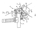
- la figure 1 est une représentation schématique en élévation latérale de l'appareil d'application conforme à l'invention,
- la figure 2 est une coupe partielle de l'appareil d'application selon la ligne II représentée sur la figure 1,
- la figure 3 est une représentation partielle en vue de dessous de l'appareil d'application selon la flèche F représentée à la figure 1,
- la figure 4 est une représentation perspective partielle en vue de dessus de l'appareil selon la flèche F' représentée à la figure 1.
- FIG. 1 is a diagrammatic representation in side elevation of the application apparatus according to the invention,
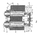
- FIG. 2 is a partial section of the application apparatus along the line II shown in FIG. 1,
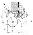
- FIG. 3 is a partial view from below of the application apparatus according to the arrow F represented in FIG. 1,
- FIG. 4 is a partial perspective view in plan view of the apparatus along arrow F 'shown in FIG.
Selon la figure 1, l'appareil d'application 1 d'une bandelette B de renforcement sur une surface de réception rotative (2) comprend un corps (5), la bandelette étant appliquée sur la surface de réception (2) dans une direction sensiblement perpendiculaire à l'axe de rotation de ladite surface tangentiellement à cette dernière. La surface de réception (2) tourne avec une vitesse circonférentielle contrôlée qu'on désignera par V2.According to FIG. 1, the
Dans ce qui suit, on désignera par « direction de progression de la bandelette », la direction sensiblement perpendiculaire à l'axe de rotation de la surface de réception (2).In what follows, the term "direction of progression of the strip", the direction substantially perpendicular to the axis of rotation of the receiving surface (2).
Le corps (5) porte des moyens de délivrance (10) de la bandelette, des moyens de déplacement transversal (20, 30) de la bandelette et enfin des moyens de pose (40) de cette bandelette sur la surface de réception (2). Ces différents organes agissent successivement pour réaliser l'application de la bandelette sur la surface de réception (2) avec les ondulations souhaitées de la bandelette et donc des fils ou des câblés contenus dans la bandelette.The body (5) carries means (10) for dispensing the strip, transverse displacement means (20, 30) for the strip and finally laying means (40) for this strip on the receiving surface (2). . These different organs act successively to achieve the application of the strip on the receiving surface (2) with the desired undulations of the strip and thus son or cords contained in the strip.
Comme on le voit sur la figure 4, les moyens (10) de délivrance comprennent au moins une poulie (12) d'arrivée de la bandelette, alimentée par un rouleau d'approvisionnement non représenté. L'axe de rotation de la poulie (12) est ici parallèle à celui de la surface de réception 2, ce qui permet au rouleau d'approvisionner aisément un cabestan (11) dont l'axe XX' est perpendiculaire à celui du rouleau (12).As seen in Figure 4, the means (10) for delivery comprise at least one pulley (12) of arrival of the strip, fed by a supply roller not shown. The axis of rotation of the pulley (12) is here parallel to that of the
En sortie de la poulie (12), la bandelette est orientée tangentiellement par rapport à la surface de réception (2) mais son passage sur le cabestan (11) entraîne un pivotement à 90° de la bandelette autour de son axe longitudinal. En sortie du cabestan (11), le plan de la nappe de fils ou de câblés constituant la bandelette est orienté perpendiculairement à l'axe de rotation de la surface de réception. Les fils ou les câblés de la bandelette ont donc tous la même position transversale par rapport à la surface de réception, la direction de chaque câblé correspondant à la direction de progression de la bandelette pour alimenter les moyens de déplacement transversal (20, 30) de la bandelette.At the output of the pulley (12), the strip is oriented tangentially with respect to the receiving surface (2) but its passage on the capstan (11) causes a 90 ° pivoting of the strip around its longitudinal axis. At the outlet of the capstan (11), the plane of the sheet of son or cords constituting the strip is oriented perpendicularly to the axis of rotation of the receiving surface. The son or cords of the strip therefore all have the same position transverse to the receiving surface, the direction of each cord corresponding to the direction of progression of the strip to feed the transverse displacement means (20, 30) of the strip. the strip.
Ainsi en sortie du cabestan, vu en élévation, tout se passe comme s'il n'y avait qu'un câblé à onduler.Thus at the output of the capstan, seen in elevation, everything happens as if there was only one cable to wave.
Le cabestan (11) est motorisé à l'aide d'un moteur (13), par l'intermédiaire d'une courroie de transmission (14) avec une vitesse circonférentielle que l'on notera V1. La maîtrise de la vitesse V1, en synchronisme avec la vitesse circonférentielle V2 de la surface de réception (2), permet de déterminer la quantité de bandelette délivrée sur la surface rotative (2) par tour de celle-ci.The capstan (11) is motorized by means of a motor (13), via a transmission belt (14) with a circumferential speed that will be noted V1. Controlling the speed V1, in synchronism with the circumferential speed V2 of the receiving surface (2), makes it possible to determine the quantity of strip delivered on the rotary surface (2) per turn thereof.
Les moyens de déplacement (20, 30) sont représentés plus particulièrement sur les figures 2 et 3 et comprennent une tête de guidage (20) coopérant avec les moyens (30) portés dans le corps (5).The displacement means (20, 30) are shown more particularly in Figures 2 and 3 and comprise a guide head (20) cooperating with the means (30) carried in the body (5).
La tête de guidage (20) comprend une bielle (21), perpendiculaire à l'axe XX' de rotation du cabestan (11), qui porté sur sa face (210) orientée vers l'extérieur de l'appareil d'application (1), deux galets de guidage (22 et 23) d'axes perpendiculaires à ladite bielle (21) et montés libres en rotation par rapport à cette dernière. La bandelette étant orientée parallèlement aux axes des galets, la présence de deux paires de galets tels que représentés sur la figure 3, est avantageuse pour améliorer le guidage de la bandelette.The guide head (20) comprises a connecting rod (21), perpendicular to the axis XX 'of rotation of the capstan (11), which bears on its face (210) oriented towards the outside of the application apparatus ( 1), two guide rollers (22 and 23) with axes perpendicular to said link (21) and mounted free to rotate relative thereto. The strip being oriented parallel to the axes of the rollers, the presence of two pairs of rollers as shown in Figure 3, is advantageous for improving the guidance of the strip.
Afin de faciliter le guidage de la bandelette de renforcement et de l'accompagner dans son déplacement transversal, on peut envisager que les galets de guidage de chaque paire (22 et 23) soient décalés dans sens de progression de la bandelette tout en étant tangents à la droite ayant la direction de progression de la bandelette et passant par le centre de la bielle (21). On peut également disposer les deux galets sans décalage entre eux tels qu'ils sont représentés sur les figures 2, 3 et 4.In order to facilitate the guiding of the reinforcing strip and to accompany it in its transverse displacement, it is conceivable for the guide rollers of each pair (22 and 23) to be offset in the direction of progression of the strip while being tangent to the straight line having the direction of progression of the strip and passing through the center of the connecting rod (21). It is also possible to arrange the two rollers without shifting between them as shown in FIGS. 2, 3 and 4.
Des arbres (24 et 25) d'axes parallèles entre eux sont montés à rotation libre dans les extrémités (211 et 212) de la bielle (21) par l'intermédiaire de roulements à billes (26), les axes des arbres (24 et 25) étant perpendiculaires à ladite bielle (21).Shafts (24 and 25) having parallel axes are freely rotatably mounted in the ends (211 and 212) of the connecting rod (21) by means of ball bearings (26) and the shafts (24). and 25) being perpendicular to said connecting rod (21).
Ces arbres (24 et 25) portent, en sortie de la bielle (21) située vers la face intérieure de la bielle (21) par rapport à l'appareil d'application, respectivement une chape (241, 251).These shafts (24 and 25) bear, at the outlet of the connecting rod (21) located towards the inner face of the connecting rod (21) relative to the application apparatus, respectively a yoke (241, 251).
Les moyens de déplacement (30) comprennent deux arbres (31 et 32) parallèles entre eux et perpendiculaires à la direction de progression de la bandelette, tournant dans des roulements à billes (33) portés par le corps (5) et motorisé à l'aide d'un moteur commun (non représenté) relié respectivement à une poulie d'entraînement (36, 37) pour chaque arbre par une même courroie de transmission (35).The displacement means (30) comprise two shafts (31 and 32) parallel to each other and perpendicular to the direction of progression of the strip, rotating in ball bearings (33) carried by the body (5) and motorized to the using a common motor (not shown) respectively connected to a drive pulley (36, 37) for each shaft by the same transmission belt (35).
Les arbres (31 et 32) se prolongent en sortie du corps (5) disposés vers la tête de guidage (20) par respectivement une chape (311, 321), ces chapes étant reliées respectivement aux chapes (241 et 251) par des biellettes (27 et 28) parallèles entre elles, assurant la transmission de la motorisation aux arbres (24 et 25).The shafts (31 and 32) extend at the outlet of the body (5) arranged towards the guide head (20) respectively by a yoke (311, 321), these yokes being respectively connected to the yokes (241 and 251) by connecting rods. (27 and 28) parallel to each other, ensuring transmission of the motorization to the shafts (24 and 25).
On désignera par Ω3 la vitesse de rotation des arbres (31, 32, 24 et 25).The speed of rotation of the shafts (31, 32, 24 and 25) will be referred to as Ω3.
La rotation des arbres (31 et 32) permet, avec le passage de la bandelette, de réaliser l'alternance de positionnement des biellettes (27 et 28). En effet, le pivotement des biellettes (27 et 28) autour de leur axe fixé sur les chapes (311 et 321) commande le décentrage de la bielle (21) par rapport aux arbres (31 et 32). Ainsi le centre de la bielle (21) décrit au cours de cette rotation, en projection sur un plan perpendiculaire à l'axe de rotation des arbres (31 et 32) un cercle.The rotation of the shafts (31 and 32) makes it possible, with the passage of the strip, to perform the alternating positioning of the links (27 and 28). Indeed, the pivoting rods (27 and 28) around their axis fixed on the yokes (311 and 321) controls the decentering of the connecting rod (21) relative to the shafts (31 and 32). Thus the center of the rod (21) described during this rotation, in projection on a plane perpendicular to the axis of rotation of the shafts (31 and 32) a circle.
Par ailleurs, le corps (5) porte sur sa face parallèle à la bielle (21), un électro-aimant (38) qui exerce une force de rappel sur la bielle (21).Furthermore, the body (5) carries on its face parallel to the connecting rod (21), an electromagnet (38) which exerts a restoring force on the connecting rod (21).
Les moyens de pose (40) de la bandelette sur la surface de réception (2) comprennent un galet de pose (41) tournant librement autour de son axe de rotation Y, dont la surface de révolution extérieure (410) est située contre la surface de réception (2) de sorte que la bandelette passe entre ladite surface de révolution et la surface de réception. Ce galet de pose (41) est situé à proximité des deux paires de galets de guidage (22 et 23) de sorte à accueillir la bandelette provenant de ces galets et de lui faire subir une rotation à 90° de sorte à ce que le plan de la nappe de fil constituant la bandelette soit orienté parallèlement à la surface de réception donc tangent à cette dernière.The laying means (40) of the strip on the receiving surface (2) comprise a laying roller (41) freely rotating about its axis of rotation Y, whose outer surface of revolution (410) is located against the surface receiving device (2) so that the strip passes between said surface of revolution and the receiving surface. This placing roller (41) is located near the two pairs of guide rollers (22 and 23) so as to receive the strip coming from these rollers and to rotate it by 90 ° so that the plane the strip of yarn constituting the strip is oriented parallel to the receiving surface and therefore tangential thereto.
Un bras (42) porte le galet de pose (41) à l'une de ses extrémités (420), l'autre extrémité (421) du bras étant fixé par l'intermédiaire d'un support (43) au corps (5), ledit support étant monté pivotant sur une articulation élastique (45) sur le corps (5) pour garantir la force d'applique de la bandelette sur la surface rotative (2).An arm (42) carries the delivery roller (41) at one of its ends (420), the other end (421) of the arm being fixed via a support (43) to the body (5). ), said support being pivotally mounted on an elastic hinge (45) on the body (5) to ensure the application force of the strip on the rotating surface (2).
On donnera dans ce qui suit succinctement quelques indications sur le fonctionnement de l'appareil d'application.In the following, a brief description will be given of the operation of the application apparatus.
Notons que la vitesse V2 de rotation de la surface de réception (2) étant déterminée, le réglage de la vitesse V1 de délivrance de la bandelette permet de fixer la quantité de bandelette délivrée par tour de la surface (2).Note that the speed V2 of rotation of the receiving surface (2) being determined, the setting of the delivery speed V1 of the strip makes it possible to fix the quantity of tape delivered per revolution of the surface (2).
En l'absence de bandelette, les arbres (31 et 32) étant en rotation, l'électro-aimant (38) maintient en position relevée la bielle (21) avec une position angulaire maximum des biellettes (27 et 28) par rapport aux chapes (311 et 321), et le centre de la bielle (21) décrira alors en projection sur un plan parallèle à la bielle (21); un cercle. Le diamètre de ce cercle correspondant à l'amplitude maximum possible de l'ondulationIn the absence of a strip, the shafts (31 and 32) being in rotation, the electromagnet (38) maintains in the raised position the connecting rod (21) with a maximum angular position of the links (27 and 28) with respect to screeds (311 and 321), and the center of the rod (21) will then describe in projection on a plane parallel to the connecting rod (21); a circle. The diameter of this circle corresponding to the maximum possible amplitude of the ripple
En présence d'une bandelette, un équilibre s'établit entre la force exercée par les rouleaux (22 et 23) sous l'action de l'électroaimant et qui aura pour effet de décentrer la bielle (21) et la force de rappel exercée par la bandelette qui va se tendre sous l'effet d'un déplacement transversal par rapport à la direction de progression.In the presence of a strip, a balance is established between the force exerted by the rollers (22 and 23) under the action of the electromagnet and which will have the effect of off-centering the connecting rod (21) and the restoring force exerted by the strip which will be stretched under the effect of a displacement transverse to the direction of progression.
Pour une vitesse V1=V2, l'action de la bielle (21) n'exerce aucun déplacement transversal de la bandelette, de sorte que les câblés sont posés de façon rectiligne.For a speed V1 = V2, the action of the connecting rod (21) exerts no transverse displacement of the strip, so that the cords are laid rectilinearly.
Lorsque la vitesse V1 de délivrance de la bandelette est supérieure à la vitesse V2 de la surface rotative, l'électroaimant va agir sur la bielle (21) par l'intermédiaire des biellettes (27 et 28) en exerçant une poussée transversale sur la bandelette jusqu'à ce qu'un équilibre se crée avec la force de rappel exercée par la bandelette ainsi mise en tension, la rotation des arbres (31 et 32) amenant l'alternance de position des biellettes (27, 28).When the delivery speed V1 of the strip is greater than the speed V2 of the rotating surface, the electromagnet will act on the connecting rod (21) via the rods (27 and 28) by exerting a transverse thrust on the strip until a balance is created with the restoring force exerted by the strip thus tensioned, the rotation of the shafts (31 and 32) causing the alternation of position of the rods (27, 28).
On remarquera que pour V1 supérieure à V2, la vitesse Ω3 de rotation des arbres (31 et 32) permet de déterminer l'alternance des biellettes (27 et 28) par tour de la surface de réception (2) et donc la période des ondulations réalisées par les câblés sur ladite surface. L'amplitude de ces ondulations est directement obtenue par la quantité de bandelette délivrée par tour de la surface de réception (2) puisque c'est cette quantité qui, en «poussant» la bielle (21), détermine l'angle d'inclinaison des biellettes (27 et 28).It will be noted that for V1 greater than V2, the speed Ω3 of rotation of the shafts (31 and 32) makes it possible to determine the alternation of the links (27 and 28) per revolution of the receiving surface (2) and therefore the period of the undulations. performed by the cords on said surface. The amplitude of these corrugations is directly obtained by the quantity of tape delivered per revolution of the receiving surface (2) since it is this quantity which, by "pushing" the connecting rod (21), determines the angle of inclination rods (27 and 28).
On comprendra également qu'il est important de tenir compte de la nature du câblé. En effet, plus le câblé est raide moins l'action de l'électroaimant est déterminante. On ajustera donc la force exercée par ce dernier selon qu'il s'agit d'un câblé métallique ou d'un câblé textile.It will also be understood that it is important to consider the nature of the cable. Indeed, the stiffer the cable is, the less the action of the electromagnet is decisive. We will adjust the force exerted by the latter depending on whether it is a metal cord or a textile cord.
De même, pour modifier aisément l'amplitude des ondulations des câblés et donc de la bandelette sur la surface de réception (2), afin comme on l'a vue au début du texte d'avoir des amplitudes différentes en continu selon la position radiale des câblés, il suffit de modifier la quantité de bandelette délivrée par tour de la surface (2) et donc la vitesse V1. L'amplitude des ondulations s'ajuste d'elle-même comme on l'a vu précédemment. Le système est donc très simple à adapter aux modifications des ondulations souhaitées.Similarly, to easily change the amplitude of the waviness of the cords and therefore the strip on the receiving surface (2), so as seen at the beginning of the text to have different amplitudes continuously depending on the radial position cabled, it is sufficient to change the amount of tape delivered per revolution of the surface (2) and therefore the speed V1. The amplitude of the undulations adjusts itself as we have seen previously. The system is therefore very simple to adapt to the changes of the desired undulations.
Claims (12)
- Apparatus (1) for applying a reinforcement strip to a receiving rotary surface (2), this reinforcement strip comprising a set of yarns or cords which are parallel to one another, generally coated in a rubber mix, arranged in the longitudinal direction and forming a continuous ply of a given width, comprising supply means (10), means (20, 30) of transverse displacement of the strip with respect to the direction in which the strip is laid on the receiving surface, and means (40) of laying, characterised in that the means of supplying the strip, whereof the yarns or cords are generally coated in a rubber mix, bring the latter to the means (20, 30) of transverse displacement with the plane of the ply of yarns or cords of the strip oriented substantially perpendicular to the axis of rotation of the receiving rotary surface (2), and in that the means (40) of laying the strip, which are located at the exit of the means (20, 30) of transverse displacement, perform a pivoting through 90° of the plane of the ply of yarns or cords of the said strip about an axis parallel to the direction in which the strip progresses, in order to arrange the plane of the ply of yarns or cords of the strip tangentially with respect to the receiving surface (2).
- Apparatus according to Claim 1, characterised in that the means (20, 30) of transverse displacement undergo an alternating movement.
- Apparatus according to Claim 2, for applying a reinforcement strip to a receiving rotary surface (2) at a circumferential speed V2, comprising a body (5) and comprising at least one rotary capstan (11) at a circumferential speed V1, characterised in that the amplitude of the alternating transverse displacement of the means (20, 30) of transverse displacement of the strip is controlled directly with respect to the speeds V1 and V2, this amplitude being capable of undergoing modification continuously as the strip is laid.
- Apparatus according to either of Claims 2 or 3, for applying a reinforcement strip, characterised in that the variation in amplitude of the alternating transverse displacement of the means (20, 30) of displacement is obtained by combining a rotary movement about an axis substantially perpendicular to the direction in which the strip progresses with a pivotal movement in a plane containing the axis of the said rotation, the amount of pivoting being determined by the ratio of the speeds V1 and V2.
- Apparatus according to any one of Claims 2 to 4, characterised in that the means (20, 30) of transverse displacement of the strip comprise first shafts (31, 32) capable of rotation perpendicular to the direction in which the strip progresses and carried by the body (5), and a head (20) for guiding the strip, which is mounted to pivot on the said first rotary shafts.
- Apparatus according to Claim 5, characterised in that the wavelength of the alternating transverse movements of the means of transverse displacement is proportional to the speed of rotation (Ω3) of the first rotary shafts (31, 32).
- Apparatus according to Claim 5 or 6, characterised in that the guide head (20) is connected to the first rotary shafts (31, 32) by connecting rods (27, 28), these connecting rods (27, 28) being themselves mounted on the guide head by way of second shafts (24, 25) whereof the axes are parallel to those of the first and which are mounted to rotate on the said guide head.
- Apparatus according to any one of Claims 5 to 7, characterised in that the guide head (20) comprises a connecting rod (21) carrying the second rotary shafts (24, 25).
- Apparatus according to any one of Claims 5 to 7, characterised in that the guide head (20) carries at least two rollers (22, 23) for guiding the strip whereof the axes are perpendicular to the direction in which the strip progresses and which are mounted to rotate freely on the guide head.
- Apparatus according to any one of Claims 5 to 9, characterised in that the body (5) carries an electromagnet (38) exerting a restoring force on the guide head.
- Apparatus according to any one of Claims 1 to 10, intended for manufacturing tyres.
- A process of applying a reinforcement strip to a receiving rotary surface, intended for manufacturing tyres, which comprises the following steps:- a strip whereof the plane of the ply of yarns or cords of the strip is oriented substantially perpendicular to the axis of rotation of the receiving surface is supplied;- the strip is displaced alternately, in a direction perpendicular to the plane of the ply of yarns or cords of the strip, in order to produce undulations on the latter;- the strip is pivoted through 90° about an axis parallel to the direction in which the strip progresses, and the latter is laid tangentially on the receiving rotary surface (2).
Applications Claiming Priority (3)
| Application Number | Priority Date | Filing Date | Title |
|---|---|---|---|
| FR0206871 | 2002-05-29 | ||
| FR0206871 | 2002-05-29 | ||
| PCT/EP2003/004723 WO2003099545A1 (en) | 2002-05-29 | 2003-05-06 | Device and method for applying a strip to a rotary surface |
Publications (2)
| Publication Number | Publication Date |
|---|---|
| EP1513673A1 EP1513673A1 (en) | 2005-03-16 |
| EP1513673B1 true EP1513673B1 (en) | 2006-04-26 |
Family
ID=29558964
Family Applications (1)
| Application Number | Title | Priority Date | Filing Date |
|---|---|---|---|
| EP03727440A Expired - Lifetime EP1513673B1 (en) | 2002-05-29 | 2003-05-06 | Device and method for applying a strip to a rotary surface |
Country Status (9)
| Country | Link |
|---|---|
| US (1) | US7201200B2 (en) |
| EP (1) | EP1513673B1 (en) |
| JP (1) | JP4309339B2 (en) |
| CN (1) | CN100441405C (en) |
| AT (1) | ATE324249T1 (en) |
| AU (1) | AU2003233240A1 (en) |
| BR (1) | BR0304886B1 (en) |
| DE (1) | DE60304861T2 (en) |
| WO (1) | WO2003099545A1 (en) |
Families Citing this family (29)
| Publication number | Priority date | Publication date | Assignee | Title |
|---|---|---|---|---|
| FR2882535B1 (en) * | 2005-02-28 | 2007-04-13 | Michelin Soc Tech | DEVICE AND METHOD FOR MANUFACTURING WAVE PATCHES |
| US8632653B2 (en) | 2005-05-03 | 2014-01-21 | The Boeing Company | Method of manufacturing curved composite structural elements |
| EP1945443B1 (en) * | 2005-11-11 | 2012-05-16 | PIRELLI TYRE S.p.A. | A plant for manufacturing tyres and manufacturing method related thereto |
| US7686053B2 (en) * | 2005-12-01 | 2010-03-30 | The Goodyear Tire & Rubber Company | Cord tensioning and feed mechanism for a tire cord applicator head |
| BRPI0520772B1 (en) * | 2005-12-23 | 2016-12-20 | Pirelli | method for manufacturing a tire and method and apparatus for manufacturing an annular anchor structure of a vehicle wheel tire |
| JP4866123B2 (en) * | 2006-03-27 | 2012-02-01 | 横浜ゴム株式会社 | Pneumatic tire manufacturing method |
| US8578994B2 (en) * | 2006-12-19 | 2013-11-12 | The Goodyear Tire & Rubber Company | Applicator head for tire cord construction |
| JP2009061717A (en) * | 2007-09-07 | 2009-03-26 | Bridgestone Corp | Manufacturing equipment of tire reinforcing band, and manufacturing process of tire reinforcing band |
| FR2921296B1 (en) * | 2007-09-20 | 2009-11-27 | Michelin Soc Tech | ROTARY POSITION ARM COMPRISING A MEANS FOR CALLING THE INBOOT WIRE |
| US9278484B2 (en) | 2008-04-17 | 2016-03-08 | The Boeing Company | Method and apparatus for producing contoured composite structures and structures produced thereby |
| US9090028B2 (en) | 2008-04-17 | 2015-07-28 | The Boeing Company | Method for producing contoured composite structures and structures produced thereby |
| US8932423B2 (en) | 2008-04-17 | 2015-01-13 | The Boeing Company | Method for producing contoured composite structures and structures produced thereby |
| US8349105B2 (en) | 2008-04-17 | 2013-01-08 | The Boeing Company | Curved composite frames and method of making the same |
| EP2283998A4 (en) * | 2008-06-04 | 2012-07-04 | Bridgestone Corp | Tire manufacturing method and apparatus |
| DE102010015199B9 (en) * | 2010-04-16 | 2013-08-01 | Compositence Gmbh | Fiber guiding device and apparatus for constructing a three-dimensional preform |
| DE102011100640A1 (en) | 2011-05-05 | 2012-11-08 | Compositence Gmbh | Method and apparatus for making fiber webs and component preforms from fibers |
| GB2492594B (en) * | 2011-07-08 | 2016-08-17 | Univ Bristol | Tow placement apparatus and methods |
| CN102529115B (en) * | 2011-12-31 | 2014-04-02 | 哈尔滨工业大学 | Automatic fiber laying variable-angle path planning method for non-developable curved surface part |
| DE102012007439A1 (en) | 2012-04-13 | 2013-10-17 | Compositence Gmbh | Laying head and apparatus and method for building a three-dimensional preform for a component made of a fiber composite material |
| EP2695810B1 (en) | 2012-08-09 | 2016-10-19 | Airbus Operations GmbH | Drive system for control surfaces of an aircraft |
| CN104903078B (en) | 2012-12-28 | 2018-08-07 | 科朋兹腾斯有限公司 | The method and apparatus for manufacturing three dimensional fibrous web and the component prefabricated component made of fiber with two steps |
| DE202014102032U1 (en) | 2014-04-30 | 2015-08-03 | Deutsches Zentrum für Luft- und Raumfahrt e.V. | Fiber laying head |
| NL2013314B1 (en) * | 2014-08-08 | 2016-09-21 | Vmi Holland Bv | Stretching device for an apex filler strip and apex handling system comprising the stretching device. |
| WO2016120922A1 (en) * | 2015-01-30 | 2016-08-04 | トクセン工業株式会社 | Method and apparatus for manufacturing rubber sheet incorporating steel cord |
| JP6514543B2 (en) * | 2015-03-26 | 2019-05-15 | トクセン工業株式会社 | Method and apparatus for manufacturing rubber sheet containing steel cord |
| CN108773097B (en) * | 2018-05-23 | 2023-07-21 | 联亚智能科技(苏州)有限公司 | Rubber strip cooling device and automatic rubber part winding unit |
| TWI756673B (en) * | 2020-04-30 | 2022-03-01 | 廣野精機股份有限公司 | Bottom thread swing rod linkage mechanism of belt loom |
| US20230311430A1 (en) | 2020-09-17 | 2023-10-05 | Icomat Limited | A tape laying head |
| CN113478880B (en) * | 2021-07-26 | 2023-06-23 | 江苏环柔轮胎科技有限公司 | A variable amplitude corrugated winding method for crown strips |
Family Cites Families (12)
| Publication number | Priority date | Publication date | Assignee | Title |
|---|---|---|---|---|
| US3523854A (en) * | 1966-09-26 | 1970-08-11 | Nrm Corp | Apparatus for applying strip tread on tire building drum |
| US3761341A (en) * | 1971-04-12 | 1973-09-25 | Deering Milliken Res Corp | Apparatus for guiding a strip to a support surface |
| US4600456A (en) * | 1984-08-02 | 1986-07-15 | Armstrong Rubber Company | Method and apparatus for forming woven endless tire reinforcing belts |
| US4874455A (en) * | 1987-01-29 | 1989-10-17 | The Armstrong Rubber Co. | Apparatus for forming endless tire reinforcing belts |
| US5192390A (en) * | 1987-11-13 | 1993-03-09 | Bridgestone/Firestone Inc. | Mandrel means |
| JP2532913B2 (en) * | 1988-03-30 | 1996-09-11 | 株式会社ブリヂストン | Method for manufacturing tire reinforcing member |
| JPH04173404A (en) * | 1990-11-06 | 1992-06-22 | Sumitomo Rubber Ind Ltd | Pneumatic tire |
| FR2729976A1 (en) * | 1995-02-01 | 1996-08-02 | Michelin & Cie | METHOD AND DEVICE FOR APPLYING A WIRE TO A SUPPORT |
| JPH10296873A (en) * | 1997-04-24 | 1998-11-10 | Yokohama Rubber Co Ltd:The | Method and device for molding belt layer of pneumatic tire |
| JP3322648B2 (en) * | 1999-03-03 | 2002-09-09 | 住友ゴム工業株式会社 | Rubber conveying device and rubber molding device using the same |
| FR2817251A1 (en) | 2000-11-28 | 2002-05-31 | Michelin Soc Tech | APPARATUS FOR APPLYING A CABLE TO A ROTATING SURFACE |
| JP2003071946A (en) * | 2001-09-06 | 2003-03-12 | Bridgestone Corp | Tire for two-wheeled vehicle and its manufacturing method |
-
2003
- 2003-05-06 AT AT03727440T patent/ATE324249T1/en not_active IP Right Cessation
- 2003-05-06 EP EP03727440A patent/EP1513673B1/en not_active Expired - Lifetime
- 2003-05-06 JP JP2004507053A patent/JP4309339B2/en not_active Expired - Fee Related
- 2003-05-06 BR BRPI0304886-1A patent/BR0304886B1/en not_active IP Right Cessation
- 2003-05-06 WO PCT/EP2003/004723 patent/WO2003099545A1/en not_active Ceased
- 2003-05-06 CN CNB038123010A patent/CN100441405C/en not_active Expired - Fee Related
- 2003-05-06 DE DE60304861T patent/DE60304861T2/en not_active Expired - Lifetime
- 2003-05-06 AU AU2003233240A patent/AU2003233240A1/en not_active Abandoned
-
2004
- 2004-11-29 US US10/997,862 patent/US7201200B2/en not_active Expired - Fee Related
Also Published As
| Publication number | Publication date |
|---|---|
| CN1655923A (en) | 2005-08-17 |
| JP2005527408A (en) | 2005-09-15 |
| CN100441405C (en) | 2008-12-10 |
| US7201200B2 (en) | 2007-04-10 |
| US20050139324A1 (en) | 2005-06-30 |
| WO2003099545A1 (en) | 2003-12-04 |
| DE60304861D1 (en) | 2006-06-01 |
| EP1513673A1 (en) | 2005-03-16 |
| BR0304886B1 (en) | 2013-02-19 |
| DE60304861T2 (en) | 2006-11-16 |
| ATE324249T1 (en) | 2006-05-15 |
| AU2003233240A1 (en) | 2003-12-12 |
| BR0304886A (en) | 2004-07-20 |
| JP4309339B2 (en) | 2009-08-05 |
Similar Documents
| Publication | Publication Date | Title |
|---|---|---|
| EP1513673B1 (en) | Device and method for applying a strip to a rotary surface | |
| EP0582215B1 (en) | Method for manufacturing tires and apparatus for manufacturing a crown reinforcement for tires | |
| EP0248301B1 (en) | Method and apparatus for making a reinforcement for a tyre | |
| EP0148061A1 (en) | Apparatus for the continuous manufacture of a tubular structure of helically wound interlocking strip material | |
| EP0519294B1 (en) | Method for the production of a tyre and machine for implementing the method | |
| EP1208963B1 (en) | Apparatus for applying a cord on a rotating surface and method of using this apparatus | |
| FR2999466A1 (en) | FIBER PLACEMENT MACHINE COMPRISING A ROLLER WITH SWIVEL RINGS | |
| EP1147864B1 (en) | High speed cutting device for cutting reinforcing elements for tyres | |
| EP0724949B1 (en) | Process and apparatus for applying a filament to a support | |
| EP0318791B1 (en) | Apparatus and method for applying cords onto a support | |
| FR2535298A1 (en) | DEVICE FOR CONNECTING EACH OTHER TWO COILS OF BAND MATERIAL | |
| EP1426170B1 (en) | Apparatus having multiple application arms for the manufacture of a reinforcing element for tyres | |
| EP1590169B1 (en) | Apparatus for producing a tire reinforcement provided with a device for guiding the reinforcing wire and method of manufacturing a tire reinforcement using such an apparatus. | |
| FR2650776A1 (en) | METHOD AND DEVICE FOR INTERIOR COATING OF CONTAINERS | |
| CH426241A (en) | Process for manufacturing tires, tire manufactured according to this process and apparatus for implementing this process | |
| CA2053937A1 (en) | Process and device for applying wires on a substrate using a drum with rows of fixed and mobile teeth, layer obtained by this process and article using that layer (tire) | |
| EP3237230B1 (en) | Device for depositing a crimped wire on a receiving surface | |
| EP1147865A2 (en) | Apparatus for cutting a wire | |
| FR2473027A1 (en) | Continuous sheet metal strip cutter - has winding drum feeding cutters passing to separating rolls with sheet tensioner(SE 20.7.81) | |
| EP1824666B1 (en) | Appliance for producing a reinforcement for a pneumatic tyre | |
| EP3237191A1 (en) | Device and method for depositing a crimped wire on a receiving surface | |
| FR2580675A1 (en) | Process for producing a yarn by projecting fibres onto a perforated element | |
| BE865364A (en) | TRANSVERSAL DISPLACEMENT MECHANISM FOR WINDING GLASS FIBERS |
Legal Events
| Date | Code | Title | Description |
|---|---|---|---|
| PUAI | Public reference made under article 153(3) epc to a published international application that has entered the european phase |
Free format text: ORIGINAL CODE: 0009012 |
|
| 17P | Request for examination filed |
Effective date: 20041229 |
|
| AK | Designated contracting states |
Kind code of ref document: A1 Designated state(s): AT BE BG CH CY CZ DE DK EE ES FI FR GB GR HU IE IT LI LU MC NL PT RO SE SI SK TR |
|
| AX | Request for extension of the european patent |
Extension state: AL LT LV MK |
|
| DAX | Request for extension of the european patent (deleted) | ||
| GRAP | Despatch of communication of intention to grant a patent |
Free format text: ORIGINAL CODE: EPIDOSNIGR1 |
|
| GRAS | Grant fee paid |
Free format text: ORIGINAL CODE: EPIDOSNIGR3 |
|
| GRAA | (expected) grant |
Free format text: ORIGINAL CODE: 0009210 |
|
| AK | Designated contracting states |
Kind code of ref document: B1 Designated state(s): AT BE BG CH CY CZ DE DK EE ES FI FR GB GR HU IE IT LI LU MC NL PT RO SE SI SK TR |
|
| PG25 | Lapsed in a contracting state [announced via postgrant information from national office to epo] |
Ref country code: AT Free format text: LAPSE BECAUSE OF FAILURE TO SUBMIT A TRANSLATION OF THE DESCRIPTION OR TO PAY THE FEE WITHIN THE PRESCRIBED TIME-LIMIT Effective date: 20060426 Ref country code: IE Free format text: LAPSE BECAUSE OF FAILURE TO SUBMIT A TRANSLATION OF THE DESCRIPTION OR TO PAY THE FEE WITHIN THE PRESCRIBED TIME-LIMIT Effective date: 20060426 Ref country code: CZ Free format text: LAPSE BECAUSE OF FAILURE TO SUBMIT A TRANSLATION OF THE DESCRIPTION OR TO PAY THE FEE WITHIN THE PRESCRIBED TIME-LIMIT Effective date: 20060426 Ref country code: FI Free format text: LAPSE BECAUSE OF FAILURE TO SUBMIT A TRANSLATION OF THE DESCRIPTION OR TO PAY THE FEE WITHIN THE PRESCRIBED TIME-LIMIT Effective date: 20060426 Ref country code: SK Free format text: LAPSE BECAUSE OF FAILURE TO SUBMIT A TRANSLATION OF THE DESCRIPTION OR TO PAY THE FEE WITHIN THE PRESCRIBED TIME-LIMIT Effective date: 20060426 Ref country code: SI Free format text: LAPSE BECAUSE OF FAILURE TO SUBMIT A TRANSLATION OF THE DESCRIPTION OR TO PAY THE FEE WITHIN THE PRESCRIBED TIME-LIMIT Effective date: 20060426 Ref country code: RO Free format text: LAPSE BECAUSE OF FAILURE TO SUBMIT A TRANSLATION OF THE DESCRIPTION OR TO PAY THE FEE WITHIN THE PRESCRIBED TIME-LIMIT Effective date: 20060426 Ref country code: NL Free format text: LAPSE BECAUSE OF FAILURE TO SUBMIT A TRANSLATION OF THE DESCRIPTION OR TO PAY THE FEE WITHIN THE PRESCRIBED TIME-LIMIT Effective date: 20060426 |
|
| REG | Reference to a national code |
Ref country code: GB Ref legal event code: FG4D Free format text: NOT ENGLISH |
|
| GBT | Gb: translation of ep patent filed (gb section 77(6)(a)/1977) |
Effective date: 20060426 |
|
| PG25 | Lapsed in a contracting state [announced via postgrant information from national office to epo] |
Ref country code: MC Free format text: LAPSE BECAUSE OF NON-PAYMENT OF DUE FEES Effective date: 20060531 Ref country code: BE Free format text: LAPSE BECAUSE OF NON-PAYMENT OF DUE FEES Effective date: 20060531 |
|
| REG | Reference to a national code |
Ref country code: IE Ref legal event code: FG4D Free format text: LANGUAGE OF EP DOCUMENT: FRENCH |
|
| REF | Corresponds to: |
Ref document number: 60304861 Country of ref document: DE Date of ref document: 20060601 Kind code of ref document: P |
|
| PG25 | Lapsed in a contracting state [announced via postgrant information from national office to epo] |
Ref country code: SE Free format text: LAPSE BECAUSE OF FAILURE TO SUBMIT A TRANSLATION OF THE DESCRIPTION OR TO PAY THE FEE WITHIN THE PRESCRIBED TIME-LIMIT Effective date: 20060726 Ref country code: DK Free format text: LAPSE BECAUSE OF FAILURE TO SUBMIT A TRANSLATION OF THE DESCRIPTION OR TO PAY THE FEE WITHIN THE PRESCRIBED TIME-LIMIT Effective date: 20060726 |
|
| PG25 | Lapsed in a contracting state [announced via postgrant information from national office to epo] |
Ref country code: ES Free format text: LAPSE BECAUSE OF FAILURE TO SUBMIT A TRANSLATION OF THE DESCRIPTION OR TO PAY THE FEE WITHIN THE PRESCRIBED TIME-LIMIT Effective date: 20060806 |
|
| PG25 | Lapsed in a contracting state [announced via postgrant information from national office to epo] |
Ref country code: PT Free format text: LAPSE BECAUSE OF FAILURE TO SUBMIT A TRANSLATION OF THE DESCRIPTION OR TO PAY THE FEE WITHIN THE PRESCRIBED TIME-LIMIT Effective date: 20060926 |
|
| NLV1 | Nl: lapsed or annulled due to failure to fulfill the requirements of art. 29p and 29m of the patents act | ||
| REG | Reference to a national code |
Ref country code: IE Ref legal event code: FD4D |
|
| PLBE | No opposition filed within time limit |
Free format text: ORIGINAL CODE: 0009261 |
|
| STAA | Information on the status of an ep patent application or granted ep patent |
Free format text: STATUS: NO OPPOSITION FILED WITHIN TIME LIMIT |
|
| 26N | No opposition filed |
Effective date: 20070129 |
|
| BERE | Be: lapsed |
Owner name: SOC. DE TECHNOLOGIE MICHELIN Effective date: 20060531 Owner name: MICHELIN RECHERCHE ET TECHNIQUE S.A. Effective date: 20060531 |
|
| REG | Reference to a national code |
Ref country code: CH Ref legal event code: PL |
|
| PG25 | Lapsed in a contracting state [announced via postgrant information from national office to epo] |
Ref country code: CH Free format text: LAPSE BECAUSE OF NON-PAYMENT OF DUE FEES Effective date: 20070531 Ref country code: LI Free format text: LAPSE BECAUSE OF NON-PAYMENT OF DUE FEES Effective date: 20070531 |
|
| PG25 | Lapsed in a contracting state [announced via postgrant information from national office to epo] |
Ref country code: GR Free format text: LAPSE BECAUSE OF FAILURE TO SUBMIT A TRANSLATION OF THE DESCRIPTION OR TO PAY THE FEE WITHIN THE PRESCRIBED TIME-LIMIT Effective date: 20060727 |
|
| PG25 | Lapsed in a contracting state [announced via postgrant information from national office to epo] |
Ref country code: BG Free format text: LAPSE BECAUSE OF FAILURE TO SUBMIT A TRANSLATION OF THE DESCRIPTION OR TO PAY THE FEE WITHIN THE PRESCRIBED TIME-LIMIT Effective date: 20060726 Ref country code: EE Free format text: LAPSE BECAUSE OF FAILURE TO SUBMIT A TRANSLATION OF THE DESCRIPTION OR TO PAY THE FEE WITHIN THE PRESCRIBED TIME-LIMIT Effective date: 20060426 |
|
| PG25 | Lapsed in a contracting state [announced via postgrant information from national office to epo] |
Ref country code: TR Free format text: LAPSE BECAUSE OF FAILURE TO SUBMIT A TRANSLATION OF THE DESCRIPTION OR TO PAY THE FEE WITHIN THE PRESCRIBED TIME-LIMIT Effective date: 20060426 Ref country code: HU Free format text: LAPSE BECAUSE OF FAILURE TO SUBMIT A TRANSLATION OF THE DESCRIPTION OR TO PAY THE FEE WITHIN THE PRESCRIBED TIME-LIMIT Effective date: 20061027 |
|
| PG25 | Lapsed in a contracting state [announced via postgrant information from national office to epo] |
Ref country code: CY Free format text: LAPSE BECAUSE OF FAILURE TO SUBMIT A TRANSLATION OF THE DESCRIPTION OR TO PAY THE FEE WITHIN THE PRESCRIBED TIME-LIMIT Effective date: 20060426 |
|
| PGFP | Annual fee paid to national office [announced via postgrant information from national office to epo] |
Ref country code: LU Payment date: 20090602 Year of fee payment: 7 |
|
| PGFP | Annual fee paid to national office [announced via postgrant information from national office to epo] |
Ref country code: GB Payment date: 20090522 Year of fee payment: 7 |
|
| GBPC | Gb: european patent ceased through non-payment of renewal fee |
Effective date: 20100506 |
|
| PG25 | Lapsed in a contracting state [announced via postgrant information from national office to epo] |
Ref country code: GB Free format text: LAPSE BECAUSE OF NON-PAYMENT OF DUE FEES Effective date: 20100506 |
|
| PG25 | Lapsed in a contracting state [announced via postgrant information from national office to epo] |
Ref country code: IT Free format text: LAPSE BECAUSE OF NON-PAYMENT OF DUE FEES Effective date: 20110506 |
|
| PG25 | Lapsed in a contracting state [announced via postgrant information from national office to epo] |
Ref country code: LU Free format text: LAPSE BECAUSE OF NON-PAYMENT OF DUE FEES Effective date: 20100506 |
|
| PGRI | Patent reinstated in contracting state [announced from national office to epo] |
Ref country code: IT Effective date: 20130107 |
|
| PGFP | Annual fee paid to national office [announced via postgrant information from national office to epo] |
Ref country code: IT Payment date: 20130528 Year of fee payment: 11 |
|
| PG25 | Lapsed in a contracting state [announced via postgrant information from national office to epo] |
Ref country code: IT Free format text: LAPSE BECAUSE OF NON-PAYMENT OF DUE FEES Effective date: 20140506 |
|
| REG | Reference to a national code |
Ref country code: FR Ref legal event code: PLFP Year of fee payment: 14 |
|
| REG | Reference to a national code |
Ref country code: FR Ref legal event code: PLFP Year of fee payment: 15 |
|
| REG | Reference to a national code |
Ref country code: FR Ref legal event code: PLFP Year of fee payment: 16 |
|
| PGFP | Annual fee paid to national office [announced via postgrant information from national office to epo] |
Ref country code: DE Payment date: 20180522 Year of fee payment: 16 |
|
| PGFP | Annual fee paid to national office [announced via postgrant information from national office to epo] |
Ref country code: FR Payment date: 20180522 Year of fee payment: 16 |
|
| REG | Reference to a national code |
Ref country code: DE Ref legal event code: R119 Ref document number: 60304861 Country of ref document: DE |
|
| PG25 | Lapsed in a contracting state [announced via postgrant information from national office to epo] |
Ref country code: DE Free format text: LAPSE BECAUSE OF NON-PAYMENT OF DUE FEES Effective date: 20191203 |
|
| PG25 | Lapsed in a contracting state [announced via postgrant information from national office to epo] |
Ref country code: FR Free format text: LAPSE BECAUSE OF NON-PAYMENT OF DUE FEES Effective date: 20190531 |