US4941378A - Method and apparatus for rapid repetitive cutting - Google Patents
Method and apparatus for rapid repetitive cutting Download PDFInfo
- Publication number
- US4941378A US4941378A US07/261,307 US26130788A US4941378A US 4941378 A US4941378 A US 4941378A US 26130788 A US26130788 A US 26130788A US 4941378 A US4941378 A US 4941378A
- Authority
- US
- United States
- Prior art keywords
- knife
- tube
- cutting
- axis
- cutting site
- Prior art date
- Legal status (The legal status is an assumption and is not a legal conclusion. Google has not performed a legal analysis and makes no representation as to the accuracy of the status listed.)
- Expired - Lifetime
Links
Images

Classifications
-
- B—PERFORMING OPERATIONS; TRANSPORTING
- B23—MACHINE TOOLS; METAL-WORKING NOT OTHERWISE PROVIDED FOR
- B23D—PLANING; SLOTTING; SHEARING; BROACHING; SAWING; FILING; SCRAPING; LIKE OPERATIONS FOR WORKING METAL BY REMOVING MATERIAL, NOT OTHERWISE PROVIDED FOR
- B23D21/00—Machines or devices for shearing or cutting tubes
-
- B—PERFORMING OPERATIONS; TRANSPORTING
- B26—HAND CUTTING TOOLS; CUTTING; SEVERING
- B26D—CUTTING; DETAILS COMMON TO MACHINES FOR PERFORATING, PUNCHING, CUTTING-OUT, STAMPING-OUT OR SEVERING
- B26D1/00—Cutting through work characterised by the nature or movement of the cutting member or particular materials not otherwise provided for; Apparatus or machines therefor; Cutting members therefor
- B26D1/01—Cutting through work characterised by the nature or movement of the cutting member or particular materials not otherwise provided for; Apparatus or machines therefor; Cutting members therefor involving a cutting member which does not travel with the work
- B26D1/12—Cutting through work characterised by the nature or movement of the cutting member or particular materials not otherwise provided for; Apparatus or machines therefor; Cutting members therefor involving a cutting member which does not travel with the work having a cutting member moving about an axis
- B26D1/25—Cutting through work characterised by the nature or movement of the cutting member or particular materials not otherwise provided for; Apparatus or machines therefor; Cutting members therefor involving a cutting member which does not travel with the work having a cutting member moving about an axis with a non-circular cutting member
- B26D1/26—Cutting through work characterised by the nature or movement of the cutting member or particular materials not otherwise provided for; Apparatus or machines therefor; Cutting members therefor involving a cutting member which does not travel with the work having a cutting member moving about an axis with a non-circular cutting member moving about an axis substantially perpendicular to the line of cut
- B26D1/28—Cutting through work characterised by the nature or movement of the cutting member or particular materials not otherwise provided for; Apparatus or machines therefor; Cutting members therefor involving a cutting member which does not travel with the work having a cutting member moving about an axis with a non-circular cutting member moving about an axis substantially perpendicular to the line of cut and rotating continuously in one direction during cutting
- B26D1/29—Cutting through work characterised by the nature or movement of the cutting member or particular materials not otherwise provided for; Apparatus or machines therefor; Cutting members therefor involving a cutting member which does not travel with the work having a cutting member moving about an axis with a non-circular cutting member moving about an axis substantially perpendicular to the line of cut and rotating continuously in one direction during cutting with cutting member mounted in the plane of a rotating disc, e.g. for slicing beans
-
- B—PERFORMING OPERATIONS; TRANSPORTING
- B26—HAND CUTTING TOOLS; CUTTING; SEVERING
- B26D—CUTTING; DETAILS COMMON TO MACHINES FOR PERFORATING, PUNCHING, CUTTING-OUT, STAMPING-OUT OR SEVERING
- B26D3/00—Cutting work characterised by the nature of the cut made; Apparatus therefor
- B26D3/16—Cutting rods or tubes transversely
- B26D3/167—Cutting tubes having a non-circular cross-section
- B26D3/168—Cutting tubes having a non-circular cross-section flattened tubes
-
- Y—GENERAL TAGGING OF NEW TECHNOLOGICAL DEVELOPMENTS; GENERAL TAGGING OF CROSS-SECTIONAL TECHNOLOGIES SPANNING OVER SEVERAL SECTIONS OF THE IPC; TECHNICAL SUBJECTS COVERED BY FORMER USPC CROSS-REFERENCE ART COLLECTIONS [XRACs] AND DIGESTS
- Y10—TECHNICAL SUBJECTS COVERED BY FORMER USPC
- Y10T—TECHNICAL SUBJECTS COVERED BY FORMER US CLASSIFICATION
- Y10T83/00—Cutting
- Y10T83/444—Tool engages work during dwell of intermittent workfeed
- Y10T83/4594—Dwell caused by clamping or blocking work during continuous operation of feed means
-
- Y—GENERAL TAGGING OF NEW TECHNOLOGICAL DEVELOPMENTS; GENERAL TAGGING OF CROSS-SECTIONAL TECHNOLOGIES SPANNING OVER SEVERAL SECTIONS OF THE IPC; TECHNICAL SUBJECTS COVERED BY FORMER USPC CROSS-REFERENCE ART COLLECTIONS [XRACs] AND DIGESTS
- Y10—TECHNICAL SUBJECTS COVERED BY FORMER USPC
- Y10T—TECHNICAL SUBJECTS COVERED BY FORMER US CLASSIFICATION
- Y10T83/00—Cutting
- Y10T83/485—Cutter with timed stroke relative to moving work
- Y10T83/492—With means to vary timing of tool feed
Definitions
- This invention relates to a rotating cutting knife and a cutting method and more particularly to a cutting knife and method especially adapted to cutting repetitively at a high rate.
- a continuous tube is emitted from a tube mill at a high speed and the tube is cut into desired lengths as needed for specified usage or for convenient storage or shipping.
- the conventional cutting method uses a guillotine type cutter which chops the tube in a downward motion and is then retracted by an upward motion.
- the knife carried on a shuttle, moves in the direction of tube advance during cutting and retracting. Then the shuttle must return the knife to a start position for the next cut.
- the alternating motion in two directions, forward and back motion of the shuttle and knife as well as up and down motion of the knife is inefficient from the standpoint of overcoming inertia when reversing the movements.
- the inertia is substantial due to the considerable mass of the cutting mechanism.
- the time required for such cutting procedure places a limit on the production rate of the tubing.
- the method of the invention is carried out by continuously rotating a knife about a knife rotation axis, moving the knife to the cutting site for one knife rotation for cutting an element and moving the knife away from the cutting site for a plurality of knife rotations by traversing the axis through a path at a rate requiring a plurality of knife rotations for each traverse of the path.
- the invention is also carried out by a cutting mechanism comprising; rotary support means for rotation about a first axis, a knife mounted on the support for rotation about a second axis spaced from the first axis, a cutting site adjacent the support means and in the path of the knife for a given rotary position of the rotary support means, and motor means for driving the rotary support and the knife about respective axes, whereby the knife moves in a compound arcuate path which intersects the cutting site.
- FIG. 1 is a schematic side view of a cutter mechanism according to the invention
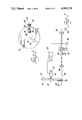
- FIG. 2 is a schematic top view of the cutter of FIG. 1 and the tube feed and control mechanism
- FIG. 3 is a partly broken away isometric view of the cutter mechanism of FIG. 1.
- the method and apparatus of cutting an element by a rotating blade is especially designed for the cutting of tubing into prescribed lengths but it will be apparent that it also applies to the cutting of other elements.
- the cutter wheel 10 comprises a rotatable support 12 driven by a motor 14 for rotation about an axis 16.
- a knife 18 is pivotably mounted for rotation about an axis 20 and is rotatably driven by means to be described.
- the knife 18 is elongate and has a blade 22 at one end and a counterweight 24 at the other end.
- the blade 22 extends beyond the periphery of the support 12 when the knife is angularly disposed with the blade outward but the counterweight does not ever extend beyond the support.
- the tube 26 to be cut is shown in section in FIG. 1 and is a flat thin walled tube of metal such as aluminum which is readily cut by a single stroke of a rapidly moving blade.
- the blade is a well known structure called a Vogal knife which has a central cusp 28 for piercing the top of the tube and a curved concave blade portion 30 on either side of the cusp 28 for slicing through the side walls of the tube.
- the knife 18 is arranged to rotate about its axis 20 several times for each rotation of the support 12. An intermediate knife position is shown at 18'. The knife is in position to intersect the path of the tube 26 only once during each rotation of the support 12 and the successive knife rotations are idle, allowing time for the tube to advance to the next desired cut-off point.
- the tube preferably originates from a tube mill, not shown, and advances at a constant preset speed.
- the tube 26 is advanced by drive rollers 32, operated by a motor 34 and is guided toward the cutter station by idler rollers 36.
- the cutter station comprises the vicinity of the cutter wheel 10 and has two sets of die blocks 38 spaced on opposite sides of the path of the blade 22 for positioning and supporting the tube 26 during the cut.
- a pair of pinch rollers 40 engage the tube midway between the drive rollers 32 and the idler rollers 36.
- the pinch rollers 40 are mounted on a slide 42 or the like for movement in a direction transverse to the tube advance movement.
- the slide 42 carries a cam follower 44 which is driven by a cam 46.
- the cam 46 in turn is rotated by a servomotor 48 controlled by a control circuit 50.
- the control circuit 50 also controls the motor 14 and has an input from a position encoder 52 on the motor 14 which reveals the cutter wheel position to the control circuit.
- the tube mill can be expected to produce tubing at a rate of 600 feet per minute. Assuming the tube is to be cut at 2 foot lengths, the wheel speed will be 300 rpm. For a distance of 10 inches between the two axes of rotation and a knife length of 6 inches from its axis to the cutting edge, the linear velocity component due to the wheel rotation will be 500 inches per second. If the knife rotates at 3000 rpm, that adds a velocity component of 1800 ips. If the tube height is 13/8 inch and the blade height is 2 inches, the knife will be in contact with the tube for a cutting interval of 0.00143 seconds. During that time the tube advance would be 0.172 inch. For a separation of six feet between the rollers 32 and 36, a bowing displacement of about 2.5 inch is adequate to produce the increased path length.
- a planetary gear set is used to rotate the knife 18 about its own pivot axis 20 and to revolve the knife about the axis 16 of the support 12.
- the support 12 is the planetary carrier for the gear set.
- a fixed housing 55 has a first cylindrical portion 56 which encloses the cutter wheel 10 and a second cylindrical portion 57 of greater diameter than the first which has room for knife rotation and has ports 58 which permit the tube 26 to pass through the cutting station.
- a stationary internal ring gear 60 is secured to the housing by a hollow hub 62.
- the carrier or support 12 is hollow and contains all the gears of the planetary gear set.
- the carrier has a generally cylindrical shape and has a hub aperture 61 which is rotatably mounted by bearings 64 on the outer surface of the hub 62.
- the carrier has an axle 63 extending opposite the bearings 64 which is journaled within a tubular boss 65 in the housing 55.
- a shaft 66 is journaled in the hollow hub 62 and is driven at its outer end by the motor 14 and carries a sun gear 68 at its inner end.
- a pair of intermediate gears 70 are rotatably mounted on the carrier 12 by bearings 72 and each gear 70 is compound, having a large diameter gear portion 70a which meshes with the sun gear and a small diameter gear portion 70b which meshes with the internal ring gear.
- a pair of outer pinions 74 and 76 also carried by bearings 78 on the carrier 12, mesh with the large diameter gear portion 70a. The pinion 76 is coupled by a shaft 78 to the knife 18 for supporting and rotating the knife.
- the motor 14 drives the sun gear 68 which causes the intermediate gears 70 to turn within the fixed ring gear 60 to drive the carrier 12.
- the motor rotation direction is chosen to rotate the carrier 12 in the cutting direction at the cutting station.
- the pinion 76 and the knife are driven in the same direction so that all the forces join to move the knife 18 in the cutting direction.
- the knife 18 makes many rotations, perhaps 10 or 15, depending on the gear ratios selected. During one rotation the knife will be positioned by the carrier 12 to cut the tube 26 and during all the other rotations the knife will not be in position to touch the tube. Since the housing is stationary and no part of the cutter wheel 10 moves in the direction of the tube motion, the blade of the knife 18 is restricted to movement within a fixed plane and the tube, which is temporarily halted, is cut in that plane.
Landscapes
- Engineering & Computer Science (AREA)
- Mechanical Engineering (AREA)
- Life Sciences & Earth Sciences (AREA)
- Forests & Forestry (AREA)
- Shearing Machines (AREA)
Abstract
Description
Claims (7)
Priority Applications (1)
| Application Number | Priority Date | Filing Date | Title |
|---|---|---|---|
| US07/261,307 US4941378A (en) | 1988-10-24 | 1988-10-24 | Method and apparatus for rapid repetitive cutting |
Applications Claiming Priority (1)
| Application Number | Priority Date | Filing Date | Title |
|---|---|---|---|
| US07/261,307 US4941378A (en) | 1988-10-24 | 1988-10-24 | Method and apparatus for rapid repetitive cutting |
Publications (1)
| Publication Number | Publication Date |
|---|---|
| US4941378A true US4941378A (en) | 1990-07-17 |
Family
ID=22992727
Family Applications (1)
| Application Number | Title | Priority Date | Filing Date |
|---|---|---|---|
| US07/261,307 Expired - Lifetime US4941378A (en) | 1988-10-24 | 1988-10-24 | Method and apparatus for rapid repetitive cutting |
Country Status (1)
| Country | Link |
|---|---|
| US (1) | US4941378A (en) |
Cited By (7)
| Publication number | Priority date | Publication date | Assignee | Title |
|---|---|---|---|---|
| US5407382A (en) * | 1994-05-26 | 1995-04-18 | Teepak, Inc. | Method and apparatus for severing tubular material around a mandrel |
| EP0745462A2 (en) * | 1995-06-01 | 1996-12-04 | Bellaform Extrusionstechnik Gmbh | Device for the cutting into lengths or slotting of continuously moving elongated material |
| US6142048A (en) * | 1996-05-22 | 2000-11-07 | Bhs Corrugated Maschinen- Und Anlagenbau Gmbh | Dual rotating blade cutting device for cutting a continuous material |
| EP1147864A2 (en) * | 2000-04-18 | 2001-10-24 | Sedepro | High speed cutting device for cutting reinforcing elements for tyres |
| EP1702730A1 (en) * | 2005-03-18 | 2006-09-20 | Merlett Tecnoplastic S.p.A. | Cutting assembly for continuously cutting plastics material pipe lenghts |
| CN100448580C (en) * | 2004-01-19 | 2009-01-07 | 广东工业大学 | Rapid length-measuring cutting process and apparatus for thin wall cylinder |
| CN113715080A (en) * | 2021-09-01 | 2021-11-30 | 梁治南 | PVC pipeline cutting device |
Citations (2)
| Publication number | Priority date | Publication date | Assignee | Title |
|---|---|---|---|---|
| US3151514A (en) * | 1961-10-09 | 1964-10-06 | Ronald M Stillman | Rotary cutoff device having a blade actuated by electromagnetic means |
| SU612755A1 (en) * | 1976-04-02 | 1978-06-30 | Ждановский металлургический институт | Rolled-stock cutting arrangement |
-
1988
- 1988-10-24 US US07/261,307 patent/US4941378A/en not_active Expired - Lifetime
Patent Citations (2)
| Publication number | Priority date | Publication date | Assignee | Title |
|---|---|---|---|---|
| US3151514A (en) * | 1961-10-09 | 1964-10-06 | Ronald M Stillman | Rotary cutoff device having a blade actuated by electromagnetic means |
| SU612755A1 (en) * | 1976-04-02 | 1978-06-30 | Ждановский металлургический институт | Rolled-stock cutting arrangement |
Cited By (11)
| Publication number | Priority date | Publication date | Assignee | Title |
|---|---|---|---|---|
| US5407382A (en) * | 1994-05-26 | 1995-04-18 | Teepak, Inc. | Method and apparatus for severing tubular material around a mandrel |
| EP0745462A2 (en) * | 1995-06-01 | 1996-12-04 | Bellaform Extrusionstechnik Gmbh | Device for the cutting into lengths or slotting of continuously moving elongated material |
| EP0745462A3 (en) * | 1995-06-01 | 1997-08-13 | Bellaform Extrusionstech Gmbh | Device for the cutting into lengths or slotting of continuously moving elongated material |
| US6142048A (en) * | 1996-05-22 | 2000-11-07 | Bhs Corrugated Maschinen- Und Anlagenbau Gmbh | Dual rotating blade cutting device for cutting a continuous material |
| EP1147864A2 (en) * | 2000-04-18 | 2001-10-24 | Sedepro | High speed cutting device for cutting reinforcing elements for tyres |
| US20020003020A1 (en) * | 2000-04-18 | 2002-01-10 | Sedepro | High-speed cutting device and method for cutting a tire reinforcement |
| EP1147864A3 (en) * | 2000-04-18 | 2003-05-07 | Sedepro | High speed cutting device for cutting reinforcing elements for tyres |
| US6969438B2 (en) | 2000-04-18 | 2005-11-29 | Sedepro | High-speed cutting device and method for cutting a tire reinforcement |
| CN100448580C (en) * | 2004-01-19 | 2009-01-07 | 广东工业大学 | Rapid length-measuring cutting process and apparatus for thin wall cylinder |
| EP1702730A1 (en) * | 2005-03-18 | 2006-09-20 | Merlett Tecnoplastic S.p.A. | Cutting assembly for continuously cutting plastics material pipe lenghts |
| CN113715080A (en) * | 2021-09-01 | 2021-11-30 | 梁治南 | PVC pipeline cutting device |
Similar Documents
| Publication | Publication Date | Title |
|---|---|---|
| US5088196A (en) | Pipe cutter | |
| JPH01171753A (en) | Wire saw | |
| US4919025A (en) | Method and apparatus for processing continuously manufactured tubing | |
| US4941378A (en) | Method and apparatus for rapid repetitive cutting | |
| CN215790260U (en) | Paper soap fixed length cutting mechanism convenient to adjust | |
| JPS5916918B2 (en) | Device for improving the useful life of the anvil roll cover of a rotating die cutter | |
| JP3400451B2 (en) | Spiral wound metal tube cutting device | |
| US3292470A (en) | Orbital saw | |
| US4739683A (en) | Apparatus for cutting material sheet into trapezoidal pieces | |
| JPH0624689B2 (en) | Wire drive and control device in wire saw | |
| JP2571216B2 (en) | Spring winding machine | |
| CN109702267B (en) | Building pipe cutting machine | |
| US5311802A (en) | Tube cut off machine | |
| US3886830A (en) | Cutting devices for subdividing moving elongated stocks | |
| JPH06153890A (en) | Rotary cutter especially suitable for chopping of tobacco | |
| JP5430289B2 (en) | Cutting device | |
| US3068731A (en) | Shearing apparatus having rotary bearing means to predetermine the amount of overlap of rotary blades | |
| JPH0478407B2 (en) | ||
| US4191078A (en) | Wire cutting flying shear | |
| JPH0615123B2 (en) | Cutting machine | |
| CN221582719U (en) | Leveling and cutting device for isolating metal sheet | |
| US3786707A (en) | Apparatus for cutting off successive portions from a strand of plastic material such as a strand of viscous glass | |
| JP3129625B2 (en) | Wire saw equipment | |
| CN217728931U (en) | Quantitative section device for production and processing of traditional Chinese medicinal materials | |
| CN220840927U (en) | Wallboard cutter |
Legal Events
| Date | Code | Title | Description |
|---|---|---|---|
| AS | Assignment |
Owner name: GENERAL MOTORS CORPORATION, DETROIT, MICHIGAN, A C Free format text: ASSIGNMENT OF ASSIGNORS INTEREST.;ASSIGNOR:SNYDER, GEORGE K.;REEL/FRAME:004962/0864 Effective date: 19881003 Owner name: GENERAL MOTORS CORPORATION, A CORP. OF DE, MICHIGA Free format text: ASSIGNMENT OF ASSIGNORS INTEREST;ASSIGNOR:SNYDER, GEORGE K.;REEL/FRAME:004962/0864 Effective date: 19881003 |
|
| STCF | Information on status: patent grant |
Free format text: PATENTED CASE |
|
| FEPP | Fee payment procedure |
Free format text: PAYOR NUMBER ASSIGNED (ORIGINAL EVENT CODE: ASPN); ENTITY STATUS OF PATENT OWNER: LARGE ENTITY |
|
| FPAY | Fee payment |
Year of fee payment: 4 |
|
| SULP | Surcharge for late payment | ||
| FPAY | Fee payment |
Year of fee payment: 8 |
|
| FPAY | Fee payment |
Year of fee payment: 12 |