EP1916977B1 - Kontaktglas für die augenchirurgie - Google Patents
Kontaktglas für die augenchirurgie Download PDFInfo
- Publication number
- EP1916977B1 EP1916977B1 EP06791669.2A EP06791669A EP1916977B1 EP 1916977 B1 EP1916977 B1 EP 1916977B1 EP 06791669 A EP06791669 A EP 06791669A EP 1916977 B1 EP1916977 B1 EP 1916977B1
- Authority
- EP
- European Patent Office
- Prior art keywords
- eye
- contact glass
- lens
- cornea
- annular gap
- Prior art date
- Legal status (The legal status is an assumption and is not a legal conclusion. Google has not performed a legal analysis and makes no representation as to the accuracy of the status listed.)
- Active
Links
- 239000011521 glass Substances 0.000 title claims description 67
- 238000001356 surgical procedure Methods 0.000 title claims description 11
- 210000004087 cornea Anatomy 0.000 claims description 96
- 230000003287 optical effect Effects 0.000 claims description 22
- 238000011282 treatment Methods 0.000 claims description 22
- 230000005855 radiation Effects 0.000 claims description 8
- 230000008859 change Effects 0.000 claims description 3
- 230000008878 coupling Effects 0.000 claims description 2
- 238000010168 coupling process Methods 0.000 claims description 2
- 238000005859 coupling reaction Methods 0.000 claims description 2
- 238000005286 illumination Methods 0.000 claims 1
- 238000012545 processing Methods 0.000 description 8
- 238000004519 manufacturing process Methods 0.000 description 7
- 238000010276 construction Methods 0.000 description 6
- 238000013461 design Methods 0.000 description 6
- 238000000034 method Methods 0.000 description 4
- 230000004075 alteration Effects 0.000 description 3
- 230000008901 benefit Effects 0.000 description 3
- 230000007704 transition Effects 0.000 description 3
- 230000001154 acute effect Effects 0.000 description 2
- 238000013459 approach Methods 0.000 description 2
- 210000000795 conjunctiva Anatomy 0.000 description 2
- 239000012530 fluid Substances 0.000 description 2
- 238000013532 laser treatment Methods 0.000 description 2
- 239000000463 material Substances 0.000 description 2
- 239000004033 plastic Substances 0.000 description 2
- 229920003023 plastic Polymers 0.000 description 2
- 229920003229 poly(methyl methacrylate) Polymers 0.000 description 2
- 239000004417 polycarbonate Substances 0.000 description 2
- 229920000515 polycarbonate Polymers 0.000 description 2
- 239000004926 polymethyl methacrylate Substances 0.000 description 2
- 238000003825 pressing Methods 0.000 description 2
- 210000003786 sclera Anatomy 0.000 description 2
- 229920002379 silicone rubber Polymers 0.000 description 2
- 239000004945 silicone rubber Substances 0.000 description 2
- 230000000007 visual effect Effects 0.000 description 2
- 208000028006 Corneal injury Diseases 0.000 description 1
- VGGSQFUCUMXWEO-UHFFFAOYSA-N Ethene Chemical compound C=C VGGSQFUCUMXWEO-UHFFFAOYSA-N 0.000 description 1
- 239000005977 Ethylene Substances 0.000 description 1
- 208000029091 Refraction disease Diseases 0.000 description 1
- 208000027418 Wounds and injury Diseases 0.000 description 1
- 230000004430 ametropia Effects 0.000 description 1
- 230000005540 biological transmission Effects 0.000 description 1
- 230000003750 conditioning effect Effects 0.000 description 1
- 238000012937 correction Methods 0.000 description 1
- 230000006378 damage Effects 0.000 description 1
- 230000000254 damaging effect Effects 0.000 description 1
- 230000000694 effects Effects 0.000 description 1
- 230000006870 function Effects 0.000 description 1
- 208000014674 injury Diseases 0.000 description 1
- 238000003754 machining Methods 0.000 description 1
- 230000004048 modification Effects 0.000 description 1
- 238000012986 modification Methods 0.000 description 1
- 238000012544 monitoring process Methods 0.000 description 1
- 230000008569 process Effects 0.000 description 1
- 208000014733 refractive error Diseases 0.000 description 1
- 230000004044 response Effects 0.000 description 1
- 230000001954 sterilising effect Effects 0.000 description 1
- 238000004659 sterilization and disinfection Methods 0.000 description 1
- 238000003860 storage Methods 0.000 description 1
- 239000000126 substance Substances 0.000 description 1
Images


Classifications
-
- A—HUMAN NECESSITIES
- A61—MEDICAL OR VETERINARY SCIENCE; HYGIENE
- A61F—FILTERS IMPLANTABLE INTO BLOOD VESSELS; PROSTHESES; DEVICES PROVIDING PATENCY TO, OR PREVENTING COLLAPSING OF, TUBULAR STRUCTURES OF THE BODY, e.g. STENTS; ORTHOPAEDIC, NURSING OR CONTRACEPTIVE DEVICES; FOMENTATION; TREATMENT OR PROTECTION OF EYES OR EARS; BANDAGES, DRESSINGS OR ABSORBENT PADS; FIRST-AID KITS
- A61F9/00—Methods or devices for treatment of the eyes; Devices for putting-in contact lenses; Devices to correct squinting; Apparatus to guide the blind; Protective devices for the eyes, carried on the body or in the hand
- A61F9/007—Methods or devices for eye surgery
- A61F9/008—Methods or devices for eye surgery using laser
- A61F9/00825—Methods or devices for eye surgery using laser for photodisruption
- A61F9/00827—Refractive correction, e.g. lenticle
-
- A—HUMAN NECESSITIES
- A61—MEDICAL OR VETERINARY SCIENCE; HYGIENE
- A61F—FILTERS IMPLANTABLE INTO BLOOD VESSELS; PROSTHESES; DEVICES PROVIDING PATENCY TO, OR PREVENTING COLLAPSING OF, TUBULAR STRUCTURES OF THE BODY, e.g. STENTS; ORTHOPAEDIC, NURSING OR CONTRACEPTIVE DEVICES; FOMENTATION; TREATMENT OR PROTECTION OF EYES OR EARS; BANDAGES, DRESSINGS OR ABSORBENT PADS; FIRST-AID KITS
- A61F9/00—Methods or devices for treatment of the eyes; Devices for putting-in contact lenses; Devices to correct squinting; Apparatus to guide the blind; Protective devices for the eyes, carried on the body or in the hand
- A61F9/007—Methods or devices for eye surgery
- A61F9/008—Methods or devices for eye surgery using laser
- A61F9/009—Auxiliary devices making contact with the eyeball and coupling in laser light, e.g. goniolenses
-
- A—HUMAN NECESSITIES
- A61—MEDICAL OR VETERINARY SCIENCE; HYGIENE
- A61B—DIAGNOSIS; SURGERY; IDENTIFICATION
- A61B90/00—Instruments, implements or accessories specially adapted for surgery or diagnosis and not covered by any of the groups A61B1/00 - A61B50/00, e.g. for luxation treatment or for protecting wound edges
- A61B90/08—Accessories or related features not otherwise provided for
- A61B2090/0804—Counting number of instruments used; Instrument detectors
- A61B2090/0805—Counting number of instruments used; Instrument detectors automatically, e.g. by means of magnetic, optical or photoelectric detectors
-
- A—HUMAN NECESSITIES
- A61—MEDICAL OR VETERINARY SCIENCE; HYGIENE
- A61B—DIAGNOSIS; SURGERY; IDENTIFICATION
- A61B90/00—Instruments, implements or accessories specially adapted for surgery or diagnosis and not covered by any of the groups A61B1/00 - A61B50/00, e.g. for luxation treatment or for protecting wound edges
- A61B90/08—Accessories or related features not otherwise provided for
- A61B2090/0814—Preventing re-use
-
- A—HUMAN NECESSITIES
- A61—MEDICAL OR VETERINARY SCIENCE; HYGIENE
- A61B—DIAGNOSIS; SURGERY; IDENTIFICATION
- A61B2560/00—Constructional details of operational features of apparatus; Accessories for medical measuring apparatus
- A61B2560/02—Operational features
- A61B2560/0266—Operational features for monitoring or limiting apparatus function
- A61B2560/0276—Determining malfunction
-
- A—HUMAN NECESSITIES
- A61—MEDICAL OR VETERINARY SCIENCE; HYGIENE
- A61B—DIAGNOSIS; SURGERY; IDENTIFICATION
- A61B2562/00—Details of sensors; Constructional details of sensor housings or probes; Accessories for sensors
- A61B2562/08—Sensors provided with means for identification, e.g. barcodes or memory chips
-
- A—HUMAN NECESSITIES
- A61—MEDICAL OR VETERINARY SCIENCE; HYGIENE
- A61F—FILTERS IMPLANTABLE INTO BLOOD VESSELS; PROSTHESES; DEVICES PROVIDING PATENCY TO, OR PREVENTING COLLAPSING OF, TUBULAR STRUCTURES OF THE BODY, e.g. STENTS; ORTHOPAEDIC, NURSING OR CONTRACEPTIVE DEVICES; FOMENTATION; TREATMENT OR PROTECTION OF EYES OR EARS; BANDAGES, DRESSINGS OR ABSORBENT PADS; FIRST-AID KITS
- A61F9/00—Methods or devices for treatment of the eyes; Devices for putting-in contact lenses; Devices to correct squinting; Apparatus to guide the blind; Protective devices for the eyes, carried on the body or in the hand
- A61F9/007—Methods or devices for eye surgery
- A61F9/008—Methods or devices for eye surgery using laser
- A61F2009/00861—Methods or devices for eye surgery using laser adapted for treatment at a particular location
- A61F2009/00872—Cornea
Definitions
- the invention relates to a system comprising a contact lens for ophthalmic surgery, which has a lens front surface designed for placement on the eye and a device for negative pressure attachment of the contact lens to the eye.
- Such a contact glass is in the WO 2005/048895 A1 otherwise involved in attaching the contact lens to a laser treatment device.
- the US 2001/0021844 A1 describes a corresponding contact lens that accomplishes not only the fixation of the eye, but also a shape of the cornea front surface.
- the US patent suggests applying negative pressure between the cornea and the contact lens designed as a lens body, thereby sucking the cornea of the eye to the contact lens. By so between lens body and cornea When the negative pressure is applied, the cornea automatically assumes the shape of the lens body front surface (the front surface is relative to the patient).
- this type of attachment is quite uncomfortable for the patient, especially if in one embodiment of the US 2001/0021844 A1 provided on the underside of the lens body socket, barb-like knobs are used, which should achieve improved attachment of the contact lens to the eye.
- the invention is based on the object, a contact glass of the type mentioned in such a way that a monitoring of the number of its uses is possible.
- the lens front surface is annularly surrounded on the contact glass by an annular gap, which does not project beyond an imaginary extension of the lens front surface, or by a multiplicity of suction openings, through which negative pressure acts on the eye.
- the cornea is applied by mechanical pressure to the front surface of the lens, the mechanical pressure resulting from suction of the cornea of the eye, which is made in an annular area surrounding the front surface of the lens.
- the annular region has suction openings, which supply the negative pressure.
- This approach achieves two major benefits.
- the negative pressure on the cornea can be applied as gently as possible. It is also excluded in a variant that the cornea is sucked annularly into an annular gap. This excludes unwanted clogging of the suction channel.
- the patient side of the contact lens can be substantially smooth; the eye is pressed against a smooth surface, which has arranged suction openings.
- the embodiment provides a contact lens for ophthalmic surgery, which has a lens body accommodated in a socket, which has a concave lens front surface designed for placement on the eye, wherein an annular gap or annular region is formed at the edge of the lens front surface between the lens body and the socket is, which acts together with the applied eye as a suction channel, via the negative pressure for attaching the contact lens on the eye can be applied, wherein the socket does not protrude from an imaginary extension of the lens front surface.
- the annular gap or annular area forms together with the applied eye a largely airtight chamber, so that by means of negative pressure, a force for attaching the contact lens to the cornea can be applied.
- the socket is designed so that when fully applied to the front surface of the lens eye, the suction channel between the annular gap and the eye is not yet closed.
- the cornea is not sucked by vacuum directly to the front surface of the lens, but applied by mechanical pressure to the lens front surface. Due to the fact that the socket is designed in such a way that the suction channel between the annular gap and the eye still remains open when the eye is completely in contact with the lens front surface (the cornea does not yet cover the annular gap), a precise alignment of the contact lens relative to the eye can take place in this state. Only when the contact lens is pressed further towards the eye, does the cornea of the eye cover the annular gap, whereby the suction channel between the annular gap and the eye is closed and the negative pressure attachment is effective. The applied vacuum in the annular gap thus serves only to fix the eye, but does not directly cause the deformation of the cornea. This makes the entire process of applying and fixing easier to control.
- the vacuum applied through the suction channel only serves to fix the eye, but does not directly cause the cornea to deform because there is no vacuum between the anterior surface of the lens and the cornea of the eye.
- the contact lens according to the invention is therefore particularly suitable for patients who have corneal damage, anomalies or even unhealed sections of previous eye surgery in the area of the cornea to be applied to the front surface of the lens. Since there is no negative pressure in this area of the cornea, a damaging effect of the contact glass attachment is now excluded.
- the transition between the lens front surface and the socket (except for the annular gap) is fluid; the socket does not form a discontinuity beyond the annular gap.
- the socket is geometrically designed so that the cornea in a state in which the eye is already fully applied to the front surface of the lens, not yet on the frame edge, which limits the annular gap, thus not close the annular gap to the suction channel.
- This can be achieved, for example, in that the axially foremost contour of the socket does not protrude from, or even protrude from, a curvature surface which has the cornea when the eye completely rests against the lens front surface remains.
- the shape of the surface of curvature depends essentially on the condition that the eye has when fully engaged with the lens front surface.
- the natural shape of the cornea can be maintained when the contact glass is applied, which is particularly pleasant for the patient.
- the eye is placed on the contact glass with a suitable radius of curvature with minimal deformation.
- annular gap is formed by one or more truncated cone lateral surfaces or conical surfaces on the socket and / or lens body.
- conical surfaces a further embodiment is generally realized in which the annular gap tapers away from the eye and, in particular, converges at an acute angle ⁇ 90 ° at the end remote from the eye.
- annular gap is also advantageous because it effectively prevents parts of the cornea from being sucked into the upper region of the suction channel, thereby partially clogging it.
- the introduction of the negative pressure in the annular gap is then uncritical, since always the entire annular gap acts as a suction channel and in particular the vacuum connection can not be closed by the cornea.
- the contact glass allows, in particular when the curvature surface of the lens front surface is curved slightly shallower than the cornea, a particularly simple placement of the contact lens on the cornea.
- the contact lens When approaching the contact lens initially touched only the central area of the cornea, so the corneal apex, the lens front surface. With increasing touch, the cornea of the eye is gradually attached to the entire front surface of the lens, whereby in this state the suction channel is not yet closed and the patient can still move the eye freely despite partial deformation. In this state, a simple alignment of the contact glass with respect to the eye is possible. Once the desired alignment position has been reached, the distance between the contact lens and the patient's eye is somewhat reduced, as a result of which the annular gap of the cornea of the eye is closed and the eye is fixed by negative pressure relative to the contact lens.
- the curvature surface which is imprinted by the lens front surface to the eye as desired shape, can be selected depending on the application.
- aspheric curvature surfaces are also possible, which allow to minimize optical aberrations when introducing treatment laser radiation.
- the lens front surface may be spherical with a radius of 5-30 mm. A radius that is slightly smaller than that of the human cornea, so z. B. between 15 and 25 mm is particularly preferred. This sphericity is possible by the inventive design without problems, since, unlike the prior art in the form of US 2001/0021844 A1 there is no danger of the cornea closing the vacuum suction channel so that only incomplete attachment of the contact lens to the eye takes place.
- the intake front surfaces surrounding the annular intake openings are formed as part of a suction channel.
- the design is favorably such that the suction openings are not yet covered by the cornea when the eye is completely applied to the front surface of the lens, thus no suction takes place. In this state, an accurate alignment of the contact glass with respect to the eye can then take place. Only when the contact lens is pressed further onto the eye does the cornea also cover the suction openings, whereby the vacuum attachment acts.
- This configuration of the contact glass can be achieved, for example, by providing an inclined position relative to the optical axis and / or concave curvature in the annular region in which the suction openings are located, for One that is slightly less than the curvature of the cornea.
- the lens front surface may be concave.
- a convenient and particularly easy to manufacture structure of the contact glass is that the lens front surface is formed on a lens body which is held in a socket, wherein the suction openings are formed in the socket.
- the above-mentioned two-stage attachment in which the negative pressure attachment only acts when the contact glass is pressed in the adjusted state on the eye, can then be achieved simply by the fact that the axially outermost outline of the socket against a curvature that has the cornea, when the eye is completely in contact with the front surface of the lens, does not protrude, or even remains behind it.
- the part of the socket which has the suction openings will expediently connect as seamlessly as possible to the front surface of the lens.
- a particularly simple production is achieved when the suction channel between the socket and lens body is formed and individual channels from the suction channel through a wall of the socket in the intake openings open.
- the suction channel may then be, for example, an annular gap between the socket and the lens body, which is covered on the patient side by a wall of the socket, which extends from an outboard edge of the socket to the edge of the lens front surface. Breakthroughs in this wall form the individual channels and thus the suction openings.
- the number of intake ports is not specified in numbers, but will be due to production reasons to choose accordingly.
- the shape of the suction openings can also be selected according to production conditions, in particular they can be round, oval or rectangular. In order to exclude injury to the cornea, attention should of course be paid to burr-freedom during manufacture.
- the curvature surface which is imprinted by the lens front surface to the eye as desired shape, can be selected depending on the application.
- aspheric curvature surfaces are also possible, which allow to minimize optical aberrations when introducing treatment laser radiation.
- the contact glass With the contact glass, the natural shape of the cornea can be maintained when the contact glass is applied, which is particularly pleasant for patients.
- the eye is placed on the contact lens with a minimum deflection of the lens surface, with proper curvature.
- the lens front surface may be spherically curved with a radius of curvature of 5-30 mm; preferred is a radius slightly larger than that of the human eye, and therefore in the range of 15-25 mm.
- the annular intake openings effectively avoid that parts of the cornea are sucked into the upper region of the suction channel and thereby partially block it.
- the introduction of the negative pressure in the suction channel is therefore not critical, since always the entire suction channel acts and in particular the vacuum connection can not be closed by the cornea.
- the contact glass allows, in particular when the curvature surface of the lens front surface is curved slightly shallower than the cornea, a particularly simple placement of the contact lens on the cornea.
- the contact lens When approaching the contact lens initially touched only the central area of the cornea, so the corneal apex, the lens front surface. With increasing touch, the cornea of the eye is gradually attached to the entire front surface of the lens, in which state the suction openings are not yet covered and the patient can still move the eye freely despite partial deformation. In this state, a simple orientation of the contact glass opposite possible for the eye.
- the distance between the contact lens and the patient's eye is somewhat reduced, as a result of which the annular gap of the cornea of the eye is closed and the eye is fixed by negative pressure relative to the contact lens.
- the vacuum attachment thus preferably acts exclusively on the cornea and not the sclera of the eye.
- the invention provides quite independently of the other design of the contact lens and in particular regardless of the design of the means for vacuum attachment a contact lens for eye surgery, which has a trained for placement on the eye lens front surface and means for vacuum attachment of the contact lens on the eye and further characterized in that a coding element coding a geometrical or optical parameter of the contact lens is provided on the contact lens.
- the geometric or optical parameter is the diameter of the lens front surface.
- the coding element is conveniently mounted on the contact lens so that a user, i. H. an eye surgeon, from the outside the desired geometric or optical parameters, for example, the desired diameter of the lens front surface can recognize.
- a coding for example, a bar code, a number or letter identifier or a geometric or color code in question.
- a contact glass which carries a color marking, wherein the color marking is associated with the diameter of the lens front surface or any other geometric or optical parameter of the contact glass. If you make the contact glass in two parts, d. H. from a lens front surface having the lens body and a lens body holding the holder, it will be convenient to arrange the coding on the socket. In the case of color coding, for example, the socket itself can be colored.
- an information carrier and with a device for wireless reading and / or changing the information stored there.
- the information is transmitted by electromagnetic signals (eg in the radio frequency range between 100kHz and 1GHz or as in WO 2005039462 A1 described).
- the device for wireless reading out and / or altering the stored information associated with the contact glass may have a transmitter and a receiver.
- the transmitter can transmit with its signal energy to the information store, which in turn uses this for the transmission of information stored in it in the form of a response signal.
- the information storage and socket can be a mechanical unit and it is possible to sterilize the accessory with the integrated information memory.
- the coding is advantageously designed as an optically perceptible coding, so that a surgeon can quickly and accurately select the desired contact lens.
- Fig. 1 shows a treatment device for an ophthalmological procedure similar to that in the EP 1159986 A1 or the US 5549632 described.
- the treatment device 1 of FIG. 1 serves to perform an ametropia correction on an eye 2 of a patient according to the known femtosecond LASIK method.
- the treatment device 1 has a laser 3 which emits pulsed laser radiation.
- the pulse duration is z.
- the laser radiation acts by means of non-linear optical effects in the cornea in the manner described above.
- the laser 3 along a In this case, the treatment beam 4 emitted from the optical axis A1 falls onto a beam splitter 5, which directs the treatment beam 4 onto a scanning device 6.
- the scanning device 6 has two scanning mirrors 7 and 8, which are rotatable about mutually orthogonal axes, so that the scanning device 6 deflects the treatment beam 4 two-dimensionally.
- An adjustable projection optics 9 focuses the treatment beam 4 on or into the eye 2.
- the projection optics 9 in this case has two lenses 10 and 11.
- the treatment device 1 represents a laser processing device.
- the lens 11 is arranged downstream of an acting as an adapter contact glass 12, which is connected via a holder H fixed to the lens 11 and thus the beam path of the treatment device 1.
- the contact glass 12, which will be described in more detail, abuts against the cornea of the eye 2.
- the optical combination of treatment device 1 with contact glass 12 attached thereto causes the treatment beam 4 to be concentrated in a focus 13 located in the cornea of the eye 2.
- the scanning device 6, as well as the laser 3 and the projection optics 9, are controlled by a control unit 14 via control lines (unspecified).
- the control unit 14 determines the position of the focus 13 both transversely to the optical axis A1 (through the scanning mirrors 7 and 8) and in the direction of the optical axis A1 (through the projection optics 9).
- the control unit 14 also reads out a detector 15, which reads radiation backscattered by the cornea, which passes through the beam splitter 5 as retro-reflection 16. By means of the detector 15, the operation of the laser 3 can be controlled very accurately.
- the contact glass 12 ensures that the cornea of the eye 2 receives a desired target shape.
- the eye 2 is due to the plant of the cornea 17 on the contact glass 12 in a predetermined position to the contact glass 12 and thus to the associated treatment device. 1
- Fig. 2 shows a section through the cornea 17.
- the cornea 17 has an actual shape 18 that varies from patient to patient.
- the adapter 12 is now on the cornea 17 in such a way that it deforms them into a desired desired shape 19.
- the exact course of the desired shape 19 depends on the curvature of the lens 2 facing the front surface of the contact lens 12.
- the adapter 12 known geometrical and optical conditions for the introduction and focusing of the treatment beam 4 in the cornea 17 are given. Since the cornea 17 on the contact glass 12th is applied and this in turn is fixed on the holder H relative to the beam path of the treatment device 1, the focus 13 by controlling the scanning device 6 and the adjustable projection optics 9 three-dimensionally accurately positioned in the cornea 17.
- the 3 and 4 show an embodiment of the contact glass 12 in detail; Fig. 4 is a sectional view, Fig. 3 a view of the contact glass 12 from the front (in Fig. 4 from below), ie within sight of the patient.
- the contact glass 12 is constructed in two parts and consists of a lens body 22 which is fixed in a socket 37, for example glued to a splice 43.
- the lens body is made of glass or a medically approved plastic, such as PMMA or polycarbonate. These substances are also suitable for the version, which may additionally be made of polyuretan or silicone rubber.
- the socket 37 has a connecting piece 38, which has a Luer-lock connection 39 and a negative-pressure feed line 40 running in the connection piece.
- the feed line 40 opens laterally of the lens body 22 above an attachment ring 41 of the holder 37.
- an annular gap 44 is formed, which communicates with the feed line 40 and acts as a suction channel, can be attached by the annular negative pressure on the cornea.
- the attachment ring 41 projects relative to the lens front surface 29 relative to the optical axis A1.
- contact between the lens anterior surface 29 and the corneal vertex is first established.
- a contact with the cornea is made in an ever larger surface area of the lens front surface. Is the cornea completely on the lens front surface 29, due to the increasing in the edge region of the cornea curvature of the cornea still no contact between the axially foremost contour of the neck ring 41 and the cornea made, so that provided by the annular gap 44 suction channel not yet the cornea closed is.
- the eye in contact with the lens front surface 29 so that the optical axis A1 is exactly as desired, for example, coincides with the visual axis. Only when the contact lens and the eye are further compressed does the cornea of the eye also attach itself to the axially foremost contour 45 of the attachment ring 41, whereby the suction channel is closed at the annular gap 44 and the contact lens 12 is fastened to the eye.
- the socket 37 is thus designed with respect to the shoulder 41 so that the axially foremost contour 45 of the neck ring 41 does not protrude from that of a curvature surface which is defined by the curvature of the eye when fully applied to the lens front surface 29 cornea.
- the approach ring 41 is in one embodiment exactly in the imaginary extension of the curvature surface. In simplification, reference can also be made to the curvature of the lens front surface 29.
- the shape of the annular gap 44 that tapers at an acute angle from the eye reliably prevents parts of the cornea from being sucked into the region of the supply line 40, thereby at least partially clogging or growing it. Also, clogging of the suction channel 44 is avoided, so that an annular application of the negative pressure is ensured.
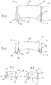
- Fig. 5 to 8 show schematically various embodiments of the geometry of lens body 22 and frame 37th Elemente, already in the construction of the Fig. 3/4 are provided with the same reference numerals, so that in this regard also to the description of the FIGS. 3 and 4 is referenced.
- the lens body 22 is delimited by an entrance surface 23 and the lens front surface 29.
- the shape of a plano-concave lens is preferred, wherein the concave lens front surface 29 particularly preferably corresponds in terms of its curvature of the human cornea, or is slightly flattened.
- the lens front surface 29 may also be aspherical in order to minimize optical aberrations.
- the socket 37 encloses the lens body 22 on a part of its circumference, whereby a connecting surface between the lens body 22 and socket member 37 is formed substantially along a cylindrical lateral surface. Between the edge of the lens body 22 and the neck ring 41 of the socket 37 and the edge 47 of the lens front surface 29 of the lens body 22 serving as a suction channel annular gap 44 is formed.
- the lens edge 47 is cylindrical, the ring inner surface 46, however, formed conical, the cone now opens to the curvature surface K out. Also, here the neck ring 41 extends exactly to the curvature surface K.
- both the lens body 22 on the lens edge 47 are conical (tapering to the eye) and the ring inner surface 46 (widening towards the eye). Furthermore, the axially outermost outline of the attachment ring 41 with respect to the curvature surface K remains. This has the advantage that a complete adjustment of the eye relative to the contact glass 12 is possible and only when additionally applied mechanical pressure of the suction channel is closed by conditioning the cornea.
- Fig. 8 Finally, a construction similar to that Fig. 7 However, both ring inner surface 46 and lens edge 47 are tapered conically tapered to the eye. It is advantageous in this case, the smaller diameter of the support surface of the contact glass 12 on the eye at the same time large diameter of the entrance surface 23rd
- Fig. 9 shows a sectional view of another variant of the contact glass 12 in detail. It is a modification of the contact glass of 3 and 4 why identical elements have been given the same reference numerals.
- the contact glass 12 is constructed in two parts and consists of the lens body 22 which is fixed in a socket 37, for example, glued.
- the lens body 22, which may for example be formed of glass, has the planar entrance surface 23 at which the treatment radiation from the laser treatment device 1 is supplied, and the opposite, patient-side lens front surface 29, which is curved and adapted to the curvature of the human cornea.
- the lens body 22 is made of glass or medically approved plastic, eg. As PMMA or polycarbonate. These materials are also suitable for the version, which may additionally be made of polyuretan or silicone rubber.
- the socket 37 has the connection piece 38, which has the connection piece 39, onto which a vacuum hose is pushed, as well as the vacuum supply line 40 running in the socket 38.
- the supply line 40 opens laterally of the lens body 22 above the neck ring 41 of the socket 37th
- the neck ring 41 sets with its patient-side surface (in the representation of Fig. 3 seen from below), the curvature of the lens front surface 29 away, so that its axially outermost outline in the form of the lower edge 42 in an extension of the curvature of the lens front surface 29 is located. Between this edge 42 and the outer edge of the lens front surface 29, the suction surface 43 is formed.
- the suction surface 43 covers the annular suction channel 44, which is formed in this embodiment by a gap between the socket 37 and lens body 22. In principle, however, a suction channel 44, which lies completely in the material of the holder 37, would also be possible.
- the suction surface 37 is thus formed by a wall which leads from the outermost edge 42 of the attachment ring 41 to the edge of the lens front surface 29.
- suction openings 45 are formed, which are the patient end located end of individual channels 46, which open at its other end in the suction channel 44.
- the suction surface 43 preferably continues the curvature of the lens front surface 29 smoothly (a continuation of a spherical curvature surface being possible, but also an aspherical curvature or a curvature having a larger or smaller curvature radius deviating from the lens front surface 29), the overall transition is largely fluid from the lens front surface 29 to the suction surface 43 given. In any case, the transition has no sharp edges but at most in an annular seam, where the curvature or tilt changes.
- Fig. 10 shows the contact glass 12 of Fig. 9 in a view from the patient side, ie in Fig. 9 from underneath.
- the suction openings 45 are designed here oval and The lens front surface 29 outside a seam 147 between the frame 37 and the lens body 22 in the region of the annular suction surface 43.
- Fig. 11 shows a modified construction, in which case the suction openings 45 are geometrically designed differently, namely in the form of half-ovals, which result in an arcade-shaped structure of the intake 45. Also here is the vacuum connection designed differently, namely as Luer-lock connector.
- the diameter of the annular suction surface 43 and thus also the lens front surface 29 is preferably selected depending on the patient.
- different contact lenses 12 with different diameters of the lens front surface 29 and thus diameter of the annular suction surface 43 are held, so that the suction openings 45 in each case sit on the cornea of the patient to be treated and thus optimal suction is guaranteed.
- An aspiration of conjunctiva in the region of the suction surface 43 is thus excluded.
- coding in the region of the mount 37 is provided.
- the socket is equipped with an RFID chip, the device 1 with a corresponding transmitter / receiver unit.
- the range of the transmitter / receiver unit is limited in space (e.g., 10 cm). If the contact glass is placed in the holder, the device 1 checks the stored information, evaluates it and changes it if necessary. This change is advantageous in single-use contact lenses, because it can be prevented that a repeated use is made.
- the RFID chip can be poured.
- the RFID chip can be sterilized individually or in connection with the entire contact glass.
- Preferable is a gas sterilization with ethylene dioxide (ETO).
- ETO ethylene dioxide
- the treatment apparatus 1 is equipped with an RFID transceiver and reads the stored information (e.g., an ID or use code). Repeated use is prevented either by the fact that the same usage code is only accepted once by the respective device 1, i. the device 1 changes the information in the chip so that a second use is excluded on other devices.
- this principle can be used for any combination of an accessory and a medical device.
- contact between the lens anterior surface 29 and the corneal vertex is first established.
- a contact with the cornea is made in an ever larger surface area of the lens front surface. If the cornea is completely on the lens front surface 29, due to the curvature of the cornea becoming stronger in the edge region of the cornea, no contact is yet established between the axially foremost outline of the attachment ring 41 and the cornea, so that the suction opening 45 is not yet covered by the cornea of the eye , In this state, it is still possible to adjust the eye in contact with the lens front surface 29 so that the optical axis A1 is exactly as desired, for example, coincides with the visual axis. Only when contact glass and eye are further compressed, the cornea also applies to the axially outermost contour 42 of the neck ring 41, whereby the suction channel 44 is closed at the intake ports 45 and the contact glass 12 is attached to the eye.
- the version 37 is z. B. with respect to the neck ring 41 designed so that the axially outermost contour of the edge 42 of the neck ring 41 is not opposite to a curvature surface, which is defined by the curvature of the eye with fully applied to the lens front surface 29 cornea, projecting.
- the edge 42 lies in one embodiment exactly in the imaginary extension of the curvature surface. In simplification, reference can also be made to the curvature of the lens front surface 29.
Landscapes
- Health & Medical Sciences (AREA)
- Ophthalmology & Optometry (AREA)
- Optics & Photonics (AREA)
- Physics & Mathematics (AREA)
- Heart & Thoracic Surgery (AREA)
- Animal Behavior & Ethology (AREA)
- Engineering & Computer Science (AREA)
- Biomedical Technology (AREA)
- Nuclear Medicine, Radiotherapy & Molecular Imaging (AREA)
- Vascular Medicine (AREA)
- Life Sciences & Earth Sciences (AREA)
- Surgery (AREA)
- General Health & Medical Sciences (AREA)
- Public Health (AREA)
- Veterinary Medicine (AREA)
- Eyeglasses (AREA)
- Prostheses (AREA)
- Materials For Medical Uses (AREA)
Description
- Die Erfindung bezieht sich auf ein System umfassend ein Kontaktglas für die Augenchirurgie, das eine zum Aufsetzen auf das Auge ausgebildete Linsenvorderfläche und eine Einrichtung zur Unterdruckbefestigung des Kontaktglases am Auge aufweist.
- Ein solches Kontaktglas ist in der
WO 2005/048895 A1 gezeigt, die sich ansonsten mit der Befestigung des Kontaktglases an einer Laserbehandlungsvorrichtung beschäftigt. - Kontaktgläser in der Augenchirurgie sind Beispiele für Adaptoren, die die Laserbearbeitungsvorrichtung mit einem Objekt mechanisch koppeln. Diese Kopplung ist erforderlich, da die Genauigkeit der Positionierung des Laserstrahls im Objekt in der Regel die bei der Bearbeitung erreichte Präzision vorgibt. Erst die exakte dreidimensionale Positionierung des Laserstrahls in dem Bearbeitungsvolumen, beispielsweise in der Hornhaut des Auges, ermöglicht eine hochgenaue Bearbeitung. Die Fixierung des zu bearbeitenden Objektes wird deshalb durch einen Adapter vorgenommen, der eine genau definierte Lage des Objektes, beispielsweise des Auges gegenüber der Laserbearbeitungsvorrichtung gewährleistet. Der Adapter, der in der Augenchirurgie üblicherweise als Kontaktglas bezeichnet wird, ist damit Teil des Strahlengangs. Ist die äußere Form des zu bearbeitenden Objektes nicht exakt bekannt, hat der Adapter zumeist auch die Funktion, dem Objekt, soweit möglich, eine bestimmte, bei der Applikation eines Laserstrahls vorausgesetzte Form zu geben.
- Da die Vorderfläche der Hornhaut des menschlichen Auges von Patient zu Patient variiert, ist bei der lasergestützten Augenchirurgie regelmäßig ein Adapter in Form eines Kontaktglases vorgesehen. Die
US 2001/0021844 A1 beschreibt ein entsprechendes Kontaktglas, das nicht nur die Fixierung des Auges, sondern auch eine Formgebung der Hornhautvorderfläche bewerkstelligt. Die US-Schrift schlägt vor, zwischen der Hornhaut und dem als Linsenkörper ausgeführten Kontaktglas Unterdruck anzulegen, wodurch die Augenhornhaut an das Kontaktglas gesaugt wird. Durch die derart zwischen Linsenkörper und Augenhornhaut erfolgende Unterdruckbefestigung nimmt die Augenhornhaut automatisch die Form der Linsenkörpervorderfläche (Vorderfläche ist auf den Patienten bezogen) an. Diese Art der Befestigung ist jedoch für den Patienten recht unangenehm, insbesondere wenn die in einer Ausführungsform derUS 2001/0021844 A1 an der Unterseite der Linsenkörper-Fassung vorgesehenen, widerhakenartigen Noppen verwendet werden, die eine verbesserte Befestigung des Kontaktglases am Auge erreichen sollen. - Der Erfindung liegt die Aufgabe zu Grunde, ein Kontaktglas der eingangs genannten Art so fortzubilden, dass eine Überwachung der Anzahl seiner Einsätze ermöglicht wird.
- Diese Aufgabe wird erfindungsgemäß mit einem System gemäß Anspruch 1 gelöst. In einer bevorzugten Ausführungsform ist am Kontaktglas die Linsenvorderfläche ringförmig von einem gegenüber einer gedachten Verlängerung der Linsenvorderfläche nicht vorstehenden Ringspalt oder von einer Vielzahl von Ansaugöffnungen umgeben, durch den/die hindurch Unterdruck auf das Auge wirkt.
- Die Augenhornhaut wird durch mechanischen Druck an die Linsenvorderfläche angelegt bzw. dort gehalten, wobei der mechanische Druck aus einer Ansaugung der Augenhornhaut resultiert, die in einem die Linsenvorderfläche umgebenden ringförmigen Bereich vorgenommen wird. Der ringförmige Bereich weist Ansaugöffnungen auf, die den Unterdruck zuführen. Dieses Vorgehen erreicht zwei wesentliche Vorteile. Zum einen kann der Unterdruck auf die Augenhornhaut so schonend wie möglich aufgebracht werden. Es ist in einer Variante zudem ausgeschlossen, dass die Augenhornhaut ringförmig in einen Ringspalt hineingesaugt wird. Damit ist auch ein unerwünschtes Verstopfen des Saugkanals ausgeschlossen. Zum anderen kann die Patientenseite des Kontaktglases im wesentlichen glatt ausgebildet sein; das Auge wird an eine glatte Fläche angedrückt, die angeordnete Ansaugöffnungen hat. Scharfkantige Einwirkungen auf das Auge sind damit vermieden, bzw. der beim Stand der Technik erforderliche Fertigungsaufwand zur Vermeidung scharfer Kanten an einem Saugring entfällt nun. Die Ausgestaltung schafft also ein Kontaktglas für die Augenchirurgie, das einen in einer Fassung aufgenommenen Linsenkörper aufweist, welcher eine zum Aufsetzen auf das Auge ausgebildete, konkave Linsenvorderfläche aufweist, wobei am Rand der Linsenvorderfläche zwischen dem Linsenkörper und der Fassung ein Ringspalt bzw. ringförmiger Bereich gebildet ist, der zusammen mit dem angelegten Auge als Saugkanal wirkt, über den Unterdruck zum Befestigen des Kontaktglases am Auge applizierbar ist, wobei die Fassung gegenüber einer gedachten Verlängerung der Linsenvorderfläche nicht vorsteht. Der Ringspalt bzw. ringförmige Bereich formt zusammen mit dem angelegten Auge eine weitestgehend luftdichte Kammer, so dass mittels Unterdruck eine Kraft zur Befestigung des Kontaktglases an der Augenhornhaut applizierbar ist.
- Bevorzugt ist die Fassung so ausgebildet, dass bei vollflächig an die Linsenvorderfläche angelegtem Auge der Saugkanal zwischen Ringspalt und Auge noch nicht geschlossen ist.
- Im Gegensatz zu dem in
US 2001/0021844 A1 beschriebenen Vorgehen, wird die Augenhornhaut nicht durch Vakuum direkt an die Linsenvorderfläche angesaugt, sondern durch mechanischen Druck an die Linsenvorderfläche angelegt. Dadurch, dass die Fassung so ausgebildet ist, dass bei vollständig an die Linsenvorderfläche angelegtem Auge der Saugkanal zwischen Ringspalt und Auge noch offen bleibt (die Augenhornhaut den Ringspalt also noch nicht abdeckt) kann in diesem Zustand eine genaue Ausrichtung des Kontaktglases gegenüber dem Auge erfolgen. Erst wenn das Kontaktglas weiter auf das Auge hin gedrückt wird, überdeckt die Augenhornhaut den Ringspalt, wodurch der Saugkanal zwischen Ringspalt und Auge geschlossen ist und die Unterdruckbefestigung wirkt. Das im Ringspalt aufgebrachte Vakuum dient somit nur zur Fixierung des Auges, bewirkt aber nicht direkt die Verformung der Augenhornhaut. Damit ist der gesamte Prozess des Anlegens und Fixierens besser kontrollierbar. - Das durch den Saugkanal aufgebrachte Vakuum dient nur zur Fixierung des Auges, bewirkt aber nicht direkt die Verformung der Augenhornhaut, da kein Vakuum zwischen der Linsenvorderfläche und der Augenhornhaut wirkt. Das erfindungsgemäße Kontaktglas ist also besonders für Patienten geeignet, die in dem Bereich der Hornhaut, der an die Linsenvorderfläche angelegt werden soll, Hornhautschäden, Anomalien oder gar nicht verheilte Schnitte früherer augenchirurgischer Eingriffe haben. Da in diesem Bereich der Augenhornhaut kein Unterdruck wirkt, ist jetzt eine schädigende Wirkung der Kontaktglasbefestigung ausgeschlossen.
- Auf der Patientenseite ist der Übergang zwischen der Linsenvorderfläche und der Fassung (bis auf den Ringspalt) fließend; die Fassung bildet jenseits des Ringspaltes keine Sprungstelle.
- Die Fassung ist geometrisch so gestaltet, dass die Augenhornhaut in einem Zustand, in dem das Auge bereits vollflächig an die Linsenvorderfläche angelegt ist, noch nicht am Fassungsrand, der den Ringspalt begrenzt, anliegt, folglich den Ringspalt noch nicht zum Saugkanal schließt. Dies kann beispielsweise dadurch erreicht werden, dass der axial vorderste Umriss der Fassung gegenüber einer Krümmungsfläche, die die Augenhornhaut hat, wenn das Auge vollständig an der Linsenvorderfläche anliegt, nicht vorsteht oder gegenüber dieser sogar zurückbleibt. Die Form der Krümmungsfläche hängt im wesentlichen von dem Zustand ab, den das Auge bei vollständiger Anlage an die Linsenvorderfläche hat.
- In einer einfachen Gestaltung kann man für die Krümmungsfläche, gegenüber der der axial vorderste Umriss der Fassung nicht vorsteht oder sogar zurückbleibt, auch Bezug auf die Krümmung der Linsenvorderfläche nehmen, so dass dann der axial vorderste Umriss der Fassung gegenüber der gedachten Verlängerung der Linsenvorderfläche nicht vorsteht oder sogar zurückbleibt.
- Mit dem Kontaktglas kann die natürliche Form der Hornhaut bei angelegtem Kontaktglas gewahrt werden, was für den Patienten besonders angenehm ist. Das Auge wird bei geeignetem Krümmungsradius mit minimalen Deformationen an das Kontaktglas gelegt.
- Eine besonders einfache Fertigung erreicht man, wenn man den Ringspalt durch eine oder mehrere Kegelstumpfmantelflächen bzw. konische Flächen an Fassung und/oder Linsenkörper ausbildet. Mit solchen konischen Flächen ist darüber hinaus in der Regel eine weitere Ausführungsform einfach realisiert, bei der sich der Ringspalt vom Auge weg verjüngt und insbesondere am vom Auge abgewandten Ende unter einem spitzen Winkel ≤ 90° zusammenläuft.
- Eine solche Gestaltung des Ringspaltes ist weiter vorteilhaft, weil dadurch effektiv vermieden wird, dass Teile der Augenhornhaut bis in den oberen Bereich des Saugkanals gesaugt werden und diesen dadurch teilweise verstopfen. Die Einleitung des Unterdrucks in den Ringspalt ist dann unkritisch, da immer der gesamte Ringspalt als Saugkanal wirkt und insbesondere der Unterdruckanschluss nicht durch die Augenhornhaut verschlossen werden kann.
- Das Kontaktglas ermöglicht, insbesondere wenn die Krümmungsfläche der Linsenvorderfläche etwas flacher gekrümmt ist, als die Augenhornhaut, ein besonders einfaches Aufsetzen des Kontaktglases auf die Augenhornhaut. Bei Annäherung an das Kontaktglas berührt zunächst nur der zentrale Bereich der Augenhornhaut, also der Augenhornhautscheitel, die Linsenvorderfläche. Bei zunehmendem Aufsetzen liegt nach und nach die Augenhornhaut an der vollständigen Linsenvorderfläche an, wobei auch in diesem Zustand der Saugkanal noch nicht geschlossen ist und der Patient das Auge trotz teilweiser Deformation noch frei bewegen kann. In diesem Zustand ist eine einfache Ausrichtung des Kontaktglases gegenüber dem Auge möglich. Ist die gewünschte Justierlage erreicht, so wird der Abstand zwischen Kontaktglas und Patientenauge noch etwas verringert, wodurch der Ringspalt von der Hornhaut des Auges geschlossen ist und das Auge durch Unterdruck gegenüber dem Kontaktglas fixiert ist.
- Die Krümmungsfläche, welche von der Linsenvorderfläche dem Auge als Soll-Form aufgeprägt ist, kann applikationsabhängig gewählt werden. Insbesondere sind auch asphärische Krümmungsflächen möglich, die es erlauben, optische Abbildungsfehler beim Einbringen von Behandlungs-Laserstrahlung zu minimieren. Auch kann die Linsenvorderfläche sphärisch mit einem Radius von 5-30 mm sein. Ein Radius der etwas geringer ist als der der menschlichen Hornhaut, also z. B. zwischen 15 und 25 mm ist besonders bevorzugt. Diese Sphärizität ist durch die erfindungsgemäße Ausgestaltung ohne Probleme möglich, da, anders als beim Stand der Technik in Form der
US 2001/0021844 A1 , keine Gefahr besteht, dass die Augenhornhaut den Unterdruck-Saugkanal so verschließt, dass nur eine unvollständige Befestigung des Kontaktglases am Auge erfolgt. - Vorzugsweise sind die die Linsenvorderfläche ringförmig umgebenden Ansaugöffnungen als Teil eines Saugkanals gebildet. Weiter ist günstigerweise die Ausbildung so, dass bei vollständig an die Linsenvorderfläche angelegtem Auge die Ansaugöffnungen noch nicht von der Augenhornhaut überdeckt sind, mithin keine Ansaugung erfolgt. In diesem Zustand kann dann eine genaue Ausrichtung des Kontaktglases gegenüber dem Auge erfolgen. Erst wenn das Kontaktglas weiter auf das Auge hingedrückt wird, überdeckt die Augenhornhaut auch die Ansaugöffnungen, wodurch die Unterdruckbefestigung wirkt.
- Diese Ausgestaltung des Kontaktglases kann beispielsweise dadurch erreicht werden, dass in dem ringförmigen Bereich, in dem die Ansaugöffnungen liegen, eine Schrägstellung gegenüber der optischen Achse und/oder konkave Krümmung vorgesehen ist, z. B. eine, die etwas geringer ist, als die Krümmung der Augenhornhaut. Auch kann natürlich die Linsenvorderfläche konkav sein.
- Ein zweckmäßiger und besonders einfach zu fertigender Aufbau des Kontaktglases besteht darin, dass die Linsenvorderfläche an einem Linsenkörper ausgebildet ist, der in einer Fassung gehalten ist, wobei die Ansaugöffnungen in der Fassung gebildet sind. Die eben genannte zweistufige Befestigung, bei der die Unterdruckbefestigung erst dann wirkt, wenn das Kontaktglas im justierten Zustand weiter auf das Auge hingedrückt wird, kann dann einfach dadurch erreicht werden, dass der axial vorderste Umriss der Fassung gegenüber einer Krümmung, die die Augenhornhaut hat, wenn das Auge vollständig an der Linsenvorderfläche anliegt, nicht vorsteht oder gegenüber dieser sogar zurückbleibt. Der Teil der Fassung, der die Ansaugöffnungen aufweist, wird zweckmäßigerweise möglichst nahtlos an die Linsenvorderfläche anschließen.
- Eine besonders einfache Fertigung erreicht man, wenn der Saugkanal zwischen Fassung und Linsenkörper gebildet ist und Einzelkanäle vom Saugkanal durch eine Wandung der Fassung in die Ansaugöffnungen münden. Der Saugkanal kann dann beispielsweise ein ringförmiger Spalt zwischen Fassung und Linsenkörper sein, der patientenseitig von einer Wandung der Fassung überdeckt ist, die von einem außengelegen Rand der Fassung bis an den Rand der Linsenvorderfläche reicht. Durchbrüche in dieser Wandung bilden die Einzelkanäle und damit die Ansaugöffnungen.
- Die Anzahl der Ansaugöffnungen ist zahlenmäßig nicht festgelegt, wird aber fertigungsbedingt entsprechend zu wählen sein. Die Form der Ansaugöffnungen kann auch nach Fertigungsgegebenheiten ausgewählt werden, insbesondere können sie rund, oval oder rechteckig sein. Um Verletzung der Augenhornhaut auszuschließen, sollte bei der Fertigung natürlich auf Gratfreiheit geachtet werden.
- Die Krümmungsfläche, welche von der Linsenvorderfläche dem Auge als Soll-Form aufgeprägt ist, kann applikationsabhängig gewählt werden. Insbesondere sind auch asphärische Krümmungsflächen möglich, die es erlauben, optische Abbildungsfehler beim Einbringen von Behandlungs-Laserstrahlung zu minimieren.
- Mit dem Kontaktglas kann die natürliche Form der Hornhaut bei angelegtem Kontaktglas gewahrt werden, was für Patienten besonders angenehm ist. Das Auge wird bei geeigneter Krümmung der Linsenvorderfläche mit minimalen Deformationen an das Kontaktglas gelegt. Die Linsenvorderfläche kann dabei sphärisch gekrümmt mit einem Krümmungsradius von 5-30 mm sein; bevorzugt ist ein Radius der etwas größer ist, als der des menschlichen Auges, und deshalb im Bereich von 15-25 mm liegt.
- Die ringförmig liegenden Ansaugöffnungen vermeiden effektiv, dass Teile der Augenhornhaut bis in den oberen Bereich des Saugkanals gesaugt werden und diesen dadurch teilweise verstopfen. Die Einleitung des Unterdrucks in den Saugkanal ist folglich unkritisch, da immer der gesamte Saugkanal wirkt und insbesondere der Unterdruckanschluss nicht durch die Augenhornhaut verschlossen werden kann.
- Das Kontaktglas ermöglicht, insbesondere wenn die Krümmungsfläche der Linsenvorderfläche etwas flacher gekrümmt ist, als die Augenhornhaut, ein besonders einfaches Aufsetzen des Kontaktglases auf die Augenhornhaut. Bei Annäherung an das Kontaktglas berührt zunächst nur der zentrale Bereich der Augenhornhaut, also der Augenhornhautscheitel, die Linsenvorderfläche. Bei zunehmendem Aufsetzen liegt nach und nach die Augenhornhaut an der vollständigen Linsenvorderfläche an, wobei auch in diesem Zustand die Ansaugöffnungen noch nicht abgedeckt sind und der Patient das Auge trotz teilweiser Deformation noch frei bewegen kann. In diesem Zustand ist eine einfache Ausrichtung des Kontaktglases gegenüber dem Auge möglich. Ist die gewünschte Justierlage erreicht, so wird der Abstand zwischen Kontaktglas und Patientenauge noch etwas verringert, wodurch der Ringspalt von der Hornhaut des Auges geschlossen ist und das Auge durch Unterdruck gegenüber dem Kontaktglas fixiert ist.
- Es hat sich gezeigt, dass bei der Unterdruckbefestigung eines augenchirurgischen Kontaktglases das Ansaugen von Bindehaut (Sclera) an den Mitteln der Unterdruckbefestigung vermieden werden sollte, da ansonsten eine unzureichende Fixierung der Augenhornhaut, an der der chirurgische Eingriff erfolgen soll, auftreten kann. Die Unterdruckbefestigung wirkt also vorzugsweise ausschließlich an der Hornhaut und nicht der Sclera des Auges.
- Die Erfindung sieht ganz unabhängig von der sonstigen Gestaltung des Kontaktglases und insbesondere unabhängig von der Gestaltung der Mittel zur Unterdruckbefestigung ein Kontaktglas für die Augenchirurgie vor, das eine zum Aufsetzen auf das Auge ausgebildete Linsenvorderfläche und eine Einrichtung zur Unterdruckbefestigung des Kontaktglases am Auge aufweist und weiter dadurch gekennzeichnet ist, dass am Kontaktglas ein einen geometrischen oder optischen Parameter des Kontaktglases kodierendes Kodierelement vorgesehen ist. Zweckmäßigerweise handelt es sich bei dem geometrischen oder optischen Parameter um den Durchmesser der Linsenvorderfläche. Das Kodierelement ist am Kontaktglas günstigerweise so angebracht, dass ein Anwender, d. h. ein Augenchirurg, von außen den gewünschten geometrischen oder optischen Parameter, beispielsweise den gewünschten Durchmesser der Linsenvorderfläche erkennen kann. Als Kodierelement kommt beispielsweise ein Strichcode, eine Ziffern- oder Buchstabenkennung oder auch ein geometrischer oder Farbcode in Frage. Besonders bevorzugt ist ein Kontaktglas, das eine Farbmarkierung trägt, wobei die Farbmarkierung dem Durchmesser der Linsenvorderfläche oder einem anderen geometrischen oder optischen Parameter des Kontaktglases zugeordnet ist. Fertigt man das Kontaktglas zweiteilig, d. h. aus einem die Linsenvorderfläche aufweisenden Linsenkörper sowie einer den Linsenkörper halternden Fassung, wird man das Kodierelement günstigerweise an der Fassung anordnen. Im Falle in der Farbcodierung kann beispielsweise die Fassung selbst eingefärbt werden.
- Natürlich ist auch eine Variante möglich mit einem Informationsträger und mit einer Vorrichtung zum drahtlosen Auslesen und/oder Verändern der dort gespeicherten Information. Die Informationsübertragung erfolgt durch elektromagnetische Signale (z.B. im Radiofrequenzbereich zwischen 100kHz und 1GHz oder wie in
WO 2005039462 A1 beschrieben). - Die in Verbindung mit dem Kontaktglas stehende Vorrichtung zum drahtlosen Auslesen und/oder Verändern der gespeicherten Information kann über einen Sender und Empfänger verfügen. Der Sender kann mit seinem Signal Energie an den Informationsspeicher übertragen, die dieser wiederum zur Aussendung von in ihm gespeicherter Information in Form eines Antwortsignals nutzt.
- Es besteht die Möglichkeit mittels Signal vom Sender die im Informationsspeicher gespeicherte Information zu verändern. (Bei erneuter Informationsübertragung vom Zubehörteil zum Produkt wird dann die veränderte Information übertragen.) Der Informationsspeicher und die Fassung können eine mechanische Einheit bilden und es besteht die Möglichkeit, das Zubehörteil mit dem integrierten Informationsspeicher zu sterilisieren.
- Damit ein Anwender ein Kontaktglas mit den gewünschten Parametern auswählen kann, ist die Kodierung vorteilhaft als optisch wahrnehmbare Kodierung ausgebildet, so dass ein Chirurg schnell und zielsicher das gewünschte Kontaktglas auswählen kann.
- Die Erfindung wird nachfolgend unter Bezugnahme auf die Zeichnungen beispielhalber noch näher erläutert. In den Zeichnungen zeigt:
- Fig.1
- eine schematische Darstellung einer Laserbearbeitungsvorrichtung für die Augenchirurgie,
- Fig. 2
- eine schematische Darstellung der Augenhornhaut eines Patienten,
- Fig. 3 und 4
- ein Kontaktglas für die Laserbearbeitungsvorrichtung der
Fig. 1 , wobeiFig. 3 eine Draufsicht undFig. 4 eine Schnittdarstellung ist, - Fig. 5 bis 8
- Schema-Schnittdarstellungen von Kontaktgläsern ähnlich dem der
Fig. 3/4 , - Fig.9
- eine Schnittdarstellung einer weiteren Variante eines Kontaktglases für die Laserbearbeitungsvorrichtung der
Fig. 1 , - Fig. 10
- eine Draufsicht auf das Kontaktglas der
Fig. 9 von unten (bezogen aufFig. 3 ) und - Fig. 11
- eine Darstellung ähnlich der
Fig. 10 für eine weitere Bauweise eines Kontaktglases. -
Fig. 1 zeigt ein Behandlungsgerät für ein augenchirurgisches Verfahren ähnlich dem in derEP 1159986 A1 bzw. derUS 5549632 beschriebenen. Das Behandlungsgerät 1 derFigur 1 dient dazu, an einem Auge 2 eines Patienten eine Fehlsichtigkeitskorrektur gemäß dem bekannten Femtosekunden-LASIK-Verfahren auszuführen. Dazu weist das Behandlungsgerät 1 einen Laser 3 auf, der gepulste Laser-Strahlung abgibt. Die Pulsdauer liegt dabei z. B. im Femtosekundenbereich, und die Laserstrahlung wirkt mittels nichtlinearer optischer Effekte in der Hornhaut auf die eingangs beschriebene Art und Weise. Der vom Laser 3 entlang einer optischen Achse A1 abgegebene Behandlungsstrahl 4 fällt dabei auf einen Strahlteiler 5, der den Behandlungsstrahl 4 auf eine Scaneinrichtung 6 leitet. Die Scaneinrichtung 6 weist zwei Scanspiegel 7 und 8 auf, die um zueinander orthogonale Achsen drehbar sind, so dass die Scaneinrichtung 6 den Behandlungsstrahl 4 zweidimensional ablenkt. Eine verstellbare Projektionsoptik 9 fokussiert den Behandlungsstrahl 4 auf bzw. in das Auge 2. Die Projektionsoptik 9 weist dabei zwei Linsen 10 und 11 auf. Das Behandlungsgerät 1 stellt eine Laserbearbeitungsvorrichtung dar. - Der Linse 11 ist ein als Adapter wirkendes Kontaktglas 12 nachgeordnet, das über eine Halterung H fest mit der Linse 11 und damit dem Strahlengang des Behandlungsgerätes 1 verbunden ist. Das noch näher zu beschreibende Kontaktglas 12 liegt an der Hornhaut des Auges 2 an. Die optische Kombination aus Behandlungsgerät 1 mit daran befestigtem Kontaktglas 12 bewirkt, dass der Behandlungsstrahl 4 in einem in der Hornhaut des Auges 2 gelegenen Fokus 13 gebündelt wird.
- Die Scaneinrichtung 6 wird ebenso wie der Laser 3 und die Projektionsoptik 9 über (nicht näher bezeichnete) Steuerleitungen von einem Steuergerät 14 angesteuert. Das Steuergerät 14 bestimmt dabei die Lage des Fokus 13 sowohl quer zur optischen Achse A1 (durch die Scanspiegel 7 und 8) sowie in Richtung der optischen Achse A1 (durch die Projektionsoptik 9).
- Das Steuergerät 14 liest weiter einen Detektor 15 aus, der von der Hornhaut rückgestreute Strahlung, die den Strahlteiler 5 als Rückstrahlung 16 passiert, ausliest. Mittels des Detektors 15 kann der Betrieb des Lasers 3 sehr exakt gesteuert werden.
- Das Kontaktglas 12 sorgt dafür, dass die Hornhaut des Auges 2 eine gewünschte Soll-Form erhält. Das Auge 2 befindet sich aufgrund der Anlage der Hornhaut 17 am Kontaktglas 12 in vorbestimmter Lage zum Kontaktglas 12 und somit zum damit verbundenen Behandlungsgerät 1.
- Dies ist schematisch in
Fig. 2 dargestellt, die einen Schnitt durch die Augenhornhaut 17 zeigt. Um eine exakte Positionierung des Fokus 13 in der Augenhornhaut 17 zu erreichen, muss die Krümmung der Augenhornhaut 17 berücksichtigt werden. Die Augenhornhaut 17 weist eine Ist-Form 18 auf, die von Patient zu Patient unterschiedlich ist. Der Adapter 12 liegt nun an der Augenhornhaut 17 derart an, dass er diese in eine gewünschte Soll-Form 19 verformt. Der genaue Verlauf der Soll-Form 19 hängt dabei von der Krümmung der dem Auge 2 zugewandten Linsenvorderfläche des Kontaktglases 12 ab. Durch den Adapter 12 sind bekannte geometrische und optische Verhältnisse für das Einbringen und Fokussieren des Behandlungsstrahls 4 in die Hornhaut 17 gegeben. Da die Hornhaut 17 am Kontaktglas 12 anliegt und dieses wiederum über die Halterung H gegenüber dem Strahlengang des Behandlungsgerätes 1 ortsfest ist, kann der Fokus 13 durch Ansteuerung der Scaneinrichtung 6 sowie der verstellbaren Projektionsoptik 9 dreidimensional exakt in der Hornhaut 17 positioniert werden. - Die
Fig. 3 und 4 zeigen eine Ausführungsform des Kontaktglases 12 im Detail;Fig. 4 ist eine Schnittdarstellung,Fig. 3 eine Ansicht des Kontaktglases 12 von vorne (inFig. 4 von unten), d. h. in Sichtweite des Patienten. Das Kontaktglas 12 ist zweiteilig aufgebaut und besteht aus einem Linsenkörper 22, der in einer Fassung 37 befestigt ist, beispielsweise an einer Klebestelle 43 eingeklebt ist. Der Linsenkörper besteht aus Glas oder einem medizinisch zugelassenem Kunststoff, z.B. PMMA oder Polycarbonat. Diese Substanzen kommen auch für die Fassung in Frage, die zusätzlich noch aus Polyuretan oder Silikonkautschuk sein kann. Durch Andrücken des Kontaktglases 12 auf die Augenhornhaut 17 verleiht die Linsenvorderfläche 29 des in der Fassung 37 gehaltenen Linsenkörpers 22 der Augenhornhaut 17 die gewünschte Soll-Form 19. - Zum Bereitstellen des Unterdrucks weist die Fassung 37 einen Stutzen 38 auf, der über einen Luer-Lock-Anschluss 39 sowie eine im Stutzen verlaufende Unterdruck-Zuleitung 40 verfügt. Die Zuleitung 40 mündet seitlich des Linsenkörpers 22 oberhalb eines Ansatzringes 41 der Fassung 37. Zwischen einer dem Linsenkörper 22 zugewandten Ringinnenfläche 46 des Ansatzringes 41 und dem in dieser Ausführungsform kegelstumpfförmig ausgebildeten Linsenrand 47 ist ein Ringspalt 44 gebildet, der mit der Zuleitung 40 in Verbindung steht und als Saugkanal wirkt, durch den ringförmig Unterdruck auf die Augenhornhaut angebracht werden kann. Mittels Unterdruck am Luer-Lock-Anschluss 39 wird somit das Kontaktglas 12 so am Auge befestigt, dass die Hornhaut durch mechanischen Druck an die Linsenvorderfläche 29 angelegt wird, wodurch die Soll-Form 19 erreicht ist.
- Der Ansatzring 41 steht bezogen auf die optische Achse A1 gegenüber der Linsenvorderfläche 29 vor.
- Bei Aufsetzen des Kontaktglases auf die Augenhornhaut wird zuerst ein Kontakt zwischen der Linsenvorderfläche 29 und dem Hornhautscheitel hergestellt. Mit weiterem Anlegen der Augenhornhaut an die Linsenvorderfläche 29 wird in einem immer größerem Flächenbereich der Linsenvorderfläche ein Kontakt zur Augenhornhaut hergestellt. Liegt die Augenhornhaut vollständig an der Linsenvorderfläche 29 an, ist aufgrund der im Randbereich der Augenhornhaut stärker werdenden Krümmung der Augenhornhaut noch kein Kontakt zwischen der axial vordersten Umrisslinie des Ansatzringes 41 und der Augenhornhaut hergestellt, so dass der durch den Ringspalt 44 bereitgestellte Saugkanal noch nicht von der Augenhornhaut geschlossen ist. In diesem Zustand ist es also noch möglich, das Auge in Anlage an der Linsenvorderfläche 29 so zu justieren, dass die optische Achse A1 genau wie gewünscht liegt, beispielsweise mit der Sehachse übereinstimmt. Erst wenn Kontaktglas und Auge weiter zusammengedrückt werden, legt sich die Augenhornhaut auch an die axial vorderste Umrisslinie 45 des Ansatzringes 41 an, wodurch der Saugkanal am Ringspalt 44 geschlossen und das Kontaktglas 12 am Auge befestigt ist.
- Die Fassung 37 ist also bezüglich des Ansatzringes 41 so gestaltet, dass die axial vorderste Umrisslinie 45 des Ansatzringes 41 nicht gegenüber der einer Krümmungsfläche, die durch die Krümmung des Auges bei vollständig an die Linsenvorderfläche 29 angelegter Augenhornhaut definiert ist, vorsteht. Der Ansatzring 41 liegt in einer Ausführungsform genau in der gedachten Verlängerung der Krümmungsfläche. In Vereinfachung kann auch Bezug auf die Krümmung der Linsenvorderfläche 29 genommen werden.
- Durch die sich vom Auge spitzwinklig verjüngende Form des Ringspaltes 44 ist zuverlässig verhindert, dass Teile der Hornhaut bis in den Bereich des Zuleitung 40 gesaugt werden und diese dadurch zumindest teilweise verstopfen oder zulegen. Auch ist ein Verstopfen des Saugkanals 44 vermieden, so dass eine ringförmige Applikation des Unterdrucks sichergestellt ist.
- Die
Fig. 5 bis 8 zeigen schematisch verschiedene Ausführungsformen der Geometrie von Linsenkörper 22 und Fassung 37. Elemente, die schon in der Bauweise derFig. 3/4 vorhanden sind, sind mit denselben Bezugzeichen versehen, so dass diesbezüglich auch auf die Beschreibung zu denFiguren 3 und 4 verwiesen wird. - Wiederum weist das Kontaktglas 12 den Linsenkörper 22 auf, der in der Fassung 37 gehalten ist. Der Linsenkörper 22 wird begrenzt durch eine Eintrittsfläche 23 und die Linsenvorderfläche 29. Bevorzugt ist die Form einer plan-konkaven Linse, wobei die konkave Linsenvorderfläche 29 besonders bevorzugt hinsichtlich ihrer Krümmung der menschlichen Hornhaut entspricht, oder etwas flacher gekrümmt ist. Möglich sind jedoch auch andere Formen, insbesondere kann die Linsenvorderfläche 29 auch asphärisch sein, um optische Abbildungsfehler zu minimieren.
- Die Fassung 37 umschließt den Linsenkörper 22 auf einem Teil ihres Umfanges, wodurch eine Verbindungsfläche zwischen Linsenkörper 22 und Fassungselement 37 im wesentlichen entlang einer zylindrischen Mantelfläche gebildet ist. Zwischen dem Rand des Linsenkörpers 22 und dem Ansatzring 41 der Fassung 37 und dem Rand 47 der Linsenvorderfläche 29 des Linsenkörpers 22 ist der als Saukanal dienende Ringspalt 44 gebildet.
- Zur Ausführung dieses Ringspaltes kann nun, wie die
Fig. 5 bis 8 zeigen, entweder die Ringinnenfläche 46 des Ansatzrings 41 und/oder der Linsenrand 47 konisch ausgebildet, d. h. schräg gegenüber der optischen Achse A1 verlaufend sein. In der Ausführungsform derFig. 5 ist der Linsenrand 47 konisch, die Ringinnenfläche 46 zylindrisch. Weiter ist deutlich zu sehen, dass der Ansatzring 41 gegenüber der bereits genannten Krümmungsfläche K, die die Krümmung der angelegten Augenhornhaut vorgegeben ist, nicht vorsteht, sondern eher etwas zurückbleibt. Die Bauweise derFig. 5 hat den Vorteil, dass eine einfache, im wesentlichen rohrförmige Fassung 37 verwendet werden kann. Weiter ist der Durchmesser der Linsenvorderfläche 29 kleiner, als der der Eintrittsfläche 23. - Den umgekehrten Fall zeigt die
Fig. 6 , hier ist der Linsenrand 47 zylindrisch, die Ringinnenfläche 46 hingegen konisch ausgebildet, wobei der Konus sich nun zur Krümmungsfläche K hin öffnet. Auch reicht hier der Ansatzring 41 exakt bis an die Krümmungsfläche K. - In der Bauweise gemäß
Fig. 7 sind sowohl der Linsenkörper 22 am Linsenrand 47 konisch (zum Auge verjüngend) als auch die Ringinnenfläche 46 (zum Auge hin aufweitend). Weiter bleibt die axial vorderste Umrisslinie des Ansatzringes 41 gegenüber der Krümmungsfläche K zurück. Dies hat den Vorteil, dass ein vollständiges Justieren des Auges gegenüber dem Kontaktglas 12 möglich ist und erst bei zusätzlich aufgebrachten mechanischem Druck der Saugkanal durch Anlage der Augenhornhaut geschlossen wird. -
Fig. 8 schließlich zeigt eine Bauweise ähnlich derFig. 7 , jedoch sind sowohl Ringinnenfläche 46 als auch Linsenrand 47 konisch zum Auge verjüngt ausgebildet. Vorteilhaft ist in diesem Fall der kleinere Durchmesser der Auflagefläche des Kontaktglases 12 auf dem Auge bei gleichzeitig großem Durchmesser der Eintrittsfläche 23. -
Fig. 9 zeigt eine Schnittdarstellung einer weiteren Variante des Kontaktglases 12 im Detail. Es handelt sich dabei um eine Abwandlung des Kontaktglases derFig. 3 und 4 , weshalb gleiche Elemente mit den gleichen Bezugzeichen versehen wurden. Das Kontaktglas 12 ist zweiteilig aufgebaut und besteht aus dem Linsenkörper 22, der in einer Fassung 37 befestigt, beispielsweise eingeklebt ist. Der Linsenkörper 22, der beispielsweise aus Glas ausgebildet sein kann, hat die planare Eintrittsfläche 23, an der die Behandlungsstrahlung vom Laserbehandlungsgerät 1 zugeführt wird, und die gegenüberliegende, patientenseitig gelegenen Linsenvorderfläche 29, die gekrümmt und der Krümmung der menschlichen Hornhaut angepasst ist. Durch Andrücken des Kontaktglases 12 auf die Augenhornhaut 17 verleiht die Linsenvorderfläche 29 des in der Fassung 37 gehaltenen Linsenkörpers 22 der Augenhornhaut 17 die gewünschte Sollform 19. Der Linsenkörper 22 besteht aus Glas oder medizinisch zugelassenem Kunststoff, z. B. PMMA oder Polycarbonat. Diese Materialien kommen auch für die Fassung in Frage, die zusätzlich noch aus Polyuretan oder Silikonkautschuk sein kann. - Zum Bereitstellen des Unterdrucks weist die Fassung 37 den Stutzen 38 auf, der über den Anschlussstutzen 39, auf den ein Unterdruckschlauch aufgeschoben wird, sowie die im Stutzen 38 verlaufende Unterdruckzuleitung 40 verfügt. Die Zuleitung 40 mündet seitlich des Linsenkörpers 22 oberhalb des Ansatzringes 41 der Fassung 37.
- Der Ansatzring 41 setzt mit seiner patientenseitig gelegenen Fläche (in der Darstellung der
Fig. 3 von unten gesehen) die Krümmung der Linsenvorderfläche 29 fort, so dass sein axial äußerster Umriss in Form des unteren Randes 42 in einer Verlängerung der Krümmung der Linsenvorderfläche 29 liegt. Zwischen diesem Rand 42 und dem Außenrand der Linsenvorderfläche 29 ist die Ansaugfläche 43 gebildet. - Die Ansaugfläche 43 überdeckt den ringförmigen Saugkanal 44, der in dieser Ausführungsform durch einen Spalt zwischen Fassung 37 und Linsenköper 22 gebildet ist. Prinzipiell wäre aber auch ein Saugkanal 44, der vollständig im Material der Fassung 37 liegt, möglich. In der in
Fig. 9 gezeigten Ausführungsform ist die Ansaugfläche 37 also durch eine Wandung gebildet, die vom äußersten Rand 42 des Ansatzringes 41 zum Rand der Linsenvorderfläche 29 hin führt. In der Ansaugfläche 43, d. h. in dieser Wandung, sind Ansaugöffnungen 45 gebildet, die das patientenseitig gelegene Ende von Einzelkanälen 46 sind, welche an ihrem anderen Ende in den Saugkanal 44 münden. - Am Unterdruck-Anschluss 39 angelegter Unterdruck gelangt also durch die Unterdruckzuleitung 40 in den Saugkanal 44 und wirkt dort durch die ringförmig die Linsenvorderfläche 29 umgebenden Ansaugöffnungen 45 auf die Augenhornhaut.
- Da die Ansaugfläche 43 die Krümmung der Linsenvorderfläche 29 bevorzugt glatt fortsetzt (wobei eine Fortsetzung einer sphärischen Krümmungsfläche möglich ist, jedoch auch eine asphärische Krümmung oder eine Krümmung mit einem gegenüber der Linsenvorderfläche 29 abweichenden, größeren oder kleineren Krümmungsradius), ist insgesamt ein weitgehend fließender Übergang von der Linsenvorderfläche 29 auf die Ansaugfläche 43 gegeben. Auf jeden Fall hat der Übergang keine scharfen Kanten sondern besteht höchstens in einer ringförmigen Nahtstelle, an der die Krümmung oder Neigung wechselt.
-
Fig. 10 zeigt das Kontaktglas 12 derFig. 9 in einer Ansicht von der Patientenseite her, also inFig. 9 von unten. Wie gut zu sehen ist, sind die Ansaugöffnungen 45 hier oval ausgestaltet und umgeben die Linsenvorderfläche 29 außerhalb einer Nahtstelle 147 zwischen der Fassung 37 und dem Linsenkörper 22 im Bereich der ringförmigen Ansaugfläche 43. -
Fig. 11 zeigt eine abgewandelte Bauweise, wobei hier die Ansaugöffnungen 45 geometrisch anders gestaltet sind, nämlich in Form von halben Ovalen, die eine arkadenförmige Struktur der Ansaugöffnungen 45 ergeben. Auch ist hier der UnterdruckAnschluss anders gestaltet, nämlich als Luer-Lock-Anschluss. - Der Durchmesser der ringförmigen Ansaugfläche 43 und damit auch der Linsenvorderfläche 29 ist vorzugsweise patientenabhängig gewählt. Es sind also für ein Behandlungsgerät verschiedene Kontaktgläser 12 mit unterschiedlichen Durchmessern der Linsenvorderfläche 29 und damit Durchmesser der ringförmigen Ansaugfläche 43 vorgehalten, so dass die Ansaugöffnungen 45 in jedem Fall auf der Cornea des zu behandelnden Patienten aufsitzen und somit eine optimale Ansaugung gewährleistet ist. Eine Ansaugung von Bindehaut im Bereich der Ansaugfläche 43 ist somit ausgeschlossen. Um dem Anwender die Unterscheidung zwischen verschiedenen Kontaktgläsern 12, beispielsweise von Kontaktgläsern mit verschiedenen Durchmessern der Linsenvorderfläche 29 (und damit Ansaugfläche 43) oder mit verschiedenen Krümmungsradien zu erleichtern, ist eine Kodierung im Bereich der Fassung 37 vorgesehen.
- Dazu ist die Fassung mit einem RFID-Chip ausgestattet, das Gerät 1 mit einer entsprechenden Sender/Empfänger-Einheit. Die Reichweite der Sender/Empfänger-Einheit ist räumlich eng begrenzt (z.B. 10 cm). Wird das Kontaktglas in die Halterung gesetzt, prüft das Gerät 1 die gespeicherte Information, wertet sie aus und verändert sie gegebenenfalls. Diese Veränderung ist bei einmalig zu verwendenden Kontaktgläsern vorteilhaft, weil dadurch verhindert werden kann, dass eine wiederholte Verwendung erfolgt.
- Konkret kann der RFID-Chip eingegossen werden. Der RFID-Chip kann einzeln oder auch im Zusammenhang mit dem ganzen Kontaktglas sterilisiert werden. Zu bevorzugen ist eine Gassterilisation mit Ethylen-Dioxid (ETO). Das Behandlungsgerät 1 ist mit einem RFID-Sender-Empfänger ausgerüstet und liest die gespeicherte Information (z.B. eines ID- oder Benutzungscodes). Eine mehrmalige Verwendung ist entweder dadurch verhindert, dass der gleiche Benutzungscode nur einmal vom jeweiligen Gerät 1 akzeptiert wird, d.h. das Gerät 1 verändert die Information im Chip so, dass eine zweite Verwendung auch an anderen Geräten ausgeschlossen ist.
- Dieses Prinzip kann natürlich für beliebige Kombinationen aus einem Zubehörteil und einem medizintechnischen Gerät eingesetzt werden.
- Um beim Einsatz des Kontaktglases 12 die Beobachtung des Patientenauges zu erleichtern, ist es möglich, durch die Fassung 37 hindurch Licht von einer Lichtquelle zum Behandlungsort einzustrahlen. Dies ist beispielsweise in der
DE 10353264 A1 beschrieben. Die nun lediglich im Bereich der Ansaugöffnungen 45 durchbrochene Ansaugfläche 43 erleichtert dabei die Einkopplung der Strahlung erheblich und die in derDE 10353264 A1 beschriebenen optischen Mittel, die zum Ausgleichen der optischen Wirkung eines ringförmig offenen Saugkanals vorgesehen sind, müssen nicht mehr angewandt werden. - Bei Aufsetzen des Kontaktglases auf die Augenhornhaut wird zuerst ein Kontakt zwischen der Linsenvorderfläche 29 und dem Hornhautscheitel hergestellt. Mit weiterem Anlegen der Augenhornhaut an die Linsenvorderfläche 29 wird in einem immer größerem Flächenbereich der Linsenvorderfläche ein Kontakt zur Augenhornhaut hergestellt. Liegt die Augenhornhaut vollständig an der Linsenvorderfläche 29 an, ist aufgrund der im Randbereich der Augenhornhaut stärker werdenden Krümmung der Augenhornhaut noch kein Kontakt zwischen der axial vordersten Umrisslinie des Ansatzringes 41 und der Augenhornhaut hergestellt, so dass die Ansaugöffnung 45 noch nicht von der Augenhornhaut überdeckt sind. In diesem Zustand ist es also noch möglich, das Auge in Anlage an der Linsenvorderfläche 29 so zu justieren, dass die optische Achse A1 genau wie gewünscht liegt, beispielsweise mit der Sehachse übereinstimmt. Erst wenn Kontaktglas und Auge weiter zusammengedrückt werden, legt sich die Augenhornhaut auch an die axial vorderste Umrisslinie 42 des Ansatzringes 41 an, wodurch der Saugkanal 44 an den Ansaugöffnungen 45 geschlossen und das Kontaktglas 12 am Auge befestigt ist.
- Die Fassung 37 ist z. B. bezüglich des Ansatzringes 41 so gestaltet, dass die axial vorderste Umrisslinie des Randes 42 des Ansatzringes 41 nicht gegenüber der einer Krümmungsfläche, die durch die Krümmung des Auges bei vollständig an die Linsenvorderfläche 29 angelegter Augenhornhaut definiert ist, vorsteht. Der Rand 42 liegt in einer Ausführungsform genau in der gedachten Verlängerung der Krümmungsfläche. In Vereinfachung kann auch Bezug auf die Krümmung der Linsenvorderfläche 29 genommen werden.
- Natürlich können die hier geschilderten geometrischen Ausgestaltungen auch einzeln oder in anderen, nicht ausdrücklich gezeigten oder beschriebenen Kombinationen vorteilhaft eingesetzt werden.
- Natürlich können die hier geschilderten geometrischen Ausgestaltungen auch einzeln oder in anderen, nicht ausdrücklich gezeigten oder beschriebenen Kombinationen vorteilhaft eingesetzt werden.
Claims (17)
- System aus einem eine Sende/Lese-Einheit aufweisenden Behandlungsgerät (1) und einem Kontaktglas für die Augenchirurgie, das eine zum Aufsetzen auf das Auge (2) ausgebildete Linsenvorderfläche (29) und eine Einrichtung zur Unterdruckbefestigung des Kontaktglases (12) am Auge (2) aufweist, wobei am Kontaktglas (12) ein einen geometrischen oder optischen Parameter kodierendes Kodierelement vorgesehen ist, das ein einen ID-Code speichernder RFID-Chip ist, der zur Zusammenwirkung mit der Sende/Lese-Einheit ausgebildet ist, und wobei die Sende/Lese-Einheit zur Auswertung des ID-Codes, welchen der RFID-Chip sendet, eingerichtet ist und der Betrieb des Behandlungsgerätes (1) abhängig von diesem ID-Code erfolgt, wobei der Betrieb nur bei bestimmtem ID-Code möglich ist, wobei die Sende/Lese-Einheit zur Veränderung oder Löschung des ID-Codes im RFID-Chip nach einer Verwendung des Kontaktglases eingerichtet ist.
- System nach Anspruch 1, dadurch gekennzeichnet, dass die Linsenvorderfläche (29) des Kontaktglases (12) ringförmig von einem gegenüber einer gedachten Verlängerung der Linsenvorderfläche nicht vorstehenden Ringspalt (44) oder von einer Vielzahl von Ansaugöffnungen (45) umgeben ist, durch den/die hindurch Unterdruck auf das Auge (2) bewirkbar ist.
- System nach Anspruch 2, dadurch gekennzeichnet, dass das Kontaktglas (12) einen den Rand der Linsenvorderfläche (29) ringförmig umgebenden Saugkanal (44) aufweist, in den die Ansaugöffnungen (45) münden.
- System nach Anspruch 2 oder 3, dadurch gekennzeichnet, dass die Linsenvorderfläche (29) an einem Linsenkörper (22) ausgebildet ist, der in einer Fassung (37) gehalten ist, wobei die Ansaugöffnungen (45) in der Fassung (37) gebildet sind.
- System nach Anspruch 3, dadurch gekennzeichnet, dass der Saugkanal (44) zwischen Fassung (37) und Linsenkörper (22) gebildet ist und dass vom Saugkanal (44) durch eine Wandung der Fassung (37) hindurch in die Ansaugöffnungen (45) mündende Einzelkanäle (46) gebildet sind.
- System nach Anspruch 4 oder 5, dadurch gekennzeichnet, dass die Linsenvorderfläche (29) konkav gekrümmt ausgebildet ist und die Ansaugöffnungen (45) ebenfalls auf einer gekrümmten Ringfläche liegen.
- System nach einem der Ansprüche 2 bis 6, dadurch gekennzeichnet, dass die Ansaugöffnungen (45) rund, oval oder rechteckig sind.
- System nach Anspruch 2, dadurch gekennzeichnet, dass das Kontaktglas (12) einen in einer Fassung (37) aufgenommenen Linsenkörper (22) aufweist, welcher eine zum Aufsetzen auf das Auge (2) ausgebildete, konkave Linsenvorderfläche (29) aufweist, wobei am Rand der Linsenvorderfläche (29) zwischen dem Linsenkörper (22) und der Fassung (37) der Ring-Spalt (44) gebildet ist, der zusammen mit dem angelegten Auge (2) als Saugkanal wirkt, über den zum Befestigen des Kontaktglases (12) am Auge (2) Unterdruck applizierbar ist, wobei die Fassung (37) so ausgebildet ist, dass bei vollflächig an die Linsenvorderfläche (29) angelegtem Auge (2) der Saugkanal zwischen Ringspalt (44) und Auge (2) noch nicht geschlossen ist.
- System nach Anspruch 8, dadurch gekennzeichnet, dass die Linsenvorderfläche (29) gemäß einer Krümmungsfläche (K) konkav ausgebildet ist und der axial zum Auge (2) hin vorderste Umriß der Fassung (37) in gedachter Verlängerung der Krümmungsfläche (K) liegt oder zumindest gegenüber dieser nicht vorsteht.
- System nach Anspruch 9, dadurch gekennzeichnet, dass eine den Ring-Spalt (44) begrenzende Innenfläche der Fassung (37) und/oder eine den Ring-Spalt (44) begrenzende Randfläche (47) des Linsenkörpers (22) als schräg zur optischen Achse (A1) verlaufende Kegelstumpffläche ausgebildet ist.
- System nach einem der Ansprüche 8 bis 10, dadurch gekennzeichnet, dass der Ring-Spalt (44) sich vom Auge (2) weg verjüngt.
- System nach Anspruch 11, dadurch gekennzeichnet, dass das vom Auge (2) abgewandte Ende des Ring-Spaltes (44) unter einem Winkel ≤ 90° zusammenläuft.
- System nach einem der obigen Ansprüche 2 bis 12, dadurch gekennzeichnet, dass das Kontaktglas (12) Mittel zum Einkoppeln von Beleuchtungsstrahlung im Bereich der ringförmig angeordneten Ansaugöffnungen (45) aufweist.
- System nach einem der obigen Ansprüche, dadurch gekennzeichnet, dass die Linsenvorderfläche (29) asphärisch ist.
- System nach einem der obigen Ansprüche, dadurch gekennzeichnet, dass der Parameter ein Durchmesser der Linsenvorderfläche (29) des Kontaktglases (12) ist.
- System nach Anspruch 2, dadurch gekennzeichnet, dass der Ringspalt (44) oder die Ansaugöffnungen (45) so ausgebildet sind, dass der Unterdruck auf die Hornhaut (17) des Auges (2) wirkt.
- System nach Anspruch 1, dadurch gekennzeichnet, dass die Sende/Lese-Einheit den ID-Code im RFID-Chip nach einer Verwendung des Kontaktglases ungültig macht.
Applications Claiming Priority (3)
| Application Number | Priority Date | Filing Date | Title |
|---|---|---|---|
| DE200510040337 DE102005040337A1 (de) | 2005-08-25 | 2005-08-25 | Kontaktglas für die Augenchirurgie |
| DE102005040338.7A DE102005040338B4 (de) | 2005-08-25 | 2005-08-25 | Kontaktglas für die Augenchirurgie |
| PCT/EP2006/008360 WO2007022993A2 (de) | 2005-08-25 | 2006-08-25 | Kontaktglas für die augenchirurgie |
Publications (2)
| Publication Number | Publication Date |
|---|---|
| EP1916977A2 EP1916977A2 (de) | 2008-05-07 |
| EP1916977B1 true EP1916977B1 (de) | 2017-07-05 |
Family
ID=37459567
Family Applications (1)
| Application Number | Title | Priority Date | Filing Date |
|---|---|---|---|
| EP06791669.2A Active EP1916977B1 (de) | 2005-08-25 | 2006-08-25 | Kontaktglas für die augenchirurgie |
Country Status (5)
| Country | Link |
|---|---|
| US (1) | US8944601B2 (de) |
| EP (1) | EP1916977B1 (de) |
| JP (1) | JP5031747B2 (de) |
| CN (1) | CN101947159B (de) |
| WO (1) | WO2007022993A2 (de) |
Families Citing this family (32)
| Publication number | Priority date | Publication date | Assignee | Title |
|---|---|---|---|---|
| US8182471B2 (en) * | 2006-03-17 | 2012-05-22 | Amo Manufacturing Usa, Llc. | Intrastromal refractive correction systems and methods |
| FR2901466B1 (fr) * | 2006-05-29 | 2008-08-08 | Alain Cornil | Systeme pour le traitement de plaies de la peau, pansement et equipement d'activation biochimique pour la mise en oeuvre d'un tel systeme |
| DE102007020565A1 (de) * | 2007-04-26 | 2008-10-30 | Carl Zeiss Meditec Ag | Kontaktglas mit Markierung |
| US8992516B2 (en) | 2007-07-19 | 2015-03-31 | Avedro, Inc. | Eye therapy system |
| US20090187173A1 (en) * | 2008-01-23 | 2009-07-23 | David Muller | System and method for reshaping an eye feature |
| US20090211586A1 (en) * | 2008-02-22 | 2009-08-27 | Clarity Medical Systems, Inc. | Disposable cover for contact-type lens piece |
| US7931832B2 (en) * | 2008-03-31 | 2011-04-26 | Johnson & Johnson Vision Care, Inc. | Ophthalmic lens media insert |
| US8529557B2 (en) * | 2008-05-30 | 2013-09-10 | Technolas Perfect Vision Gmbh | System and method for stray light compensation of corneal cuts |
| US8882757B2 (en) | 2008-11-11 | 2014-11-11 | Avedro, Inc. | Eye therapy system |
| DE102009005482A1 (de) | 2009-01-21 | 2010-07-22 | Carl Zeiss Meditec Ag | Vorrichtung und Verfahren zum Erzeugen von Steuerdaten zur operativen Fehlsichtigkeitskorrektur eines Auges |
| ES2757801T3 (es) * | 2009-04-01 | 2020-04-30 | Alcon Inc | Dispositivo para el tratamiento de un ojo con radiación láser |
| US8900221B2 (en) | 2009-04-01 | 2014-12-02 | Wavelight Gmbh | Apparatus for treating an eye with laser radiation |
| DE102010031348B4 (de) | 2010-07-14 | 2022-10-13 | Carl Zeiss Meditec Ag | Steuerdatenerzeugung für die augenchirurgische Fehlsichtigkeitsbehandlung |
| DE102011104550B4 (de) | 2011-06-17 | 2014-04-30 | Precitec Kg | Optische Messvorrichtung zur Überwachung einer Fügenaht, Fügekopf und Laserschweißkopf mit der selben |
| CN103997995B (zh) * | 2011-10-10 | 2017-02-22 | 视乐有限公司 | 用于眼睛外科手术的系统、接口设备、接口设备的应用以及方法 |
| EP2633841B1 (de) * | 2012-02-28 | 2017-08-16 | Ziemer Ophthalmic Systems AG | Vorrichtung zur Behandlung von Augengewebe mittels gepulster Laserstrahlen |
| JP6202252B2 (ja) * | 2012-06-02 | 2017-09-27 | 株式会社ニデック | 眼科用レーザ手術装置 |
| US9603744B2 (en) | 2012-11-09 | 2017-03-28 | Technolas Perfect Vision Gmbh | Adaptable patient interface |
| CA2888708C (en) * | 2012-12-20 | 2019-05-14 | Wavelight Gmbh | Apparatus, interface unit, suction ring and method to monitor corneal tissue |
| US9398979B2 (en) | 2013-03-11 | 2016-07-26 | Technolas Perfect Vision Gmbh | Dimensional compensator for use with a patient interface |
| US20180028834A1 (en) * | 2013-09-03 | 2018-02-01 | Asher Abraham Saks | Ophthalmological device and method for the treatment of corneal diseases |
| EP3302381A4 (de) * | 2015-06-03 | 2018-09-19 | Aquesys, Inc. | Ab-externo-platzierung von intraokularem shunt |
| US10632016B2 (en) * | 2015-07-30 | 2020-04-28 | Oculo-Plastik, Inc. | Disposable eye patch/shield |
| EP3439596B1 (de) | 2016-04-05 | 2022-10-19 | AMO Development, LLC | Patientenschnittstellenvorrichtung für augenlaserchirurgie mit einer lichtleitstruktur zur beleuchtung des auges |
| EP3630027A4 (de) * | 2017-05-26 | 2021-04-07 | MicroSurgical Technology | Minimal invasive glaukomoperationsvorrichtungen, systeme und zugehörige verfahren |
| US10575988B2 (en) | 2017-10-12 | 2020-03-03 | Amo Development, Llc | Ophthalmic docking system with 3-dimensional automatic positioning using differential RF coupling |
| US10568765B2 (en) | 2017-10-17 | 2020-02-25 | Amo Development, Llc | Ophthalmic docking system with 3-dimensional automatic positioning using magnetic sensing array |
| DE102018215030A1 (de) | 2018-09-04 | 2020-03-05 | Carl Zeiss Meditec Ag | Linsenelement und Kontaktvorrichtung für ein ophthalmologisches Lasertherapiesystem |
| CN112804974B (zh) | 2018-09-20 | 2024-03-22 | 卡尔蔡司医疗技术股份公司 | 在眼睛内部中产生切口 |
| EP4018980A1 (de) * | 2020-12-22 | 2022-06-29 | Ziemer Ophthalmic Systems AG | Ophthalmologische vorrichtung zur behandlung einer hornhaut |
| US11717442B2 (en) * | 2020-12-22 | 2023-08-08 | Ziemer Ophthalmic Systems Ag | Ophthalmological device and method for surgical treatment of a cornea |
| DE102021121695A1 (de) | 2021-08-20 | 2023-02-23 | Carl Zeiss Meditec Ag | Vorrichtung und Verfahren zur Ausrichtung eines Auges |
Citations (1)
| Publication number | Priority date | Publication date | Assignee | Title |
|---|---|---|---|---|
| WO2006066035A2 (en) * | 2004-12-15 | 2006-06-22 | Alcon, Inc. | System and method for identifying and controlling ophthalmic surgical devices and components |
Family Cites Families (19)
| Publication number | Priority date | Publication date | Assignee | Title |
|---|---|---|---|---|
| US4718418A (en) | 1983-11-17 | 1988-01-12 | Lri L.P. | Apparatus for ophthalmological surgery |
| DE3838253A1 (de) * | 1988-11-11 | 1990-05-23 | Krumeich Joerg H | Saugring fuer operationen am menschlichen auge |
| US5984916A (en) | 1993-04-20 | 1999-11-16 | Lai; Shui T. | Ophthalmic surgical laser and method |
| CA2123008C (en) | 1991-11-06 | 2003-01-21 | Shui T. Lai | Corneal surgery device and method |
| US5549632A (en) | 1992-10-26 | 1996-08-27 | Novatec Laser Systems, Inc. | Method and apparatus for ophthalmic surgery |
| US5336215A (en) | 1993-01-22 | 1994-08-09 | Intelligent Surgical Lasers | Eye stabilizing mechanism for use in ophthalmic laser surgery |
| US5772675A (en) * | 1996-10-31 | 1998-06-30 | Chiron Vision Corporation | Positioning assembly for retaining and positioning a cornea |
| US5963301A (en) * | 1997-10-22 | 1999-10-05 | Volk Optical, Inc. | Lense arrangement for vitreoretinal surgery |
| US6623476B2 (en) | 1998-10-15 | 2003-09-23 | Intralase Corp. | Device and method for reducing corneal induced aberrations during ophthalmic laser surgery |
| US6254595B1 (en) | 1998-10-15 | 2001-07-03 | Intralase Corporation | Corneal aplanation device |
| US7273483B2 (en) * | 2000-10-20 | 2007-09-25 | Ethicon Endo-Surgery, Inc. | Apparatus and method for alerting generator functions in an ultrasonic surgical system |
| US6899707B2 (en) | 2001-01-29 | 2005-05-31 | Intralase Corp. | Applanation lens and method for ophthalmic surgical applications |
| US7887559B2 (en) * | 2002-08-08 | 2011-02-15 | Stryker Corporation | Surgical cutting accessory with encapsulated RFID chip |
| DE10349297B4 (de) | 2003-10-23 | 2015-05-13 | Carl Zeiss Meditec Ag | Adapter für die Laserbearbeitung und Laserbearbeitungsvorrichtung für einen solchen Adapter |
| EP1677717B1 (de) | 2003-10-23 | 2013-02-27 | Carl Zeiss Meditec AG | Laserbearbeitung |
| DE10353264B4 (de) * | 2003-11-14 | 2022-07-07 | Carl Zeiss Meditec Ag | Adapter zum Koppeln einer Laserbearbeitungsvorrichtung mit einem Objekt |
| DE10354025B4 (de) | 2003-11-19 | 2022-03-24 | Carl Zeiss Meditec Ag | Adapter zum mechanischen Koppeln einer Laserbearbeitungsvorrichtung mit einem Objekt |
| DE102005013063A1 (de) | 2004-03-31 | 2005-11-03 | Carl Zeiss Meditec Ag | Verfahren und Anordnung zur drahtlosen Steuerung eines Gerätes, insbesondere in der Medizin |
| CA2543964A1 (en) * | 2005-04-19 | 2006-10-19 | Anton Sabeta | Ophthalmic lens characterization |
-
2006
- 2006-08-25 US US12/064,575 patent/US8944601B2/en active Active
- 2006-08-25 JP JP2008527400A patent/JP5031747B2/ja active Active
- 2006-08-25 CN CN201010262186XA patent/CN101947159B/zh active Active
- 2006-08-25 EP EP06791669.2A patent/EP1916977B1/de active Active
- 2006-08-25 WO PCT/EP2006/008360 patent/WO2007022993A2/de active Application Filing
Patent Citations (1)
| Publication number | Priority date | Publication date | Assignee | Title |
|---|---|---|---|---|
| WO2006066035A2 (en) * | 2004-12-15 | 2006-06-22 | Alcon, Inc. | System and method for identifying and controlling ophthalmic surgical devices and components |
Also Published As
| Publication number | Publication date |
|---|---|
| WO2007022993A2 (de) | 2007-03-01 |
| EP1916977A2 (de) | 2008-05-07 |
| JP2009505705A (ja) | 2009-02-12 |
| JP5031747B2 (ja) | 2012-09-26 |
| US20080234707A1 (en) | 2008-09-25 |
| WO2007022993A3 (de) | 2007-05-10 |
| US8944601B2 (en) | 2015-02-03 |
| CN101947159B (zh) | 2012-02-08 |
| CN101947159A (zh) | 2011-01-19 |
Similar Documents
| Publication | Publication Date | Title |
|---|---|---|
| EP1916977B1 (de) | Kontaktglas für die augenchirurgie | |
| DE102005040338B4 (de) | Kontaktglas für die Augenchirurgie | |
| EP1663088B1 (de) | Adapter zum mechanischen koppeln einer laserbearbeitungsvorrichtung mit einem objekt | |
| EP2133048B1 (de) | Apparat zur Ankopplung eines Elementes an das Auge | |
| EP1858459B1 (de) | Vorrichtung zum abdichten einer öffnung in einem menschlichen oder tierischen auge | |
| EP1682058B1 (de) | Adapter zum koppeln einer laserbearbeitungsvorrichtung mit einem objekt | |
| DE102005040337A1 (de) | Kontaktglas für die Augenchirurgie | |
| DE102007044790A1 (de) | Einhandgerät für die Augenchirurgie | |
| DE102018209194B4 (de) | Vorrichtung zum Bereitstellen und zum Einbringen eines Transplantats oder Implantats in einen menschlichen oder tierischen Körper und gebrauchsfertiges Set umfassend diese Vorrichtung | |
| WO2013167274A1 (de) | Aufsatz für ein kontaktglas sowie herstellungsverfahren für ein kontaktglassystem | |
| WO2008131834A1 (de) | Kontaktglas mit markierung | |
| EP1891915A1 (de) | Ophthalmologische Schutzfolie | |
| DE60301121T2 (de) | Chirurgischer Werkzeughalter | |
| EP2277481B1 (de) | Lasereinrichtung für die ophthalmologische Chirurgie | |
| EP2265232B1 (de) | Chirurgisches hilfsmittel für die ophthalmologie | |
| EP1858447B1 (de) | Einrichtung und vorrichtung zum ausgleich einer lokalen verformung der hornhaut eines auges | |
| DE10349297A1 (de) | Laserbearbeitung | |
| EP3585242B1 (de) | Patienteninterface und verfahren zum sicherstellen der sterilität des patienteninterfaces | |
| DE10232169B4 (de) | Lasek-Vorrichtung zum Beheben einer Fehlsichtigkeit | |
| DE10339520A1 (de) | Einrichtung zum Einbringen von Präzisionsschnitten und -öffnungen in die Hornhaut des Auges und Verfahren zu ihrer Anwendung |
Legal Events
| Date | Code | Title | Description |
|---|---|---|---|
| PUAI | Public reference made under article 153(3) epc to a published international application that has entered the european phase |
Free format text: ORIGINAL CODE: 0009012 |
|
| 17P | Request for examination filed |
Effective date: 20071205 |
|
| AK | Designated contracting states |
Kind code of ref document: A2 Designated state(s): AT BE BG CH CY CZ DE DK EE ES FI FR GB GR HU IE IS IT LI LT LU LV MC NL PL PT RO SE SI SK TR |
|
| RIN1 | Information on inventor provided before grant (corrected) |
Inventor name: FESTAG, KARSTEN Inventor name: PREUSS, DIRK Inventor name: STOBRAWA, GREGOR Inventor name: BISCHOFF, MARK Inventor name: MUEHLHOFF, DIRK Inventor name: EBERT, ELKE Inventor name: STEINMETZ, DIETMAR Inventor name: WOLF, UWE Inventor name: DUBNACK, STEFFEN |
|
| DAX | Request for extension of the european patent (deleted) | ||
| RIN1 | Information on inventor provided before grant (corrected) |
Inventor name: MUEHLHOFF, DIRK Inventor name: EBERT, ELKE Inventor name: STEINMETZ, DIETMAR Inventor name: WOLF, UWE Inventor name: DUBNACK, STEFFEN Inventor name: STOBRAWA, GREGOR Inventor name: PREUSS, DIRK Inventor name: BISCHOFF, MARK Inventor name: FESTAG, KARSTEN |
|
| 17Q | First examination report despatched |
Effective date: 20160311 |
|
| GRAP | Despatch of communication of intention to grant a patent |
Free format text: ORIGINAL CODE: EPIDOSNIGR1 |
|
| RIC1 | Information provided on ipc code assigned before grant |
Ipc: A61F 9/009 20060101AFI20170112BHEP Ipc: A61F 9/01 20060101ALI20170112BHEP |
|
| INTG | Intention to grant announced |
Effective date: 20170127 |
|
| GRAS | Grant fee paid |
Free format text: ORIGINAL CODE: EPIDOSNIGR3 |
|
| GRAA | (expected) grant |
Free format text: ORIGINAL CODE: 0009210 |
|
| AK | Designated contracting states |
Kind code of ref document: B1 Designated state(s): AT BE BG CH CY CZ DE DK EE ES FI FR GB GR HU IE IS IT LI LT LU LV MC NL PL PT RO SE SI SK TR |
|
| REG | Reference to a national code |
Ref country code: GB Ref legal event code: FG4D Free format text: NOT ENGLISH |
|
| REG | Reference to a national code |
Ref country code: CH Ref legal event code: EP |
|
| REG | Reference to a national code |
Ref country code: AT Ref legal event code: REF Ref document number: 906063 Country of ref document: AT Kind code of ref document: T Effective date: 20170715 |
|
| REG | Reference to a national code |
Ref country code: IE Ref legal event code: FG4D Free format text: LANGUAGE OF EP DOCUMENT: GERMAN |
|
| REG | Reference to a national code |
Ref country code: DE Ref legal event code: R096 Ref document number: 502006015571 Country of ref document: DE |
|
| REG | Reference to a national code |
Ref country code: NL Ref legal event code: MP Effective date: 20170705 |
|
| REG | Reference to a national code |
Ref country code: LT Ref legal event code: MG4D |
|
| PG25 | Lapsed in a contracting state [announced via postgrant information from national office to epo] |
Ref country code: SE Free format text: LAPSE BECAUSE OF FAILURE TO SUBMIT A TRANSLATION OF THE DESCRIPTION OR TO PAY THE FEE WITHIN THE PRESCRIBED TIME-LIMIT Effective date: 20170705 Ref country code: LT Free format text: LAPSE BECAUSE OF FAILURE TO SUBMIT A TRANSLATION OF THE DESCRIPTION OR TO PAY THE FEE WITHIN THE PRESCRIBED TIME-LIMIT Effective date: 20170705 Ref country code: NL Free format text: LAPSE BECAUSE OF FAILURE TO SUBMIT A TRANSLATION OF THE DESCRIPTION OR TO PAY THE FEE WITHIN THE PRESCRIBED TIME-LIMIT Effective date: 20170705 Ref country code: FI Free format text: LAPSE BECAUSE OF FAILURE TO SUBMIT A TRANSLATION OF THE DESCRIPTION OR TO PAY THE FEE WITHIN THE PRESCRIBED TIME-LIMIT Effective date: 20170705 |
|
| PG25 | Lapsed in a contracting state [announced via postgrant information from national office to epo] |
Ref country code: ES Free format text: LAPSE BECAUSE OF FAILURE TO SUBMIT A TRANSLATION OF THE DESCRIPTION OR TO PAY THE FEE WITHIN THE PRESCRIBED TIME-LIMIT Effective date: 20170705 Ref country code: GR Free format text: LAPSE BECAUSE OF FAILURE TO SUBMIT A TRANSLATION OF THE DESCRIPTION OR TO PAY THE FEE WITHIN THE PRESCRIBED TIME-LIMIT Effective date: 20171006 Ref country code: LV Free format text: LAPSE BECAUSE OF FAILURE TO SUBMIT A TRANSLATION OF THE DESCRIPTION OR TO PAY THE FEE WITHIN THE PRESCRIBED TIME-LIMIT Effective date: 20170705 Ref country code: PL Free format text: LAPSE BECAUSE OF FAILURE TO SUBMIT A TRANSLATION OF THE DESCRIPTION OR TO PAY THE FEE WITHIN THE PRESCRIBED TIME-LIMIT Effective date: 20170705 Ref country code: BG Free format text: LAPSE BECAUSE OF FAILURE TO SUBMIT A TRANSLATION OF THE DESCRIPTION OR TO PAY THE FEE WITHIN THE PRESCRIBED TIME-LIMIT Effective date: 20171005 Ref country code: IS Free format text: LAPSE BECAUSE OF FAILURE TO SUBMIT A TRANSLATION OF THE DESCRIPTION OR TO PAY THE FEE WITHIN THE PRESCRIBED TIME-LIMIT Effective date: 20171105 |
|
| REG | Reference to a national code |
Ref country code: DE Ref legal event code: R097 Ref document number: 502006015571 Country of ref document: DE |
|
| PG25 | Lapsed in a contracting state [announced via postgrant information from national office to epo] |
Ref country code: RO Free format text: LAPSE BECAUSE OF FAILURE TO SUBMIT A TRANSLATION OF THE DESCRIPTION OR TO PAY THE FEE WITHIN THE PRESCRIBED TIME-LIMIT Effective date: 20170705 Ref country code: MC Free format text: LAPSE BECAUSE OF FAILURE TO SUBMIT A TRANSLATION OF THE DESCRIPTION OR TO PAY THE FEE WITHIN THE PRESCRIBED TIME-LIMIT Effective date: 20170705 Ref country code: DK Free format text: LAPSE BECAUSE OF FAILURE TO SUBMIT A TRANSLATION OF THE DESCRIPTION OR TO PAY THE FEE WITHIN THE PRESCRIBED TIME-LIMIT Effective date: 20170705 Ref country code: CZ Free format text: LAPSE BECAUSE OF FAILURE TO SUBMIT A TRANSLATION OF THE DESCRIPTION OR TO PAY THE FEE WITHIN THE PRESCRIBED TIME-LIMIT Effective date: 20170705 |
|
| PLBE | No opposition filed within time limit |
Free format text: ORIGINAL CODE: 0009261 |
|
| STAA | Information on the status of an ep patent application or granted ep patent |
Free format text: STATUS: NO OPPOSITION FILED WITHIN TIME LIMIT |
|
| REG | Reference to a national code |
Ref country code: FR Ref legal event code: ST Effective date: 20180430 |
|
| REG | Reference to a national code |
Ref country code: IE Ref legal event code: MM4A |
|
| PG25 | Lapsed in a contracting state [announced via postgrant information from national office to epo] |
Ref country code: EE Free format text: LAPSE BECAUSE OF FAILURE TO SUBMIT A TRANSLATION OF THE DESCRIPTION OR TO PAY THE FEE WITHIN THE PRESCRIBED TIME-LIMIT Effective date: 20170705 Ref country code: IT Free format text: LAPSE BECAUSE OF FAILURE TO SUBMIT A TRANSLATION OF THE DESCRIPTION OR TO PAY THE FEE WITHIN THE PRESCRIBED TIME-LIMIT Effective date: 20170705 Ref country code: SK Free format text: LAPSE BECAUSE OF FAILURE TO SUBMIT A TRANSLATION OF THE DESCRIPTION OR TO PAY THE FEE WITHIN THE PRESCRIBED TIME-LIMIT Effective date: 20170705 |
|
| 26N | No opposition filed |
Effective date: 20180406 |
|
| REG | Reference to a national code |
Ref country code: BE Ref legal event code: MM Effective date: 20170831 |
|
| GBPC | Gb: european patent ceased through non-payment of renewal fee |
Effective date: 20171005 |
|
| PG25 | Lapsed in a contracting state [announced via postgrant information from national office to epo] |
Ref country code: LU Free format text: LAPSE BECAUSE OF NON-PAYMENT OF DUE FEES Effective date: 20170825 |
|
| PG25 | Lapsed in a contracting state [announced via postgrant information from national office to epo] |
Ref country code: IE Free format text: LAPSE BECAUSE OF NON-PAYMENT OF DUE FEES Effective date: 20170825 Ref country code: GB Free format text: LAPSE BECAUSE OF NON-PAYMENT OF DUE FEES Effective date: 20171005 |
|
| PG25 | Lapsed in a contracting state [announced via postgrant information from national office to epo] |
Ref country code: FR Free format text: LAPSE BECAUSE OF NON-PAYMENT OF DUE FEES Effective date: 20170905 Ref country code: BE Free format text: LAPSE BECAUSE OF NON-PAYMENT OF DUE FEES Effective date: 20170831 Ref country code: SI Free format text: LAPSE BECAUSE OF FAILURE TO SUBMIT A TRANSLATION OF THE DESCRIPTION OR TO PAY THE FEE WITHIN THE PRESCRIBED TIME-LIMIT Effective date: 20170705 |
|
| REG | Reference to a national code |
Ref country code: AT Ref legal event code: MM01 Ref document number: 906063 Country of ref document: AT Kind code of ref document: T Effective date: 20170825 |
|
| PG25 | Lapsed in a contracting state [announced via postgrant information from national office to epo] |
Ref country code: AT Free format text: LAPSE BECAUSE OF NON-PAYMENT OF DUE FEES Effective date: 20170825 |
|
| PG25 | Lapsed in a contracting state [announced via postgrant information from national office to epo] |
Ref country code: HU Free format text: LAPSE BECAUSE OF FAILURE TO SUBMIT A TRANSLATION OF THE DESCRIPTION OR TO PAY THE FEE WITHIN THE PRESCRIBED TIME-LIMIT; INVALID AB INITIO Effective date: 20060825 |
|
| PG25 | Lapsed in a contracting state [announced via postgrant information from national office to epo] |
Ref country code: CY Free format text: LAPSE BECAUSE OF NON-PAYMENT OF DUE FEES Effective date: 20170705 |
|
| PG25 | Lapsed in a contracting state [announced via postgrant information from national office to epo] |
Ref country code: TR Free format text: LAPSE BECAUSE OF FAILURE TO SUBMIT A TRANSLATION OF THE DESCRIPTION OR TO PAY THE FEE WITHIN THE PRESCRIBED TIME-LIMIT Effective date: 20170705 |
|
| PG25 | Lapsed in a contracting state [announced via postgrant information from national office to epo] |
Ref country code: PT Free format text: LAPSE BECAUSE OF FAILURE TO SUBMIT A TRANSLATION OF THE DESCRIPTION OR TO PAY THE FEE WITHIN THE PRESCRIBED TIME-LIMIT Effective date: 20170705 |
|
| P01 | Opt-out of the competence of the unified patent court (upc) registered |
Effective date: 20230525 |
|
| PGFP | Annual fee paid to national office [announced via postgrant information from national office to epo] |
Ref country code: CH Payment date: 20230902 Year of fee payment: 18 |
|
| PGFP | Annual fee paid to national office [announced via postgrant information from national office to epo] |
Ref country code: DE Payment date: 20230821 Year of fee payment: 18 |