EP1916463A2 - Rohrschelle - Google Patents
Rohrschelle Download PDFInfo
- Publication number
- EP1916463A2 EP1916463A2 EP07118262A EP07118262A EP1916463A2 EP 1916463 A2 EP1916463 A2 EP 1916463A2 EP 07118262 A EP07118262 A EP 07118262A EP 07118262 A EP07118262 A EP 07118262A EP 1916463 A2 EP1916463 A2 EP 1916463A2
- Authority
- EP
- European Patent Office
- Prior art keywords
- clamp
- clamp bracket
- wall portion
- curvature
- bracket
- Prior art date
- Legal status (The legal status is an assumption and is not a legal conclusion. Google has not performed a legal analysis and makes no representation as to the accuracy of the status listed.)
- Granted
Links
Images

Classifications
-
- F—MECHANICAL ENGINEERING; LIGHTING; HEATING; WEAPONS; BLASTING
- F16—ENGINEERING ELEMENTS AND UNITS; GENERAL MEASURES FOR PRODUCING AND MAINTAINING EFFECTIVE FUNCTIONING OF MACHINES OR INSTALLATIONS; THERMAL INSULATION IN GENERAL
- F16L—PIPES; JOINTS OR FITTINGS FOR PIPES; SUPPORTS FOR PIPES, CABLES OR PROTECTIVE TUBING; MEANS FOR THERMAL INSULATION IN GENERAL
- F16L3/00—Supports for pipes, cables or protective tubing, e.g. hangers, holders, clamps, cleats, clips, brackets
- F16L3/08—Supports for pipes, cables or protective tubing, e.g. hangers, holders, clamps, cleats, clips, brackets substantially surrounding the pipe, cable or protective tubing
- F16L3/10—Supports for pipes, cables or protective tubing, e.g. hangers, holders, clamps, cleats, clips, brackets substantially surrounding the pipe, cable or protective tubing divided, i.e. with two members engaging the pipe, cable or protective tubing
- F16L3/1008—Supports for pipes, cables or protective tubing, e.g. hangers, holders, clamps, cleats, clips, brackets substantially surrounding the pipe, cable or protective tubing divided, i.e. with two members engaging the pipe, cable or protective tubing with two members engaging the pipe, cable or tubing, both being made of thin band material completely surrounding the pipe
- F16L3/1016—Supports for pipes, cables or protective tubing, e.g. hangers, holders, clamps, cleats, clips, brackets substantially surrounding the pipe, cable or protective tubing divided, i.e. with two members engaging the pipe, cable or protective tubing with two members engaging the pipe, cable or tubing, both being made of thin band material completely surrounding the pipe the members being joined by means of two screws
Definitions
- the invention relates to a pipe clamp with clamp brackets, which are connectable to each other at end regions, wherein at least one clamp bracket has a curvature, a first, inner side wall portion lying on the curvature side, a second wall portion opposite the first wall portion, and a connecting portion connecting the wall portions.
- Pipe clamps of the generic type are used for installation of pipes and in particular of pipes, which are guided along walls or suspended from ceilings.
- a disadvantage of the known solutions is that such clamp bracket, especially for pipe clamps for attaching cables with large diameters, such.
- the clamp bracket of this clamps must be made very solid. If a massive embodiment of the clamp strap is dispensed with and if these are designed solely with regard to the required holding values, such clamp clamps tend to twist due to their low rigidity, which makes the installation of the lines significantly more difficult.
- the impression could arise that this pipe clamp does not ensure the attachment of the line.
- a support pipe clamp with a first, a curvature having clamp bracket known, consisting of a circumferentially closed hollow profile is made.
- the first clamp bracket has a first, inwardly disposed wall portion, a first wall portion opposite the second wall portion and the wall portions connecting connecting portions.
- the hollow profile is flattened with an originally round cross section, so that in the region of the arc, the opposing wall sections lie flat on one another.
- the sleeve-shaped ends are provided for easy connection of the first clamp bracket with a second clamp bracket, which has a Auflagerschellenabêt on a console, each with an internal thread, engage in the guided through the second clamp strap clamping screws for clamping the pipe clamp. With the sleeve-shaped ends there is a centric introduction of the forces.
- a disadvantage of the known solution is that the clamp bracket from the flattened hollow section also tends to twist. Due to the flat superimposed wall sections can be achieved despite the use of a hollow profile only a smaller increase in rigidity against a pipe clamp made of a flat material.
- the object of the invention is to provide an interconnectable clamp bracket having pipe clamp especially for suspended lines with large diameters, which is a favorable static behavior and thereby produce a relatively low material consumption.
- the second wall section is arranged along the entire course of the clamp bracket to form an internal cavity at a distance from the first wall section.
- the wall sections are, for example, parts of a profile which serves as a semi-finished product for the production of the at least one clamp bracket.
- the wall sections form, for example, a U-shaped, C-shaped or I-shaped configuration.
- Such a clamp bracket has a high rigidity even with pipe clamps for large pipe diameter, whereby the assembly of the pipe clamp and the fixation of the pipe are significantly simplified.
- a clamp bracket which has a bent portion, for. B. for a certain area Plant the clamp bracket on a example tubular pipe, or has an angling, z. B. in a pipe clamp for rectangular ducts.
- the clamp comprises two clamp brackets, both of which each have a second, the first, curvature-side inner wall portion opposite and arranged at a distance to this wall portion.
- the clamp straps comprise the line to be fixed and can be connected to one another by means of connecting means and / or joints.
- At least one clamp bracket is made of a circumferentially closed, the inner cavity forming hollow profile.
- a hollow profile has over a flat material with the same and sometimes less material content a greater rigidity.
- the clamp brackets are also prone to twisting even with pipe clamps for large pipe diameters, which greatly simplifies installation.
- the hollow profile has a semi-finished example, for example, a round, oval or polygonal cross-section.
- the inner cavity has different heights along the course of the clamp bracket.
- the height of the inner cavity along the course of the clamp bracket is to the static requirements or desired properties z. B. adapted by changing the cross-sectional shape of the profile formed by the wall sections.
- the wall sections along the course of the clamp bracket may have different wall thicknesses to achieve the static requirements or desired properties of the clamp bracket.
- the height of the inner cavity at the vertex of the curvature is greatest.
- the bending stresses occurring in this area can be accommodated in an advantageous manner and an advantageous bearing behavior of the clamp bracket and the clamp is guaranteed.
- At least one clamp bracket on outwardly projecting flanges wherein the flanges form the end portions of the clamp bracket.
- the opposing wall sections in the region of the flanges are partially flat against each other and the edge regions are bent at an angle to the outside curvature side, so that the flanges have a substantially U-shaped cross-section.
- two outer internal cavities are formed in the edge regions.
- each of these clamp brackets advantageously has flanges, wherein, for example, a clamp bracket has only one through-opening in its flange and the other clamp bracket has the internal thread as an engagement means on its flange facing the other flange.
- a clamp bracket of the clamp on its two flanges each have an internal thread for a clamping screw and the other clamp bracket of the clamp on each of its two flanges through openings for the clamping screw.
- only through openings for clamping means are provided in all flanges, which include, for example, a screw with a nut or a threaded rod portion with two nuts.
- a fastening means is provided on at least one of the clamp bracket, which allows the fixing of the pipe clamp to a wall or the suspension of the pipe clamp from a ceiling.
- the fastener is, for example, a nut which is attached to the outer circumference of the clamp bracket z. B. is determined by welding and in which a threaded rod is screwed.
- the fastening means is provided at the apex of a curvature of a clamp bracket, whereby the connecting means for connecting the clamp bracket are easily accessible from the front or from below even in the fixed state of the clamp.
- the fastening means is a threaded passage which is formed directly on the clamp bracket. Threaded passages are easy to manufacture and have sufficient holding values for the forces usually encountered when fixing the pipe clamp. With a threaded passage, it is not necessary to fix a separate component as a connection head on one of the clamp brackets for fastening the clamp to a substrate.
- the threaded passage is formed on the second wall portion and extends in the direction of the first curvature-side inner wall portion, so that the fastening means is integrated in the clamp bracket and does not protrude beyond the outside of the clamp bracket.
- the clamp can be close and, if necessary, even flush with the ground, z. B. on the ceiling, can be arranged.
- the fastening means comprises two threaded passages, which are each formed on the two opposite wall sections and lie on a common axis, wherein the one threaded passage has a larger internal thread than the other threaded passage.
- the thread passages form a stepped thread, in which, if necessary, fastening elements with two different sizes external threads can be fixed.
- the threaded passage with the larger internal thread on the second, curvature side outer wall portion of the clamp bracket and the threaded passage with the smaller internal thread on the first, curvature-side inner wall portion of the clamp bracket are arranged.
- the threaded passages are easy to manufacture in a stamping process and are not available on the outer circumference of the clamp bracket, which allows a near-surface attachment of the clamp to a substrate.
- the pipe clamp 11 shown in Figures 1 to 4 has two clamp brackets 12 and 22.
- the clamp bracket 12 has a curvature in the form of an approximately semicircular curved portion, a first curvature-side inner wall portion 15, a first wall portion 15 opposite the second wall portion 16 and the wall portions 15 and 16 connecting connecting portions 17.
- the first wall section 15 comes in the assembled state of the pipe clamp with the to be fixed Pipe 6 in plant.
- the second wall portion 16 is arranged along the entire course of the clamp bracket 12 to form an inner cavity 18 at a distance from the first wall portion 15.
- the clamp bracket 22 likewise has a curvature in the form of an approximately semicircularly curved portion, a first curvature-side inner wall portion 25, which also forms an abutment portion for engagement with the pipe 6 to be fixed in the assembled state, a second wall portion 16 opposite the first wall portion 15. which is arranged to form an inner cavity 18 along the entire course of the clamp bracket 22 at a distance from the first wall portion 25, and the wall portions 25 and 26 connecting connecting portions 27.
- Both clamp brackets 12 and 22 are made of a circumferentially closed, the inner cavity 18 and 28 forming originally oval hollow profile as a semi-finished product.
- the inner cavity 18 or 28 has along the course of the clamp bracket 12 and 22 at different heights H1 and H2.
- the hollow profiles are adapted to the requirements by forming. In both clamp brackets 12 and 22, the height H1 of the inner cavity 18 and 28 at the apex 14 and 24 of the curvature largest.
- the clamp brackets 12 and 22 also have radially outwardly projecting flanges 13 and 23 as end regions.
- the flanges 13 each have an opening with an internal thread for clamping screws 7 and the flanges 23 each have a passage opening for the clamping screws 7, so that the clamp brackets 12 and 22 via the flanges 13 and 23 for suspending a pipe 6 are connected to each other.
- the second wall section 16 or 26 abuts in regions on the first wall section 15.
- the lateral edges 19 in the cross-section are bent away from the curvature-side outer side, so that the flanges 13 and 23 have a substantially U-shaped cross-section in this region.
- the cavities 18 and 28 created by the wall sections 15, 16 and 17 or 25, 26 and 27 have a greater extension.
- the interior 18 of the clamp bracket 12 as well as the interior 28 of the clamp bracket 22 between the apex 14 and 24 and the flanges 13 and 23 has a height H2 which is smaller than the height H1 of Hollow profile at the apex 14 and 24 of the bent portion or the curvature of the clamp bracket 12 and 22, respectively.
- the cross section of the hollow profile is in this area for the largest possible surface contact of the first, curvature side inside Wall section 15 and 25 of the clamp bracket 12 and 22 deformed on the pipe 6 to be determined, so that in this area only small surface pressures acting on the pipe 6.
- two threaded passages 37 and 38 are provided as fastening means 36.
- the threaded passages 37 and 38 lie on a common axis 39 and the free ends 40 and 41 face each other.
- the formed on the second, curvature-side outer wall portion 16 of the clamp bracket 12 threaded passage 37 has an M10 internal thread and is thus greater than the first, curvature-side inner wall portion 15 of the clamp bracket 12 arranged threaded passage 38 formed having an M8 internal thread.
- the clamp bracket 52 has a curvature, a first curvature-side inner wall portion 55, a second wall portion 56 opposite the first wall portion 55, and a connecting portion 57 connecting the wall portions 55 and 56.
- the second wall portion 56 is arranged along the entire course of the clamp bracket 52 to form an inner cavity 58 at a distance from the first wall portion 55.
- fastening means 66 lying on a common axis 69, facing threaded passages 67 and 68, wherein formed on the second, curvature side outer wall portion 56 threaded passage 67 greater than the first, curvature-side inner wall portion 55 arranged threaded passage 68 is formed.
Landscapes
- Engineering & Computer Science (AREA)
- General Engineering & Computer Science (AREA)
- Mechanical Engineering (AREA)
- Clamps And Clips (AREA)
- Supports For Pipes And Cables (AREA)
Abstract
Description
- Die Erfindung betrifft eine Rohrschelle mit Schellenbügeln, die an Endbereichen miteinander verbindbar sind, wobei zumindest ein Schellenbügel eine Krümmung, einen ersten, krümmungsseitig innenliegenden Wandabschnitt, einen dem ersten Wandabschnitt gegenüberliegenden zweiten Wandabschnitt sowie einen die Wandabschnitte verbindenden Verbindungsabschnitt aufweist.
- Rohrschellen der gattungsgemässen Art werden für Installation von Leitungen und insbesondere von Rohren verwendet, die entlang von Wänden geführt oder von Decken abgehängt werden.
- Aus der
EP 0 643 247 A1 ist eine Rohrschelle mit zwei Schellenbügeln bekannt, die an Endbereichen miteinander verbindbar sind. Die Schellenbügel dieser Rohrschelle sind aus einem Flachmaterial gefertigt, dass zur Versteifung der Schellenbügel mit einer Sicke versehen ist. - Nachteilig an den bekannten Lösungen ist, dass solche Schellenbügel, insbesondere für Rohrschellen zur Befestigung von Leitungen mit grossen Durchmessern, wie z. B. von Wickelfalzrohren mit Nenndurchmessern von beispielsweise 50 cm oder mehr, eine geringe Steifigkeit aufweisen. Somit müssen die Schellenbügel dieser Rohrschellen sehr massiv ausgebildet werden. Wird auf eine massive Ausgestaltung der Schellenbügel verzichtet und werden diese einzig bezüglich der erforderlichen Haltewerte ausgebildet, neigen solche Schellenbügel aufgrund ihrer geringen Steifigkeit zum Verwinden, was die Montage der Leitungen massgeblich erschwert. Zudem könnte bei einem Anwender trotz dem Erreichen der erforderlichen Haltewerte der Eindruck entstehen, dass diese Rohrschelle die Befestigung der Leitung nicht sicherstellt.
- Aus der
DE 92 06 705 U1 ist eine Auflager-Rohrschelle mit einem ersten, eine Krümmung aufweisenden Schellenbügel bekannt, der aus einem umfänglich geschlossenen Hohlprofil gefertigt ist. Der erste Schellenbügel weist einen ersten, krümmungsseitig innenliegenden Wandabschnitt, einen dem ersten Wandabschnitt gegenüberliegenden zweiten Wandabschnitt sowie die Wandabschnitte verbindende Verbindungsabschnitte auf. Mit Ausnahme der tangential angeordneten Enden ist das Hohlprofil mit einem ursprünglich runden Querschnitt flachgedrückt, so dass im Bereich des Bogens die einander gegenüberliegenden Wandabschnitte flächig aufeinanderliegen. Die hülsenförmigen Enden sind für ein einfaches Verbinden des ersten Schellenbügels mit einem zweiten Schellenbügel, der einen Auflagerschellenabschnitt auf einer Konsole aufweist, jeweils mit einem Innengewinde versehen, in das durch den zweiten Schellenbügel hindurchgeführte Spannschrauben zum Verspannen der Rohrschelle eingreifen. Mit den hülsenförmigen Enden erfolgt eine zentrische Einleitung der Kräfte. - Nachteilig an der bekannten Lösung ist, dass der Schellenbügel aus dem flach gedrückten Hohlprofil ebenfalls zum Verwinden neigt. Infolge der flach aufeinanderliegenden Wandabschnitte lässt sich trotz der Verwendung eines Hohlprofils nur eine geringere Erhöhung der Steifigkeit gegenüber einer Rohrschelle aus einem Flachmaterial erreichen.
- Aufgabe der Erfindung ist es, eine miteinander verbindbare Schellenbügel aufweisende Rohrschelle insbesondere für abgehängte Leitungen mit grossen Durchmessern zu schaffen, die ein vorteilhaftes statisches Verhalten und dabei mit einem verhältnismässig geringen Materialverbrauch herstellbar ist.
- Die Aufgabe ist durch die Merkmale des unabhängigen Anspruchs gelöst. Vorteilhafte Weiterbildungen sind in den Unteransprüchen dargelegt.
- Gemäss der Erfindung ist der zweite Wandabschnitt entlang des gesamten Verlaufs des Schellenbügels unter Ausbildung eines Innenhohlraums in einem Abstand zu dem ersten Wandabschnitt angeordnet.
- Die Wandabschnitte sind beispielsweise Teile eines Profils, das als Halbfabrikat der Herstellung des zumindest einen Schellenbügels dient. Die Wandabschnitte bilden beispielsweise eine U-förmige, C-förmige oder I-förmige Ausgestaltung aus. Ein solcher Schellenbügel weist eine hohe Steifigkeit auch bei Rohrschellen für grosse Leitungsdurchmesser auf, wodurch die Montage der Rohrschelle und die Fixierung der Leitung massgeblich vereinfacht sind.
- Unter einem eine Krümmung aufweisenden Schellenbügel wird in diesem Zusammenhang ein Schellenbügel verstanden, der einen gebogenen Abschnitt, z. B. für eine bereichsweise Anlage des Schellenbügels an einer beispielsweise rohrförmigen Leitung, oder eine Abwinklung aufweist, z. B. bei einer Rohrschelle für rechteckige Leitungskanäle.
- Vorteilhaft umfasst die Rohrschelle zwei Schellenbügel, die beide jeweils einen zweiten, dem ersten, krümmungsseitig innenliegenden Wandabschnitt gegenüberliegend und in einem Abstand zu diesem angeordneten Wandabschnitt aufweisen. Im montierten Zustand umfassen die Schellenbügel die zu fixierende Leitung und sind mittels Verbindungsmittel und/oder Gelenke miteinander verbindbar.
- Vorzugsweise ist zumindest ein Schellenbügel aus einem umfänglich geschlossenen, den Innenhohlraum ausbildenden Hohlprofil gefertigt. Ein derartiges Hohlprofil weist gegenüber einem Flachmaterial bei gleichem sowie teilweise geringerem Materialanteil eine grössere Steifigkeit auf. So ist es möglich, Hohlprofile mit geringen Wandstärken zu verwenden, die trotz der grossen Steifigkeit ein verhältnismässig geringes Laufmetergewicht aufweisen. Die Schellenbügel neigen auch bei Rohrschellen für grosse Leitungsdurchmesser nicht mehr zum Verwinden, was die Montage erheblich vereinfacht. Über das Hohlprofil lassen sich die auftretenden Kräfte einfach ableiten. Das Hohlprofil weist als Halbfabrikat beispielsweise einen runden, ovalen oder polygonalen Querschnitt auf.
- Bevorzugt weist der Innenhohlraum entlang des Verlaufs des Schellenbügels unterschiedliche Höhen auf. Die Höhe des Innenhohlraums entlang des Verlaufs des Schellenbügels ist an die statischen Erfordernisse beziehungsweise gewünschten Eigenschaften z. B. durch Veränderung der Querschnittsform des von den Wandabschnitten gebildeten Profils angepasst. Zudem können die Wandabschnitte entlang des Verlaufs des Schellenbügels unterschiedliche Wandstärken aufweisen, um die statischen Erfordernisse beziehungsweise gewünschten Eigenschaften des Schellenbügels zu erreichen.
- Vorzugsweise ist die Höhe des Innenhohlraums am Scheitelpunkt der Krümmung am grössten. Dadurch können die in diesem Bereich auftretenden Biegebeanspruchungen in vorteilhafter Weise aufgenommen werden und ein vorteilhaftes Tragverhalten des Schellenbügels sowie der Rohrschelle ist gewährleistet.
- Bevorzugt weist zumindest ein Schellenbügel nach aussen ragende Flansche auf, wobei die Flansche die Endbereiche des Schellenbügels ausbilden. Vorteilhaft liegen die einander gegenüberliegenden Wandabschnitte im Bereich der Flansche bereichsweise flächig aneinander an und die Randbereiche werden winklig zur krümmungsseitig aussenliegenden Seite gebogen, so dass die Flansche einen im Wesentlichen U-förmigen Querschnitt aufweisen. In den Randbereichen sind zwei aussenliegende Innenhohlräume ausgebildet.
- Infolge dieser Ausbildung der Flansche kann die in diesem auftretende Biegebeanspruchung in vorteilhafter Weise aufgenommen werden. Gleichzeitig bieten die aneinander liegenden Wandabschnitte eines Schellenbügels ausreichend Material z. B. für ein Innengewinde, so dass ein ausreichender Eingriff einer Spannschraube in nur einem Flansch gewährleistet ist. Bei einer Rohrschelle mit zumindest zwei Schellenbügeln weist vorteilhaft jeder dieser Schellenbügel Flansche auf, wobei beispielsweise ein Schellenbügel in seinem Flansch nur eine Durchführöffnung und der andere Schellenbügel an seinem dem anderen Flansch zugewandten Flansch das Innengewinde als Angriffsmittel aufweist. Besonders vorteilhaft weist in dieser Ausführungsform ein Schellenbügel der Rohrschelle an seinen beiden Flanschen jeweils ein Innengewinde für eine Spannschraube und der andere Schellenbügel der Rohrschelle an seinen beiden Flanschen jeweils Durchführöffnungen für die Spannschraube auf. Alternativ sind in allen Flanschen lediglich Durchführöffnungen für Spannmittel vorgesehen, die beispielsweise eine Schraube mit einer Mutter oder einen Gewindestangenabschnitt mit zwei Muttern umfassen.
- Vorzugsweise ist ein Befestigungsmittel an zumindest einem der Schellenbügel vorgesehen, das die Festlegung der Rohrschelle an einer Wand beziehungsweise die Abhängung der Rohrschelle von einer Decke ermöglicht. Das Befestigungselement ist beispielsweise eine Mutter, die an dem äusseren Umfang des Schellenbügels z. B. schweisstechnisch festgelegt ist und in die eine Gewindestange einschraubbar ist.
- Bevorzugt ist das Befestigungsmittel am Scheitelpunkt einer Krümmung eines Schellenbügels vorgesehen, wodurch die Verbindungsmittel zum Verbinden der Schellenbügel auch im festgelegten Zustand der Rohrschelle einfach von vorne beziehungsweise von unten zugänglich sind.
- Vorzugsweise ist das Befestigungsmittel ein Gewindedurchzug, der direkt an dem Schellenbügel ausgebildet ist. Gewindedurchzüge sind einfach zu fertigen und weisen für die üblicherweise bei der Festlegung der Rohrschelle auftretenden Kräfte ausreichende Haltewerte auf. Mit einem Gewindedurchzug muss für die Befestigung der Rohrschelle an einem Untergrund nicht ein separates Bauteil als Anschlusskopf an einem der Schellenbügel festgelegt werden. Vorteilhaft ist der Gewindedurchzug an dem zweiten Wandabschnitt ausgebildet und erstreckt sich in Richtung des ersten, krümmungsseitig innenliegenden Wandabschnitts, so dass das Befestigungsmittel in dem Schellenbügel integriert ist und nicht über die Aussenseite des Schellenbügels vorsteht. Damit kann die Rohrschelle nah und bei Bedarf sogar bündig am Untergrund, z. B. an der Decke, angeordnet werden.
- Bevorzugt umfasst das Befestigungsmittel zwei Gewindedurchzüge, die jeweils an den zwei einander gegenüberliegenden Wandabschnitten ausgebildet sind und auf einer gemeinsamen Achse liegen, wobei der eine Gewindedurchzug ein grösseres Innengewinde als der andere Gewindedurchzug aufweist. Die Gewindedurchzüge bilden ein Stufengewinde aus, in das bedarfsweise Befestigungselemente mit zwei unterschiedlich grossen Aussengewinden festlegbar sind. Vorteilhaft sind der Gewindedurchzug mit dem grösseren Innengewinde am zweiten, krümmungsseitig aussenliegenden Wandabschnitt des Schellenbügels und der Gewindedurchzug mit dem kleineren Innengewinde am ersten, krümmungsseitig innenliegenden Wandabschnitt des Schellenbügels angeordnet.
- Vorteilhaft sind die freien Enden der Gewindedurchzüge einander zugewandt und ragen in den von den Wandabschnitten umschlossenen Innenhohlraum. Die Gewindedurchzüge sind einfach in einem Stanzverfahren zu fertigen und stehen nicht über den Aussenumfang des Schellenbügels vor, was eine oberflächennahe Befestigung der Rohrschelle an einem Untergrund ermöglicht.
- Die Erfindung wird nachstehend anhand zweier Ausführungsbeispiele näher erläutert. Es zeigen:
- Fig. 1
- Eine Seitenansicht auf eine erfindungsgemässe Rohrschelle;
- Fig. 2
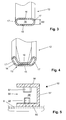
- einen Schnitt durch einen Schellenbügel entlang der Linie II-II in Fig. 1;
- Fig. 3
- einen Schnitt durch den Schellenbügel entlang der Linie III-III in Fig. 1;
- Fig. 4
- einen Schnitt durch den Schellenbügel entlang der Linie IV-IV in Fig. 1; und
- Fig. 5
- einen Schnitt durch einen Schellenbügel eines zweiten Ausführungsbeispiels analog Fig. 2.
- Grundsätzlich sind in den Figuren gleiche Teile mit den gleichen Bezugszeichen versehen.
- Die in den Figuren 1 bis 4 dargestellte Rohrschelle 11 weist zwei Schellenbügel 12 und 22 auf. Der Schellenbügel 12 weist eine Krümmung in Form eines annähernd halbkreisförmig gebogenen Abschnitts, einen ersten, krümmungsseitig innenliegenden Wandabschnitt 15, einen dem ersten Wandabschnitt 15 gegenüberliegenden zweiten Wandabschnitt 16 sowie die Wandabschnitte 15 und 16 verbindende Verbindungsabschnitte 17 auf. Der erste Wandabschnitt 15 kommt im montierten Zustand der Rohrschelle mit dem zu fixierenden Rohr 6 in Anlage. Der zweite Wandabschnitt 16 ist entlang des gesamten Verlaufs des Schellenbügels 12 unter Ausbildung eines Innenhohlraums 18 in einem Abstand zu dem ersten Wandabschnitt 15 angeordnet. Der Schellenbügel 22 weist ebenfalls eine Krümmung in Form eines annähernd halbkreisförmig gebogenen Abschnitts, einen ersten, krümmungsseitig innenliegenden Wandabschnitt 25, der im montierten Zustand ebenfalls einen Anlageabschnitt zur Anlage an dem zu fixierenden Rohr 6 bildet, einen dem ersten Wandabschnitt 15 gegenüberliegenden zweiten Wandabschnitt 16, der unter Ausbildung eines Innenhohlraums 18 entlang des gesamten Verlaufs des Schellenbügels 22 in einem Abstand zu dem ersten Wandabschnitt 25 angeordnet ist, sowie die Wandabschnitte 25 und 26 verbindende Verbindungsabschnitte 27 auf.
- Beide Schellenbügel 12 und 22 sind aus einem umfänglich geschlossenen, den Innenhohlraum 18 bzw. 28 ausbildenden ursprünglich ovalen Hohlprofil als Halbfabrikat gefertigt. Der Innenhohlraum 18 bzw. 28 weist entlang des Verlaufs des Schellenbügels 12 bzw. 22 unterschiedliche Höhen H1 und H2 auf. Die Hohlprofile sind an die Anforderungen durch Umformung angepasst. Bei beiden Schellenbügel 12 und 22 ist die Höhe H1 des Innenhohlraums 18 bzw. 28 am Scheitelpunkt 14 bzw. 24 der Krümmung am grössten.
- Die Schellenbügel 12 und 22 weisen zudem radial nach aussen ragende Flansche 13 bzw. 23 als Endbereiche auf. Die Flansche 13 weisen jeweils eine Öffnung mit einem Innengewinde für Spannschrauben 7 und die Flansche 23 weisen jeweils eine Durchführöffnung für die Spannschrauben 7 auf, so dass die Schellenbügel 12 und 22 über die Flansche 13 und 23 zur Abhängung eines Rohres 6 miteinander verbindbar sind. Im Bereich der Flansche 13 und 23 liegt der zweite Wandabschnitt 16 bzw. 26 bereichsweise an dem ersten Wandabschnitt 15 an. Die im Querschnitt seitlichen Ränder 19 sind zur krümmungsseitig aussenliegenden Seite hin weggebogen, so dass die Flansche 13 und 23 in diesem Bereich einen im Wesentlichen U-förmigen Querschnitt aufweisen. In den seitlichen Rändern 19 weisen die von den Wandabschnitten 15, 16 und 17 bzw. 25, 26 und 27 geschaffenen Hohlräume 18 bzw. 28 eine grössere Erstreckung auf.
- Wie insbesondere in der Fig. 3 dargestellt, weist der Innenraum 18 des Schellenbügels 12 wie auch der Innenraum 28 des Schellenbügels 22 zwischen dem Scheitelpunkt 14 bzw. 24 und den Flanschen 13 bzw. 23 eine Höhe H2 auf, die kleiner als die Höhe H1 des Hohlprofils am Scheitelpunkt 14 bzw. 24 des gebogenen Abschnitts beziehungsweise der Krümmung des Schellenbügels 12 bzw. 22 ist. Der Querschnitt des Hohlprofils ist in diesem Bereich für eine möglichst grosse flächige Anlage des ersten, krümmungsseitig innenliegenden Wandabschnitts 15 bzw. 25 des Schellenbügels 12 bzw. 22 an dem festzulegenden Rohr 6 verformt, so dass in diesem Bereich nur geringe Flächenpressungen auf das Rohr 6 einwirken.
- Am Scheitelpunkt 14 der Krümmung des Schellenbügels 12 sind als Befestigungsmittel 36 zwei Gewindedurchzüge 37 und 38 vorgesehen. Die Gewindedurchzüge 37 und 38 liegen auf einer gemeinsamen Achse 39 und deren freie Enden 40 und 41 sind einander zugewandt. Der am zweiten, krümmungsseitig aussenliegenden Wandabschnitt 16 des Schellenbügels 12 ausgebildete Gewindedurchzug 37 weist ein M10-Innengewinde auf und ist somit grösser als der am ersten, krümmungsseitig innenliegenden Wandabschnitt 15 des Schellenbügels 12 angeordnete Gewindedurchzug 38 ausgebildet, der ein M8-Innengewinde aufweist.
- In der Fig. 5 ist ein zweites Ausführungsbeispiel eines erfindungsgemässen Schellenbügels 52 dargestellt. Der Schellenbügel 52 weist eine Krümmung, einen ersten, krümmungsseitig innenliegenden Wandabschnitt 55, einen dem ersten Wandabschnitt 55 gegenüberliegenden zweiten Wandabschnitt 56 sowie einen die Wandabschnitte 55 und 56 verbindenden Verbindungsabschnitt 57 auf. Der zweite Wandabschnitt 56 ist entlang des gesamten Verlaufs des Schellenbügels 52 unter Ausbildung eines Innenhohlraums 58 in einem Abstand zu dem ersten Wandabschnitt 55 angeordnet.
- An den Wandabschnitten 55 und 56 sind als Befestigungsmittel 66 zwei auf einer gemeinsamen Achse 69 liegende, einander zugewandte Gewindedurchzüge 67 und 68 vorgesehen, wobei der am zweiten, krümmungsseitig aussenliegenden Wandabschnitt 56 ausgebildete Gewindedurchzug 67 grösser als der am ersten, krümmungsseitig innenliegenden Wandabschnitt 55 angeordnete Gewindedurchzug 68 ausgebildet ist.
Claims (9)
- Rohrschelle mit Schellenbügeln (12, 22; 52), die an Endbereichen miteinander verbindbar sind, wobei zumindest ein Schellenbügel (12, 22; 52) eine Krümmung, einen ersten, krümmungsseitig innenliegenden Wandabschnitt (15, 25; 55), einen dem ersten Wandabschnitt (15, 25; 55) gegenüberliegenden zweiten Wandabschnitt (16, 26; 56) sowie einen die Wandabschnitte (15, 16, 25, 26; 55, 56) verbindenden Verbindungsabschnitt (17, 27; 57) aufweist, dadurch gekennzeichnet, dass der zweite Wandabschnitt (16, 26; 56) entlang des gesamten Verlaufs des Schellenbügels (12, 22; 52) unter Ausbildung eines Innenhohlraums (18, 28; 58) in einem Abstand zu dem ersten Wandabschnitt (15, 25; 55) angeordnet ist.
- Rohrschelle nach Anspruch 1, dadurch gekennzeichnet, dass zumindest ein Schellenbügel (12, 22) aus einem umfänglich geschlossenen, den Innenhohlraum (18, 28) ausbildenden Hohlprofil gefertigt ist.
- Rohrschelle nach Anspruch 1 oder 2, dadurch gekennzeichnet, dass der Innenhohlraum (18, 28) entlang des Verlaufs des Schellenbügels (12, 22) unterschiedliche Höhen (H1, H2) aufweist.
- Rohrschelle nach einem der Ansprüche 1 bis 3, dadurch gekennzeichnet, dass die Höhe (H1) des Innenhohlraums (18, 28) am Scheitelpunkt (14, 24) der Krümmung am grössten ist.
- Rohrschelle nach einem der Ansprüche 1 bis 4, dadurch gekennzeichnet, dass zumindest ein Schellenbügel (12, 22) nach aussen ragende Flansche (13, 23) aufweist.
- Rohrschelle nach einem der Ansprüche 1 bis 5, dadurch gekennzeichnet, dass ein Befestigungsmittel (36; 66) an zumindest einem der Schellenbügel (12; 52) vorgesehen ist.
- Rohrschelle nach Anspruch 6, dadurch gekennzeichnet, dass das Befestigungsmittel (36) am Scheitelpunkt (14) einer Krümmung des Schellenbügels (12) vorgesehen ist.
- Rohrschelle nach Anspruch 6 oder 7, dadurch gekennzeichnet, dass das Befestigungsmittel (36; 66) ein Gewindedurchzug (37, 38; 67, 68) ist.
- Rohrschelle nach Anspruch 8, dadurch gekennzeichnet, dass das Befestigungsmittel (36; 66) zwei Gewindedurchzüge (37, 38; 67, 68) umfasst, die an den zwei einander gegenüberliegenden Wandabschnitten (15, 16; 55, 56) ausgebildet sind und auf einer gemeinsamen Achse (39,69) liegen, wobei der eine Gewindedurchzug (37; 67) einen grösseren Innendurchmesser als der andere Gewindedurchzug (38; 68) aufweist.
Applications Claiming Priority (1)
| Application Number | Priority Date | Filing Date | Title |
|---|---|---|---|
| DE200610035368 DE102006035368A1 (de) | 2006-10-23 | 2006-10-23 | Rohrschelle |
Publications (3)
| Publication Number | Publication Date |
|---|---|
| EP1916463A2 true EP1916463A2 (de) | 2008-04-30 |
| EP1916463A3 EP1916463A3 (de) | 2013-03-06 |
| EP1916463B1 EP1916463B1 (de) | 2014-04-30 |
Family
ID=38924385
Family Applications (1)
| Application Number | Title | Priority Date | Filing Date |
|---|---|---|---|
| EP20070118262 Not-in-force EP1916463B1 (de) | 2006-10-23 | 2007-10-11 | Rohrschelle |
Country Status (2)
| Country | Link |
|---|---|
| EP (1) | EP1916463B1 (de) |
| DE (1) | DE102006035368A1 (de) |
Cited By (1)
| Publication number | Priority date | Publication date | Assignee | Title |
|---|---|---|---|---|
| CN107013748A (zh) * | 2017-05-31 | 2017-08-04 | 贵州航太精密制造有限公司 | 一种具有自锁功能的卡箍 |
Family Cites Families (3)
| Publication number | Priority date | Publication date | Assignee | Title |
|---|---|---|---|---|
| US3594706A (en) * | 1969-05-21 | 1971-07-20 | Thomas & Betts Corp | Ground connector |
| DE3661770D1 (en) * | 1985-02-23 | 1989-02-16 | Kurt Allert | Pipe clamp |
| DE9206705U1 (de) * | 1992-05-16 | 1993-09-16 | Halfen GmbH & Co. KG, 40591 Düsseldorf | Rohrschelle |
-
2006
- 2006-10-23 DE DE200610035368 patent/DE102006035368A1/de not_active Withdrawn
-
2007
- 2007-10-11 EP EP20070118262 patent/EP1916463B1/de not_active Not-in-force
Cited By (1)
| Publication number | Priority date | Publication date | Assignee | Title |
|---|---|---|---|---|
| CN107013748A (zh) * | 2017-05-31 | 2017-08-04 | 贵州航太精密制造有限公司 | 一种具有自锁功能的卡箍 |
Also Published As
| Publication number | Publication date |
|---|---|
| EP1916463A3 (de) | 2013-03-06 |
| EP1916463B1 (de) | 2014-04-30 |
| DE102006035368A1 (de) | 2008-04-24 |
Similar Documents
| Publication | Publication Date | Title |
|---|---|---|
| DE19534437C2 (de) | Schelle zur Verbindung von zwei rohrförmigen Leitungsteilen | |
| DE102006034463B3 (de) | Vorrichtung zum Befestigen eines Anbauteiles und eines Trägerteiles in einem Abstand voneinander | |
| EP1997976B1 (de) | Profilschiene | |
| EP2481939B1 (de) | Spannschelle | |
| EP1447576B1 (de) | Kunststoffmutter zur Aufnahme an einem einen Durchbruch aufweisenden Bauteil | |
| DE102004003240A1 (de) | Blindnietmutter | |
| DE2025416A1 (de) | Rohrkupplung | |
| DE8435313U1 (de) | Rohrverbindung | |
| EP1404987A1 (de) | Gummilager, vorzugsweise stabilisatorlager, und verfahren zur montage des lagers | |
| DE19542463B4 (de) | Rohrkupplung | |
| EP3105483B1 (de) | Schelle | |
| DE102005000129A1 (de) | Befestigungsvorrichtung für die Befestigung von Solarpaneelen an einer Montageschiene | |
| EP1950480B1 (de) | Rohrschelle | |
| DE3346423A1 (de) | Rohrschelle | |
| EP1950479B1 (de) | Rohrschelle | |
| EP2872808B1 (de) | Rohrschelle | |
| DE102011116948B3 (de) | Bandschelle | |
| EP2812619B1 (de) | Rohrkupplung | |
| EP1916463B1 (de) | Rohrschelle | |
| EP3379091B1 (de) | Befestigungsvorrichtung für ein spannband | |
| CH640622A5 (en) | Attachment device for pipes or similar objects | |
| DE3509310A1 (de) | Schwenkrohrauslauf fuer armaturen | |
| DE69925404T2 (de) | Metallische Verbindungsvorrichtung und Beschlagteile dafür | |
| DE102006017224A1 (de) | Vorrichtung zur Befestigung eines Stabilisators an einem Kraftfahrzeugaufbau | |
| DE20102930U1 (de) | Schelle |
Legal Events
| Date | Code | Title | Description |
|---|---|---|---|
| PUAI | Public reference made under article 153(3) epc to a published international application that has entered the european phase |
Free format text: ORIGINAL CODE: 0009012 |
|
| AK | Designated contracting states |
Kind code of ref document: A2 Designated state(s): AT BE BG CH CY CZ DE DK EE ES FI FR GB GR HU IE IS IT LI LT LU LV MC MT NL PL PT RO SE SI SK TR |
|
| AX | Request for extension of the european patent |
Extension state: AL BA HR MK RS |
|
| PUAL | Search report despatched |
Free format text: ORIGINAL CODE: 0009013 |
|
| AK | Designated contracting states |
Kind code of ref document: A3 Designated state(s): AT BE BG CH CY CZ DE DK EE ES FI FR GB GR HU IE IS IT LI LT LU LV MC MT NL PL PT RO SE SI SK TR |
|
| AX | Request for extension of the european patent |
Extension state: AL BA HR MK RS |
|
| RIC1 | Information provided on ipc code assigned before grant |
Ipc: F16L 3/10 20060101AFI20130130BHEP |
|
| 17P | Request for examination filed |
Effective date: 20130906 |
|
| RBV | Designated contracting states (corrected) |
Designated state(s): AT BE BG CH CY CZ DE DK EE ES FI FR GB GR HU IE IS IT LI LT LU LV MC MT NL PL PT RO SE SI SK TR |
|
| AKX | Designation fees paid |
Designated state(s): AT BE BG CH CY CZ DE DK EE ES FI FR GB GR HU IE IS IT LI LT LU LV MC MT NL PL PT RO SE SI SK TR |
|
| GRAP | Despatch of communication of intention to grant a patent |
Free format text: ORIGINAL CODE: EPIDOSNIGR1 |
|
| INTG | Intention to grant announced |
Effective date: 20131220 |
|
| GRAS | Grant fee paid |
Free format text: ORIGINAL CODE: EPIDOSNIGR3 |
|
| GRAA | (expected) grant |
Free format text: ORIGINAL CODE: 0009210 |
|
| AK | Designated contracting states |
Kind code of ref document: B1 Designated state(s): AT BE BG CH CY CZ DE DK EE ES FI FR GB GR HU IE IS IT LI LT LU LV MC MT NL PL PT RO SE SI SK TR |
|
| REG | Reference to a national code |
Ref country code: GB Ref legal event code: FG4D Free format text: NOT ENGLISH Ref country code: CH Ref legal event code: EP |
|
| REG | Reference to a national code |
Ref country code: AT Ref legal event code: REF Ref document number: 665374 Country of ref document: AT Kind code of ref document: T Effective date: 20140515 |
|
| REG | Reference to a national code |
Ref country code: IE Ref legal event code: FG4D Free format text: LANGUAGE OF EP DOCUMENT: GERMAN |
|
| REG | Reference to a national code |
Ref country code: DE Ref legal event code: R096 Ref document number: 502007013039 Country of ref document: DE Effective date: 20140612 |
|
| REG | Reference to a national code |
Ref country code: LT Ref legal event code: MG4D |
|
| REG | Reference to a national code |
Ref country code: NL Ref legal event code: VDEP Effective date: 20140430 |
|
| PG25 | Lapsed in a contracting state [announced via postgrant information from national office to epo] |
Ref country code: LT Free format text: LAPSE BECAUSE OF FAILURE TO SUBMIT A TRANSLATION OF THE DESCRIPTION OR TO PAY THE FEE WITHIN THE PRESCRIBED TIME-LIMIT Effective date: 20140430 Ref country code: BG Free format text: LAPSE BECAUSE OF FAILURE TO SUBMIT A TRANSLATION OF THE DESCRIPTION OR TO PAY THE FEE WITHIN THE PRESCRIBED TIME-LIMIT Effective date: 20140730 Ref country code: IS Free format text: LAPSE BECAUSE OF FAILURE TO SUBMIT A TRANSLATION OF THE DESCRIPTION OR TO PAY THE FEE WITHIN THE PRESCRIBED TIME-LIMIT Effective date: 20140830 Ref country code: FI Free format text: LAPSE BECAUSE OF FAILURE TO SUBMIT A TRANSLATION OF THE DESCRIPTION OR TO PAY THE FEE WITHIN THE PRESCRIBED TIME-LIMIT Effective date: 20140430 Ref country code: NL Free format text: LAPSE BECAUSE OF FAILURE TO SUBMIT A TRANSLATION OF THE DESCRIPTION OR TO PAY THE FEE WITHIN THE PRESCRIBED TIME-LIMIT Effective date: 20140430 Ref country code: CY Free format text: LAPSE BECAUSE OF FAILURE TO SUBMIT A TRANSLATION OF THE DESCRIPTION OR TO PAY THE FEE WITHIN THE PRESCRIBED TIME-LIMIT Effective date: 20140430 |
|
| PG25 | Lapsed in a contracting state [announced via postgrant information from national office to epo] |
Ref country code: ES Free format text: LAPSE BECAUSE OF FAILURE TO SUBMIT A TRANSLATION OF THE DESCRIPTION OR TO PAY THE FEE WITHIN THE PRESCRIBED TIME-LIMIT Effective date: 20140430 Ref country code: PL Free format text: LAPSE BECAUSE OF FAILURE TO SUBMIT A TRANSLATION OF THE DESCRIPTION OR TO PAY THE FEE WITHIN THE PRESCRIBED TIME-LIMIT Effective date: 20140430 Ref country code: SE Free format text: LAPSE BECAUSE OF FAILURE TO SUBMIT A TRANSLATION OF THE DESCRIPTION OR TO PAY THE FEE WITHIN THE PRESCRIBED TIME-LIMIT Effective date: 20140430 Ref country code: LV Free format text: LAPSE BECAUSE OF FAILURE TO SUBMIT A TRANSLATION OF THE DESCRIPTION OR TO PAY THE FEE WITHIN THE PRESCRIBED TIME-LIMIT Effective date: 20140430 |
|
| PG25 | Lapsed in a contracting state [announced via postgrant information from national office to epo] |
Ref country code: PT Free format text: LAPSE BECAUSE OF FAILURE TO SUBMIT A TRANSLATION OF THE DESCRIPTION OR TO PAY THE FEE WITHIN THE PRESCRIBED TIME-LIMIT Effective date: 20140901 |
|
| PG25 | Lapsed in a contracting state [announced via postgrant information from national office to epo] |
Ref country code: RO Free format text: LAPSE BECAUSE OF FAILURE TO SUBMIT A TRANSLATION OF THE DESCRIPTION OR TO PAY THE FEE WITHIN THE PRESCRIBED TIME-LIMIT Effective date: 20140430 Ref country code: DK Free format text: LAPSE BECAUSE OF FAILURE TO SUBMIT A TRANSLATION OF THE DESCRIPTION OR TO PAY THE FEE WITHIN THE PRESCRIBED TIME-LIMIT Effective date: 20140430 Ref country code: CZ Free format text: LAPSE BECAUSE OF FAILURE TO SUBMIT A TRANSLATION OF THE DESCRIPTION OR TO PAY THE FEE WITHIN THE PRESCRIBED TIME-LIMIT Effective date: 20140430 Ref country code: EE Free format text: LAPSE BECAUSE OF FAILURE TO SUBMIT A TRANSLATION OF THE DESCRIPTION OR TO PAY THE FEE WITHIN THE PRESCRIBED TIME-LIMIT Effective date: 20140430 Ref country code: SK Free format text: LAPSE BECAUSE OF FAILURE TO SUBMIT A TRANSLATION OF THE DESCRIPTION OR TO PAY THE FEE WITHIN THE PRESCRIBED TIME-LIMIT Effective date: 20140430 |
|
| REG | Reference to a national code |
Ref country code: DE Ref legal event code: R097 Ref document number: 502007013039 Country of ref document: DE |
|
| PLBE | No opposition filed within time limit |
Free format text: ORIGINAL CODE: 0009261 |
|
| STAA | Information on the status of an ep patent application or granted ep patent |
Free format text: STATUS: NO OPPOSITION FILED WITHIN TIME LIMIT |
|
| PG25 | Lapsed in a contracting state [announced via postgrant information from national office to epo] |
Ref country code: IT Free format text: LAPSE BECAUSE OF FAILURE TO SUBMIT A TRANSLATION OF THE DESCRIPTION OR TO PAY THE FEE WITHIN THE PRESCRIBED TIME-LIMIT Effective date: 20140430 |
|
| 26N | No opposition filed |
Effective date: 20150202 |
|
| REG | Reference to a national code |
Ref country code: DE Ref legal event code: R119 Ref document number: 502007013039 Country of ref document: DE |
|
| REG | Reference to a national code |
Ref country code: DE Ref legal event code: R097 Ref document number: 502007013039 Country of ref document: DE Effective date: 20150202 |
|
| PG25 | Lapsed in a contracting state [announced via postgrant information from national office to epo] |
Ref country code: MC Free format text: LAPSE BECAUSE OF FAILURE TO SUBMIT A TRANSLATION OF THE DESCRIPTION OR TO PAY THE FEE WITHIN THE PRESCRIBED TIME-LIMIT Effective date: 20140430 Ref country code: LU Free format text: LAPSE BECAUSE OF FAILURE TO SUBMIT A TRANSLATION OF THE DESCRIPTION OR TO PAY THE FEE WITHIN THE PRESCRIBED TIME-LIMIT Effective date: 20141011 |
|
| REG | Reference to a national code |
Ref country code: CH Ref legal event code: PL |
|
| GBPC | Gb: european patent ceased through non-payment of renewal fee |
Effective date: 20141011 |
|
| PG25 | Lapsed in a contracting state [announced via postgrant information from national office to epo] |
Ref country code: BE Free format text: LAPSE BECAUSE OF NON-PAYMENT OF DUE FEES Effective date: 20141031 |
|
| REG | Reference to a national code |
Ref country code: IE Ref legal event code: MM4A |
|
| PG25 | Lapsed in a contracting state [announced via postgrant information from national office to epo] |
Ref country code: LI Free format text: LAPSE BECAUSE OF NON-PAYMENT OF DUE FEES Effective date: 20141031 Ref country code: GB Free format text: LAPSE BECAUSE OF NON-PAYMENT OF DUE FEES Effective date: 20141011 Ref country code: CH Free format text: LAPSE BECAUSE OF NON-PAYMENT OF DUE FEES Effective date: 20141031 Ref country code: DE Free format text: LAPSE BECAUSE OF NON-PAYMENT OF DUE FEES Effective date: 20150501 Ref country code: SI Free format text: LAPSE BECAUSE OF FAILURE TO SUBMIT A TRANSLATION OF THE DESCRIPTION OR TO PAY THE FEE WITHIN THE PRESCRIBED TIME-LIMIT Effective date: 20140430 |
|
| REG | Reference to a national code |
Ref country code: FR Ref legal event code: ST Effective date: 20150630 |
|
| PG25 | Lapsed in a contracting state [announced via postgrant information from national office to epo] |
Ref country code: FR Free format text: LAPSE BECAUSE OF NON-PAYMENT OF DUE FEES Effective date: 20141031 |
|
| PG25 | Lapsed in a contracting state [announced via postgrant information from national office to epo] |
Ref country code: IE Free format text: LAPSE BECAUSE OF NON-PAYMENT OF DUE FEES Effective date: 20141011 |
|
| REG | Reference to a national code |
Ref country code: AT Ref legal event code: MM01 Ref document number: 665374 Country of ref document: AT Kind code of ref document: T Effective date: 20141011 |
|
| PG25 | Lapsed in a contracting state [announced via postgrant information from national office to epo] |
Ref country code: AT Free format text: LAPSE BECAUSE OF NON-PAYMENT OF DUE FEES Effective date: 20141011 |
|
| PG25 | Lapsed in a contracting state [announced via postgrant information from national office to epo] |
Ref country code: GR Free format text: LAPSE BECAUSE OF FAILURE TO SUBMIT A TRANSLATION OF THE DESCRIPTION OR TO PAY THE FEE WITHIN THE PRESCRIBED TIME-LIMIT Effective date: 20140430 |
|
| PG25 | Lapsed in a contracting state [announced via postgrant information from national office to epo] |
Ref country code: TR Free format text: LAPSE BECAUSE OF FAILURE TO SUBMIT A TRANSLATION OF THE DESCRIPTION OR TO PAY THE FEE WITHIN THE PRESCRIBED TIME-LIMIT Effective date: 20140430 Ref country code: HU Free format text: LAPSE BECAUSE OF FAILURE TO SUBMIT A TRANSLATION OF THE DESCRIPTION OR TO PAY THE FEE WITHIN THE PRESCRIBED TIME-LIMIT; INVALID AB INITIO Effective date: 20071011 Ref country code: MT Free format text: LAPSE BECAUSE OF FAILURE TO SUBMIT A TRANSLATION OF THE DESCRIPTION OR TO PAY THE FEE WITHIN THE PRESCRIBED TIME-LIMIT Effective date: 20140430 |