EP1916099B1 - Beschichtungsanordnung - Google Patents
Beschichtungsanordnung Download PDFInfo
- Publication number
- EP1916099B1 EP1916099B1 EP07019741.3A EP07019741A EP1916099B1 EP 1916099 B1 EP1916099 B1 EP 1916099B1 EP 07019741 A EP07019741 A EP 07019741A EP 1916099 B1 EP1916099 B1 EP 1916099B1
- Authority
- EP
- European Patent Office
- Prior art keywords
- slits
- roller
- midpoint
- rollers
- spaced
- Prior art date
- Legal status (The legal status is an assumption and is not a legal conclusion. Google has not performed a legal analysis and makes no representation as to the accuracy of the status listed.)
- Not-in-force
Links
- 238000010030 laminating Methods 0.000 claims description 49
- 238000010438 heat treatment Methods 0.000 claims description 23
- 238000003475 lamination Methods 0.000 claims description 16
- 238000007906 compression Methods 0.000 claims description 15
- 230000006835 compression Effects 0.000 claims description 14
- 238000013022 venting Methods 0.000 claims description 5
- 239000000463 material Substances 0.000 description 12
- 239000000853 adhesive Substances 0.000 description 9
- 230000001070 adhesive effect Effects 0.000 description 9
- 238000003780 insertion Methods 0.000 description 4
- 230000037431 insertion Effects 0.000 description 4
- 238000002844 melting Methods 0.000 description 3
- 230000008018 melting Effects 0.000 description 3
- 239000004840 adhesive resin Substances 0.000 description 2
- 229920006223 adhesive resin Polymers 0.000 description 2
- 230000000712 assembly Effects 0.000 description 2
- 238000000429 assembly Methods 0.000 description 2
- 230000000694 effects Effects 0.000 description 2
- 230000007246 mechanism Effects 0.000 description 2
- 238000000034 method Methods 0.000 description 2
- 230000003090 exacerbative effect Effects 0.000 description 1
- 238000011065 in-situ storage Methods 0.000 description 1
Images


Classifications
-
- B—PERFORMING OPERATIONS; TRANSPORTING
- B32—LAYERED PRODUCTS
- B32B—LAYERED PRODUCTS, i.e. PRODUCTS BUILT-UP OF STRATA OF FLAT OR NON-FLAT, e.g. CELLULAR OR HONEYCOMB, FORM
- B32B37/00—Methods or apparatus for laminating, e.g. by curing or by ultrasonic bonding
- B32B37/0046—Methods or apparatus for laminating, e.g. by curing or by ultrasonic bonding characterised by constructional aspects of the apparatus
- B32B37/0053—Constructional details of laminating machines comprising rollers; Constructional features of the rollers
-
- B—PERFORMING OPERATIONS; TRANSPORTING
- B32—LAYERED PRODUCTS
- B32B—LAYERED PRODUCTS, i.e. PRODUCTS BUILT-UP OF STRATA OF FLAT OR NON-FLAT, e.g. CELLULAR OR HONEYCOMB, FORM
- B32B37/00—Methods or apparatus for laminating, e.g. by curing or by ultrasonic bonding
- B32B37/0046—Methods or apparatus for laminating, e.g. by curing or by ultrasonic bonding characterised by constructional aspects of the apparatus
-
- B—PERFORMING OPERATIONS; TRANSPORTING
- B32—LAYERED PRODUCTS
- B32B—LAYERED PRODUCTS, i.e. PRODUCTS BUILT-UP OF STRATA OF FLAT OR NON-FLAT, e.g. CELLULAR OR HONEYCOMB, FORM
- B32B37/00—Methods or apparatus for laminating, e.g. by curing or by ultrasonic bonding
- B32B37/14—Methods or apparatus for laminating, e.g. by curing or by ultrasonic bonding characterised by the properties of the layers
- B32B37/16—Methods or apparatus for laminating, e.g. by curing or by ultrasonic bonding characterised by the properties of the layers with all layers existing as coherent layers before laminating
- B32B37/18—Methods or apparatus for laminating, e.g. by curing or by ultrasonic bonding characterised by the properties of the layers with all layers existing as coherent layers before laminating involving the assembly of discrete sheets or panels only
- B32B37/182—Methods or apparatus for laminating, e.g. by curing or by ultrasonic bonding characterised by the properties of the layers with all layers existing as coherent layers before laminating involving the assembly of discrete sheets or panels only one or more of the layers being plastic
- B32B37/185—Laminating sheets, panels or inserts between two discrete plastic layers
-
- B—PERFORMING OPERATIONS; TRANSPORTING
- B32—LAYERED PRODUCTS
- B32B—LAYERED PRODUCTS, i.e. PRODUCTS BUILT-UP OF STRATA OF FLAT OR NON-FLAT, e.g. CELLULAR OR HONEYCOMB, FORM
- B32B2439/00—Containers; Receptacles
-
- B—PERFORMING OPERATIONS; TRANSPORTING
- B32—LAYERED PRODUCTS
- B32B—LAYERED PRODUCTS, i.e. PRODUCTS BUILT-UP OF STRATA OF FLAT OR NON-FLAT, e.g. CELLULAR OR HONEYCOMB, FORM
- B32B37/00—Methods or apparatus for laminating, e.g. by curing or by ultrasonic bonding
- B32B37/0007—Methods or apparatus for laminating, e.g. by curing or by ultrasonic bonding involving treatment or provisions in order to avoid deformation or air inclusion, e.g. to improve surface quality
- B32B37/0015—Methods or apparatus for laminating, e.g. by curing or by ultrasonic bonding involving treatment or provisions in order to avoid deformation or air inclusion, e.g. to improve surface quality to avoid warp or curl
-
- B—PERFORMING OPERATIONS; TRANSPORTING
- B32—LAYERED PRODUCTS
- B32B—LAYERED PRODUCTS, i.e. PRODUCTS BUILT-UP OF STRATA OF FLAT OR NON-FLAT, e.g. CELLULAR OR HONEYCOMB, FORM
- B32B37/00—Methods or apparatus for laminating, e.g. by curing or by ultrasonic bonding
- B32B37/08—Methods or apparatus for laminating, e.g. by curing or by ultrasonic bonding characterised by the cooling method
-
- Y—GENERAL TAGGING OF NEW TECHNOLOGICAL DEVELOPMENTS; GENERAL TAGGING OF CROSS-SECTIONAL TECHNOLOGIES SPANNING OVER SEVERAL SECTIONS OF THE IPC; TECHNICAL SUBJECTS COVERED BY FORMER USPC CROSS-REFERENCE ART COLLECTIONS [XRACs] AND DIGESTS
- Y10—TECHNICAL SUBJECTS COVERED BY FORMER USPC
- Y10T—TECHNICAL SUBJECTS COVERED BY FORMER US CLASSIFICATION
- Y10T156/00—Adhesive bonding and miscellaneous chemical manufacture
- Y10T156/12—Surface bonding means and/or assembly means with cutting, punching, piercing, severing or tearing
- Y10T156/1378—Cutter actuated by or secured to bonding element
-
- Y—GENERAL TAGGING OF NEW TECHNOLOGICAL DEVELOPMENTS; GENERAL TAGGING OF CROSS-SECTIONAL TECHNOLOGIES SPANNING OVER SEVERAL SECTIONS OF THE IPC; TECHNICAL SUBJECTS COVERED BY FORMER USPC CROSS-REFERENCE ART COLLECTIONS [XRACs] AND DIGESTS
- Y10—TECHNICAL SUBJECTS COVERED BY FORMER USPC
- Y10T—TECHNICAL SUBJECTS COVERED BY FORMER US CLASSIFICATION
- Y10T156/00—Adhesive bonding and miscellaneous chemical manufacture
- Y10T156/17—Surface bonding means and/or assemblymeans with work feeding or handling means
- Y10T156/1702—For plural parts or plural areas of single part
- Y10T156/1712—Indefinite or running length work
- Y10T156/1741—Progressive continuous bonding press [e.g., roll couples]
Definitions
- the present invention relates to a laminator assembly for use in a laminator.
- Laminators are well known and, generally speaking, are used to bond an outer layer of laminating material to a substantially flat sheet of material to form a laminate.
- the laminating material which has an adhesive backing, is typically provided in the form of a pouch or envelope into which the sheet material may be placed prior to insertion into a laminator; alternatively the laminating material may simply be provided in the form of a sheet or film which is laid over the sheet material to form a multi-layer sandwich prior to insertion into the laminator.
- the laminating pouch or sandwich is fed between a pair of rollers which act to compress the lamination pouch or sandwich, thereby bonding the laminating material sheet to the flat sheet of material.
- the resulting laminate exits from between the rollers and is guided away from the rollers between a pair of exit plates associated with the rollers.
- the laminating material may generally be provided with a heat-curable adhesive resin backing, and the laminator further comprises a heat source, typically located in the region of the rollers, for melting the adhesive as the laminating pouch or sandwich is compressed between the "hot rollers", the adhesive hardening as it cools to fixedly bond the laminating material to the sheet of material.
- a heat source typically located in the region of the rollers
- a typical "four-roller" laminator is similar to a "two-roller” laminator but, in addition to a first pair of rollers, the laminator further comprises a second pair of rollers positioned "downstream" of the first pair of rollers. In this manner, the laminating pouch or sandwich is fed between both pairs of rollers and is therefore subject to a two-stage compression process.
- Each pair of rollers in a "four-roller” laminator can conveniently be thought of as corresponding to a “two-roller” assembly similar to that found in a "two-roller” laminator.
- each of the two pairs of rollers has an associated pair of exit plates for guiding the laminating pouch away from the respective rollers.
- the laminating material may again be provided with a heat curable adhesive resin backing, and the laminator further comprises one or more heat sources, typically located in the region of one or more of the pairs of rollers, for melting the adhesive as the laminating pouch or sandwich is compressed between the respective rollers.
- JP-U-04054831 discloses a card lamination device characterised in that it consists of the following positioned in the card-input line: a card insertion section; a pair of counter-rotating card pressure-seal rollers positioned one above the other; and a heating device between the said insertion section and the said card pressure-seal rollers.
- the said device is also characterised in that flange-shaped guides are positioned on the output side of the said card pressure-seal rollers, in such a manner as to come into contact with the roller rotating surfaces.
- Roller jams occur when the laminating pouch or sandwich becomes adhered to one of the rollers, for example due to excessive residual adhesive on the roller from prior use, or due to adhesive in the pouch or sandwich being squeezed onto the rollers during operation of the laminator. Rather than exiting from between the rollers, the laminating pouch or sandwich remains stuck to the outer surface of the respective roller, where it may cause a blockage within the laminator or otherwise interfere with the operation of the laminator.
- Exit plate jams may occur in laminators during hot lamination.
- the laminating pouch or sandwich properly exits from between the rollers as the final laminate, but, due to the high temperatures in the proximity of the rollers and exit plates, curling or wrinkling of the laminate occurs after it has exited from between the rollers. If a sufficient degree of curling or wrinkling occurs, the laminate may again cause a blockage, particularly in the region of the exit plates, with any slight contact of the laminate with the exit plates greatly accentuating the curling effect and exacerbating the problem.
- Jams within laminators can be difficult to rectify, due in part to the fact that, even if the laminating pouch or sandwich can be easily removed from within the laminator, residual adhesive may nevertheless still be difficult to remove from various components within the laminator. Indeed, once a jam has occurred within a laminator, it is often that case that the laminator must be stripped down and reconditioned to restore operating efficiency.
- a laminator assembly comprising a pair of rollers, the rollers defining a compression zone therebetween for compressing a substantially flat lamination pouch as the pouch is fed between the rollers and advanced through the compression zone for exit on the exit side of the rollers, a heat source being provided for heating the lamination pouch as the lamination pouch is compressed between the rollers, the laminator assembly further comprising two sets of blade members having concave cleaving surfaces positioned on the exit side of the rollers and spaced from the compression-plane of the rollers, each set of blade members being arranged axially along a respective roller and in close proximity to the exterior surface of the respective roller for cleaving the lamination pouch from the respective roller to prevent the lamination pouch from passing between the roller and respective blade members.
- the exterior surface of one or both rollers incorporates a series of circumferential slits corresponding to the respective set of blade members, each one of said blade members extending into a respective slit in the roller.
- the width of one or more of the circumferential slits is 0.1 to 0.45mm.
- the depth of one or more of the circumferential slits is 1mm to 4mm.
- one or both of the rollers has four of said circumferential slits and the respective set of blade members comprises four blade members.
- one or both of the rollers has five of said circumferential slits and the respective set of blade members comprises five blade members.
- the bottom roller has five of said circumferential slits and the top roller has four of said circumferential slits.
- the slits are spaced apart from one another along the longitudinal axis of the respective roller, symmetrically about the mid-point of the respective longitudinal axis.
- each of the rollers comprises an inner pair of circumferential slits spaced symmetrically either side of the mid point of the respective roller, and an outer pair of circumferential slits spaced symmetrically either side of the inner pair of slits, the roller with five circumferential slits further comprising a slit positioned at the mid point of the roller.
- the outer pair of slits on each roller having four circumferential slits are positioned for allowing one of either an A4-sized laminating pouch or A3-sized laminating pouch to be initially aligned with the rollers such that the outer pair of slits are spaced inwardly from the outer edge of the laminating pouch a distance 9mm to 11mm, preferably 10mm.
- the outer pair of slits on each roller having five circumferential slits are positioned for allowing one of either an A4-sized laminating pouch or A3-sized laminating pouch to be initially aligned with the rollers such that the outer pair of slits are spaced inwardly from the outer edges of the laminating pouch a distance 14mm to 16mm, preferably 15mm.
- each roller incorporating four circumferential slits is 245mm to 250mm long, with the inner pair of slits being spaced either side of said mid point at a distance 30mm to 40mm from said mid point, and the outer pair of slits being spaced either side of said mid point at a distance 90mm to 100mm from said mid point.
- the roller is between 247mm and 248mm long, the inner pair of circumferential slits being spaced either side of the mid point at a distance 31mm to 33mm from the mid point, and the outer pair of circumferential slits being spaced either side of said mid point at a distance 94mm to 96mm from said mid point.
- each roller incorporating five circumferential slits is 235mm to 250mm long, with the inner pair of circumferential slits being spaced either side of the mid point at a distance 40mm to 50mm from the mid point, and the outer pair of circumferential slits being spaced either side of the mid point at a distance 855mm to 95mm from the mid point.
- the roller comprising five circumferential slits is between 247mm and 248mm long, the inner pair of circumferential slits being spaced either side of the mid point at a distance 44mm to 46mm from the mid point, and the outer pair of circumferential slits being spaced either side of said of mid point at a distance 89mm to 91 mm from the mid point.
- each roller incorporating four circumferential slits is between 330mm and 335mm long, preferably 333.5mm long, with the inner pair of slits being spaced either side of the mid point at a distance 55mm to 65mm from the mid point, preferably 60mm from the mid point, and the outer pair of slits being spaced either side of the mid point a distance 135mm to 145mm from the mid point, preferably 138.5mm from the mid point.
- each roller incorporating five circumferential slits is between 330mm and 335mm long, preferably 333.5mm long, with the inner pair of slits being spaced either side of the mid point at a distance 60mm to 70mm from the mid point, preferably 65mm from the mid point, and the outer pair of slits being spaced either side of the mid point a distance 130mm to 140mm from the mid point, preferably 135mm from the mid point.
- each set of blade members are vertically offset from the feed-plane by a distance in the range 1.8mm to 1.3mm, measured parallel to the compression plane.
- one or both sets of blade members is mounted to an element fixed with respect to the axis of rotation of the respective roller.
- the laminator assembly incorporates a roller support assembly supporting each roller for rotation with respect to the assembly, one or both sets of blade members being fixedly mounted to the roller support assembly.
- the roller support assembly includes a heating shoe surrounding one or both rollers, one or both sets of blade members being fixedly attached to the respective heating shoe.
- the individual blade members are separate from one another.
- the laminator assembly comprises a pair of exit guide plates on the exit side of the rollers, the guide plates incorporating one or more venting apertures.
- Figures 1 to 6 illustrate only the principal components of a laminator assembly, these being the components necessary for understanding the present invention; however, it is to be appreciated that, in practice, the laminator assembly will form part of a laminator incorporating additional, conventional components such as, for example, drive mechanisms, control electronics and external and internal housings where appropriate. Detailed discussion of these conventional components is not required for an understanding of the present invention and, except where otherwise specifically mentioned in the following description, it is to be assumed that these components may be utilised in conventional manner in conjunction with the laminator assembly according to the present invention.
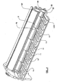
- Figure 1 shows the principal components of a laminator assembly according to a first embodiment of the present invention.
- Laminator assembly 1 comprises a generally cylindrical, rotatable upper roller 2a and a generally cylindrical, rotatable lower roller 2b arranged directly beneath and generally parallel with the upper roller 2a to define a small gap 2c between the rollers, the rollers 2a,2b thus being arranged for compressing a laminating pouch 3 as it is fed between the rollers 2a,2b via a pair of entry guide plates 4a, 4b.
- the rollers may be driven using a conventional motor (not shown) in conventional manner, and the laminator may be provided with any suitable conventional feed mechanisms for feeding the laminating pouch 3 through the rollers 2a, 2b as appropriate.
- the rollers 2a, 2b can together be considered to define a "compression-plane" C, being the plane including the axes of rotation A, B of the rollers 2a, 2b (extending out of the page in Figure 1 ).
- the rollers 2a,2b in turn also define a "feed-plane" D, being the plane orthogonal to the compression plane C and extending through the gap 2c, equidistant from each of the rollers 2a, 2b.
- the laminating pouch 3 is advanced through the rollers generally parallel to the feed-plane D, whilst compression of the laminating pouch by the rollers 2a, 2b occurs substantially parallel to the compression-plane C within a compression zone between the rollers.
- the laminating assembly 1 is provided with a heat source in the form of a pair of heating shoes 5a, 5b surrounding the respective rollers 2a, 2b. In this manner, the rollers 2a, 2b are heated and, on contact with the lamination pouch 3, act to melt the adhesive within the laminating pouch 3.
- a pair of exit guide plates 6a, 6b are located on the exit side of the rollers (the side to the right of the compression plane C in Figure 1 ) for guiding the resulting laminate (not shown) away from the rollers 2a,2b, where it may subsequently be removed from the laminating assembly 1.
- each of the exit guide plates 6a, 6b are provided with a respective set of blade members 7a, 7b incorporating concave cleaving surfaces 7c, 7d.
- the set of blade members 7a incorporates four blade members, whilst the set of blade members 7b incorporates five blade members.
- Each set of blade members 7a, 7b is positioned on the exit side of the rollers and spaced from the compression-plane of the rollers 2a, 2b.
- the blade members 7a, 7b are arranged axially along the respective roller 6a, 6b and are arranged such that they extend into corresponding circumferential slits 8 provided on the external surface of the rollers 2a, 2b.
- the blade members are arranged in close proximity to the exterior surface of the rollers 2a, 2b, and more specifically actually extend into the rollers 2a, 2b.
- the laminating pouch 3 As the laminating pouch 3 is carried by the roller 2a or 2b, it will initially contact the concave cleaving surface 7c,7d of the blade members 7a or 7b (depending upon which roller 2a, 2b the laminating pouch 3 is adhered to) and the cleaving surface of the blade members will act to cleave the laminating pouch 3 from the respective roller 2a, 2b, thus reducing the risk of a "roller jam" occurring when the laminator assembly 1 is 'in-situ' within a laminator.
- the laminator assembly 9 shown in Figure 3 corresponds in many respects to the laminator assembly 1 shown in Figure 1 and, where appropriate, like features have been accorded like reference numerals for conciseness.
- laminator assembly 9 differs from laminator assembly 1 only in the configuration of the exit guide plates.
- laminator assembly 9 is provided with exit guide plates 10a, 10b having the form of a grid assembly, as best shown in Figure 4 , (which illustrates only the bottom exit plate 10b for clarity) defining a series of venting apertures 11.
- venting apertures 11 serve to dissipate heat from the region between the exit guide plates 10a, 10b as well as in the region immediately adjacent the rollers 2a, 2b; in this manner, curling and/or wrinkling of the resulting laminate is reduced, thereby alleviating the problem of "exit plate jams".
- the exit plates may be formed using suitable high-temperature plastic having particularly good insulating properties in order to reduce the effects of residual heating of the exit plates, which might otherwise increase the chance of curling and/or wrinkling of the laminate.
- the laminator assembly incorporates rollers having circumferential slits for receiving the blade members, the dimensions and relative position of the slits are surprisingly critical in reducing streaking on the laminate due, for example, to inadequate melting or compression of the adhesive.
- each of the rollers comprises an inner pair of circumferential slits spaced symmetrically either side of the mid point of the rollers, and an outer pair of circumferential slits spaced symmetrically either side of the inner pair of slits (that is, spaced further from the mid point than the inner pair of slits, symmetrical about the mid point), with any roller incorporating five circumferential slits further comprising a slit positioned at the mid point of the roller.
- the outer pair of circumferential slits are positioned for allowing one of either an A4-sized laminating pouch or an A3-sized laminating pouch to be initially aligned with the rollers such that the outer pair of slits are spaced inwardly (i.e. towards the mid point of the roller) from the outer edge of the laminating pouch a distance 9mm to 11 mm, and preferably 10mm.
- the outer pair of slits be positioned for allowing one of either an A4-sized laminating pouch or an A3-sized laminating pouch to be initially aligned with the rollers such that the outer pair of slits are spaced inwardly from the outer edges of the laminating pouch a distance 14mm to 16mm, preferably 15mm.
- the roller is 245mm to 250mm long, preferably 247mm to 248mm long, with the inner pair of slits being spaced either side of the mid point of the roller at a distance 30mm to 40mm from the mid point, preferably 31 mm to 33mm from the mid point, and the outer pair of slits being spaced either side of the mid point at a distance 90mm to 100mm from the mid point, preferably 94mm to 96mm from the mid point.
- each roller incorporating five circumferential slits should preferably be 245mm to 250mm long, more preferably 247mm to 248mm long, with the inner pair of circumferential slits being spaced either side of the mid point of the roller at a distance 40mm to 50mm from the mid point of the roller, preferably 44mm to 46mm, and the outer pair of circumferential slits being spaced either side of the mid point at a distance 85mm to 95mm from the mid point of the roller, preferably 89mm to 91 mm from the mid point.
- the roller were between 330mm and 335mm long, preferably 333.5mm long, with the inner pair of slits being spaced either side of the mid point of the roller at a distance 55mm to 65mm from the mid point of the roller, preferably 60mm from the mid point, and the outer pair of slits being spaced either side of the mid point a distance 135mm to 145mm from the mid point of the roller, preferably 138.5mm from the mid point.
- each roller incorporating five slits may preferably be between 330mm and 335mm long, more preferably 333.5mm long, with the inner pair of slits being spaced either side of the mid point at a distance 60mm to 70mm from the mid point, preferably 65mm from the mid point, and the outer pair of slits being spaced either side of the mid point a distance 130mm to 140mm from the mid point, preferably 135mm from the mid point.
- the width of the slits should preferably be in the range 0.1mm to 0.45mm, whilst the depth of each slit should preferably be 1 mm to 4mm.
- FIG. 5 an example of a laminator assembly not embodying the present invention is shown.
- the laminator assembly 12 shown in Figure 5 comprises a pair of rollers 13a, 13b which are arranged for compressing a laminating pouch 3 as it is fed through the rollers 13a, 13b.
- each of the rollers 13a, 13b is provided with a respective heating shoe 14a, 14b for heating the rollers 13a, 13b in similar manner to the rollers 2a, 2b of the previously described embodiments.
- the heating shoes 14a, 14b form part of a larger roller support assembly 15 (shown only schematically in Figure 5 ), being an assembly which supports the rollers 13a, 13b for rotation and which is therefore fixed with respect to the axes of rotation A,B of the rollers 13a, 13b.
- each heating shoe 14a (on the exit side of the rollers 13a, 13b) is provided with a lateral locating channel 16a, whilst the upper edge of the heating shoe 14b is similarly provided with a lateral locating channel 16b.
- the roller 13a is provided with an associated set of four individual blade members 15 fixedly attached along the lower edge of the heating shoe 14a, whilst the roller 13b is provided with an associated set of five individual blade members 16 fixedly attached along the upper edge of the heating shoe 14b.
- each of the blade members 15 is essentially identical and extends downwardly from the lower edge of the respective heating shoe 14a before angling in towards the respective roller 13a, 13b and terminating in a tapered end section in close proximity to the exterior surface of the roller 13a.
- each of the blade members 16 extend upwardly from the upper edge of the heating shoe 14b before angling in towards the roller 14b and terminating in a tapered end section in close proximity to the exterior surface of the roller 13b.
- the blade members 15, 16 each incorporate a pair of locating lugs 17 which engage the respective locating channel 16a, 16b to locate the blade members in position; the blade members are then screw-fixedly attached to the heating shoes 14a, 14b by means of screws (not shown) which extend through clearance holes 15a, 16a in the blade members 15, 16 and into threaded holes in the heating shoes 14a, 14b.
- rollers 13a, 13b do not incorporate any circumferential slits on their exterior surface, so that the blade members 15, 16 do not extend into the rollers.
- the close proximity of the blade members 15, 16 to the respective rollers 13a, 13b nevertheless prevents passage of the laminating pouch 3 between the exterior surface of the rollers 13a, 13b and the blade members 15, 16, thus alleviating the problem of "roller jams".
- the blade members 15, 16 are securely fixed to the heating shoes 14a, 14b and hence are fixed with respect to the axes of rotation of the rollers 13a, 13b. In this manner, the relative position of the blades and rollers can be maintained within a relatively small tolerance.
- the amount of such offset be 1.8 to 3mm, and preferably 2.5mm.
- the above-mentioned offset of the blade members with respect to the feed plane can be conveniently altered without having to alter the circumferential slit dimensions or, where the rollers do not incorporate slits, without having to form any slit on the exterior surface of the roller to accommodate the change.
- This is particularly advantageous where the dimensions of any circumferential slits are themselves critical in reducing streaking on the laminate.
- the blade members 15, 16 are rigidly fixed to the heating shoes 14a, 14b by means of screws, it is to be appreciated that any suitable means of securely fixing the blade members 15, 16 to the heating shoes 14a, 14b might be used.
- the laminator assembly 12 may be provided with exit guide plates, preferably in the form of grid assemblies similar to exit guide plates 10a, 10b, for dissipating heat on the exit side of the rollers to alleviate the problem of "exit plate jams".
- the blade members 15, 16 may be arranged in close proximity to the rollers such that they actually contact the respective rollers 13a, 13b.
- exit guide plates incorporating venting apertures will allow dissipation of heat from the exit side of the rollers even in the absence of any blade members, so that the blade members are not considered essential for alleviating the problem of "exit plate jams" in accordance with the present invention.
- exit guide plates are not considered essential in alleviating the problem of "roller plate” jams in accordance with the present invention.
- the laminator assembly described in the above embodiments may form part of a "two-roller” laminator or, equally, a "four-roller” laminator.
Landscapes
- Lining Or Joining Of Plastics Or The Like (AREA)
- Laminated Bodies (AREA)
Claims (23)
- Beschichtungsanordnung (1,9, 12) mit einem Paar Walzen (2a, 2b, 13a, 13b), wobei die Walzen eine Komprimierungszone (2c) dazwischen zum Komprimieren eines im Wesentlichen flachen Laminierungsbeutels (3) begrenzen, wenn der Beutel (3) zwischen die Walzen (2a, 2b, 13a, 13b) eingebracht und durch die Komprimierungszone (2c) zum Ausgang auf der Ausgangsseite der Walzen (2a, 2b, 13a, 13b) vorgeschoben wird, einer Wärmequelle (5a, 5b, 14a, 14b), die zum Erwärmen des Laminierungsbeutels (3) vorgesehen ist, wenn der Laminierungsbeutel (3) zwischen den Walzen (2a, 2b, 13a, 13b) komprimiert wird, wobei die Beschichtungsanordnung (1) ferner zwei Sätze Klingenelemente (7a, 7b, 15, 16) umfasst, die konkave Spaltflächen (7c, 7d) aufweisen, welche auf der Ausgangsseite der Walzen (2a, 2b, 13a, 13b) positioniert und von der Komprimierungsebene (2c) der Walzen (2a, 2b, 13a, 13b) beabstandet sind, wobei jeder Satz Klingenelemente (7a, 7b, 15, 16) axial längs einer jeweiligen Walze (2a, 2b, 13a, 13b) und in enger Nähe zur Außenfläche der jeweiligen Walze (2a, 2b, 13a, 13b) zum Abspalten des Laminierungsbeutels (3) von der jeweiligen Walze (2a, 2b, 13a, 13b) angeordnet ist, um zu verhindern, dass der Laminierungsbeutel (3) zwischen der Walze (2a, 2b, 13a, 13b) und jeweiligen Klingenelementen (7a, 7b, 15, 16) hindurchgeht.
- Beschichtungsanordnung (1, 9, 12) nach Anspruch 1, wobei die Außenfläche von einer oder beiden Walzen (2a, 2b, 13a, 13b) eine Reihe Umfangsschlitze (8) beinhaltet, die dem jeweiligen Satz Klingenelemente (7a, 7b, 15, 16) entsprechen, wobei sich jedes der Klingenelemente (7a, 7b, 15, 16) in einen jeweiligen Schlitz (8) in der Walze (2a, 2b, 15, 16) erstreckt.
- Beschichtungsanordnung (1, 9, 12) nach Anspruch 2, wobei die Breite von einem oder mehreren der Umfangsschlitze (8) 0,1 bis 0,45 mm beträgt.
- Beschichtungsanordnung (1, 9, 12) nach Anspruch 2 oder 3, wobei die Tiefe von einem oder mehreren der Umfangsschlitze (8) 1 mm bis 4 mm beträgt.
- Beschichtungsanordnung (1, 9, 12) nach irgendeinem der Ansprüche 2 bis 4, wobei eine oder beide der Walzen (2a, 2b, 13a, 13b) vier der Umfangsschlitze (8) aufweist und der jeweilige Satz Klingenelemente (7a, 7b, 15, 16) vier Klingenelemente (7a, 7b, 15, 16) umfasst.
- Beschichtungsanordnung (1, 9, 12) nach irgendeinem der Ansprüche 2 bis 4, wobei eine oder beide der Walzen (2a, 2b, 13a, 13b) fünf der Umfangsschlitze (8) aufweist und der jeweilige Satz der Klingenelemente (2a, 2b, 13a, 13b) fünf Klingenelemente (7a, 7b, 15, 16) umfasst.
- Beschichtungsanordnung (1, 9, 12) nach irgendeinem der Ansprüche 5 oder 6, wobei eine Walze (2a, 2b, 13a, 13b) vier Umfangsschlitze (8) aufweist und die andere Walze (2a, 2b, 13a, 13b) fünf Umfangsschlitze (8) aufweist.
- Beschichtungsanordnung (1, 9, 12) nach Anspruch 7, wobei jede der Walzen (2a, 2b, 13a, 13b) ein inneres Paar Umfangsschlitze (8), die symmetrisch auf jeder Seite des Mittelpunkts der Walzen (2a, 2b, 13a, 13b) beabstandet sind, und ein äußeres Paar Umfangsschlitze (8), die symmetrisch auf jeder Seite des inneren Paars Schlitze (8) beabstandet sind, umfasst, wobei die Walze (2a,2b, 13a, 13b) mit fünf Umfangsschlitzen (8) ferner einen Schlitz umfasst, der am Mittelpunkt der Walze (2a, 2b, 13a, 13b) positioniert ist.
- Beschichtungsanordnung (1, 9, 12) nach Anspruch 8, wobei das äußere Paar Schlitze (8) an jeder Walze, die vier solcher Schlitze (8) aufweist, positioniert sind, um zu erlauben, dass einer von entweder einem A4-dimensionierten Laminierungsbeutel (3) oder einem A3-dimensionierten Laminierungsbeutel (3) anfänglich mit den Walzen (2a, 2b, 13a, 13b) ausgerichtet ist, so dass das äußere Paar Schlitze einwärts von der Außenkante des Laminierungsbeutels (3) in einem Abstand von 9 mm bis 11 mm, bevorzugt 10 mm, beabstandet sind.
- Beschichtungsanordnung (1, 9, 12) nach Anspruch 8 oder 9, wobei das äußere Paar Schlitze (8) an jeder Walze (2a, 2b, 13a, 13b), die fünf solcher Schlitze (8) aufweist, positioniert sind, um zu erlauben, dass entweder ein A4-dimensionierter Laminierungsbeutel (3) oder ein A3-dimensionierter Laminierungsbeutel (3) anfänglich mit den Walzen (2a, 2b, 13a, 13b) ausgerichtet ist, so dass das äußere Paar Schlitze (8) von den Außenkanten des Laminierungsbeutels (3) in einem Abstand von 14 mm bis 16 mm, bevorzugt 15 mm, beabstandet sind.
- Beschichtungsanordnung (1, 9, 12) nach Anspruch 9, wobei jede Walze (2a, 2b, 13a, 13b), die vier Umfangsschlitze (8) beinhaltet, 245 bis 250 mm lang ist, wobei das innere Paar Schlitze (8) auf jeder Seite des Mittelpunkts in einem Abstand von 30 bis 40 mm von dem Mittelpunkt beabstandet ist und das äußere Paar Schlitze (8) auf jeder Seite des Mittelpunkts in einem Abstand von 90 bis 100 mm von dem Mittelpunkt beabstandet ist.
- Beschichtungsanordnung (1, 9, 12) nach Anspruch 11, wobei die Walze (2a, 2b, 13a, 13b) zwischen 247 mm und 248 lang ist, das innere Paar Umfangsschlitze (8) auf jeder Seite des Mittelpunkts in einem Abstand von 31 mm bis 33 mm von dem Mittelpunkt beabstandet ist und das äußere Paar Umfangsschlitze (8) auf jeder Seite des Mittelpunkts in einem Abstand von 94 mm bis 96 mm von dem Mittelpunkt beabstandet ist.
- Beschichtungsanordnung (1, 9, 12) nach Anspruch 9, wobei jede Walze (2a, 2b, 13a, 13b), die fünf Umfangsschlitze (8) beinhaltet, 245 bis 250 mm lang ist, wobei das innere Paar Umfangsschlitze (8) auf jeder Seite des Mittelpunkts in einem Abstand von 40 mm bis 50 mm von dem Mittelpunkt beabstandet ist und das äußere Paar Umfangsschlitze (8) auf jeder Seite des Mittelpunkts in einem Abstand von 85 mm bis 95 mm von dem Mittelpunkt beabstandet ist.
- Beschichtungsanordnung (1,9, 12) nach Anspruch 13, wobei die Walze (2a, 2b, 13a, 13b) zwischen 247 und 248 mm lang ist, das innere Paar Umfangsschlitze (8) auf jeder Seite des Mittelpunkts in einem Abstand von 44 mm bis 46 mm von dem Mittelpunkt beabstandet ist und das äußere Paar Umfangsschlitze (8) auf jeder Seite des Mittelpunkts in einem Abstand von 89 mm bis 91 mm von dem Mittelpunkt beabstandet ist.
- Beschichtungsanordnung (1, 9, 12) nach Anspruch 9, wobei jede Walze (2a, 2b, 13a, 13b), die vier Schlitze (8) beinhaltet, zwischen 330 mm und 335 mm, bevorzugt 333,5 mm, lang ist, wobei das innere Paar Schlitze (8) auf jeder Seite des Mittelpunkts in einem Abstand von 55 mm bis 65 mm vom Mittelpunkt, bevorzugt 60 mm vom Mittelpunkt, beabstandet ist und das äußere Paar Schlitze (8) auf jeder Seite des Mittelpunkts in einem Abstand von 135 mm bis 145 mm vom Mittelpunkt, bevorzugt 138,5 mm vom Mittelpunkt, beabstandet ist.
- Beschichtungsanordnung (1, 9, 12) nach Anspruch 9, wobei jede Walze (2a, 2b, 13a, 13b), die fünf Schlitze (8) beinhaltet, zwischen 330 mm und 335 mm, bevorzugt 333,5 mm, lang ist, wobei das innere Paar Schlitze (8) auf jeder Seite des Mittelpunkts in einem Abstand von 60 mm bis 70 mm vom Mittelpunkt, bevorzugt 65 mm vom Mittelpunkt, beabstandet ist und das äußere Paar Schlitze (8) auf jeder Seite des Mittelpunkts in einem Abstand von 130 mm bis 140 mm vom Mittelpunkt, bevorzugt 135 mm vom Mittelpunkt, beabstandet ist.
- Beschichtungsanordnung (1, 9, 12) nach irgendeinem der Ansprüche 7 bis 16, wobei die untere Walze (2b, 13b) fünf der Umfangsschlitze (8) und die obere Walze (2a, 13a) vier der Umfangsschlitze (8) aufweist.
- Beschichtungsanordnung (1, 9, 12) nach irgendeinem vorhergehenden Anspruch, wobei jeder Satz Klingenelemente (7a, 7b, 15, 16) vertikal von der Zuführungsebene (D) in einem Abstand im Bereich von 1,8 mm bis 3 mm, parallel zur Komprimierungsebene (C) gemessen, versetzt sind.
- Beschichtungsanordnung (1, 9, 12) nach irgendeinem vorhergehenden Anspruch, wobei ein oder beide Sätze Klingenelemente (7a, 7b, 15, 16) an einem Element in Bezug auf die Drehachse der jeweiligen Walze (2a, 2b, 13a, 13b) befestigt ist.
- Beschichtungsanordnung (12) nach Anspruch 19, wobei die Beschichtungsanordnung (1) eine Walzenstützanordnung (15) beinhaltet, die jede Walze (13a, 13b) für eine Drehung in Bezug auf die Anordnung (15) stützt, wobei ein oder beide Sätze Klingenelemente (2a, 2b) an der Walzenstützanordnung (15) fest montiert sind.
- Beschichtungsanordnung (12) nach Anspruch 20, wobei die Walzenstützanordnung (15) einen Erhitzungsschuh (14a, 14b) beinhaltet, der eine oder beide Walzen (13a, 13b) umgibt, wobei ein oder beide Sätze Klingenelemente (15,16) fest an dem jeweiligen Erhitzungsschuh (14a, 14b) angebracht sind.
- Beschichtungsanordnung (12) nach Anspruch 20 oder 21, wobei die einzelnen Klingenelemente (15, 16) voneinander getrennt sind.
- Beschichtungsanordnung (1, 9) nach irgendeinem vorhergehenden Anspruch, wobei die Beschichtungsanordnung (1) ein Paar Ausgangsführungsplatten (6a, 6b, 10a, 10b) auf der Ausgangsseite der Walzen (2a, 2b, 7a, 7b) umfasst und die Führungsplatten (6a, 6b, 10a, 10b) eine oder mehrere Belüftungsöffnungen (11) beinhalten.
Applications Claiming Priority (1)
| Application Number | Priority Date | Filing Date | Title |
|---|---|---|---|
| GB0621168A GB2443175B (en) | 2006-10-24 | 2006-10-24 | A laminator assembly |
Publications (3)
| Publication Number | Publication Date |
|---|---|
| EP1916099A2 EP1916099A2 (de) | 2008-04-30 |
| EP1916099A3 EP1916099A3 (de) | 2008-05-28 |
| EP1916099B1 true EP1916099B1 (de) | 2013-12-11 |
Family
ID=37545907
Family Applications (1)
| Application Number | Title | Priority Date | Filing Date |
|---|---|---|---|
| EP07019741.3A Not-in-force EP1916099B1 (de) | 2006-10-24 | 2007-10-09 | Beschichtungsanordnung |
Country Status (3)
| Country | Link |
|---|---|
| US (1) | US7832445B2 (de) |
| EP (1) | EP1916099B1 (de) |
| GB (1) | GB2443175B (de) |
Families Citing this family (4)
| Publication number | Priority date | Publication date | Assignee | Title |
|---|---|---|---|---|
| DE102010033422A1 (de) * | 2010-08-04 | 2012-02-09 | Esselte Leitz Gmbh & Co. Kg | Laminiergerät |
| CA2843947C (en) * | 2011-08-03 | 2019-01-15 | 3M Innovative Properties Company | Non-jamming laminator assembly |
| CN213622547U (zh) * | 2020-10-29 | 2021-07-06 | 深圳柯菲电子有限公司 | 一种防止卡膜的过胶机 |
| CN220499711U (zh) * | 2023-07-19 | 2024-02-20 | 广东邦泽创科电器股份有限公司 | 一种设有无穿杆防卡膜结构的过胶机 |
Family Cites Families (11)
| Publication number | Priority date | Publication date | Assignee | Title |
|---|---|---|---|---|
| WO1982003356A1 (fr) * | 1981-03-30 | 1982-10-14 | Yokomine Shunichi | Dispositif de laminage |
| JPS5993319A (ja) * | 1982-11-20 | 1984-05-29 | Ushio Inc | シ−ト体表面被覆装置 |
| JP2919562B2 (ja) | 1990-06-20 | 1999-07-12 | 三洋電機株式会社 | 加熱器具のヒータ切換装置 |
| JPH0615026Y2 (ja) * | 1990-09-17 | 1994-04-20 | フジプラ株式会社 | カードラミネート装置 |
| KR20010074969A (ko) * | 1998-09-07 | 2001-08-09 | 추후제출 | 라미네이터 장치 |
| US6283188B1 (en) * | 1998-09-25 | 2001-09-04 | Atlantek, Inc. | Card laminating apparatus |
| US6244319B1 (en) * | 1998-09-25 | 2001-06-12 | Atlantek, Inc. | Card laminating apparatus |
| KR200287509Y1 (ko) * | 2002-05-21 | 2002-09-05 | 로얄소브린 주식회사 | 라미네이터 정.역회전 제어장치 |
| TWI232833B (en) * | 2002-08-27 | 2005-05-21 | Primax Electronics Ltd | Hot laminating apparatus with thermos mask |
| JP3873213B2 (ja) * | 2003-04-25 | 2007-01-24 | フジプラ株式会社 | 巻込み防止機構付ラミネート装置 |
| JP2005164895A (ja) * | 2003-12-02 | 2005-06-23 | Canon Inc | 定着装置及び画像形成装置 |
-
2006
- 2006-10-24 GB GB0621168A patent/GB2443175B/en active Active
-
2007
- 2007-10-09 EP EP07019741.3A patent/EP1916099B1/de not_active Not-in-force
- 2007-10-19 US US11/875,081 patent/US7832445B2/en not_active Expired - Fee Related
Also Published As
| Publication number | Publication date |
|---|---|
| GB0621168D0 (en) | 2006-12-06 |
| GB2443175B (en) | 2011-07-20 |
| EP1916099A2 (de) | 2008-04-30 |
| US7832445B2 (en) | 2010-11-16 |
| GB2443175A (en) | 2008-04-30 |
| US20080093028A1 (en) | 2008-04-24 |
| EP1916099A3 (de) | 2008-05-28 |
Similar Documents
| Publication | Publication Date | Title |
|---|---|---|
| EP1916099B1 (de) | Beschichtungsanordnung | |
| US5232538A (en) | Laminating machine for paper protection | |
| DE102013227161B4 (de) | Fixierungsvorrichtung | |
| EP0489336B1 (de) | Kombinierte Maschine zum Binden und zum Kaschieren | |
| WO2009014142A1 (ja) | 連続プレス装置 | |
| CN110918738B (zh) | 铁芯的制造方法 | |
| US20230382093A1 (en) | Laminator capable of preventing film jamming | |
| US20130042979A1 (en) | Laminator | |
| EP1113929B1 (de) | Laminiervorrichtung | |
| US9908346B2 (en) | Printer apparatus | |
| TW201034830A (en) | Method for manufacturing resin sheet with uneven thickness and manufacturing device for resin sheet with uneven thickness | |
| US20130098558A1 (en) | Laminating system, laminating pouch, and method of manufacture | |
| TWI381943B (zh) | 薄片熱疊合裝置 | |
| US10479062B2 (en) | Heatable roller for laminators and laminator with the heatable roller | |
| CA2843947C (en) | Non-jamming laminator assembly | |
| US6830088B2 (en) | Hot laminating apparatus having heat shield | |
| US20020195510A1 (en) | Paper-guiding structure of shredding apparatus | |
| CN105742209A (zh) | 热处理装置 | |
| US20080236757A1 (en) | Sheet laminating apparatus | |
| GB2430646A (en) | Lamination apparatus | |
| KR101929694B1 (ko) | 더블 벨트 프레스 | |
| US20050199756A1 (en) | Sheet shredder | |
| JP4077467B2 (ja) | ラミネート装置及びその製造方法 | |
| JP2004034665A (ja) | ラミネート装置 | |
| EP1295714A2 (de) | Laminierungsvorrichtung |
Legal Events
| Date | Code | Title | Description |
|---|---|---|---|
| PUAI | Public reference made under article 153(3) epc to a published international application that has entered the european phase |
Free format text: ORIGINAL CODE: 0009012 |
|
| PUAL | Search report despatched |
Free format text: ORIGINAL CODE: 0009013 |
|
| AK | Designated contracting states |
Kind code of ref document: A2 Designated state(s): AT BE BG CH CY CZ DE DK EE ES FI FR GB GR HU IE IS IT LI LT LU LV MC MT NL PL PT RO SE SI SK TR |
|
| AX | Request for extension of the european patent |
Extension state: AL BA HR MK RS |
|
| AK | Designated contracting states |
Kind code of ref document: A3 Designated state(s): AT BE BG CH CY CZ DE DK EE ES FI FR GB GR HU IE IS IT LI LT LU LV MC MT NL PL PT RO SE SI SK TR |
|
| AX | Request for extension of the european patent |
Extension state: AL BA HR MK RS |
|
| 17P | Request for examination filed |
Effective date: 20081125 |
|
| AKX | Designation fees paid |
Designated state(s): AT BE BG CH CY CZ DE DK EE ES FI FR GB GR HU IE IS IT LI LT LU LV MC MT NL PL PT RO SE SI SK TR |
|
| 17Q | First examination report despatched |
Effective date: 20120105 |
|
| GRAP | Despatch of communication of intention to grant a patent |
Free format text: ORIGINAL CODE: EPIDOSNIGR1 |
|
| INTG | Intention to grant announced |
Effective date: 20130527 |
|
| GRAS | Grant fee paid |
Free format text: ORIGINAL CODE: EPIDOSNIGR3 |
|
| RBV | Designated contracting states (corrected) |
Designated state(s): AT BE BG CH CY CZ DE DK EE ES FI FR GR HU IE IS IT LI LT LU LV MC MT NL PL PT RO SE SI SK TR |
|
| GRAA | (expected) grant |
Free format text: ORIGINAL CODE: 0009210 |
|
| AK | Designated contracting states |
Kind code of ref document: B1 Designated state(s): AT BE BG CH CY CZ DE DK EE ES FI FR GR HU IE IS IT LI LT LU LV MC MT NL PL PT RO SE SI SK TR |
|
| REG | Reference to a national code |
Ref country code: CH Ref legal event code: EP |
|
| REG | Reference to a national code |
Ref country code: AT Ref legal event code: REF Ref document number: 644279 Country of ref document: AT Kind code of ref document: T Effective date: 20140115 |
|
| REG | Reference to a national code |
Ref country code: IE Ref legal event code: FG4D |
|
| REG | Reference to a national code |
Ref country code: DE Ref legal event code: R096 Ref document number: 602007034157 Country of ref document: DE Effective date: 20140206 |
|
| REG | Reference to a national code |
Ref country code: NL Ref legal event code: VDEP Effective date: 20131211 |
|
| REG | Reference to a national code |
Ref country code: AT Ref legal event code: MK05 Ref document number: 644279 Country of ref document: AT Kind code of ref document: T Effective date: 20131211 |
|
| PG25 | Lapsed in a contracting state [announced via postgrant information from national office to epo] |
Ref country code: NL Free format text: LAPSE BECAUSE OF FAILURE TO SUBMIT A TRANSLATION OF THE DESCRIPTION OR TO PAY THE FEE WITHIN THE PRESCRIBED TIME-LIMIT Effective date: 20131211 Ref country code: FI Free format text: LAPSE BECAUSE OF FAILURE TO SUBMIT A TRANSLATION OF THE DESCRIPTION OR TO PAY THE FEE WITHIN THE PRESCRIBED TIME-LIMIT Effective date: 20131211 Ref country code: SE Free format text: LAPSE BECAUSE OF FAILURE TO SUBMIT A TRANSLATION OF THE DESCRIPTION OR TO PAY THE FEE WITHIN THE PRESCRIBED TIME-LIMIT Effective date: 20131211 Ref country code: LT Free format text: LAPSE BECAUSE OF FAILURE TO SUBMIT A TRANSLATION OF THE DESCRIPTION OR TO PAY THE FEE WITHIN THE PRESCRIBED TIME-LIMIT Effective date: 20131211 |
|
| REG | Reference to a national code |
Ref country code: LT Ref legal event code: MG4D |
|
| PG25 | Lapsed in a contracting state [announced via postgrant information from national office to epo] |
Ref country code: AT Free format text: LAPSE BECAUSE OF FAILURE TO SUBMIT A TRANSLATION OF THE DESCRIPTION OR TO PAY THE FEE WITHIN THE PRESCRIBED TIME-LIMIT Effective date: 20131211 Ref country code: LV Free format text: LAPSE BECAUSE OF FAILURE TO SUBMIT A TRANSLATION OF THE DESCRIPTION OR TO PAY THE FEE WITHIN THE PRESCRIBED TIME-LIMIT Effective date: 20131211 Ref country code: CY Free format text: LAPSE BECAUSE OF FAILURE TO SUBMIT A TRANSLATION OF THE DESCRIPTION OR TO PAY THE FEE WITHIN THE PRESCRIBED TIME-LIMIT Effective date: 20131211 |
|
| PG25 | Lapsed in a contracting state [announced via postgrant information from national office to epo] |
Ref country code: EE Free format text: LAPSE BECAUSE OF FAILURE TO SUBMIT A TRANSLATION OF THE DESCRIPTION OR TO PAY THE FEE WITHIN THE PRESCRIBED TIME-LIMIT Effective date: 20131211 Ref country code: BE Free format text: LAPSE BECAUSE OF FAILURE TO SUBMIT A TRANSLATION OF THE DESCRIPTION OR TO PAY THE FEE WITHIN THE PRESCRIBED TIME-LIMIT Effective date: 20131211 Ref country code: IS Free format text: LAPSE BECAUSE OF FAILURE TO SUBMIT A TRANSLATION OF THE DESCRIPTION OR TO PAY THE FEE WITHIN THE PRESCRIBED TIME-LIMIT Effective date: 20140411 |
|
| PG25 | Lapsed in a contracting state [announced via postgrant information from national office to epo] |
Ref country code: CZ Free format text: LAPSE BECAUSE OF FAILURE TO SUBMIT A TRANSLATION OF THE DESCRIPTION OR TO PAY THE FEE WITHIN THE PRESCRIBED TIME-LIMIT Effective date: 20131211 Ref country code: RO Free format text: LAPSE BECAUSE OF FAILURE TO SUBMIT A TRANSLATION OF THE DESCRIPTION OR TO PAY THE FEE WITHIN THE PRESCRIBED TIME-LIMIT Effective date: 20131211 Ref country code: PL Free format text: LAPSE BECAUSE OF FAILURE TO SUBMIT A TRANSLATION OF THE DESCRIPTION OR TO PAY THE FEE WITHIN THE PRESCRIBED TIME-LIMIT Effective date: 20131211 Ref country code: ES Free format text: LAPSE BECAUSE OF FAILURE TO SUBMIT A TRANSLATION OF THE DESCRIPTION OR TO PAY THE FEE WITHIN THE PRESCRIBED TIME-LIMIT Effective date: 20131211 Ref country code: SK Free format text: LAPSE BECAUSE OF FAILURE TO SUBMIT A TRANSLATION OF THE DESCRIPTION OR TO PAY THE FEE WITHIN THE PRESCRIBED TIME-LIMIT Effective date: 20131211 Ref country code: PT Free format text: LAPSE BECAUSE OF FAILURE TO SUBMIT A TRANSLATION OF THE DESCRIPTION OR TO PAY THE FEE WITHIN THE PRESCRIBED TIME-LIMIT Effective date: 20140411 |
|
| REG | Reference to a national code |
Ref country code: DE Ref legal event code: R097 Ref document number: 602007034157 Country of ref document: DE |
|
| PLBE | No opposition filed within time limit |
Free format text: ORIGINAL CODE: 0009261 |
|
| STAA | Information on the status of an ep patent application or granted ep patent |
Free format text: STATUS: NO OPPOSITION FILED WITHIN TIME LIMIT |
|
| PG25 | Lapsed in a contracting state [announced via postgrant information from national office to epo] |
Ref country code: DK Free format text: LAPSE BECAUSE OF FAILURE TO SUBMIT A TRANSLATION OF THE DESCRIPTION OR TO PAY THE FEE WITHIN THE PRESCRIBED TIME-LIMIT Effective date: 20131211 |
|
| 26N | No opposition filed |
Effective date: 20140912 |
|
| REG | Reference to a national code |
Ref country code: DE Ref legal event code: R097 Ref document number: 602007034157 Country of ref document: DE Effective date: 20140912 |
|
| PG25 | Lapsed in a contracting state [announced via postgrant information from national office to epo] |
Ref country code: SI Free format text: LAPSE BECAUSE OF FAILURE TO SUBMIT A TRANSLATION OF THE DESCRIPTION OR TO PAY THE FEE WITHIN THE PRESCRIBED TIME-LIMIT Effective date: 20131211 |
|
| REG | Reference to a national code |
Ref country code: DE Ref legal event code: R119 Ref document number: 602007034157 Country of ref document: DE |
|
| PG25 | Lapsed in a contracting state [announced via postgrant information from national office to epo] |
Ref country code: LU Free format text: LAPSE BECAUSE OF FAILURE TO SUBMIT A TRANSLATION OF THE DESCRIPTION OR TO PAY THE FEE WITHIN THE PRESCRIBED TIME-LIMIT Effective date: 20141009 Ref country code: MC Free format text: LAPSE BECAUSE OF FAILURE TO SUBMIT A TRANSLATION OF THE DESCRIPTION OR TO PAY THE FEE WITHIN THE PRESCRIBED TIME-LIMIT Effective date: 20131211 |
|
| REG | Reference to a national code |
Ref country code: CH Ref legal event code: PL |
|
| REG | Reference to a national code |
Ref country code: IE Ref legal event code: MM4A |
|
| PG25 | Lapsed in a contracting state [announced via postgrant information from national office to epo] |
Ref country code: CH Free format text: LAPSE BECAUSE OF NON-PAYMENT OF DUE FEES Effective date: 20141031 Ref country code: LI Free format text: LAPSE BECAUSE OF NON-PAYMENT OF DUE FEES Effective date: 20141031 Ref country code: DE Free format text: LAPSE BECAUSE OF NON-PAYMENT OF DUE FEES Effective date: 20150501 |
|
| REG | Reference to a national code |
Ref country code: FR Ref legal event code: ST Effective date: 20150630 |
|
| PG25 | Lapsed in a contracting state [announced via postgrant information from national office to epo] |
Ref country code: FR Free format text: LAPSE BECAUSE OF NON-PAYMENT OF DUE FEES Effective date: 20141031 |
|
| PG25 | Lapsed in a contracting state [announced via postgrant information from national office to epo] |
Ref country code: IE Free format text: LAPSE BECAUSE OF NON-PAYMENT OF DUE FEES Effective date: 20141009 |
|
| PG25 | Lapsed in a contracting state [announced via postgrant information from national office to epo] |
Ref country code: BG Free format text: LAPSE BECAUSE OF FAILURE TO SUBMIT A TRANSLATION OF THE DESCRIPTION OR TO PAY THE FEE WITHIN THE PRESCRIBED TIME-LIMIT Effective date: 20131211 |
|
| PG25 | Lapsed in a contracting state [announced via postgrant information from national office to epo] |
Ref country code: GR Free format text: LAPSE BECAUSE OF FAILURE TO SUBMIT A TRANSLATION OF THE DESCRIPTION OR TO PAY THE FEE WITHIN THE PRESCRIBED TIME-LIMIT Effective date: 20140312 Ref country code: IT Free format text: LAPSE BECAUSE OF FAILURE TO SUBMIT A TRANSLATION OF THE DESCRIPTION OR TO PAY THE FEE WITHIN THE PRESCRIBED TIME-LIMIT Effective date: 20131211 |
|
| PG25 | Lapsed in a contracting state [announced via postgrant information from national office to epo] |
Ref country code: HU Free format text: LAPSE BECAUSE OF FAILURE TO SUBMIT A TRANSLATION OF THE DESCRIPTION OR TO PAY THE FEE WITHIN THE PRESCRIBED TIME-LIMIT; INVALID AB INITIO Effective date: 20071009 Ref country code: TR Free format text: LAPSE BECAUSE OF FAILURE TO SUBMIT A TRANSLATION OF THE DESCRIPTION OR TO PAY THE FEE WITHIN THE PRESCRIBED TIME-LIMIT Effective date: 20131211 Ref country code: MT Free format text: LAPSE BECAUSE OF FAILURE TO SUBMIT A TRANSLATION OF THE DESCRIPTION OR TO PAY THE FEE WITHIN THE PRESCRIBED TIME-LIMIT Effective date: 20131211 |