EP1915812B1 - Elektrische maschine mit mehretagiger wicklung - Google Patents
Elektrische maschine mit mehretagiger wicklung Download PDFInfo
- Publication number
- EP1915812B1 EP1915812B1 EP06764081.3A EP06764081A EP1915812B1 EP 1915812 B1 EP1915812 B1 EP 1915812B1 EP 06764081 A EP06764081 A EP 06764081A EP 1915812 B1 EP1915812 B1 EP 1915812B1
- Authority
- EP
- European Patent Office
- Prior art keywords
- winding
- stator
- stator winding
- producing
- wire
- Prior art date
- Legal status (The legal status is an assumption and is not a legal conclusion. Google has not performed a legal analysis and makes no representation as to the accuracy of the status listed.)
- Ceased
Links
- 238000004804 winding Methods 0.000 title claims description 154
- 238000004519 manufacturing process Methods 0.000 claims description 26
- 239000004020 conductor Substances 0.000 claims description 23
- 238000000034 method Methods 0.000 claims description 11
- 230000018199 S phase Effects 0.000 claims description 3
- RYGMFSIKBFXOCR-UHFFFAOYSA-N Copper Chemical compound [Cu] RYGMFSIKBFXOCR-UHFFFAOYSA-N 0.000 description 2
- 208000012886 Vertigo Diseases 0.000 description 2
- 229910052802 copper Inorganic materials 0.000 description 1
- 239000010949 copper Substances 0.000 description 1
- 238000002788 crimping Methods 0.000 description 1
- 230000001419 dependent effect Effects 0.000 description 1
- 238000010586 diagram Methods 0.000 description 1
- 238000004049 embossing Methods 0.000 description 1
- 230000002349 favourable effect Effects 0.000 description 1
- 238000003780 insertion Methods 0.000 description 1
- 230000037431 insertion Effects 0.000 description 1
- 238000009413 insulation Methods 0.000 description 1
- 238000007493 shaping process Methods 0.000 description 1
- 238000004904 shortening Methods 0.000 description 1
- 230000009897 systematic effect Effects 0.000 description 1
Images

Classifications
-
- H—ELECTRICITY
- H02—GENERATION; CONVERSION OR DISTRIBUTION OF ELECTRIC POWER
- H02K—DYNAMO-ELECTRIC MACHINES
- H02K3/00—Details of windings
- H02K3/04—Windings characterised by the conductor shape, form or construction, e.g. with bar conductors
- H02K3/12—Windings characterised by the conductor shape, form or construction, e.g. with bar conductors arranged in slots
-
- H—ELECTRICITY
- H02—GENERATION; CONVERSION OR DISTRIBUTION OF ELECTRIC POWER
- H02K—DYNAMO-ELECTRIC MACHINES
- H02K15/00—Methods or apparatus specially adapted for manufacturing, assembling, maintaining or repairing of dynamo-electric machines
- H02K15/04—Methods or apparatus specially adapted for manufacturing, assembling, maintaining or repairing of dynamo-electric machines of windings, prior to mounting into machines
- H02K15/0435—Wound windings
- H02K15/0478—Wave windings, undulated windings
-
- Y—GENERAL TAGGING OF NEW TECHNOLOGICAL DEVELOPMENTS; GENERAL TAGGING OF CROSS-SECTIONAL TECHNOLOGIES SPANNING OVER SEVERAL SECTIONS OF THE IPC; TECHNICAL SUBJECTS COVERED BY FORMER USPC CROSS-REFERENCE ART COLLECTIONS [XRACs] AND DIGESTS
- Y10—TECHNICAL SUBJECTS COVERED BY FORMER USPC
- Y10T—TECHNICAL SUBJECTS COVERED BY FORMER US CLASSIFICATION
- Y10T29/00—Metal working
- Y10T29/49—Method of mechanical manufacture
- Y10T29/49002—Electrical device making
- Y10T29/49009—Dynamoelectric machine
-
- Y—GENERAL TAGGING OF NEW TECHNOLOGICAL DEVELOPMENTS; GENERAL TAGGING OF CROSS-SECTIONAL TECHNOLOGIES SPANNING OVER SEVERAL SECTIONS OF THE IPC; TECHNICAL SUBJECTS COVERED BY FORMER USPC CROSS-REFERENCE ART COLLECTIONS [XRACs] AND DIGESTS
- Y10—TECHNICAL SUBJECTS COVERED BY FORMER USPC
- Y10T—TECHNICAL SUBJECTS COVERED BY FORMER US CLASSIFICATION
- Y10T29/00—Metal working
- Y10T29/49—Method of mechanical manufacture
- Y10T29/49002—Electrical device making
- Y10T29/4902—Electromagnet, transformer or inductor
- Y10T29/49071—Electromagnet, transformer or inductor by winding or coiling
Definitions
- the invention relates to a method for producing a stator winding of an electrical machine.
- Electric machines according to the preamble of claim 1 are known from the prior art. They are operated as electric motors, electric generators or changing operating conditions for a while as an electric motor and for a time as an electric generator. Of particular interest is the use of an electric machine as a generator in a motor vehicle. Due to the increasing performance requirements within a motor vehicle and the limited space available, it is a constant effort to develop electrical machines that are efficient, compact and have a long life expectancy.
- the invention is a method as defined in claim 1.
- Advantageous embodiments of the invention are defined in the dependent claims 2-17.
- stator winding for an electrical machine, in particular for a generator of a motor vehicle
- stator winding is designed as an ordered winding and the stator winding is carried out in a winding head in at least two axially spaced floors.
- axial is to be understood as the reference to the axis of rotation of the electric machine, in which the stator winding is used.
- stator winding designed in this way results in a structured, well-ventilated winding head, which has advantageous mechanical properties and stable electrical properties.
- the winding head with the stator winding can be used both in a round shaped laminated core ("open slot") and in a flat package.
- a flat package is to be understood as meaning that the stator core lies flat when the windings of the stator winding are introduced. It is then bent to a round stator pack, after which usually the joints are welded. Since the stator winding is constructed in an orderly manner, the part held in the winding head can be shaped in a defined manner in each production stage. In addition, it has been shown in experiments that the use of such a stator winding at high speeds causes only a low flow noise. It is expressly pointed out that the stator winding can also be constructed with more than two floors.
- the advantages of such a method are manifested in particular in the fact that a continuous conductor can be used and that during the manufacturing process, it is possible to introduce cranks and / or stampings.
- the stator winding is produced by means of a rotating winding beam. This allows a cheaper production, since no longer a variety of winding devices must be used. It is particularly advantageous if all phases are wound simultaneously, since thus the winding times are shortened.
- the stator winding is made with an inner and an outer winding, the outer winding enclosing the inner winding. This results in a favorable structure, which already enjoys the advantages of the invention. It is not necessary that the outer winding of the inner winding completely encloses.
- the stator winding is designed as a wave winding and has at least one reversal point. Such a winding can be easily manufactured and due to the continuation in the reversal points allows a smaller number of conductors, which still have to be connected in a further step.
- At least one phase of the stator winding is made of a one-piece, continuous conductor. This results in a further simplification of the manufacturing process.
- the inner and outer coils are aligned in the same direction. This means that the leadership of the respective wire goes in the same direction, so to speak, takes place in parallel.
- the stator winding is made of a rectangular wire, wherein the St forglall hormone in particular greater than 55%.
- the stator fill factor is known to be the ratio of the sum of all conductor cross sections without insulation (ie in particular the copper cross sections) in a groove to the total cross-sectional area of the groove.
- the conductor is embossed in the winding head. It is possible to apply embossments and / or cranks of the conductor, in particular a copper wire, since all conductors / wires are accessible during the winding process.
- the stator winding is inserted in a flat package or in a stand with open grooves. Moreover, it is advantageous if the stator winding is carried out with round wire and the wire sections which come to rest within the slots of the stator core are embossed. This can be done in an intermediate step or in a final step. In this way, the wires take on the shape of the groove.
- the width of the wires of the winding corresponds approximately to the groove width. There are no wires side by side, and the risk of wire crossing or slipping of wires is reduced or eliminated.
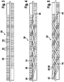
- FIG. 1 shows in a sectional view part of a stator winding 10 for an electric machine, in particular for a generator of a motor vehicle.
- the stator winding 10 is designed as an ordered stator winding 10 and held in a stator core 12 -in sectional view.
- the stator winding 10 has a conductor / wire 14, from each of which an inner winding 16 and an outer winding 18 are formed on two sides of the stator core 12, that is in each case in the winding head 13.
- the outer winding 18 encloses the inner winding 16 in each case.
- the inner winding 16 extends to a first floor 22 and the outer winding 18 to a second floor 24.
- the floors 22, 24 are spaced apart in the axial direction.
- Inner and outer windings 16, 18 are aligned in the same direction here.
- FIG. 2 again shows in simplified form, a part of a stator winding 10 which is held in a stator core 12.
- FIG. 1 FIG. 2 illustrates that even several windings 16, 18, 26 can be wound on each other and / or side by side, in particular axially to each other and / or radially adjacent. It would also be possible, but not shown here, to surround the windings 18, 26 with additional windings.
- FIGS. 3, 4 and 5 will now be shown how the proposed stator winding can be produced, for example.
- a winding bar 28 with a central web 30, a large plurality of rungs 32 and the grooves 33 located therebetween.
- FIGS. 4 and 5 It will now be shown how the inner winding 16 (FIG. FIG. 4 ) and the outer winding 18 (FIG. FIG. 5 ) are applied to the winding bar 28.
- the front side of the winding bar 28 (here, the visible side) shows the terminal side (B side) with the lead wires, while the rear side shows the driving side (A side).
- the conductor 14 is shown in two different variants: If the conductor 14 in the diagram covers the central web 30 and / or the rungs 32, this means that the conductor 14 on the B Page runs.
- the conductor 14 is shown with only two lines, so that the central web 30 and the rungs 32 can still be seen, then this is to show the course of the conductor 14 on the A side.
- the conductor 14 is wavy starting from an inner winding start point 34 alternately on the A side and the B side to an inner reversal point 36.
- the conductor 14 changes from the B side to the A side, and then again waved alternately via the A side and the B side to an inner winding end point 38 of the inner winding 16.
- the Ladder 14 here advantageously designed in one piece, so that the inner winding end point 38 coincides with the outer winding start point 40.
- the conductor 14 is led from there to a turning point 42. From here, the conductor 14 is waved alternately on the A-side and the B-side to an outer reversal point 44. Here, the conductor 14 changes from the B-side to the A-side and is in turn waved alternately on the A-side and the B-side to the outer winding end point 46.
- the principle of manufacturing a multi-layer stator winding 10 is explained.
- the production of the second half of the inner winding is analogous to the production of the first half, but now working towards the other end of the winding beam.
- the outer winding is created according to the same principle.
- the winding is taken from the winding bar and embossed so that it does not apply in the later installed state in the axial and / or radial direction.
Landscapes
- Engineering & Computer Science (AREA)
- Power Engineering (AREA)
- Manufacturing & Machinery (AREA)
- Manufacture Of Motors, Generators (AREA)
- Windings For Motors And Generators (AREA)
Applications Claiming Priority (2)
| Application Number | Priority Date | Filing Date | Title |
|---|---|---|---|
| DE102005037463A DE102005037463A1 (de) | 2005-08-09 | 2005-08-09 | Elektrische Maschine mit mehretagiger Wicklung |
| PCT/EP2006/063928 WO2007017322A1 (de) | 2005-08-09 | 2006-07-06 | Elektrische maschine mit mehretagiger wicklung |
Publications (2)
| Publication Number | Publication Date |
|---|---|
| EP1915812A1 EP1915812A1 (de) | 2008-04-30 |
| EP1915812B1 true EP1915812B1 (de) | 2017-05-31 |
Family
ID=36940016
Family Applications (1)
| Application Number | Title | Priority Date | Filing Date |
|---|---|---|---|
| EP06764081.3A Ceased EP1915812B1 (de) | 2005-08-09 | 2006-07-06 | Elektrische maschine mit mehretagiger wicklung |
Country Status (6)
| Country | Link |
|---|---|
| US (1) | US8456052B2 (ko) |
| EP (1) | EP1915812B1 (ko) |
| KR (1) | KR101025150B1 (ko) |
| CN (1) | CN101283498B (ko) |
| DE (1) | DE102005037463A1 (ko) |
| WO (1) | WO2007017322A1 (ko) |
Families Citing this family (4)
| Publication number | Priority date | Publication date | Assignee | Title |
|---|---|---|---|---|
| DK2629401T3 (en) * | 2012-02-20 | 2015-03-02 | Alstom Renewable Technologies | Generator |
| FR3020205B1 (fr) | 2014-04-17 | 2017-11-03 | Valeo Equip Electr Moteur | Procede de realisation d'un bobinage de stator de machine electrique comportant une etape de pre-formation et stator bobine correspondant |
| FR3020207B1 (fr) * | 2014-04-17 | 2018-03-02 | Valeo Equipements Electriques Moteur | Procede de realisation d'un bobinage d'un stator de machine electrique et stator correspondant |
| DE102019208227A1 (de) * | 2019-06-05 | 2020-12-10 | Volkswagen Aktiengesellschaft | Verfahren zur Herstellung einer Statorwicklung und Elektromaschine |
Family Cites Families (13)
| Publication number | Priority date | Publication date | Assignee | Title |
|---|---|---|---|---|
| JPH0732551B2 (ja) * | 1985-04-15 | 1995-04-10 | 株式会社日立製作所 | 回転電機子コイルの成形方法 |
| US5299749A (en) * | 1992-03-24 | 1994-04-05 | Air Products And Chemicals, Inc. | Method of winding hollow fiber membranes |
| JP3078288B1 (ja) * | 2000-01-25 | 2000-08-21 | 三菱電機株式会社 | 車両用交流発電機 |
| JP3707606B2 (ja) * | 2000-02-07 | 2005-10-19 | 三菱電機株式会社 | 回転電機の巻線組立およびその製造方法ならびにその巻線組立を用いた回転電機の固定子 |
| JP3621635B2 (ja) * | 2000-08-10 | 2005-02-16 | 三菱電機株式会社 | 回転電機 |
| DE10146922A1 (de) * | 2000-09-25 | 2002-04-18 | Denso Corp | Drehfeldmaschine und Verfahren zur Herstellung derselben |
| JP3621636B2 (ja) | 2000-10-16 | 2005-02-16 | 三菱電機株式会社 | 交流発電機の固定子及びその製造方法 |
| JP3676707B2 (ja) * | 2001-07-18 | 2005-07-27 | 三菱電機株式会社 | 車両用交流発電機の固定子およびその製造方法 |
| DE10208566A1 (de) * | 2002-02-27 | 2003-09-11 | Joerg Bobzin | Elektrische Spule und/oder Wicklung mit einseitig zum Spulenbündel liegendem Stromeingang und Stromausgang und deren Herstellungsverfahren |
| JP3736754B2 (ja) * | 2002-03-01 | 2006-01-18 | 株式会社デンソー | 車両用交流発電機の固定子 |
| US6979926B2 (en) * | 2002-06-12 | 2005-12-27 | Denso Corporation | Sequentially joined-segment coil for rotary electrical machine |
| EP1416610B1 (en) | 2002-10-08 | 2005-12-28 | Mitsubishi Denki Kabushiki Kaisha | Stator for an automotive alternator |
| FR2888059B1 (fr) | 2005-06-30 | 2007-09-07 | Valeo Equip Electr Moteur | Enroulement de phase pour un stator de machine electrique tournante et stator equipe d'un tel enroulement de phase |
-
2005
- 2005-08-09 DE DE102005037463A patent/DE102005037463A1/de not_active Withdrawn
-
2006
- 2006-07-06 KR KR1020087003205A patent/KR101025150B1/ko active IP Right Grant
- 2006-07-06 US US12/063,260 patent/US8456052B2/en active Active
- 2006-07-06 EP EP06764081.3A patent/EP1915812B1/de not_active Ceased
- 2006-07-06 WO PCT/EP2006/063928 patent/WO2007017322A1/de active Application Filing
- 2006-07-06 CN CN2006800375203A patent/CN101283498B/zh not_active Expired - Fee Related
Non-Patent Citations (1)
| Title |
|---|
| None * |
Also Published As
| Publication number | Publication date |
|---|---|
| KR101025150B1 (ko) | 2011-03-31 |
| CN101283498A (zh) | 2008-10-08 |
| US8456052B2 (en) | 2013-06-04 |
| EP1915812A1 (de) | 2008-04-30 |
| US20100033052A1 (en) | 2010-02-11 |
| CN101283498B (zh) | 2013-02-13 |
| DE102005037463A1 (de) | 2007-03-01 |
| KR20080035613A (ko) | 2008-04-23 |
| WO2007017322A1 (de) | 2007-02-15 |
Similar Documents
| Publication | Publication Date | Title |
|---|---|---|
| EP3542446B1 (de) | Wellenwicklungsspule für ein statorblechpaket einer elektrischen maschine | |
| EP1171945B1 (de) | Verfahren zur herstellung eines magnetisch erregbaren kerns mit kernwicklung für eine elektrische maschine | |
| EP3695489B1 (de) | Stator für eine elektrische maschine | |
| DE60309539T2 (de) | Mehrzahl von Leiterabschnitten Statorwicklungen für elektrische Drehmaschinen, und Verfahren zu seiner Herstellung | |
| EP1494338B1 (de) | Herstellungsverfahren eines Kerns einer elektrischen Maschine | |
| EP3357141B1 (de) | Im stecktechnikverfahren hergestellter stator oder rotor einer elektrischen maschine mit verkürzter blechlänge | |
| EP1915812B1 (de) | Elektrische maschine mit mehretagiger wicklung | |
| EP1494337A2 (de) | Verfahren zum Herstellen einer zweischichtigen Schleifenwicklung | |
| EP4173119B1 (de) | Stator für eine elektrische maschine und verfahren zum aufbringen einer hairpin-wicklung auf einen statorkörper | |
| WO2015000639A2 (de) | Maschinenkomponente für eine elektrische maschine mit mehreren wicklungen | |
| EP3167540B1 (de) | Verfahren zum herstellen einer elektrischen maschine mit formspulen sowie elektrische maschine und herstellungswerkzeug | |
| EP2680414B1 (de) | Verfahren zur Herstellung einer Spule für einen Generator einer Windkraftanlage | |
| AT522206B1 (de) | Verfahren zum Bereitstellen von Formstäben aus einem elektrischen Leiterdraht sowie entsprechende Formstäbe | |
| EP4165754A1 (de) | Stator für eine elektrische maschine, sowie elektrische maschine | |
| DE102020207906A1 (de) | Verteilte Wicklung | |
| WO2016096246A1 (de) | Wicklungsanordnung und elektrische maschine mit einer derartigen wicklungsanordnung | |
| DE102020212358A1 (de) | Verfahren zur Herstellung eines geschrägten Stators | |
| DE10260311A1 (de) | Mehrfachspulen und Träufelwicklungen aus Litze sowie entsprechendes Herstellungsverfahren | |
| WO2022218885A1 (de) | Stator für eine elektrische maschine, verfahren zur herstellung eines stators für eine elektrische maschine, elektrische maschine und fahrzeug | |
| DE102021124996A1 (de) | Verfahren zur Herstellung einer Wicklung für einen Stator einer elektrischen Rotationsmaschine, Stator, Verfahren zur Herstellung des Stators und elektrische Rotationsmaschine | |
| WO2021047727A1 (de) | Bandförmige wicklungseinheit für eine statorwicklung und verfahren zur herstellung einer bandförmigen wicklungseinheit | |
| DE102020116383A1 (de) | Verfahren zur Herstellung eines geschrägten Stators | |
| DE102020207499A1 (de) | Stator für einen Elektromotor | |
| DE102021125488A1 (de) | Stator einer elektrischen Rotationsmaschine sowie elektrische Rotationsmaschine | |
| DE10138523A1 (de) | Wicklung für eine elektrische Maschine, sowie Verfahren zur Herstellung einer Wicklung für eine elektrische Maschine |
Legal Events
| Date | Code | Title | Description |
|---|---|---|---|
| PUAI | Public reference made under article 153(3) epc to a published international application that has entered the european phase |
Free format text: ORIGINAL CODE: 0009012 |
|
| 17P | Request for examination filed |
Effective date: 20080310 |
|
| AK | Designated contracting states |
Kind code of ref document: A1 Designated state(s): DE FR IT |
|
| RBV | Designated contracting states (corrected) |
Designated state(s): DE FR IT |
|
| 17Q | First examination report despatched |
Effective date: 20100602 |
|
| DAX | Request for extension of the european patent (deleted) | ||
| GRAP | Despatch of communication of intention to grant a patent |
Free format text: ORIGINAL CODE: EPIDOSNIGR1 |
|
| INTG | Intention to grant announced |
Effective date: 20170309 |
|
| GRAS | Grant fee paid |
Free format text: ORIGINAL CODE: EPIDOSNIGR3 |
|
| GRAA | (expected) grant |
Free format text: ORIGINAL CODE: 0009210 |
|
| AK | Designated contracting states |
Kind code of ref document: B1 Designated state(s): DE FR IT |
|
| REG | Reference to a national code |
Ref country code: DE Ref legal event code: R096 Ref document number: 502006015524 Country of ref document: DE |
|
| REG | Reference to a national code |
Ref country code: FR Ref legal event code: PLFP Year of fee payment: 12 |
|
| REG | Reference to a national code |
Ref country code: DE Ref legal event code: R081 Ref document number: 502006015524 Country of ref document: DE Owner name: SEG AUTOMOTIVE GERMANY GMBH, DE Free format text: FORMER OWNER: ROBERT BOSCH GMBH, 70469 STUTTGART, DE |
|
| REG | Reference to a national code |
Ref country code: DE Ref legal event code: R097 Ref document number: 502006015524 Country of ref document: DE |
|
| PLBE | No opposition filed within time limit |
Free format text: ORIGINAL CODE: 0009261 |
|
| STAA | Information on the status of an ep patent application or granted ep patent |
Free format text: STATUS: NO OPPOSITION FILED WITHIN TIME LIMIT |
|
| REG | Reference to a national code |
Ref country code: FR Ref legal event code: TP Owner name: SEG AUTOMOTIVE GERMANY GMBH, DE Effective date: 20180315 |
|
| 26N | No opposition filed |
Effective date: 20180301 |
|
| REG | Reference to a national code |
Ref country code: FR Ref legal event code: PLFP Year of fee payment: 13 |
|
| PGFP | Annual fee paid to national office [announced via postgrant information from national office to epo] |
Ref country code: FR Payment date: 20210722 Year of fee payment: 16 Ref country code: IT Payment date: 20210726 Year of fee payment: 16 |
|
| PGFP | Annual fee paid to national office [announced via postgrant information from national office to epo] |
Ref country code: DE Payment date: 20210723 Year of fee payment: 16 |
|
| REG | Reference to a national code |
Ref country code: DE Ref legal event code: R082 Ref document number: 502006015524 Country of ref document: DE Representative=s name: DEHNSGERMANY PARTNERSCHAFT VON PATENTANWAELTEN, DE |
|
| REG | Reference to a national code |
Ref country code: DE Ref legal event code: R119 Ref document number: 502006015524 Country of ref document: DE |
|
| PG25 | Lapsed in a contracting state [announced via postgrant information from national office to epo] |
Ref country code: FR Free format text: LAPSE BECAUSE OF NON-PAYMENT OF DUE FEES Effective date: 20220731 |
|
| PG25 | Lapsed in a contracting state [announced via postgrant information from national office to epo] |
Ref country code: DE Free format text: LAPSE BECAUSE OF NON-PAYMENT OF DUE FEES Effective date: 20230201 |
|
| PG25 | Lapsed in a contracting state [announced via postgrant information from national office to epo] |
Ref country code: IT Free format text: LAPSE BECAUSE OF NON-PAYMENT OF DUE FEES Effective date: 20220706 |