EP1915812B1 - Electric machine with a multi-level winding - Google Patents
Electric machine with a multi-level winding Download PDFInfo
- Publication number
- EP1915812B1 EP1915812B1 EP06764081.3A EP06764081A EP1915812B1 EP 1915812 B1 EP1915812 B1 EP 1915812B1 EP 06764081 A EP06764081 A EP 06764081A EP 1915812 B1 EP1915812 B1 EP 1915812B1
- Authority
- EP
- European Patent Office
- Prior art keywords
- winding
- stator
- stator winding
- producing
- wire
- Prior art date
- Legal status (The legal status is an assumption and is not a legal conclusion. Google has not performed a legal analysis and makes no representation as to the accuracy of the status listed.)
- Expired - Fee Related
Links
Images

Classifications
-
- H—ELECTRICITY
- H02—GENERATION; CONVERSION OR DISTRIBUTION OF ELECTRIC POWER
- H02K—DYNAMO-ELECTRIC MACHINES
- H02K3/00—Details of windings
- H02K3/04—Windings characterised by the conductor shape, form or construction, e.g. with bar conductors
- H02K3/12—Windings characterised by the conductor shape, form or construction, e.g. with bar conductors arranged in slots
-
- H—ELECTRICITY
- H02—GENERATION; CONVERSION OR DISTRIBUTION OF ELECTRIC POWER
- H02K—DYNAMO-ELECTRIC MACHINES
- H02K15/00—Methods or apparatus specially adapted for manufacturing, assembling, maintaining or repairing of dynamo-electric machines
- H02K15/04—Methods or apparatus specially adapted for manufacturing, assembling, maintaining or repairing of dynamo-electric machines of windings, prior to mounting into machines
- H02K15/0435—Wound windings
- H02K15/0478—Wave windings, undulated windings
-
- Y—GENERAL TAGGING OF NEW TECHNOLOGICAL DEVELOPMENTS; GENERAL TAGGING OF CROSS-SECTIONAL TECHNOLOGIES SPANNING OVER SEVERAL SECTIONS OF THE IPC; TECHNICAL SUBJECTS COVERED BY FORMER USPC CROSS-REFERENCE ART COLLECTIONS [XRACs] AND DIGESTS
- Y10—TECHNICAL SUBJECTS COVERED BY FORMER USPC
- Y10T—TECHNICAL SUBJECTS COVERED BY FORMER US CLASSIFICATION
- Y10T29/00—Metal working
- Y10T29/49—Method of mechanical manufacture
- Y10T29/49002—Electrical device making
- Y10T29/49009—Dynamoelectric machine
-
- Y—GENERAL TAGGING OF NEW TECHNOLOGICAL DEVELOPMENTS; GENERAL TAGGING OF CROSS-SECTIONAL TECHNOLOGIES SPANNING OVER SEVERAL SECTIONS OF THE IPC; TECHNICAL SUBJECTS COVERED BY FORMER USPC CROSS-REFERENCE ART COLLECTIONS [XRACs] AND DIGESTS
- Y10—TECHNICAL SUBJECTS COVERED BY FORMER USPC
- Y10T—TECHNICAL SUBJECTS COVERED BY FORMER US CLASSIFICATION
- Y10T29/00—Metal working
- Y10T29/49—Method of mechanical manufacture
- Y10T29/49002—Electrical device making
- Y10T29/4902—Electromagnet, transformer or inductor
- Y10T29/49071—Electromagnet, transformer or inductor by winding or coiling
Definitions
- the invention relates to a method for producing a stator winding of an electrical machine.
- Electric machines according to the preamble of claim 1 are known from the prior art. They are operated as electric motors, electric generators or changing operating conditions for a while as an electric motor and for a time as an electric generator. Of particular interest is the use of an electric machine as a generator in a motor vehicle. Due to the increasing performance requirements within a motor vehicle and the limited space available, it is a constant effort to develop electrical machines that are efficient, compact and have a long life expectancy.
- the invention is a method as defined in claim 1.
- Advantageous embodiments of the invention are defined in the dependent claims 2-17.
- stator winding for an electrical machine, in particular for a generator of a motor vehicle
- stator winding is designed as an ordered winding and the stator winding is carried out in a winding head in at least two axially spaced floors.
- axial is to be understood as the reference to the axis of rotation of the electric machine, in which the stator winding is used.
- stator winding designed in this way results in a structured, well-ventilated winding head, which has advantageous mechanical properties and stable electrical properties.
- the winding head with the stator winding can be used both in a round shaped laminated core ("open slot") and in a flat package.
- a flat package is to be understood as meaning that the stator core lies flat when the windings of the stator winding are introduced. It is then bent to a round stator pack, after which usually the joints are welded. Since the stator winding is constructed in an orderly manner, the part held in the winding head can be shaped in a defined manner in each production stage. In addition, it has been shown in experiments that the use of such a stator winding at high speeds causes only a low flow noise. It is expressly pointed out that the stator winding can also be constructed with more than two floors.
- the advantages of such a method are manifested in particular in the fact that a continuous conductor can be used and that during the manufacturing process, it is possible to introduce cranks and / or stampings.
- the stator winding is produced by means of a rotating winding beam. This allows a cheaper production, since no longer a variety of winding devices must be used. It is particularly advantageous if all phases are wound simultaneously, since thus the winding times are shortened.
- the stator winding is made with an inner and an outer winding, the outer winding enclosing the inner winding. This results in a favorable structure, which already enjoys the advantages of the invention. It is not necessary that the outer winding of the inner winding completely encloses.
- the stator winding is designed as a wave winding and has at least one reversal point. Such a winding can be easily manufactured and due to the continuation in the reversal points allows a smaller number of conductors, which still have to be connected in a further step.
- At least one phase of the stator winding is made of a one-piece, continuous conductor. This results in a further simplification of the manufacturing process.
- the inner and outer coils are aligned in the same direction. This means that the leadership of the respective wire goes in the same direction, so to speak, takes place in parallel.
- the stator winding is made of a rectangular wire, wherein the St forglall hormone in particular greater than 55%.
- the stator fill factor is known to be the ratio of the sum of all conductor cross sections without insulation (ie in particular the copper cross sections) in a groove to the total cross-sectional area of the groove.
- the conductor is embossed in the winding head. It is possible to apply embossments and / or cranks of the conductor, in particular a copper wire, since all conductors / wires are accessible during the winding process.
- the stator winding is inserted in a flat package or in a stand with open grooves. Moreover, it is advantageous if the stator winding is carried out with round wire and the wire sections which come to rest within the slots of the stator core are embossed. This can be done in an intermediate step or in a final step. In this way, the wires take on the shape of the groove.
- the width of the wires of the winding corresponds approximately to the groove width. There are no wires side by side, and the risk of wire crossing or slipping of wires is reduced or eliminated.
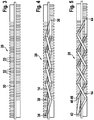
- FIG. 1 shows in a sectional view part of a stator winding 10 for an electric machine, in particular for a generator of a motor vehicle.
- the stator winding 10 is designed as an ordered stator winding 10 and held in a stator core 12 -in sectional view.
- the stator winding 10 has a conductor / wire 14, from each of which an inner winding 16 and an outer winding 18 are formed on two sides of the stator core 12, that is in each case in the winding head 13.
- the outer winding 18 encloses the inner winding 16 in each case.
- the inner winding 16 extends to a first floor 22 and the outer winding 18 to a second floor 24.
- the floors 22, 24 are spaced apart in the axial direction.
- Inner and outer windings 16, 18 are aligned in the same direction here.
- FIG. 2 again shows in simplified form, a part of a stator winding 10 which is held in a stator core 12.
- FIG. 1 FIG. 2 illustrates that even several windings 16, 18, 26 can be wound on each other and / or side by side, in particular axially to each other and / or radially adjacent. It would also be possible, but not shown here, to surround the windings 18, 26 with additional windings.
- FIGS. 3, 4 and 5 will now be shown how the proposed stator winding can be produced, for example.
- a winding bar 28 with a central web 30, a large plurality of rungs 32 and the grooves 33 located therebetween.
- FIGS. 4 and 5 It will now be shown how the inner winding 16 (FIG. FIG. 4 ) and the outer winding 18 (FIG. FIG. 5 ) are applied to the winding bar 28.
- the front side of the winding bar 28 (here, the visible side) shows the terminal side (B side) with the lead wires, while the rear side shows the driving side (A side).
- the conductor 14 is shown in two different variants: If the conductor 14 in the diagram covers the central web 30 and / or the rungs 32, this means that the conductor 14 on the B Page runs.
- the conductor 14 is shown with only two lines, so that the central web 30 and the rungs 32 can still be seen, then this is to show the course of the conductor 14 on the A side.
- the conductor 14 is wavy starting from an inner winding start point 34 alternately on the A side and the B side to an inner reversal point 36.
- the conductor 14 changes from the B side to the A side, and then again waved alternately via the A side and the B side to an inner winding end point 38 of the inner winding 16.
- the Ladder 14 here advantageously designed in one piece, so that the inner winding end point 38 coincides with the outer winding start point 40.
- the conductor 14 is led from there to a turning point 42. From here, the conductor 14 is waved alternately on the A-side and the B-side to an outer reversal point 44. Here, the conductor 14 changes from the B-side to the A-side and is in turn waved alternately on the A-side and the B-side to the outer winding end point 46.
- the principle of manufacturing a multi-layer stator winding 10 is explained.
- the production of the second half of the inner winding is analogous to the production of the first half, but now working towards the other end of the winding beam.
- the outer winding is created according to the same principle.
- the winding is taken from the winding bar and embossed so that it does not apply in the later installed state in the axial and / or radial direction.
Description
Die Erfindung betrifft ein Verfahren zur Herstellung einer Ständerwicklung einer elektrischen Maschine.The invention relates to a method for producing a stator winding of an electrical machine.
Elektrische Maschinen gemäß dem Oberbegriff des Anspruchs 1 sind aus dem Stand der Technik bekannt. Sie werden dabei als elektrische Motoren, elektrische Generatoren oder bei wechselnden Betriebszuständen eine Zeit lang als elektrischer Motor und eine Zeit lang als elektrischer Generator betrieben. Von großem Interesse ist dabei insbesondere der Einsatz einer elektrischen Maschine als Generator in einem Kraftfahrzeug. Aufgrund der steigenden Leistungsanforderungen innerhalb eines Kraftfahrzeugs sowie dem geringen Bauraum, der zur Verfügung steht, ist es ein stetes Bestreben elektrische Maschinen zu entwickeln, die effizient arbeiten, kompakt gebaut sind und eine hohe Lebenserwartung aufweisen.Electric machines according to the preamble of claim 1 are known from the prior art. They are operated as electric motors, electric generators or changing operating conditions for a while as an electric motor and for a time as an electric generator. Of particular interest is the use of an electric machine as a generator in a motor vehicle. Due to the increasing performance requirements within a motor vehicle and the limited space available, it is a constant effort to develop electrical machines that are efficient, compact and have a long life expectancy.
Aus der Offenlegungsschrift
Die Erfindung ist ein Verfahren wie in Anspruch 1 definiert. Vorteilhafte Ausgestaltungsformen der Erfindung sind in den abhängigen Ansprüchen 2 - 17 definiert.The invention is a method as defined in claim 1. Advantageous embodiments of the invention are defined in the dependent claims 2-17.
Bei dem Verfahren zur Herstellung einer Ständerwicklung für eine elektrische Maschine, insbesondere für einen Generator eines Kraftfahrzeugs, ist es erfindungsgemäß vorgesehen, dass die Ständerwicklung als geordnete Wicklung ausgeführt wird und die Ständerwicklung in einem Wickelkopf in mindestens zwei axial beabstandeten Etagen ausgeführt wird. Unter dem Begriff "axial" ist dabei der Bezug auf die Drehachse der elektrischen Maschine zu verstehen, in die die Ständerwicklung eingesetzt wird. Bei einer derartig ausgeführten Ständerwicklung ergibt sich ein strukturierter, gut durchlüfteter Wickelkopf, der vorteilhafte mechanische Eigenschaften und stabile elektrische Eigenschaften aufweist. Der Wickelkopf mit der Ständerwicklung kann dabei sowohl in einem rund geformten Blechpaket ("open slot") als auch in einem Flachpaket verwendet werden. Unter einem Flachpaket soll verstanden werden, dass das Ständerpaket flach ausliegt, wenn die Wicklungen der Ständerwicklung eingebracht werden. Es wird danach zu einem runden Ständerpaket gebogen, wonach üblicherweise die Stoßstellen verschweißt werden. Da die Ständerwicklung geordnet aufgebaut wird, kann der im Wickelkopf gehaltene Teil in jeder Fertigungsstufe definiert in Form gebracht werden. Zudem hat sich in Versuchen gezeigt, dass der Einsatz einer derartigen Ständerwicklung bei hohen Drehzahlen lediglich ein geringes Strömungsgeräusch hervorruft. Es sei ausdrücklich darauf hingewiesen, dass die Ständerwicklung auch mit mehr als zwei Etagen aufgebaut werden kann. Handelt es sich um einen Wickelkopf mit einem im Wesentlichen symmetrischen Aufbau auf zwei Seiten, so ist zu beachten, dass im Sinne der Erfindung, die Etagen auf beiden Seiten nicht zusammengezählt werden, sondern auf mindestens einer der beiden Seiten, insbesondere auf beiden Seiten, aufzufinden sind. Erfindungsgemäß wird zunächst eine innere Wicklung und dann eine axial zur inneren Wicklung beabstandete äußere Wicklung um die innere Wicklung hergestellt. Es ergibt sich also eine Wicklung, die in axialer Richtung aufträgt. Sollte es erforderlich sein, kann der axiale Auftrag durch eine entsprechende Verkürzung der inneren Wickelköpfe ausgeglichen werden. Es ergibt sich bei diesem Vorgehen der Vorteil, dass die Wicklung kontinuierlich mit allen Phasen gleichzeitig gewickelt werden kann. Die Vorteile eines solchen Verfahrens manifestieren sich insbesondere darin, dass ein durchgehender Leiter verwendet werden kann und dass während des Herstellungsprozesses Kröpfungen und/oder Verprägungen eingebracht werden können. Die Ständerwicklung wird mittels eines rotierenden Wickelbalkens hergestellt. Dies erlaubt eine preiswertere Fertigung, da nicht mehr eine Vielzahl an Wickeleinrichtungen verwendet werden muss. Dabei ist es besonders vorteilhaft, wenn alle Phasen gleichzeitig gewickelt werden, da damit die Wickelzeiten verkürzt werden. Die Ständerwicklung wird mit einer inneren und einer äußeren Wicklung hergestellt, wobei die äußere Wicklung die innere Wicklung umschließt. Dadurch ergibt sich ein günstiger Aufbau, der bereits die Vorteile der Erfindung genießt. Dabei ist es nicht erforderlich, dass die äußere Wicklung die innere Wicklung vollständig umschließt. Vielmehr ist es ausreichend, wenn die äußere Wicklung die innere Wicklung teilweise umgibt. Die Ständerwicklung wird als Wellenwicklung ausgeführt und weist dabei mindestens einen Umkehrpunkt auf. Eine derartige Wicklung kann einfach hergestellt werden und erlaubt aufgrund der Weiterführung in den Umkehrpunkten eine geringere Anzahl an Leitern, die in einem weiteren Schritt noch verbunden werden müssen.In the method for producing a stator winding for an electrical machine, in particular for a generator of a motor vehicle, it is provided according to the invention that the stator winding is designed as an ordered winding and the stator winding is carried out in a winding head in at least two axially spaced floors. The term "axial" is to be understood as the reference to the axis of rotation of the electric machine, in which the stator winding is used. In a stator winding designed in this way results in a structured, well-ventilated winding head, which has advantageous mechanical properties and stable electrical properties. The winding head with the stator winding can be used both in a round shaped laminated core ("open slot") and in a flat package. A flat package is to be understood as meaning that the stator core lies flat when the windings of the stator winding are introduced. It is then bent to a round stator pack, after which usually the joints are welded. Since the stator winding is constructed in an orderly manner, the part held in the winding head can be shaped in a defined manner in each production stage. In addition, it has been shown in experiments that the use of such a stator winding at high speeds causes only a low flow noise. It is expressly pointed out that the stator winding can also be constructed with more than two floors. Is it a winding head with a substantially symmetrical structure on two Pages, it should be noted that in the context of the invention, the floors are not added together on both sides, but on at least one of the two sides, in particular on both sides, are found. According to the invention, an inner winding and then an outer winding spaced axially from the inner winding are first produced around the inner winding. This results in a winding that applies in the axial direction. Should it be necessary, the axial order can be compensated by a corresponding shortening of the inner winding heads. This results in the advantage that the winding can be wound continuously with all phases simultaneously. The advantages of such a method are manifested in particular in the fact that a continuous conductor can be used and that during the manufacturing process, it is possible to introduce cranks and / or stampings. The stator winding is produced by means of a rotating winding beam. This allows a cheaper production, since no longer a variety of winding devices must be used. It is particularly advantageous if all phases are wound simultaneously, since thus the winding times are shortened. The stator winding is made with an inner and an outer winding, the outer winding enclosing the inner winding. This results in a favorable structure, which already enjoys the advantages of the invention. It is not necessary that the outer winding of the inner winding completely encloses. Rather, it is sufficient if the outer winding partially surrounds the inner winding. The stator winding is designed as a wave winding and has at least one reversal point. Such a winding can be easily manufactured and due to the continuation in the reversal points allows a smaller number of conductors, which still have to be connected in a further step.
Bevorzugt wird mindestens eine Phase der Ständerwicklung aus einem einstückigen, durchgehenden Leiter gefertigt. Somit ergibt sich eine weitere Vereinfachung des Herstellungsverfahrens.Preferably, at least one phase of the stator winding is made of a one-piece, continuous conductor. This results in a further simplification of the manufacturing process.
Ferner ist es bevorzugt, dass die innere und die äußere Wicklung in die gleiche Richtung ausgerichtet wird. Dies bedeutet, dass die Führung des jeweiligen Drahts in die gleiche Richtung geht, also gewissermaßen parallel erfolgt.Further, it is preferable that the inner and outer coils are aligned in the same direction. This means that the leadership of the respective wire goes in the same direction, so to speak, takes place in parallel.
Mit Vorteil ist die Ständerwicklung aus einem Rechteckdraht ausgeführt, wobei der Ständerfüllfaktor insbesondere größer als 55 % ist. Der Ständerfüllfaktor ist bekanntermaßen das Verhältnis der Summe aller Leiterquerschnitte ohne Isolation (also insbesondere der Kupferquerschnitte) in einer Nut zur Gesamt-Querschnittsfläche der Nut. Mittels eines Rechteckdrahts kann ein besonders hoher Ständerfüllfaktor erreicht werden, wobei ein hoher Ständerfüllfaktor wiederum eine besonders gute Effizienz der Maschine ergibt. Zudem ergibt sich durch die Zähne des Ständers in Verbindung mit dem Draht/Leiter eine Klammerfunktion, sodass während des Einbringens der Drähte und während des späteren Betriebs ein Verrutschen ausgeschlossen ist.Advantageously, the stator winding is made of a rectangular wire, wherein the Ständerfüllfaktor in particular greater than 55%. The stator fill factor is known to be the ratio of the sum of all conductor cross sections without insulation (ie in particular the copper cross sections) in a groove to the total cross-sectional area of the groove. By means of a rectangular wire, a particularly high Ständerfüllfaktor can be achieved, with a high Ständerfüllfaktor in turn results in a particularly good efficiency of the machine. In addition, resulting from the teeth of the stand in conjunction with the wire / conductor a staple function, so during insertion the wires and during later operation slipping is excluded.
Gemäß einer Weiterbildung der Erfindung wird der Leiter im Wickelkopf verprägt. Es ist möglich Verprägungen und/oder Kröpfungen des Leiters, insbesondere eines Kupferdrahts, anzubringen, da alle Leiter/Drähte während des Wickelvorgangs zugänglich sind.According to one embodiment of the invention, the conductor is embossed in the winding head. It is possible to apply embossments and / or cranks of the conductor, in particular a copper wire, since all conductors / wires are accessible during the winding process.
Vorteilhafterweise wird die Ständerwicklung in ein Flachpaket oder in einen Ständer mit offenen Nuten eingelegt. Außerdem ist es vorteilhaft, wenn die Ständerwicklung mit Runddraht ausgeführt wird und die Drahtabschnitte, die innerhalb der Nuten des Ständerpakets zu liegen kommen, verprägt werden. Dies kann in einem Zwischenschritt oder in einem Abschlussschritt erfolgen. Auf diese Weise nehmen die Drähte die Form der Nut an.Advantageously, the stator winding is inserted in a flat package or in a stand with open grooves. Moreover, it is advantageous if the stator winding is carried out with round wire and the wire sections which come to rest within the slots of the stator core are embossed. This can be done in an intermediate step or in a final step. In this way, the wires take on the shape of the groove.
Ferner ist es bevorzugt, dass die Breite der Drähte der Wicklung in etwa der Nutbreite entspricht. Damit liegen keine Drähte nebeneinander, und die Gefahr von Drahtkreuzungen oder eines Verrutschen von Drähten wird verringert oder eliminiert.Furthermore, it is preferred that the width of the wires of the winding corresponds approximately to the groove width. There are no wires side by side, and the risk of wire crossing or slipping of wires is reduced or eliminated.
Dabei ist es vorteilhaft, wenn die Maschine mehr als drei Phasen aufweist. Es gilt ungefähr, dass das Verhältnis der Drahtbreite b zur Anzahl s der Phasen ![]()
![]()
Schließlich ist es bevorzugt, wenn mindestens einmal auf der gleichen Seite des Wickelbalkens weitergewickelt wird und/oder mindestens einmal ein Kröpfen oder Verprägen der Drähte auf dem Wickelbalken erfolgt.Finally, it is preferred if at least once further wound on the same side of the winding beam and / or at least once done crimping or embossing of the wires on the winding bar.
Andere vorteilhafte Ausgestaltungen des Verfahrens sind in weiteren Unteransprüchen enthalten.Other advantageous embodiments of the method are contained in further subclaims.
Die Erfindung wird nun anhand von Ausführungsbeispielen näher erläutert. Es zeigen:
- Figur 1
- ein erstes Ausführungsbeispiel einer zweietagigen Ständerwicklung in einem Wickelkopf,
- Figur 2
- ein zweites Ausführungsbeispiel einer zweietagigen Ständerwicklung in einem Wickelkopf,
- Figur 3
- eine vereinfachte, systematische Darstellung eines Wickelbalkens,
- Figur 4
- das Aufbringen einer inneren Wicklung auf den Wickelbalken und
- Figur 5
- das Aufbringen einer äußeren Wicklung auf den Wickelbalken.
- FIG. 1
- A first embodiment of a two-stage stator winding in a winding head,
- FIG. 2
- A second embodiment of a two-stage stator winding in a winding head,
- FIG. 3
- a simplified, systematic representation of a winding beam,
- FIG. 4
- the application of an inner winding on the winding bar and
- FIG. 5
- the application of an outer winding on the winding bar.
Anhand der
In den
In der
Nachfolgend wird der Herstellungsprozess für eine Ständerwicklung 10 mit allgemein s Phasen detaillierter beschrieben. Es wird dabei vorausgesetzt, dass zu Beginn s Wicklungsanfänge in die ersten s Nuten eingelegt werden. Die Herstellung der ersten Hälfte der inneren Wicklung gestaltet sich dann wie folgt:
- 1. Drehen des Wickelbalkens um 180° und gleichzeitiges Verschieben der Drahtzuführung um s Nuten nach rechts.
- 2. Einlegen der Drähte in die Nuten s+1 bis 2s.
- 3. Drehen des Wickelbalkens um 180° und gleichzeitiges Verschieben der Drahtzuführung um s Nuten nach rechts.
- 4. Einlegen der Drähte in die Nuten s+1 bis 2s.
- 5. Wiederholung dieser Schritte, bis das Ende des Wickelbalkens erreicht ist.
- 6. Am Ende des Wickelbalkens angelangt, entfällt die Drehung des Wickelbalkens. Dann Vorschub um s Nuten und Einlegen der letzten s Drähte erneut auf der gleichen Seite des Wickelbalkens.
- 7. Falls nötig, kann nun die Formung des Wickelkopfes mittels Werkzeugen erfolgen.
- 1. Turn the wrap bar by 180 ° and simultaneously move the wire feed by s slots to the right.
- 2. Insert the wires into the slots s + 1 to 2s.
- 3. Turn the wrap bar by 180 ° and simultaneously move the wire feed by s slots to the right.
- 4. Insert the wires into the slots s + 1 to 2s.
- 5. Repeat these steps until the end of the wrap bar is reached.
- 6. At the end of the wrap bar, the rotation of the wrap bar is eliminated. Then feed by s grooves and insert the last s wires again on the same side of the winding beam.
- 7. If necessary, the forming of the winding head can now be done by means of tools.
Die Herstellung der zweiten Hälfte der inneren Wicklung geschieht analog zur Herstellung der ersten Hälfte, wobei jetzt aber auf das andere Ende des Wickelbalkens hingearbeitet wird. Nachdem die innere Wicklung fertig gestellt ist, wird die äußere Wicklung nach dem gleichen Prinzip erstellt. Wenn die Wicklung insgesamt fertig gestellt ist, wird die Wicklung vom Wickelbalken genommen und verprägt, damit sie im späteren Einbauzustand in axialer und/oder radialer Richtung nicht aufträgt.The production of the second half of the inner winding is analogous to the production of the first half, but now working towards the other end of the winding beam. After the inner winding is completed, the outer winding is created according to the same principle. When the winding is completed as a whole, the winding is taken from the winding bar and embossed so that it does not apply in the later installed state in the axial and / or radial direction.
Claims (17)
- Method for producing a stator winding (10) of an electrical machine for a motor vehicle, which stator winding is embodied as an ordered stator winding (10) with s phases and is embodied in an end winding (13) in at least two axially spaced-apart levels (22, 24), wherein initially an inner winding (16) and then an outer winding (18), which is axially spaced apart from the inner winding (16), around the inner winding (16) are produced, and wherein the stator winding (10) is produced as a wave winding by means of a rotating winding bar (28),
wherein halves of the inner and outer winding are respectively produced one after the other using the following method steps:a) rotating the winding bar through 180° and at the same time shifting the wire feed by s slots to the right;b) inserting the wires into the slots;c) rotating the winding bar through 180° and at the same time shifting the wire feed by s slots to the right;d) then inserting the wires into the slots;e) repeating these steps until the end of the winding bar is reached;f) rotation of the winding bar is stopped when the end of the winding bar is reached;g) then advancing by s slots and inserting the last s wires once again on the same side of the winding bar (28) ;h) repeatedly executing method steps a) to f) for the next half of the inner and outer winding in each case, wherein the other end of the winding bar (28) is worked towards. - Method for producing a stator winding (10) according to Claim 1, characterized in that the stator winding (10) is wound with an inner and an outer winding (16, 18), wherein the outer winding (18) surrounds the inner winding (16).
- Method for producing a stator winding (10) according to either of the preceding claims, characterized in that the stator winding (10) is embodied as a wave winding with at least one reversal point (36, 42, 44).
- Method for producing a stator winding (10) according to one of the preceding claims, characterized in that at least one phase of the stator winding (10) is manufactured from a one-piece, continuous conductor (14).
- Method for producing a stator winding (10) according to one of the preceding claims, characterized in that the inner and the outer winding (16, 18) are oriented in the same direction.
- Method for producing a stator winding (10) according to one of the preceding claims, characterized in that a distance between the levels (22, 24) is approximately between 1 mm and 5 mm.
- Method for producing a stator winding (10) according to one of the preceding claims, characterized in that the stator winding (10) is embodied from a rectangular wire, wherein a stator filling factor is, in particular, greater than 55%.
- Method for producing a stator winding (10) according to one of the preceding claims, characterized in that an even number of the conductors (14), in particular four or a multiple of four, is arranged in a slot.
- Method for producing a stator winding (10) according to one of the preceding claims, characterized in that the conductor (14) is stamped in the end winding (13).
- Method for producing a stator winding (10) according to one of the preceding claims, characterized in that the stator winding (10) is inserted into a flat core and/or into a stator with open slots.
- Method for producing a stator winding (10) according to one of the preceding claims, characterized in that the stator winding (10) is embodied with a round wire and the wire sections which come to rest within the slots of the stator core (12) are stamped.
- Method for producing a stator winding (10) according to one of the preceding claims, characterized in that the width of the wires of the winding corresponds approximately to the slot width.
- Method according to one of the preceding claims, characterized in that further winding is performed at least once on the same side of the winding bar (28) and/or the wires are bent or stamped at least once on the winding bar (28).
- Method according to one of the preceding claims, characterized in that a continuous wire is used.
- Method according to one of the preceding claims, characterized in that all of the wire sections of a slot, in particular embodied as a round wire, are stamped at the same time.
- Method according to one of the preceding claims, characterized in that a cross-sectional shape of the wire is initially substantially round and is changed in a following step.
- Method according to Claim 16, characterized in that the change in the cross-sectional shape in the slot region takes place in order to match the wire shape to the slot shape and to achieve a high stator filling factor.
Applications Claiming Priority (2)
| Application Number | Priority Date | Filing Date | Title |
|---|---|---|---|
| DE102005037463A DE102005037463A1 (en) | 2005-08-09 | 2005-08-09 | Electric machine with multi-layer winding |
| PCT/EP2006/063928 WO2007017322A1 (en) | 2005-08-09 | 2006-07-06 | Electric machine with a multi-level winding |
Publications (2)
| Publication Number | Publication Date |
|---|---|
| EP1915812A1 EP1915812A1 (en) | 2008-04-30 |
| EP1915812B1 true EP1915812B1 (en) | 2017-05-31 |
Family
ID=36940016
Family Applications (1)
| Application Number | Title | Priority Date | Filing Date |
|---|---|---|---|
| EP06764081.3A Expired - Fee Related EP1915812B1 (en) | 2005-08-09 | 2006-07-06 | Electric machine with a multi-level winding |
Country Status (6)
| Country | Link |
|---|---|
| US (1) | US8456052B2 (en) |
| EP (1) | EP1915812B1 (en) |
| KR (1) | KR101025150B1 (en) |
| CN (1) | CN101283498B (en) |
| DE (1) | DE102005037463A1 (en) |
| WO (1) | WO2007017322A1 (en) |
Families Citing this family (3)
| Publication number | Priority date | Publication date | Assignee | Title |
|---|---|---|---|---|
| ES2532176T3 (en) * | 2012-02-20 | 2015-03-24 | Alstom Renewable Technologies | Generator |
| FR3020207B1 (en) * | 2014-04-17 | 2018-03-02 | Valeo Equipements Electriques Moteur | METHOD FOR MAKING A WINDING OF AN ELECTRIC MACHINE STATOR AND CORRESPONDING STATOR |
| FR3020205B1 (en) * | 2014-04-17 | 2017-11-03 | Valeo Equip Electr Moteur | METHOD FOR MAKING AN ELECTRIC MACHINE STATOR COIL COMPRISING A PREFORMING STEP AND CORRESPONDING COIL STATOR |
Family Cites Families (13)
| Publication number | Priority date | Publication date | Assignee | Title |
|---|---|---|---|---|
| JPH0732551B2 (en) | 1985-04-15 | 1995-04-10 | 株式会社日立製作所 | Method of forming rotating armature coil |
| US5299749A (en) * | 1992-03-24 | 1994-04-05 | Air Products And Chemicals, Inc. | Method of winding hollow fiber membranes |
| JP3078288B1 (en) * | 2000-01-25 | 2000-08-21 | 三菱電機株式会社 | AC generator for vehicles |
| JP3707606B2 (en) * | 2000-02-07 | 2005-10-19 | 三菱電機株式会社 | Winding assembly of rotating electrical machine, manufacturing method thereof, and stator of rotating electrical machine using the winding assembly |
| JP3621635B2 (en) * | 2000-08-10 | 2005-02-16 | 三菱電機株式会社 | Rotating electric machine |
| US6727625B2 (en) * | 2000-09-25 | 2004-04-27 | Denso Corporation | Rotary electric machine and method for manufacturing the same |
| JP3621636B2 (en) | 2000-10-16 | 2005-02-16 | 三菱電機株式会社 | Alternator stator and method of manufacturing the same |
| JP3676707B2 (en) * | 2001-07-18 | 2005-07-27 | 三菱電機株式会社 | Stator for vehicle alternator and manufacturing method thereof |
| DE10208566A1 (en) * | 2002-02-27 | 2003-09-11 | Joerg Bobzin | Electric coil for electrical machine, has coils stacked in opposing directions in air gap direction with connected conductor ends on one side, and other ends forming overall coil ends |
| JP3736754B2 (en) * | 2002-03-01 | 2006-01-18 | 株式会社デンソー | Vehicle alternator stator |
| US6979926B2 (en) * | 2002-06-12 | 2005-12-27 | Denso Corporation | Sequentially joined-segment coil for rotary electrical machine |
| EP1416610B1 (en) * | 2002-10-08 | 2005-12-28 | Mitsubishi Denki Kabushiki Kaisha | Stator for an automotive alternator |
| FR2888059B1 (en) | 2005-06-30 | 2007-09-07 | Valeo Equip Electr Moteur | PHASE WINDING FOR A STATOR OF ROTATING ELECTRICAL MACHINE AND STATOR PROVIDED WITH SUCH A PHASE WINDING |
-
2005
- 2005-08-09 DE DE102005037463A patent/DE102005037463A1/en not_active Withdrawn
-
2006
- 2006-07-06 CN CN2006800375203A patent/CN101283498B/en not_active Expired - Fee Related
- 2006-07-06 US US12/063,260 patent/US8456052B2/en active Active
- 2006-07-06 KR KR1020087003205A patent/KR101025150B1/en active IP Right Grant
- 2006-07-06 EP EP06764081.3A patent/EP1915812B1/en not_active Expired - Fee Related
- 2006-07-06 WO PCT/EP2006/063928 patent/WO2007017322A1/en active Application Filing
Non-Patent Citations (1)
| Title |
|---|
| None * |
Also Published As
| Publication number | Publication date |
|---|---|
| DE102005037463A1 (en) | 2007-03-01 |
| CN101283498A (en) | 2008-10-08 |
| KR101025150B1 (en) | 2011-03-31 |
| WO2007017322A1 (en) | 2007-02-15 |
| EP1915812A1 (en) | 2008-04-30 |
| US20100033052A1 (en) | 2010-02-11 |
| KR20080035613A (en) | 2008-04-23 |
| US8456052B2 (en) | 2013-06-04 |
| CN101283498B (en) | 2013-02-13 |
Similar Documents
| Publication | Publication Date | Title |
|---|---|---|
| EP1171945B1 (en) | Method for producing a magnetically excitable core comprising a core winding for an electric machine | |
| EP3542446B1 (en) | Wave winding coil for a stator laminated core of an electrical machine | |
| EP3695489B1 (en) | Stator for an electric machine | |
| DE60309539T2 (en) | Plurality of conductor sections Stator windings for electric lathes, and method for its manufacture | |
| EP1494338B1 (en) | Manufacturing method for a core of an electic machine | |
| EP1915812B1 (en) | Electric machine with a multi-level winding | |
| EP1494337A2 (en) | Method for manufacturing a two layers winding | |
| EP3357141B1 (en) | Stator or rotor, which is produced using a plug-in technology method, of an electrical machine with a reduced lamination length | |
| EP4173119B1 (en) | Stator for an electric machine and method for applying a hairpin winding to a stator body | |
| WO2015000639A2 (en) | Machine component for an electric machine with multiple coils | |
| EP3167540B1 (en) | Method for producing an electrical machine using pre-formed coils and electrical machine and production tool | |
| EP2680414B1 (en) | Method for manufacturing a coil for the generator of a wind turbine | |
| AT522206B1 (en) | Process for providing shaped rods from an electrical conductor wire and corresponding shaped rods | |
| WO2021250162A1 (en) | Stator for an electric machine, and electric machine | |
| WO2016096246A1 (en) | Winding arrangement and electric machine with a winding arrangement of this type | |
| DE102020212358A1 (en) | Process for manufacturing a skewed stator | |
| DE10260311A1 (en) | Multipart coil for electric machine, has multiple individual coils formed from deformable strands, inserted into groove of electric machine | |
| WO2022218885A1 (en) | Stator for an electric machine, method for producing a stator for an electric machine, electric machine, and vehicle | |
| DE102021124996A1 (en) | Method of manufacturing a winding for a stator of a rotary electric machine, stator, method of manufacturing the stator and electric rotary machine | |
| EP4029121A1 (en) | Strip-shaped winding unit for a stator winding and method for producing strip-shaped winding unit | |
| DE102020116383A1 (en) | Method of manufacturing a skewed stator | |
| DE102020207499A1 (en) | Stator for an electric motor | |
| DE102021125488A1 (en) | Stator of a rotary electric machine and a rotary electric machine | |
| DE102020207906A1 (en) | Distributed winding | |
| DE10138523A1 (en) | Winding for electrical machine e.g. starter-generator in vehicle, has sub-coil sides of different coils lying one above the other in a groove so that both sub-coil sides of sub-coils each lie in same layer of winding |
Legal Events
| Date | Code | Title | Description |
|---|---|---|---|
| PUAI | Public reference made under article 153(3) epc to a published international application that has entered the european phase |
Free format text: ORIGINAL CODE: 0009012 |
|
| 17P | Request for examination filed |
Effective date: 20080310 |
|
| AK | Designated contracting states |
Kind code of ref document: A1 Designated state(s): DE FR IT |
|
| RBV | Designated contracting states (corrected) |
Designated state(s): DE FR IT |
|
| 17Q | First examination report despatched |
Effective date: 20100602 |
|
| DAX | Request for extension of the european patent (deleted) | ||
| GRAP | Despatch of communication of intention to grant a patent |
Free format text: ORIGINAL CODE: EPIDOSNIGR1 |
|
| INTG | Intention to grant announced |
Effective date: 20170309 |
|
| GRAS | Grant fee paid |
Free format text: ORIGINAL CODE: EPIDOSNIGR3 |
|
| GRAA | (expected) grant |
Free format text: ORIGINAL CODE: 0009210 |
|
| AK | Designated contracting states |
Kind code of ref document: B1 Designated state(s): DE FR IT |
|
| REG | Reference to a national code |
Ref country code: DE Ref legal event code: R096 Ref document number: 502006015524 Country of ref document: DE |
|
| REG | Reference to a national code |
Ref country code: FR Ref legal event code: PLFP Year of fee payment: 12 |
|
| REG | Reference to a national code |
Ref country code: DE Ref legal event code: R081 Ref document number: 502006015524 Country of ref document: DE Owner name: SEG AUTOMOTIVE GERMANY GMBH, DE Free format text: FORMER OWNER: ROBERT BOSCH GMBH, 70469 STUTTGART, DE |
|
| REG | Reference to a national code |
Ref country code: DE Ref legal event code: R097 Ref document number: 502006015524 Country of ref document: DE |
|
| PLBE | No opposition filed within time limit |
Free format text: ORIGINAL CODE: 0009261 |
|
| STAA | Information on the status of an ep patent application or granted ep patent |
Free format text: STATUS: NO OPPOSITION FILED WITHIN TIME LIMIT |
|
| REG | Reference to a national code |
Ref country code: FR Ref legal event code: TP Owner name: SEG AUTOMOTIVE GERMANY GMBH, DE Effective date: 20180315 |
|
| 26N | No opposition filed |
Effective date: 20180301 |
|
| REG | Reference to a national code |
Ref country code: FR Ref legal event code: PLFP Year of fee payment: 13 |
|
| PGFP | Annual fee paid to national office [announced via postgrant information from national office to epo] |
Ref country code: FR Payment date: 20210722 Year of fee payment: 16 Ref country code: IT Payment date: 20210726 Year of fee payment: 16 |
|
| PGFP | Annual fee paid to national office [announced via postgrant information from national office to epo] |
Ref country code: DE Payment date: 20210723 Year of fee payment: 16 |
|
| REG | Reference to a national code |
Ref country code: DE Ref legal event code: R082 Ref document number: 502006015524 Country of ref document: DE Representative=s name: DEHNSGERMANY PARTNERSCHAFT VON PATENTANWAELTEN, DE |
|
| REG | Reference to a national code |
Ref country code: DE Ref legal event code: R119 Ref document number: 502006015524 Country of ref document: DE |
|
| PG25 | Lapsed in a contracting state [announced via postgrant information from national office to epo] |
Ref country code: FR Free format text: LAPSE BECAUSE OF NON-PAYMENT OF DUE FEES Effective date: 20220731 |
|
| PG25 | Lapsed in a contracting state [announced via postgrant information from national office to epo] |
Ref country code: DE Free format text: LAPSE BECAUSE OF NON-PAYMENT OF DUE FEES Effective date: 20230201 |
|
| PG25 | Lapsed in a contracting state [announced via postgrant information from national office to epo] |
Ref country code: IT Free format text: LAPSE BECAUSE OF NON-PAYMENT OF DUE FEES Effective date: 20220706 |