EP1915121B1 - Container - Google Patents
Container Download PDFInfo
- Publication number
- EP1915121B1 EP1915121B1 EP06795209.3A EP06795209A EP1915121B1 EP 1915121 B1 EP1915121 B1 EP 1915121B1 EP 06795209 A EP06795209 A EP 06795209A EP 1915121 B1 EP1915121 B1 EP 1915121B1
- Authority
- EP
- European Patent Office
- Prior art keywords
- cap
- channel
- container
- fluid
- gap
- Prior art date
- Legal status (The legal status is an assumption and is not a legal conclusion. Google has not performed a legal analysis and makes no representation as to the accuracy of the status listed.)
- Active
Links
- 239000012530 fluid Substances 0.000 claims description 108
- 238000007789 sealing Methods 0.000 claims description 58
- 239000004373 Pullulan Substances 0.000 claims description 13
- 229920001218 Pullulan Polymers 0.000 claims description 13
- 235000019423 pullulan Nutrition 0.000 claims description 13
- 108010010803 Gelatin Proteins 0.000 claims description 7
- 229920000159 gelatin Polymers 0.000 claims description 7
- 239000008273 gelatin Substances 0.000 claims description 7
- 235000019322 gelatine Nutrition 0.000 claims description 7
- 235000011852 gelatine desserts Nutrition 0.000 claims description 7
- 239000001866 hydroxypropyl methyl cellulose Substances 0.000 claims description 6
- 235000010979 hydroxypropyl methyl cellulose Nutrition 0.000 claims description 6
- 229920003088 hydroxypropyl methyl cellulose Polymers 0.000 claims description 6
- UFVKGYZPFZQRLF-UHFFFAOYSA-N hydroxypropyl methyl cellulose Chemical compound OC1C(O)C(OC)OC(CO)C1OC1C(O)C(O)C(OC2C(C(O)C(OC3C(C(O)C(O)C(CO)O3)O)C(CO)O2)O)C(CO)O1 UFVKGYZPFZQRLF-UHFFFAOYSA-N 0.000 claims description 6
- 239000004372 Polyvinyl alcohol Substances 0.000 claims description 4
- 239000001341 hydroxy propyl starch Substances 0.000 claims description 4
- 235000013828 hydroxypropyl starch Nutrition 0.000 claims description 4
- 229920002451 polyvinyl alcohol Polymers 0.000 claims description 4
- 235000019422 polyvinyl alcohol Nutrition 0.000 claims description 4
- 239000002775 capsule Substances 0.000 description 50
- 239000007788 liquid Substances 0.000 description 13
- LFQSCWFLJHTTHZ-UHFFFAOYSA-N Ethanol Chemical compound CCO LFQSCWFLJHTTHZ-UHFFFAOYSA-N 0.000 description 8
- 238000001035 drying Methods 0.000 description 8
- 239000000463 material Substances 0.000 description 7
- 238000000034 method Methods 0.000 description 7
- 230000036961 partial effect Effects 0.000 description 7
- XLYOFNOQVPJJNP-UHFFFAOYSA-N water Substances O XLYOFNOQVPJJNP-UHFFFAOYSA-N 0.000 description 7
- 239000003814 drug Substances 0.000 description 6
- 230000002829 reductive effect Effects 0.000 description 6
- 239000000126 substance Substances 0.000 description 6
- 238000013461 design Methods 0.000 description 5
- 238000010438 heat treatment Methods 0.000 description 5
- 238000003780 insertion Methods 0.000 description 5
- 230000037431 insertion Effects 0.000 description 5
- 230000008901 benefit Effects 0.000 description 4
- 230000009471 action Effects 0.000 description 3
- 230000015572 biosynthetic process Effects 0.000 description 3
- 230000007547 defect Effects 0.000 description 3
- 238000004090 dissolution Methods 0.000 description 3
- 238000001704 evaporation Methods 0.000 description 3
- 230000008020 evaporation Effects 0.000 description 3
- 238000005259 measurement Methods 0.000 description 3
- 239000007787 solid Substances 0.000 description 3
- 239000011782 vitamin Substances 0.000 description 3
- 229940088594 vitamin Drugs 0.000 description 3
- 229930003231 vitamin Natural products 0.000 description 3
- 235000013343 vitamin Nutrition 0.000 description 3
- 238000010586 diagram Methods 0.000 description 2
- 229940079593 drug Drugs 0.000 description 2
- 230000003993 interaction Effects 0.000 description 2
- 239000000203 mixture Substances 0.000 description 2
- 238000012986 modification Methods 0.000 description 2
- 230000004048 modification Effects 0.000 description 2
- 230000008569 process Effects 0.000 description 2
- 238000000926 separation method Methods 0.000 description 2
- 239000011800 void material Substances 0.000 description 2
- 230000003313 weakening effect Effects 0.000 description 2
- 0 C*1=C2*CC1C2 Chemical compound C*1=C2*CC1C2 0.000 description 1
- 239000000853 adhesive Substances 0.000 description 1
- 230000001070 adhesive effect Effects 0.000 description 1
- 238000005452 bending Methods 0.000 description 1
- 230000009286 beneficial effect Effects 0.000 description 1
- 230000008859 change Effects 0.000 description 1
- 239000003795 chemical substances by application Substances 0.000 description 1
- 230000006378 damage Effects 0.000 description 1
- 230000003247 decreasing effect Effects 0.000 description 1
- 230000001419 dependent effect Effects 0.000 description 1
- 238000007598 dipping method Methods 0.000 description 1
- 210000002425 internal capsule Anatomy 0.000 description 1
- 230000000670 limiting effect Effects 0.000 description 1
- 230000007246 mechanism Effects 0.000 description 1
- 239000000843 powder Substances 0.000 description 1
- CCOXWRVWKFVFDG-UHFFFAOYSA-N pyrimidine-2-carbaldehyde Chemical compound O=CC1=NC=CC=N1 CCOXWRVWKFVFDG-UHFFFAOYSA-N 0.000 description 1
- 230000000717 retained effect Effects 0.000 description 1
- 239000007921 spray Substances 0.000 description 1
- 238000005507 spraying Methods 0.000 description 1
- 230000008961 swelling Effects 0.000 description 1
- 230000007704 transition Effects 0.000 description 1
- 150000003722 vitamin derivatives Chemical class 0.000 description 1
Images


Classifications
-
- A—HUMAN NECESSITIES
- A61—MEDICAL OR VETERINARY SCIENCE; HYGIENE
- A61J—CONTAINERS SPECIALLY ADAPTED FOR MEDICAL OR PHARMACEUTICAL PURPOSES; DEVICES OR METHODS SPECIALLY ADAPTED FOR BRINGING PHARMACEUTICAL PRODUCTS INTO PARTICULAR PHYSICAL OR ADMINISTERING FORMS; DEVICES FOR ADMINISTERING FOOD OR MEDICINES ORALLY; BABY COMFORTERS; DEVICES FOR RECEIVING SPITTLE
- A61J3/00—Devices or methods specially adapted for bringing pharmaceutical products into particular physical or administering forms
- A61J3/07—Devices or methods specially adapted for bringing pharmaceutical products into particular physical or administering forms into the form of capsules or similar small containers for oral use
- A61J3/071—Devices or methods specially adapted for bringing pharmaceutical products into particular physical or administering forms into the form of capsules or similar small containers for oral use into the form of telescopically engaged two-piece capsules
- A61J3/072—Sealing capsules, e.g. rendering them tamper-proof
Definitions
- the invention relates generally to a container and more specifically to a container such as a capsule used to deliver dosages of pharmaceuticals, medicines, vitamins, etc. to an individual.
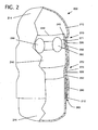
- FIG. 1 shows an illustrative conventional capsule 100 including a cap 110 and a body 140.
- Cap 110 includes an open end 112 and a closed end 114.
- body 140 includes an open end 142 and a closed end 144.
- Open end 142 of body 140 is of a slightly smaller diameter than open end 112 of cap 110 such that body 140 may be partially inserted into cap 110.
- a separation of cap 110 and body 140 is prevented by friction and/or various modifications of an exterior surface of body 140 and/or an opposed inner surface of cap 110.
- U.S. Patent No. 5,769,267 to Duynslager et al. which is hereby incorporated by reference, discloses a two-piece telescoping capsule having corresponding connection units on the cap part and body as well as protrusions on an inner surface of the cap part to increase friction between the cap part and the body.
- the containers are supplied to a filling apparatus in a "prelock" condition in which the body part is telescoped only partially into the cap.
- the two parts are separated in the filling machine and then fully closed after the filling operation.
- the parts may alternatively or additionally be sealed by various methods.
- such sealing includes the spraying with a liquid or dipping of the capsule parts in a liquid.
- Such liquid may itself provide adhesive and/or sealing properties.
- such liquid may result in the partial dissolution or disintegration of portions of the capsule parts, whereby the capsule parts are fused or sealed upon evaporation of the liquid.
- Illustrative liquid sealing methods and solutions are disclosed in U.S. Patent No. 4,893,721 to Bodenmann et al. , which is hereby incorporated by reference.
- the particular liquid chosen will depend, in part, upon the composition of the capsule parts, but may include, for example, water or an alcohol.
- Capsules may be constructed from a variety of film-forming agents such as gelatin, hydroxypropylmethylcellulose (HPMC), pullulan, etc.
- HPMC hydroxypropylmethylcellulose
- a number of defects have been observed in known devices, particularly deformations and microcracks in capsule walls. Deformations may result from a thinning and/or weakening of a capsule wall due to an excess of sealing fluid, which necessarily at least partially dissolves or disintegrates a material of the capsule wall.
- Microcracks generally take the form of small breaks or discontinuities and almost always appear near a locking structure cap, i.e., portions of the cap and body providing a friction fit to prevent opening of the capsule. Microcracks result from stresses upon the capsule parts combined with a locally low loss on drying (LOD), i.e., low moisture content, and thus brittleness. Stresses may result, for example, from an internal capsule pressure, e.g., from the closing and/or heating of the capsule, or stresses placed upon the capsule parts themselves due to the force required to insert the capsule body into the capsule cap.
- LOD locally low loss on drying
- the locally low LOD or brittleness may result, for example, from the presence of an alcohol vapor, which acts as a dehumidifier; in a gap between the cap and the body or from the drying of the capsule material, also attributable to an alcohol in the sealing fluid.
- an alcohol vapor which acts as a dehumidifier
- pullulan is particularly susceptible to these defects.
- Pullulan capsules experience higher than normal rates of failure after a sealing process, due, at least in part, to the fact that pullulan dissolves in room temperature water.
- Gelatin forms a phase intermediate between a solid and a liquid upon application of water, wherein the chain structure of the gelatin remains intact.
- pullulan transitions from a solid to a liquid.
- the strength of pullulan is lost locally near the sealing area.
- deformations may be common, resulting in the bending, swelling, or rupturing of capsules. Examples of failure include improper sealing, deformation, etc.
- current capsule designs are not well suited to allow for the liquid sealing of a pullulan-based multi-piece capsule.
- the invention includes a container comprising: a cap; a body slidably engagable inside the cap; and a fluid gap positioned between the cap and the body adjacent an end of the cap, wherein a first channel of the cap and a first channel of the body form a snap fit joint and a second channel of the cap and a second channel of the body form a fluid stop joint whereby a sealing fluid is substantially restricted to the fluid gap by the fluid stop joint.
- a first aspect of the invention provides a container comprising: a cap; a body slidably engagable inside the cap; and a fluid gap positioned between the cap and the body adjacent an end of the cap, wherein a first channel of the cap and a first channel of the body form a snap fit joint characterized as free of contact with a sealing fluid and a second channel of the cap and a second channel of the body form a fluid stop joint whereby a sealing fluid is substantially restricted to the fluid gap by the fluid stop joint.
- a second aspect of the invention provides a container comprising: a cap having a first channel and a second channel; a body slidably engagable inside the cap, the body having a first channel engagable with the first channel of the cap in a first position and the second channel of the cap in a second position, a second channel engagable with the second channel of the cap in the second position, and a third channel forming an entry gap adjacent an open end of the cap; and a fluid gap between the cap and the body adjacent an end of the cap.
- a third aspect of the invention provides a container comprising: a cap having a first channel and a second channel; a body slidably engagable inside the cap, the body having a first channel engagable with the first channel of the cap in a first position and the second channel of the cap in a second position, a second channel engagable with the second channel of the cap in the second position, and a third channel forming an entry gap adjacent an open end of the cap; a fluid gap positioned between the cap and the body adjacent an end of the cap; and a pressure release channel, wherein the first channel of the cap and the first channel of the body form a snap fit joint, the second channel of the cap and the second channel of the body form a fluid stop joint for substantially restricting sealing fluid to the fluid gap, and the pressure release channel is located substantiallly within the snap fit joint.
- a fourth aspect of the invention provides a container comprising: a cap having a first channel and a second channel; a body slidably engagable inside the cap, the body having a first channel engagable with the second channel of the cap and a second channel forming an entry gap adjacent an open end of the cap; and a fluid gap between the cap and the body adjacent an end of the cap, wherein the second channel of the cap and a portion of the body between an open end of the body and the first channel of the body form a pre-lock joint in a first position and the second channel of the cap and the first channel of the body form a fluid stop joint for substantially restricting a sealing fluid to the fluid gap in a second position.
- a fifth aspect of the invention provides a method of sealing a multi-part container comprising: providing a container having: a cap; a body slidably engagable inside the cap; and a fluid gap positioned between the cap and the body adjacent an end of the cap; closing the container such that a first channel of the cap and a first channel of the body are in contact and a second channel of the cap and a second channel of the body are in contact; applying a sealing fluid to the fluid gap; and drying the container.
- Container 200 comprises cap 210 and body 240.
- Each of cap 210 and body 240 includes an open end 212 and 242, respectively.
- Open end 212, 242 may be of any number of cross-sectional shapes, including, for example, circular, ovoid, hexagonal, or square. In one preferred embodiment, each open end 212, 242 is circular in cross-section.
- Open end 242 is of a slightly smaller diameter than open end 212, such that body 240 may be at least partially inserted into cap 210.
- open end 242 may include an inward taper 243 to facilitate insertion of body 240 into cap 210, although such a feature is not essential.
- each of cap 210 and body 240 includes a closed end 214, 244. While somewhat dependent upon the cross-sectional shape of the open end, a closed end may be of any number of shapes, including, for example, hemispherical or pyrimidal.
- the closed ends of cap 210 and body 240 may have the same or different shapes. In one preferred embodiment, each closed end is hemispherical in shape.
- cap 210 and body 240 at points between their open and closed ends may be different than the cross-sectional shapes at either their open ends or closed ends. That is, the cross-sectional shape of cap 210 and/or body 240 may change between their open ends and closed ends. However, since body 240 is ultimately to be at least partially inserted into cap 210, no cross-sectional shape of either should impede such insertion.
- container 200 includes a snap fit joint 270 comprising corresponding channels 220 and 250 on cap 210 and body 240, respectively.
- corresponding it is meant that channels 220, 250 are of compatible shape and size such that one may rest atop the other.
- channels 220, 250 need not be identical in shape or size.
- channel 220 may have a V-shape while channel 250 may have a U-shape.
- Channels 220, 250 are each preferably continuous along a circumference of cap 210 and body 240, respectively, although one or both may also be discontinuous or segmented.
- Snap fit joint 270 preferably includes a radially-oriented interference gap 271 between cap 210 and body 240 of between about 20 ⁇ m and about 60 ⁇ m, and more preferably about 40 ⁇ m.
- Snap fit joint 270 preferably has a height (i.e., a length along an axis of container 200) of between about 1/6 and about 1/2, and more preferably between about 1/5 and about 1/3 the height of container 200 when fully closed.
- a height of snap fit joint 272 would be between about 1 mm and about 5 mm, and more preferably between about 1.2 mm and about 2 mm. Other sizes may also be possible.
- a small amount of sealing fluid 290 may enter fluid gap 260, resulting in the partial dissolution or disintegration of a portion of cap 210 and body 240 and then a fusing of cap 210 and body 240 upon evaporation and/or removal of sealing fluid 290.
- the fusing of cap 210 and body 240 provides a seal that is tamperproof or tamper evident, i.e., opening container 200 after such fusing requires destruction of the seal.
- Fluid gap 260 preferably has a width, i.e., between an internal surface of cap 210 and an external surface of body 240, between about 20 ⁇ m and about 120 ⁇ m, and more preferably about 40 ⁇ m.
- Fluid gap 260 preferably has a height (i.e., a length along an axis of container 200) of between about 1/10 and about 1/3, and more preferably between about 1/8 and about 2/9 a height of container 200 when fully closed. For example, for a size 2 container 200 having a closed height of about 18 mm, fluid gap 260 preferably has a height between about 2 mm and about 5 mm, and more preferably about 3 mm and about 4 mm. Other sizes may also be possible.
- the volume of fluid gap 260 is smaller than analogous features of known devices. This smaller volume results in less sealing fluid 290 between cap 210 and body 240 and therefore less deformation of either cap 210 or body 240 following the sealing of container 200.
- Fluid gap 260 is preferably substantially uniform in width, i.e., cap 210 is preferably equally spaced from body 240 along a length of fluid gap 260.
- the uniformity of fluid gap 260 thus results in less sealing fluid 290 at the open end 212 of cap 210, as compared to the conical-shaped gaps of known devices, wherein the gap is greater nearer open end 112 ( FIG. 1 ) of cap 110 ( FIG. 1 ).
- container 200 may optionally further include a fluid stop joint 272 comprising corresponding channels 222 and 252 on cap 210 and body 240, respectively.
- Channels 222, 252 are each preferably continuous along a circumference of cap 210 and body 240, respectively, although one or both may also be discontinuous or segmented.
- Fluid stop joint 272 preferably includes a gap 273 between cap 210 and body 240 of between about -20 ⁇ m and about +10 ⁇ m, and more preferably about 0 ⁇ m.
- Fluid stop joint 272 preferably has a height (i.e., a length along an axis of container 200) of between about 1/90 and about 1/9, more preferably between about 1/26 and about 1/20, and most preferably about 1/21 a height of container 200 when fully closed.
- a height i.e., a length along an axis of container 200
- fluid stop joint 272 would have a height between about 0.2 mm and about 3.5 mm, more preferably between about 0.7 mm and about 0.9 mm, and most preferably about 0.86 mm.
- Other sizes may also be possible.
- container 200 includes both snap fit joint 270 and fluid stop joint 272.
- Such an arrangement uncouples the stress and brittleness (due to locally low LOD) defects of known devices. That is, rather than stress and brittleness affecting the same portion of container 200, a container 200 of this embodiment that includes both a snap fit joint 270 and a fluid stop joint 272 restricts stresses to snap fit joint 270 and eliminates or reduces brittleness by restricting sealing fluid 290 (and therefore alcohol vapors) to fluid gap 260.
- fluid stop joint 272 inhibits or stops the capillary action of sealing fluid 290, resulting in less sealing fluid 290 between cap 210 and body 240 and faster, more efficient drying of container 200.
- Container 200 may optionally further include one or more pressure release channels 280 on body 240 for allowing the escape of gas within container 200 upon the insertion of body 240 into cap 210.
- pressure release channel 280 comprises a depression within a surface of body 240.
- Pressure release channel 280 may have any number of cross-sectional shapes, including, for example, ovoid and circular.
- pressure release channel 280 is preferably ovoid in cross-section.
- pressure release channel 280 is located substantially within the area of snap fit joint 270 and is not located within fluid stop joint 272. Such an arrangement provides a particular advantage over known capsules when used in conjunction with snap fit joint 270 and fluid stop joint 272.
- pressure release channels permit gas to escape from a capsule during the drying process, wherein the capsule is heated.
- the escape of gas during this step causes the formation of gas channels within the sealing area, which compromise the integrity of the seal, permitting the leaking of capsule contents and/or failure of the seal.
- pressure release channel 280 By restricting pressure release channel 280 to the area of snap fit joint 270 and including fluid stop joint 272, gas is allowed to escape from within container 200 as it is closed but is prevented from escaping by fluid stop joint 272 once container 200 is fully closed. As such, gas does not escape from container 200 during the drying process and gas channels (not shown) do not form in the sealing area. The result is an uninterrupted seal providing increased strength and integrity.
- body 240 and/or cap 210 may be prevented or reduced by utilizing a body 240 and/or cap 210 of increased thickness.
- Known containers typically include caps and bodies having wall thicknesses of approximately 100 ⁇ m. Utilizing a cap and/or body having a wall thickness of approximately 130 ⁇ m has been shown to significantly decrease container deformation.
- FIGS. 3A-D s how cross-sectional views of various alternative embodiments of the invention having different cross-sectional shapes.
- the shapes of both cap 210 and body 240 are circular in FIG. 3A , ovoid in FIG. 3B , hexagonal in FIG. 3C , and square in FIG. 3D . It should be noted, of course, that cap 210 and body 240 may have different cross-sectional shapes, provided that the different shapes do not impede the insertion of body 240 into cap 210.
- container 200 further includes an additional channel 254 on body 240.
- Additional channel 254 may have dimensions similar to those of channels 220, 250 or channels 222, 252 and is preferably located adjacent open end 212 of cap 210. Such location of additional channel 254 results in an entry gap 262 between body 240 and open end 212 of cap 210. Entry gap 262 preferably has a width (i.e., a space between body 240 and cap 210) between about 90 ⁇ m and about 200 ⁇ m, more preferably between about 110 ⁇ m and 150 ⁇ m, and most preferably about 140 ⁇ m.
- the inclusion of additional channel 254 provides at least three advantages.
- entry gap 262 improves the capillary action of sealing fluid 290, drawing sealing fluid 290 into fluid gap 260.
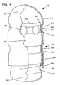
- FIG. 5 shows yet another alternative embodiment of a container 200 of the present invention, wherein open end 242 of body 240 is elongated such that open end 242 contacts an inner surface of cap 210 upon complete insertion of body 240 into cap 210.
- Open end 242 may still include inward taper 243.
- Elongated open end 242 provides a number of advantages over known designs. First, the formation of gas channels in sealing fluid 290, caused by the escape of gas from inside container 200 upon heating; is reduced or prevented. Second, internal pressure is substantially reduced following closing of container 200.
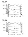
- FIGS. 6A-B two additional alternative embodiments of a container 200 of the present invention are shown in partial cross-section.
- a pillar 216 has been included on an inner surface 211 of cap 210 near open end 212.
- Such pillars 216 are preferably not continuous along inner surface 211 of cap 210, but rather are located periodically along inner surface 211.
- Such an arrangement results in "pillared areas," as on the left side of FIG. 6A and capillary channels 218 as on the right side of FIG. 6A .
- Pillar 216 significantly reduces a gap 261 between cap 210 and body 240 and effectively restricts fluid gap 260 to a location further from open end 212.
- fluid gap 260 preferably has a width between about 20 ⁇ m and about 120 ⁇ m, and more preferably about 40 ⁇ m.
- pillar 216 preferably changes this width to between an interference of about 30 ⁇ m and a gap of about 5 ⁇ m, and preferably to an interference of about 25 ⁇ m.
- the inclusion of one or more such pillars provides a number of benefits over known designs. First, pillars 216 result in less total sealing fluid 290 at open end 212, resulting in less dissolution or disintegration and therefore less deformation at open end 212. Second, where pillars 216 are located, little or no sealing fluid 290 is present at open end 212.
- pillars 216 increase the strength of cap 210, specifically, and container 200, generally, in an area that is typically the weakest location in known designs.
- the capillary channels 218 formed between pillars 216 enhance the capillary action of sealing fluid 290, drawing it further into fluid gap 260.
- Pillar(s) 216 is/are located further inwardly from open end 212. Such an arrangement provides the increased strength noted above while permitting more sealing fluid 290 immediately beneath open end 212 than the embodiment in FIG. 6A . Such an arrangement may be beneficial, for example, where a stronger seal is required at open end 212. Pillars 216 may similarly be located elsewhere along an inner surface of cap 210 or an exterior surface of body 240 where increased strength, increased friction, and/or reduced sealing fluid are desirable, such as within fluid stop joint 272 ( FIGS. 2-4 ).
- FIG. 6C shows a cross-sectional view of a particularly preferred embodiment, wherein container 200 includes a plurality of evenly-spaced pillars 216 on the inner surface 211 of cap 210, forming a plurality of evenly-spaced capillary channels 218. Most preferably, container 200 includes six evenly-spaced pillars 216, as shown. Gap 261 between each pillar 216 and body 240 is significantly reduced as compared to fluid gap 260. It should be recognized that one or more pillars 216 may similarly be located on an exterior surface 241 of body 240.
- FIG. 7 shows an embodiment of the present invention in such a prelock condition.
- body 240 is telescopically inserted into cap 210 to the point at which channel 250 of body 240, which corresponds to channel 220 of cap 210 when container 200 is fully closed, contacts channel 222 of cap 210. That is, when inserted to the prelock position, the channel of body 240 that ultimately makes up part of snap fit joint 270 is instead inserted only as far as channel 222, the cap 210 component of fluid stop joint 272.
- Other prelock positions are possible, of course.
- body 240 may be inserted into cap 210 such that channel 222 of cap 210 contacts an exterior surface (rather than channel 250) of body 240.
- the force necessary to disassociate cap 210 and body 240 from the prelock position may be reduced compared to known devices. This decrease in required force is attributable, in part, to the uncoupling of the stress and fluid stop functions noted above.
- known devices typically utilize a single joint to both secure the cap and body and limit the egress of a sealing fluid, those functions are separate in an embodiment of the present invention having both a snap fit joint 270 and a fluid stop joint 272.
- channels making up snap fit joint 270 and fluid stop joint 272 may be adjusted such that an interaction of channels 222 and 250, as shown in FIG. 7 , is a more loose connection than that resulting from the interaction of channels 220 and 250 and/or channels 222 and 252, as shown in FIGS. 2-4 .
- the result in a particularly preferred embodiment, is a container 200 with a lower prelock strength, as compared to known devices.
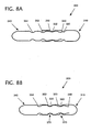
- FIGS. 8A-B show cross-sectional side views of a capsule 300 according to an alternative embodiment of the invention in a prelock and closed configuration, respectively.
- body 340 is shown having three channels: first channel 350, second channel 352, and third channel 354, similar to the arrangement shown in FIGS. 4-5 .
- first channel 350 is both higher and shallower than shown in FIGS. 4-5 .
- Cap 310 includes a first channel 320 and second channel 322. As shown in FIGS. 8A-B , first channel 320 of cap 310 is substantially triangular in cross-section, although this is not essential.
- first channel 350 of body 340 results in a looser connection between first channel 350 of body 340 and second channel 322 of cap 310 when in a prelock position, such as that shown in FIG. 8A .
- an interference between body 340 and second channel 322 of cap 310 is between about -20 ⁇ m and about 50 ⁇ m, preferably between about -10 ⁇ m and 30 ⁇ m, and most preferably about 19 ⁇ m.
- a force required to remove cap 310 from body 340, when in a prelock position such as that shown in FIG. 8A is preferably between about 5 grams and about 55 grams, preferably between about 5 grams and about 40 grams, and most preferably between about 10 grams and about 30 grams (as an average from a measurement of 10 parts).
- capsule 300 is shown in a closed position, wherein first channel 320 of cap 310 and first channel 350 of body 340 form a snap fit joint 370 and second channel 322 of cap 310 and second channel 352 of body 340 form a fluid stop joint 372.
- snap fit joint 370 includes an interference between cap 310 and body 340 of between about -20 ⁇ m and about 60 ⁇ m, and more preferably about 40 ⁇ m.
- FIGS. 9A-B show cross-sectional side views of a capsule 400 according to another alternative embodiment of the invention.
- body 440 contains only two channels 452, 454.
- the first channel 350 (FIGS. 8A-B ) has been removed.
- second channel 422 of cap 410 rests not within a channel, as in the embodiments described above, but adjacent a portion of body 440 between channel 452 and the inner taper 443 of the open end of body 440.
- open ends of cap 410 and/or body 440 may be deflected due to frictional contact in the prelock position. The degree of such deflection will depend, in part, upon the rigidities of cap 410 and body 440 and the degree of frictional contact therebetween.
- an interference between second channel 422 of cap 410 and body 440 is between about 5 ⁇ m and about 80 ⁇ m, preferably between about 0 ⁇ m and 30 ⁇ m, and most preferably about 19 ⁇ m.
- a force required to remove cap 410 from body 440, when in a prelock position such as that shown in FIG. 9A is preferably between about 5 grams and about 55 grams, preferably between about 5 grams and about 40 grams, and most preferably between about 10 grams and about 30 grams (as an average from a measurement of 10 parts).
- second channel 422 of cap 410 rests within channel 452 of body 440, forming fluid stop joint 472, as in the embodiments described above.
- snap fit joint 470 is formed by channel 420 of cap 410 deflecting and being deflected by a portion of body 440 between first channel 452 and inward taper 443. The degree of such deflection will depend, in part, upon the rigidities of cap 410 and body 440 and the amount of frictional contact therebetween. However, in general, less force is required to remove cap 410 from body 440 in the closed position of FIG. 9B than in the embodiments described above.
- Snap fit joint 470 includes an interference between cap 410 and body 440 of between about -20 ⁇ m and about 80 ⁇ m, and more preferably about 40 ⁇ m.
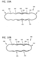
- body 540 includes three channels: first channel 550, second channel 552, and thrid channel 554.
- second channel 552 of body 540 is both higher and shallower than first channel 550 of body 540.
- second channel 522 of cap is both higher and shallower than first channel 520 of cap 510 and, more importantly, is both higher and shallower than first channel 550 of body 540.
- second channel 522 of cap 510 does not rest within first channel 550 of body 540.
- a force required to remove cap 510 from body 540, when in a prelock position such as that shown in FIG. 10A is preferably between about 5 grams and about 55 grams, preferably between about 5 grams and about 40 grams, and most preferably between about 10 grams and about 30 grams (as an average from a measurement of 10 parts).
- FIG. 10B shows capsule 500 in a closed position.
- first channel 520 of cap 510 and first channel 550 of body 540 are similar in shape, as are second channel 522 of cap 510 and second channel 552 of body 540.
- snap fit joint 570 and fluid stop joint 572 are formed as in the embodiments of FIGS. 2 , 4 , 5 , 7 , and 8A-B, with correspondingly-shaped channels in the cap and body and unlike the embodiment of FIGS. 9A-B .
- the force required to remove cap 510 from body 540 in the closed position of FIG. 10B is higher than in the embodiment of FIG. 9B .
- FIGS. 11 A-B show cross-sectional side views of yet another alternative embodiment of a capsule 600 according to the invention.
- Body 640 includes two channels: first channel 650 and second channel 652.
- second channel 652 includes a first portion 652A having a first depth and a second portion 652B having a second depth less than the first depth.
- First portion 652A is located closer to an open end of body 640 than is second portion 652B.
- FIG. 11 A shows capsule 600 in a prelock position, wherein second channel 622 of cap 610 rests within first channel 650 of body 640.
- FIG. 11 B shows capsule 600 in a closed position, wherein first channel 620 of cap 610 rests within first channel 650 of body 640, forming snap fit ring 670, and second channel 622 of cap 610 rests within second channel 652 of body 640, forming fluid stop ring 672. More specifically, second channel 622 of cap 610 rests within first portion 652A of second channel 652 of body 640. In such an arrangement, second portion 652B provides a void beneath an open end of cap 610, into which a quantity of sealing fluid (not shown) may be contained. Capsule 600 is, therefore, particularly advantageous in ensuring adequate sealing of capsule 600 using a sealing fluid.
- cap and/or body walls can result in the cap and body touching at areas adjacent an open end of the cap, thereby preventng the entry of sealing fluid beneath the cap and providing a thorough seal.
- second portion 652B an adequate seal is ensured by the provision of a void beneath an open end of cap 610 into which the sealing fluid may enter.
- first and second channels on one or both of a cap and body may be applied to any number of capsule arrangements.
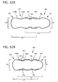
- U.S. Patent No. 4,893,721 to Bodenmann et al. which is hereby incorporated by reference, describes a tamperproof capsule having a cap and a body of approximately the same length, the diameter of each being substantially less than its length.
- FIGS. 12A-B show a capsule 700 according to such an embodiment.
- cap 710 and body 740 are shown in a prelock position.
- Cap 710 has a length L1 approximately equal to a length L2 of body 740.
- each of L1 and L2 is greater than the diameters of cap 710, D1, and body 740, D2.
- D2 is necessarily equal to or slightly less than D1.
- cap 710 and body 740 of capsule 700 are shown in a closed position, wherein the similarities in length of L1 and L2 are more clearly observable.
- the cap and body may be comprised of any number of materials known in the art including, for example, gelatin, hydroxypropylmethylcellulose, polyvinyl alcohol, hydroxypropyl starch, and pullulan. Pullulan is a particularly preferred material.
- the cap and body may each be comprised of more than one material and may each be of different materials or combinations of materials.
- the cap and the body may be further sealed using a sealing fluid 290 ( FIGS. 2-5B) capable of at least partially dissolving and/or disintegrating a portion of the cap and/or body.
- a sealing fluid 290 FIGS. 2-5B
- Any sealing fluid known in the art may be used, based upon the composition of the cap and body.
- a preferred sealing fluid contains at least one of water and an alcohol.
- a particularly preferred sealing fluid contains water and ethanol. As described below with respect to FIG. 13 , excess sealing fluid may be removed by evaporation or suction.
- a flow diagram is shown of a method of filling and sealing a container of the present invention.
- a container according to one embodiment of the present invention is provided in a prelock position, such as that shown in FIGS. 7 , 8A , 9A , 10A , 11 A, and 12A .
- the container may be of any number of shapes and configurations, including those of the embodiments described above.
- the container is opened such that cap 210 ( FIG. 7 ) and body 240 ( FIG. 7 ) are not in contact.
- a substance may be added to either or both of cap 210 ( FIG. 7 ) and body 240 ( FIG. 7 ) at step S3.
- the container of the present invention may be used to contain any number of substances to be delivered to an individual, including, for example, a pharmaceutical, a medicine, or a vitamin.
- the substance may take one or more of a number of forms, including, for example, a powder, a liquid, or a solid.
- the substance is added only to body 240 ( FIG. 7 ).
- the container is closed, whereby body 240 is inserted into cap 210, as shown, for example, in FIG. 2 .
- a sealing fluid 290 FIG. 2
- Sealing fluid at least partially dissolves and/or disintegrates at least one of the cap and the body.
- excess sealing fluid is optionally removed. Such removal may be accomplished, for example, by the application of a suction force to the container.
- the container is dried to substantially remove any remaining sealing fluid and fuse the at least partially dissolved and/or disintegrated portions of the cap and the body.
- the drying step may include, for example, heating the container. When heating is employed in the drying step, the container is preferably heated to between about 35 oC and about 55 oC.
- a container of the present invention may be provided in an open rather than a prelock position. As such, step S2 is unnecessary. Similarly, a container of the present invention may be provided in a closed position with a substance already contained therein. As such, steps S2 through S4 are unnecessary.
Landscapes
- Health & Medical Sciences (AREA)
- Chemical & Material Sciences (AREA)
- Medicinal Chemistry (AREA)
- Pharmacology & Pharmacy (AREA)
- Life Sciences & Earth Sciences (AREA)
- Animal Behavior & Ethology (AREA)
- General Health & Medical Sciences (AREA)
- Public Health (AREA)
- Veterinary Medicine (AREA)
- Closures For Containers (AREA)
- Medical Preparation Storing Or Oral Administration Devices (AREA)
- Medicinal Preparation (AREA)
Applications Claiming Priority (4)
| Application Number | Priority Date | Filing Date | Title |
|---|---|---|---|
| US70660405P | 2005-08-09 | 2005-08-09 | |
| US11/485,686 US20070036830A1 (en) | 2005-08-09 | 2006-07-13 | Container |
| US11/498,402 US8377471B2 (en) | 2005-08-09 | 2006-08-03 | Container |
| PCT/IB2006/002136 WO2007017725A2 (en) | 2005-08-09 | 2006-08-04 | Container |
Publications (2)
| Publication Number | Publication Date |
|---|---|
| EP1915121A2 EP1915121A2 (en) | 2008-04-30 |
| EP1915121B1 true EP1915121B1 (en) | 2013-10-02 |
Family
ID=46045543
Family Applications (1)
| Application Number | Title | Priority Date | Filing Date |
|---|---|---|---|
| EP06795209.3A Active EP1915121B1 (en) | 2005-08-09 | 2006-08-04 | Container |
Country Status (11)
| Country | Link |
|---|---|
| US (1) | US8377471B2 (zh) |
| EP (1) | EP1915121B1 (zh) |
| JP (3) | JP4422779B2 (zh) |
| KR (1) | KR100974979B1 (zh) |
| CN (2) | CN101237847B (zh) |
| AU (1) | AU2006277727B2 (zh) |
| BR (1) | BRPI0614735B8 (zh) |
| CA (1) | CA2617967C (zh) |
| ES (1) | ES2436015T3 (zh) |
| MX (1) | MX2008001043A (zh) |
| WO (1) | WO2007017725A2 (zh) |
Families Citing this family (18)
| Publication number | Priority date | Publication date | Assignee | Title |
|---|---|---|---|---|
| JP5667874B2 (ja) * | 2007-10-19 | 2015-02-12 | ファイザー・プロダクツ・インク | マルチコンパートメント容器 |
| EP2232700B1 (en) | 2007-12-21 | 2014-08-13 | Dts Llc | System for adjusting perceived loudness of audio signals |
| AU2009247656A1 (en) * | 2008-05-12 | 2009-11-19 | Capsugel Belgium Nv | Improved capsule with air-vents |
| IT1393245B1 (it) * | 2008-07-24 | 2012-04-12 | Universita' Degli Studi Di Milano | Forme farmaceutiche per il rilascio tempo-specifico di farmaci |
| US8538042B2 (en) | 2009-08-11 | 2013-09-17 | Dts Llc | System for increasing perceived loudness of speakers |
| EP2777802B1 (en) | 2013-12-03 | 2016-03-16 | Capsugel Belgium NV | Multi-compartment dosage form articles |
| EP3076954B1 (en) | 2013-12-03 | 2020-09-23 | Capsugel Belgium NV | Dosage form articles with multiple compartments |
| EP3167867A1 (en) | 2015-11-16 | 2017-05-17 | Capsugel Belgium NV | Tamperproof dosage form |
| EP3167868A1 (en) | 2015-11-16 | 2017-05-17 | Capsugel Belgium NV | Tamperproof dosage form |
| EP3167870B1 (en) * | 2015-11-16 | 2024-01-03 | Capsugel Belgium NV | Tamperproof oral dosage form |
| EP3167869A1 (en) * | 2015-11-16 | 2017-05-17 | Capsugel Belgium NV | Tamperproof oral dosage form |
| EP3219300B1 (en) | 2016-03-15 | 2019-06-19 | Capsugel Belgium NV | Aseptic hard capsule sealing apparatus and methods |
| JP2019535818A (ja) | 2016-10-27 | 2019-12-12 | コンボキャップ インコーポレイテッド | 可食カプセルならびにこれを製造するための方法および装置 |
| US10729619B2 (en) * | 2017-05-03 | 2020-08-04 | Garry Tsaur | Capsule sealing composition and its sealing method thereof |
| US11083738B2 (en) | 2017-09-28 | 2021-08-10 | Natals, Inc. | Dietary nutrient compositions |
| EP3607931B1 (de) * | 2018-08-07 | 2023-03-29 | Harro Höfliger Verpackungsmaschinen GmbH | Kapselverschliesseinrichtung zum verschliessen zweiteiliger kapseln |
| JP2023516370A (ja) * | 2020-03-02 | 2023-04-19 | クラフト ヘルス プライベート リミテッド | 持続的薬物放出のための経口剤形 |
| CN112353776B (zh) * | 2020-11-18 | 2022-08-16 | 湖北灵铠智能装备有限公司 | 一种改良型胶囊及封装方法 |
Family Cites Families (41)
| Publication number | Priority date | Publication date | Assignee | Title |
|---|---|---|---|---|
| US2718980A (en) * | 1951-10-02 | 1955-09-27 | Robinson William H | Container seal |
| US3399803A (en) * | 1966-10-11 | 1968-09-03 | Parke Davis & Co | Self-locking medicament capsule |
| US3508678A (en) * | 1968-04-29 | 1970-04-28 | Parke Davis & Co | Locking capsule |
| US3584759A (en) * | 1969-06-19 | 1971-06-15 | Scherer Ltd G C | Separation-resistant capsule |
| US3702653A (en) * | 1970-09-14 | 1972-11-14 | Parke Davis & Co | Package means |
| US3664495A (en) * | 1970-12-21 | 1972-05-23 | Parke Davis & Co | Locking capsule |
| DE7203269U (de) * | 1972-01-29 | 1972-04-27 | Agfa-Gevaert Ag | Anklebevorrichtung fuer folienbahnen |
| US3823843A (en) * | 1972-10-26 | 1974-07-16 | Lilly Co Eli | Locking capsule |
| US3927195A (en) * | 1974-01-31 | 1975-12-16 | Lilly Industries Ltd | Production of capsules |
| US4040536A (en) * | 1975-05-05 | 1977-08-09 | R. P. Scherer Corporation | Locking hard gelatin capsule |
| NL7803330A (nl) * | 1977-03-29 | 1978-10-03 | Capsugel Ag | Sluitcapsule gevuld met viskeus materiaal, in het bijzonder een vloeibaar farmaceutisch preparaat, en werkwijze voor het vervaardigen van een dergelijke capsule. |
| DE2722822C2 (de) * | 1977-05-20 | 1984-11-08 | Capsugel AG, Basel | Verfahren zum Herstellen einer zum Aufnehmen eines viskosen Stoffes, insbesondere eines flüssigen Arzneimittels, geeigneten Steckkapsel |
| DE2722807A1 (de) * | 1977-05-20 | 1978-11-23 | Capsugel Ag | Verfahren zum herstellen einer mit viskosem stoff gefuellten steckkapsel |
| DE2722806C2 (de) * | 1977-05-20 | 1984-12-13 | Capsugel AG, Basel | Kapselkörper für eine Steckkapsel für Arzneimittel oder andere portionsweise zu verpackende Stoffe, sowie Verfahren zu seiner Herstellung |
| JPS5423117A (en) | 1977-07-25 | 1979-02-21 | Takeda Chem Ind Ltd | Hard capsule |
| US4281763A (en) * | 1979-10-31 | 1981-08-04 | Pace Joseph A | Two-piece hardshell, soluble and digestible liquid containing gelatin capsule |
| US4442941A (en) * | 1982-01-11 | 1984-04-17 | Key Pharmaceuticals, Inc. | Anti-spilling drug capsule |
| EP0110500B1 (en) * | 1982-10-29 | 1987-06-03 | Warner-Lambert Company | Tamper-resistant capsules |
| US4478658A (en) * | 1982-12-20 | 1984-10-23 | Warner-Lambert Company | Method for sealing non-enteric capsules |
| US4656066A (en) * | 1982-12-20 | 1987-04-07 | Warner-Lambert Company | Apparatus and method for sealing capsules |
| US4487327A (en) * | 1982-12-21 | 1984-12-11 | Grayson Robert E | Locking capsule |
| US4539060A (en) * | 1983-02-18 | 1985-09-03 | Warner-Lambert Company | Apparatus and method of sealing capsules |
| US4534467A (en) * | 1983-02-24 | 1985-08-13 | Rathbun Daniel L | Tamperproof capsule |
| US4543138A (en) * | 1983-07-07 | 1985-09-24 | Eli Lilly & Company | Capsule-sealing method and apparatus |
| US4576284A (en) * | 1983-12-02 | 1986-03-18 | Warner-Lambert Company | Closing of filled capsules |
| US4601896A (en) * | 1984-03-21 | 1986-07-22 | Mark Nugent | Pharmaceutical capsule compositions and structures for gastric sensitive materials |
| US4609417A (en) * | 1984-03-26 | 1986-09-02 | Microdry Corporation | Capsule sealer and method of sealing |
| US4667498A (en) * | 1984-06-29 | 1987-05-26 | Sauter Manufacturing Corp. | Method and apparatus of making gelatine capsule forming pins having a rounded locking groove |
| GB2172569A (en) | 1985-03-21 | 1986-09-24 | Warner Lambert Co | Improved capsule construction |
| IE58468B1 (en) * | 1984-10-25 | 1993-09-22 | Warner Lambert Co | Method for sealing capsules and capsule |
| GB2172570B (en) | 1985-03-21 | 1989-06-21 | Warner Lambert Co | Hard gelatin capsules. |
| CN1003578B (zh) * | 1984-10-25 | 1989-03-15 | 沃纳·兰伯特公司 | 改进的胶囊形状 |
| US4554034A (en) * | 1984-11-15 | 1985-11-19 | Battelle Memorial Institute | Bonding capsules |
| US5074426A (en) * | 1986-11-13 | 1991-12-24 | Warner-Lambert Company | Dividable capsule |
| KR890003520Y1 (ko) * | 1986-12-20 | 1989-05-27 | 주식회사 서흥캅셀 | 의약용 캅셀 |
| US4724019A (en) * | 1987-03-20 | 1988-02-09 | Warner-Lambert Company | Method and apparatus for sealing capsules |
| GB9223172D0 (en) * | 1992-11-05 | 1992-12-16 | Scherer Corp R P | Capsule construction |
| KR0124764Y1 (ko) * | 1995-09-23 | 1998-09-15 | 양주환 | 의약 및 식품용 하드 공 캅셀 |
| US5769267A (en) * | 1995-11-09 | 1998-06-23 | Warner-Lambert Company | Container |
| DE19835346A1 (de) * | 1998-08-05 | 2000-02-10 | Boehringer Ingelheim Pharma | Zweiteilige Kapsel zur Aufnahme von pharmazeutischen Zubereitungen für Pulverinhalatoren |
| EP1072245A1 (en) * | 1999-07-30 | 2001-01-31 | Warner-Lambert Company | Method and apparatus for sealing capsules and capsules suitable for use in said method and apparatus |
-
2006
- 2006-08-03 US US11/498,402 patent/US8377471B2/en active Active
- 2006-08-04 KR KR1020087003075A patent/KR100974979B1/ko not_active IP Right Cessation
- 2006-08-04 JP JP2008525654A patent/JP4422779B2/ja active Active
- 2006-08-04 BR BRPI0614735A patent/BRPI0614735B8/pt active IP Right Grant
- 2006-08-04 CA CA2617967A patent/CA2617967C/en active Active
- 2006-08-04 CN CN2006800289918A patent/CN101237847B/zh not_active Expired - Fee Related
- 2006-08-04 MX MX2008001043A patent/MX2008001043A/es active IP Right Grant
- 2006-08-04 ES ES06795209T patent/ES2436015T3/es active Active
- 2006-08-04 WO PCT/IB2006/002136 patent/WO2007017725A2/en active Application Filing
- 2006-08-04 CN CN201210011817.XA patent/CN102525816B/zh active Active
- 2006-08-04 AU AU2006277727A patent/AU2006277727B2/en not_active Ceased
- 2006-08-04 EP EP06795209.3A patent/EP1915121B1/en active Active
-
2009
- 2009-08-19 JP JP2009190251A patent/JP5006913B2/ja active Active
-
2011
- 2011-10-18 JP JP2011229263A patent/JP2012071141A/ja active Pending
Also Published As
| Publication number | Publication date |
|---|---|
| BRPI0614735B1 (pt) | 2018-02-14 |
| WO2007017725A2 (en) | 2007-02-15 |
| EP1915121A2 (en) | 2008-04-30 |
| KR100974979B1 (ko) | 2010-08-09 |
| JP4422779B2 (ja) | 2010-02-24 |
| US20070184077A1 (en) | 2007-08-09 |
| KR20080031056A (ko) | 2008-04-07 |
| CN102525816B (zh) | 2014-12-17 |
| JP2009504219A (ja) | 2009-02-05 |
| AU2006277727B2 (en) | 2009-10-29 |
| BRPI0614735A2 (pt) | 2011-04-12 |
| JP2012071141A (ja) | 2012-04-12 |
| CN101237847B (zh) | 2012-03-14 |
| WO2007017725A3 (en) | 2007-04-19 |
| BRPI0614735B8 (pt) | 2021-06-22 |
| JP2010000371A (ja) | 2010-01-07 |
| CN102525816A (zh) | 2012-07-04 |
| ES2436015T3 (es) | 2013-12-26 |
| CA2617967C (en) | 2011-02-01 |
| US8377471B2 (en) | 2013-02-19 |
| MX2008001043A (es) | 2008-03-19 |
| AU2006277727A1 (en) | 2007-02-15 |
| CA2617967A1 (en) | 2007-02-15 |
| JP5006913B2 (ja) | 2012-08-22 |
| CN101237847A (zh) | 2008-08-06 |
Similar Documents
| Publication | Publication Date | Title |
|---|---|---|
| EP1915121B1 (en) | Container | |
| JP2009504219A5 (zh) | ||
| US20070036830A1 (en) | Container | |
| AU718754B2 (en) | Two-chamber cartridge for propellant-free metered aerosols | |
| JP4416732B2 (ja) | 容器 | |
| JP6833730B2 (ja) | 接続及び容器システム | |
| EP2186748B1 (de) | Deckel mit einem behälter zum autonomen mischen | |
| CA2722271C (en) | Improved capsule with air-vents | |
| CN105705142A (zh) | 具有内部隔膜的胶囊 | |
| JP3342933B2 (ja) | 完全取出式容器及び方法 | |
| US20110097397A1 (en) | Break resistant gel capsule | |
| CN112353776B (zh) | 一种改良型胶囊及封装方法 | |
| JP7399874B2 (ja) | 方法と装置 | |
| ITGE950058A1 (it) | Tappo a rottura chiudibile mediante un tappo di protezione. |
Legal Events
| Date | Code | Title | Description |
|---|---|---|---|
| PUAI | Public reference made under article 153(3) epc to a published international application that has entered the european phase |
Free format text: ORIGINAL CODE: 0009012 |
|
| 17P | Request for examination filed |
Effective date: 20080310 |
|
| AK | Designated contracting states |
Kind code of ref document: A2 Designated state(s): AT BE BG CH CY CZ DE DK EE ES FI FR GB GR HU IE IS IT LI LT LU LV MC NL PL PT RO SE SI SK TR |
|
| AX | Request for extension of the european patent |
Extension state: HR |
|
| RAP1 | Party data changed (applicant data changed or rights of an application transferred) |
Owner name: CAPSUGEL BELGIUM NV |
|
| RAX | Requested extension states of the european patent have changed |
Extension state: HR Payment date: 20080310 |
|
| 17Q | First examination report despatched |
Effective date: 20121106 |
|
| GRAP | Despatch of communication of intention to grant a patent |
Free format text: ORIGINAL CODE: EPIDOSNIGR1 |
|
| GRAS | Grant fee paid |
Free format text: ORIGINAL CODE: EPIDOSNIGR3 |
|
| GRAA | (expected) grant |
Free format text: ORIGINAL CODE: 0009210 |
|
| AK | Designated contracting states |
Kind code of ref document: B1 Designated state(s): AT BE BG CH CY CZ DE DK EE ES FI FR GB GR HU IE IS IT LI LT LU LV MC NL PL PT RO SE SI SK TR |
|
| AX | Request for extension of the european patent |
Extension state: HR |
|
| REG | Reference to a national code |
Ref country code: GB Ref legal event code: FG4D |
|
| REG | Reference to a national code |
Ref country code: AT Ref legal event code: REF Ref document number: 634242 Country of ref document: AT Kind code of ref document: T Effective date: 20131015 Ref country code: CH Ref legal event code: EP |
|
| REG | Reference to a national code |
Ref country code: IE Ref legal event code: FG4D |
|
| REG | Reference to a national code |
Ref country code: DE Ref legal event code: R096 Ref document number: 602006038698 Country of ref document: DE Effective date: 20131128 |
|
| REG | Reference to a national code |
Ref country code: NL Ref legal event code: T3 |
|
| REG | Reference to a national code |
Ref country code: ES Ref legal event code: FG2A Ref document number: 2436015 Country of ref document: ES Kind code of ref document: T3 Effective date: 20131226 |
|
| REG | Reference to a national code |
Ref country code: AT Ref legal event code: MK05 Ref document number: 634242 Country of ref document: AT Kind code of ref document: T Effective date: 20131002 |
|
| PG25 | Lapsed in a contracting state [announced via postgrant information from national office to epo] |
Ref country code: SI Free format text: LAPSE BECAUSE OF FAILURE TO SUBMIT A TRANSLATION OF THE DESCRIPTION OR TO PAY THE FEE WITHIN THE PRESCRIBED TIME-LIMIT Effective date: 20131002 |
|
| REG | Reference to a national code |
Ref country code: LT Ref legal event code: MG4D |
|
| PG25 | Lapsed in a contracting state [announced via postgrant information from national office to epo] |
Ref country code: FI Free format text: LAPSE BECAUSE OF FAILURE TO SUBMIT A TRANSLATION OF THE DESCRIPTION OR TO PAY THE FEE WITHIN THE PRESCRIBED TIME-LIMIT Effective date: 20131002 Ref country code: IS Free format text: LAPSE BECAUSE OF FAILURE TO SUBMIT A TRANSLATION OF THE DESCRIPTION OR TO PAY THE FEE WITHIN THE PRESCRIBED TIME-LIMIT Effective date: 20140202 Ref country code: LT Free format text: LAPSE BECAUSE OF FAILURE TO SUBMIT A TRANSLATION OF THE DESCRIPTION OR TO PAY THE FEE WITHIN THE PRESCRIBED TIME-LIMIT Effective date: 20131002 Ref country code: CZ Free format text: LAPSE BECAUSE OF FAILURE TO SUBMIT A TRANSLATION OF THE DESCRIPTION OR TO PAY THE FEE WITHIN THE PRESCRIBED TIME-LIMIT Effective date: 20131002 Ref country code: SE Free format text: LAPSE BECAUSE OF FAILURE TO SUBMIT A TRANSLATION OF THE DESCRIPTION OR TO PAY THE FEE WITHIN THE PRESCRIBED TIME-LIMIT Effective date: 20131002 |
|
| PG25 | Lapsed in a contracting state [announced via postgrant information from national office to epo] |
Ref country code: CY Free format text: LAPSE BECAUSE OF FAILURE TO SUBMIT A TRANSLATION OF THE DESCRIPTION OR TO PAY THE FEE WITHIN THE PRESCRIBED TIME-LIMIT Effective date: 20131002 Ref country code: AT Free format text: LAPSE BECAUSE OF FAILURE TO SUBMIT A TRANSLATION OF THE DESCRIPTION OR TO PAY THE FEE WITHIN THE PRESCRIBED TIME-LIMIT Effective date: 20131002 Ref country code: LV Free format text: LAPSE BECAUSE OF FAILURE TO SUBMIT A TRANSLATION OF THE DESCRIPTION OR TO PAY THE FEE WITHIN THE PRESCRIBED TIME-LIMIT Effective date: 20131002 Ref country code: PL Free format text: LAPSE BECAUSE OF FAILURE TO SUBMIT A TRANSLATION OF THE DESCRIPTION OR TO PAY THE FEE WITHIN THE PRESCRIBED TIME-LIMIT Effective date: 20131002 |
|
| PG25 | Lapsed in a contracting state [announced via postgrant information from national office to epo] |
Ref country code: PT Free format text: LAPSE BECAUSE OF FAILURE TO SUBMIT A TRANSLATION OF THE DESCRIPTION OR TO PAY THE FEE WITHIN THE PRESCRIBED TIME-LIMIT Effective date: 20140203 |
|
| REG | Reference to a national code |
Ref country code: DE Ref legal event code: R097 Ref document number: 602006038698 Country of ref document: DE |
|
| PG25 | Lapsed in a contracting state [announced via postgrant information from national office to epo] |
Ref country code: EE Free format text: LAPSE BECAUSE OF FAILURE TO SUBMIT A TRANSLATION OF THE DESCRIPTION OR TO PAY THE FEE WITHIN THE PRESCRIBED TIME-LIMIT Effective date: 20131002 |
|
| PLBE | No opposition filed within time limit |
Free format text: ORIGINAL CODE: 0009261 |
|
| STAA | Information on the status of an ep patent application or granted ep patent |
Free format text: STATUS: NO OPPOSITION FILED WITHIN TIME LIMIT |
|
| PG25 | Lapsed in a contracting state [announced via postgrant information from national office to epo] |
Ref country code: RO Free format text: LAPSE BECAUSE OF FAILURE TO SUBMIT A TRANSLATION OF THE DESCRIPTION OR TO PAY THE FEE WITHIN THE PRESCRIBED TIME-LIMIT Effective date: 20131002 Ref country code: SK Free format text: LAPSE BECAUSE OF FAILURE TO SUBMIT A TRANSLATION OF THE DESCRIPTION OR TO PAY THE FEE WITHIN THE PRESCRIBED TIME-LIMIT Effective date: 20131002 |
|
| 26N | No opposition filed |
Effective date: 20140703 |
|
| PG25 | Lapsed in a contracting state [announced via postgrant information from national office to epo] |
Ref country code: DK Free format text: LAPSE BECAUSE OF FAILURE TO SUBMIT A TRANSLATION OF THE DESCRIPTION OR TO PAY THE FEE WITHIN THE PRESCRIBED TIME-LIMIT Effective date: 20131002 |
|
| REG | Reference to a national code |
Ref country code: DE Ref legal event code: R097 Ref document number: 602006038698 Country of ref document: DE Effective date: 20140703 |
|
| PG25 | Lapsed in a contracting state [announced via postgrant information from national office to epo] |
Ref country code: MC Free format text: LAPSE BECAUSE OF FAILURE TO SUBMIT A TRANSLATION OF THE DESCRIPTION OR TO PAY THE FEE WITHIN THE PRESCRIBED TIME-LIMIT Effective date: 20131002 Ref country code: LU Free format text: LAPSE BECAUSE OF FAILURE TO SUBMIT A TRANSLATION OF THE DESCRIPTION OR TO PAY THE FEE WITHIN THE PRESCRIBED TIME-LIMIT Effective date: 20140804 |
|
| REG | Reference to a national code |
Ref country code: CH Ref legal event code: PL |
|
| PG25 | Lapsed in a contracting state [announced via postgrant information from national office to epo] |
Ref country code: LI Free format text: LAPSE BECAUSE OF NON-PAYMENT OF DUE FEES Effective date: 20140831 Ref country code: CH Free format text: LAPSE BECAUSE OF NON-PAYMENT OF DUE FEES Effective date: 20140831 |
|
| REG | Reference to a national code |
Ref country code: IE Ref legal event code: MM4A |
|
| PG25 | Lapsed in a contracting state [announced via postgrant information from national office to epo] |
Ref country code: IE Free format text: LAPSE BECAUSE OF NON-PAYMENT OF DUE FEES Effective date: 20140804 |
|
| PG25 | Lapsed in a contracting state [announced via postgrant information from national office to epo] |
Ref country code: BG Free format text: LAPSE BECAUSE OF FAILURE TO SUBMIT A TRANSLATION OF THE DESCRIPTION OR TO PAY THE FEE WITHIN THE PRESCRIBED TIME-LIMIT Effective date: 20131002 |
|
| PG25 | Lapsed in a contracting state [announced via postgrant information from national office to epo] |
Ref country code: GR Free format text: LAPSE BECAUSE OF FAILURE TO SUBMIT A TRANSLATION OF THE DESCRIPTION OR TO PAY THE FEE WITHIN THE PRESCRIBED TIME-LIMIT Effective date: 20140103 |
|
| REG | Reference to a national code |
Ref country code: FR Ref legal event code: PLFP Year of fee payment: 11 |
|
| PG25 | Lapsed in a contracting state [announced via postgrant information from national office to epo] |
Ref country code: HU Free format text: LAPSE BECAUSE OF FAILURE TO SUBMIT A TRANSLATION OF THE DESCRIPTION OR TO PAY THE FEE WITHIN THE PRESCRIBED TIME-LIMIT; INVALID AB INITIO Effective date: 20060804 Ref country code: TR Free format text: LAPSE BECAUSE OF FAILURE TO SUBMIT A TRANSLATION OF THE DESCRIPTION OR TO PAY THE FEE WITHIN THE PRESCRIBED TIME-LIMIT Effective date: 20131002 |
|
| REG | Reference to a national code |
Ref country code: FR Ref legal event code: PLFP Year of fee payment: 12 |
|
| REG | Reference to a national code |
Ref country code: FR Ref legal event code: PLFP Year of fee payment: 13 |
|
| PGFP | Annual fee paid to national office [announced via postgrant information from national office to epo] |
Ref country code: NL Payment date: 20230825 Year of fee payment: 18 |
|
| PGFP | Annual fee paid to national office [announced via postgrant information from national office to epo] |
Ref country code: IT Payment date: 20230822 Year of fee payment: 18 Ref country code: GB Payment date: 20230822 Year of fee payment: 18 Ref country code: ES Payment date: 20230913 Year of fee payment: 18 |
|
| PGFP | Annual fee paid to national office [announced via postgrant information from national office to epo] |
Ref country code: FR Payment date: 20230824 Year of fee payment: 18 Ref country code: DE Payment date: 20230828 Year of fee payment: 18 Ref country code: BE Payment date: 20230825 Year of fee payment: 18 |