EP1914488A2 - Combined solar collector for removal of hot air and production of warm water - Google Patents
Combined solar collector for removal of hot air and production of warm water Download PDFInfo
- Publication number
- EP1914488A2 EP1914488A2 EP20070020264 EP07020264A EP1914488A2 EP 1914488 A2 EP1914488 A2 EP 1914488A2 EP 20070020264 EP20070020264 EP 20070020264 EP 07020264 A EP07020264 A EP 07020264A EP 1914488 A2 EP1914488 A2 EP 1914488A2
- Authority
- EP
- European Patent Office
- Prior art keywords
- air
- collector
- solar
- absorber
- solar collector
- Prior art date
- Legal status (The legal status is an assumption and is not a legal conclusion. Google has not performed a legal analysis and makes no representation as to the accuracy of the status listed.)
- Granted
Links
Images


Classifications
-
- F—MECHANICAL ENGINEERING; LIGHTING; HEATING; WEAPONS; BLASTING
- F24—HEATING; RANGES; VENTILATING
- F24S—SOLAR HEAT COLLECTORS; SOLAR HEAT SYSTEMS
- F24S10/00—Solar heat collectors using working fluids
- F24S10/20—Solar heat collectors using working fluids having circuits for two or more working fluids
-
- F—MECHANICAL ENGINEERING; LIGHTING; HEATING; WEAPONS; BLASTING
- F24—HEATING; RANGES; VENTILATING
- F24S—SOLAR HEAT COLLECTORS; SOLAR HEAT SYSTEMS
- F24S10/00—Solar heat collectors using working fluids
- F24S10/50—Solar heat collectors using working fluids the working fluids being conveyed between plates
- F24S10/502—Solar heat collectors using working fluids the working fluids being conveyed between plates having conduits formed by paired plates and internal partition means
-
- F—MECHANICAL ENGINEERING; LIGHTING; HEATING; WEAPONS; BLASTING
- F24—HEATING; RANGES; VENTILATING
- F24S—SOLAR HEAT COLLECTORS; SOLAR HEAT SYSTEMS
- F24S10/00—Solar heat collectors using working fluids
- F24S10/70—Solar heat collectors using working fluids the working fluids being conveyed through tubular absorbing conduits
- F24S10/75—Solar heat collectors using working fluids the working fluids being conveyed through tubular absorbing conduits with enlarged surfaces, e.g. with protrusions or corrugations
- F24S10/755—Solar heat collectors using working fluids the working fluids being conveyed through tubular absorbing conduits with enlarged surfaces, e.g. with protrusions or corrugations the conduits being otherwise bent, e.g. zig-zag
-
- F—MECHANICAL ENGINEERING; LIGHTING; HEATING; WEAPONS; BLASTING
- F24—HEATING; RANGES; VENTILATING
- F24S—SOLAR HEAT COLLECTORS; SOLAR HEAT SYSTEMS
- F24S20/00—Solar heat collectors specially adapted for particular uses or environments
- F24S20/40—Solar heat collectors combined with other heat sources, e.g. using electrical heating or heat from ambient air
-
- F—MECHANICAL ENGINEERING; LIGHTING; HEATING; WEAPONS; BLASTING
- F24—HEATING; RANGES; VENTILATING
- F24S—SOLAR HEAT COLLECTORS; SOLAR HEAT SYSTEMS
- F24S80/00—Details, accessories or component parts of solar heat collectors not provided for in groups F24S10/00-F24S70/00
- F24S2080/03—Arrangements for heat transfer optimization
- F24S2080/05—Flow guiding means; Inserts inside conduits
-
- F—MECHANICAL ENGINEERING; LIGHTING; HEATING; WEAPONS; BLASTING
- F24—HEATING; RANGES; VENTILATING
- F24S—SOLAR HEAT COLLECTORS; SOLAR HEAT SYSTEMS
- F24S80/00—Details, accessories or component parts of solar heat collectors not provided for in groups F24S10/00-F24S70/00
- F24S80/30—Arrangements for connecting the fluid circuits of solar collectors with each other or with other components, e.g. pipe connections; Fluid distributing means, e.g. headers
-
- Y—GENERAL TAGGING OF NEW TECHNOLOGICAL DEVELOPMENTS; GENERAL TAGGING OF CROSS-SECTIONAL TECHNOLOGIES SPANNING OVER SEVERAL SECTIONS OF THE IPC; TECHNICAL SUBJECTS COVERED BY FORMER USPC CROSS-REFERENCE ART COLLECTIONS [XRACs] AND DIGESTS
- Y02—TECHNOLOGIES OR APPLICATIONS FOR MITIGATION OR ADAPTATION AGAINST CLIMATE CHANGE
- Y02E—REDUCTION OF GREENHOUSE GAS [GHG] EMISSIONS, RELATED TO ENERGY GENERATION, TRANSMISSION OR DISTRIBUTION
- Y02E10/00—Energy generation through renewable energy sources
- Y02E10/40—Solar thermal energy, e.g. solar towers
- Y02E10/44—Heat exchange systems
Abstract
Description
Die Erfindung betrifft Solarkollektoren für Solar- und/oder Wärmepumpenanlagen insbesondere zur Bereitstellung von Warmwasser und Heizenergie.The invention relates to solar collectors for solar and / or heat pump systems, in particular for the provision of hot water and heating energy.
Solaranlagen zur kombinierten solaren Warmwassererwärmung und Heizungsunterstützung sind Stand der Technik. Mit aktueller Technik beträgt die typische Energieeinsparung heizungsunterstützender Solaranlagen allerdings nur ca. 20 - 30 %. Üblicherweise ist eine weitere (Haupt-) Energiequelle, i. d. R. ein Öl- oder Gaskessel nötig.Solar systems for combined solar hot water heating and heating support are state of the art. However, with current technology, the typical energy saving of solar heating systems supporting heating systems is only about 20 - 30%. Usually, another (main) energy source, i. d. R. an oil or gas boiler needed.
Stand der Technik ist ebenfalls die Kopplung mit z. B. elektrischen Wärmepumpen. Antriebsenergie hierfür ist Strom, weswegen nur dann primärenergetisch eine Einsparung erfolgt, wenn die Jahresarbeitszahl deutlich über 3.liegt..The prior art is also the coupling with z. B. electric heat pumps. The driving energy for this is electricity, which is why only a primary energy saving, if the annual work figure is well above 3. ..
Wärmepumpen für Heizung und Warmwasser werden hauptsächlich in Verbindung mit Erdsonden oder Erdreichwärmetauschern eingesetzt. Dies ist ein bedeutender Kostenfaktor und schränkt den Einsatz ein. Die kostengünstigere und montagefreundlichere Alternative - Luftwärmepumpen - haben den Nachteil der wesentlich schlechteren Arbeitszahlen bzw. des höheren Jahresstromverbrauchs.. Das kommt daher, dass' gerade, wenn die Außentemperaturen am tiefsten sind, und damit der Stromverbrauch der Wärmepumpe am größten, auch der Heizwärmebedarf am höchsten ist.Heat pumps for heating and hot water are mainly used in conjunction with geothermal probes or ground heat exchangers. This is a significant cost factor and limits the use. The cheaper and easier to install alternative - air heat pumps - have the disadvantage of significantly worse numbers of jobs or the higher annual electricity consumption .. This is because 'just when the outside temperatures are lowest, and thus the power consumption of the heat pump largest, and the heating demand highest.
Thermische Solaranlagen werden üblicherweise parallel zur Wärmepumpe betrieben. Dadurch ist der Betrieb weder für die Wärmepumpe noch für den Kollektor optimal, da beide Komponenten auf einem erhöhten Temperaturniveau betrieben werden.Thermal solar systems are usually operated parallel to the heat pump. As a result, the operation is optimal neither for the heat pump nor for the collector, since both components are operated at an elevated temperature level.
In der Schrift
Durch serielle Verschaltung mit einer Wärmepumpe und einem Wasser-/Eisspeicher wird mit ca. 20 m2 Kollektorfläche eine Energieeinsparung von über 85 % erreicht. Die Wärmepumpe wird eingesetzt, um im Winter der Sole Wärme zu entziehen, auch wenn sie von der Sonne nur auf wenige Grad Celsius aufgewärmt wird. In der Wärmepumpe wird hieraus zum Heizen nutzbare Wärme erzeugt. Damit können die Sonnenkollektoren im Winter mit sehr tiefen Temperaturen betrieben werden und haben dadurch fast keine Wärmeverluste, d. h., maximalen Wirkungsgrad.Through serial connection with a heat pump and a water / ice storage, an energy saving of over 85% is achieved with a collector surface of approx. 20 m 2 . The heat pump is used to extract heat from the brine in winter, even if it is warmed up by the sun to only a few degrees Celsius. In the heat pump usable heat for heating is generated from this. Thus, the solar panels can be operated in winter with very low temperatures and thus have almost no heat loss, ie, maximum efficiency.
Dies alleine würde jedoch nicht ausreichen, um den Heizbedarf zu decken. Um auch bei längeren Schlechtwetterperioden die Wärmeversorgung sicher zu stellen, sind die Sonnenkollektoren so gestaltet, dass sie bei Bedarf auch der Umgebungsluft Wärme entziehen können - auch, wenn die Sonnen nicht scheint. So produziert das System bei jedem Wetter Wärme: In der Regel sind die kältesten Wintertage klar, mit Sonnenschein. Der Solarertrag der Sonnenkollektoren ist dann gut genug zum Heizen. Bei bedecktem Himmel.dagegen sind i. d. R. auch die Lufttemperaturen nicht extrem tief.However, this alone would not be enough to cover the heating needs. In order to ensure the heat supply even in longer periods of bad weather, the solar collectors are designed so that they can extract heat from the ambient air if necessary - even if the sun is not shining. Thus, the system produces heat in any weather: usually the coldest winter days are clear, with sunshine. The solar yield of the solar panels is then good enough for heating. In overcast skies, on the other hand, the air temperatures are usually not extremely low.
Dies sind Temperaturen, bei denen die Wärmepumpe der Luft mit gutem Wirkungsgrad genügend Wärme entziehen kann.These are temperatures at which the heat pump can extract sufficient heat from the air with good efficiency.
Ab den ersten wärmeren Frühlingstagen bis in den Herbst sind die Solarerträge i. d. R. auch ohne Wärmepumpe ausreichend, um den kompletten Wärmebedarf zu decken. Das heißt, dass in dieser Zeit für das System nur ein ganz geringer Strombedarf besteht, fast alle benötigte Energie kommt direkt von der Sonne.From the first warmer spring days until autumn the solar yields are i. d. R. Even without heat pump sufficient to cover the entire heat demand. This means that in this time for the system only a very small power requirement exists, almost all the energy needed comes directly from the sun.
Zentrale Komponente des beschriebenen Systems ist der Solarkollektor mit kombinierter Möglichkeit des Luftwärmeentzugs, der eine Wärmepumpe alleine, ohne zusätzliche Erdsonden, mit Niedertemperaturwärme versorgen kann. Die Ausgestaltung dieses Solarkollektors ist Gegenstand dieser Erfindung.Central component of the system described is the solar collector with combined possibility of air heat extraction, which can supply a heat pump alone, without additional ground probes, with low-temperature heat. The design of this solar collector is the subject of this invention.
In der Regel ist für einen effektiven Wärmeübergang und geringe Temperaturdifferenzen zwischen Luft und erwärmter Flüssigkeit das aktive Durchblasen von Luft nötig. Der in der
- Die Solarkollektoren weisen jeweils eine Luftöffnung unten und oben auf, die oben verschlossen werden kann. Wenn diese Verschlussklappe nicht ganz dicht ist, kann im Solarbetrieb, in dem Flüssigkeit erwärmt wird, die warme Luft, die sich in den Kollektoren befindet, durch Undichtigkeiten oben ausströmen und dadurch zu erhöhten Wärmeverlusten führen. Außerdem bedeutet die Klappe Aufwand und stellt eine potentielle Wartungskomponente dar.
- Die Luft strömt auch zwischen Absorber und Abdeckscheibe, was zu Verstaubung dieser Flächen und damit Ertragsminderung führen kann.
- The solar collectors each have an air opening at the bottom and top, which can be closed at the top. If this flap is not very tight, in solar operation, in which liquid is heated, the warm air, which is in the collectors, leak through leaks at the top and thereby lead to increased heat loss. In addition, the flap means effort and represents a potential maintenance component.
- The air also flows between absorber and cover, which can lead to dusting of these surfaces and thus yield reduction.
Um eine Verschmutzung von Absorber- und Glasfläche zu vermeiden kann die Luft durch Filter, angesaugt werden. Dies hat den Nachteil, eine regelmäßige Wartung zu erfordern und erhöht gleichzeitig den Widerstand und damit den Stromverbrauch des Ventilators.In order to avoid contamination of absorber and glass surface, the air can be sucked in through filters. This has the disadvantage of requiring regular maintenance while increasing the resistance and thus the power consumption of the fan.
In der
In der
In der
Aufgabenstellung dieser Erfindung ist die Darstellung eines Solarkollektor mit kombinierter Möglichkeit des Luftwärmeentzugs, der sich durch folgende Eigenschaften auszeichnet:
- eigensicherer Aufbau (möglichst unanfällig gegen den Ausfall von beweglichen Teilen wie Klappen und gegen Staub)
- geringe Wärmeverluste und hohe Effizienz im Solarbetrieb
- geringe Temperaturspreizung im Luft-Flüssigkeit-Wärmeaustausch
- flexible und einfache Installationsmöglichkeiten (kein Bedarf von Lüftungkanälen)
- kostengünstige Herstellbarkeit
- Intrinsically safe construction (as insusceptible as possible against the failure of moving parts such as flaps and against dust)
- low heat losses and high efficiency in solar operation
- low temperature spread in the air-liquid heat exchange
- flexible and easy installation options (no need of ventilation ducts)
- cost-effective manufacturability
Die Aufgabenstellung wird erfindungsgemäß folgendermaßen gelöst:
Der Kollektor hat beide Öffnungen, für den Luftein- und austritt im unteren Bereich. Die Luft strömt dann U-förmig in dem Kollektor zuerst nach oben und dann wieder nach unten. Dies hat folgende Vorteile:
- im Solarbetrieb kann keine warme Luft durch eine etwaig undichte Klappe nach oben austreten, d. h. minimierte, Wärmeverluste.
- Auf eine Klappe kann komplett verzichtet werden, d. h., reduzierter Aufwand und reduziertes Ausfall- und Wartungspotenzial.
The collector has both openings, for the air inlet and outlet in the lower area. The air then flows U-shaped in the collector first up and then down again. This has the following advantages:
- In solar operation, no warm air can escape through a leaking flap, ie minimized heat losses.
- A flap can be dispensed with completely, ie, reduced effort and reduced failure and maintenance potential.
Um einen optimalen Wärmeübergang zu erreichen, werden Luft und Sole im Gegenstrom zueinander geführt. Da der Luft-Wärmeentzug nur mit einer geringen Abkühlung der Luft verbunden sein soll, müssen alle Kollektoren einer Anlage in Reihe geschaltet werden. Dies wiederum stellt erhöhte Anforderungen an die Hydraulik für die Sole, um eine gute Gleichverteilung bei z. B. 10 parallel durchströmten Absorbern zu erzielen. Eine sichere Verrohrungsart stellt der Aufbau mit zwei parallel verschalteten Sammlerrohren und einer Mäanderverrohrung darf. Erfindungsgemäß werden die beiden Sammlerrohre im unteren Bereich des Kollektors angeordnet. Sie werden durch eine Doppelmäander miteinander verbunden, die auf der einen Hälfte des Kollektors nach oben verläuft und auf der anderen Hälfte nach unten. Dies hat folgende Vorteile:
- Der Druckverlust der Mäander im Vergleich zum Sammler ist so hoch, dass sich eine gute Gleichverteilung der Soleströmung bei parallel verschalteten Modulen einstellt..Gleichzeitig ist der Querschnitt des Mäanderrohrs groß genug, um eine sichere Durchströmung zu gewährleisten. Bei einer so genannten Harfenverrohrung (mehrere Röhrchen parallel verschaltet zwischen den Sammlern eines Moduls) wären so kleine Querschnitte nötig, dass die Anfälligkeit gegen Verstopfung durch Schmutz oder gegen Fertigungstoleranzen sehr hoch wäre.
- Die Mäanderverrohrung ermöglicht eine sichere Entlüftung der einzelnen Module bei gleichzeitiger Anordnung der Sammler nebeneinander unten, eine Position, die die Verbindung der Kollektoren bei der Montage erleichtert.
- The pressure loss of the meander compared to the collector is so high that a good uniform distribution of the brine flow with parallel connected modules adjusts. At the same time, the cross-section of the meander pipe is large enough to ensure a safe flow. In a so-called harp piping (several tubes connected in parallel between the collectors of a module) such small cross sections would be necessary that the susceptibility to clogging by dirt or manufacturing tolerances would be very high.
- The meander piping allows for safe venting of the individual modules while the collectors are arranged side by side below, a position that facilitates the connection of the collectors during assembly.
Der Kollektor ist erfindungsgemäß mit einem kleinen integrierten Ventilator ausgestattet. Dies hat folgende Vorteile:
- eine aufwändige und Platz raubende Lüftungsverrohrung entfällt.
- Wärmeverluste über die Lüftungskanäle werden vermieden.
- Beim Ausfall eines Lüfters wird die Gesamtleistung des Systems mit z. B. 10 Kollektoren nur um 10 % reduziert, d. h., erhöhte Sicherheit durch Redundanz.
- a complex and space-consuming ventilation piping is eliminated.
- Heat losses via the ventilation ducts are avoided.
- If one fan fails, the overall performance of the system with z. B. 10 collectors only reduced by 10%, ie, increased security through redundancy.
Wenn der Kollektor, wie in Fig. 1 dargestellt, von hinten die Luft ansaugt, können weitere Vorteile damit erreicht werden:
- Bei hinterlüfteter Montage an Fassade oder auf dem Dach können Wärmeverluste der Gebäudehülle durch den Wärmeentzug der Luft im Kollektor wieder gewonnen werden.
- Bei dachintegrierter Montage kann ggf. vorgewärmte Luft des (unisolierten) Dachbodens genutzt werden, d. h., ebenfalls Rückgewinnung von Wärmeverlusten und Nutzung der Solarwärme, die durch Aufheizen der Dachziegel entsteht.
- In the case of ventilated installation on the façade or on the roof, heat losses of the building envelope can be recovered through the heat extraction of the air in the collector.
- In the case of roof-integrated installation, preheated air of the (uninsulated) attic may be used, ie also recovery of heat losses and use of the solar heat generated by heating the roof tiles.
Statt Außenluft kann auch Abluft durch den Kollektor geblasen werden, wodurch eine Wärmerückgewinnung erfolgt.Instead of outside air and exhaust air can be blown through the collector, whereby a heat recovery takes place.
Die Luft wird vorzugsweise im Kollektor nur unterhalb des Absorbers 4 geblasen. Der Absorber , schließt dazu ringsum weitgehend dicht mit dem Kollektorrahmen 2 ab (eine luftdurchlässige aber staubsichere Abdichtung z. B. aus Filz ist zulässig). Zwar wird damit die Oberseite des Absorberbleches 4 nicht mehr für den. Luft-Wärmeübergang genutzt, es ergeben sich aber zwei wichtige Vorteile daraus:
- Die
Verschmutzung von Absorberfläche 4 und Innenseite der transparenten Abdeckung 3 durch diedurchgeblasene Luft 10 wird vermeiden. - Im Solarbetrieb kann die Luft nicht zwischen kühler transparenter Abdeckung und der Unterseite des Absorberblechs zirkulieren, wodurch erhöhte Wärmeverluste'entstünden.
- The contamination of the
absorber surface 4 and the inside of thetransparent cover 3 by the blown-throughair 10 will be avoided. - In solar operation, the air can not circulate between the cool transparent cover and the underside of the absorber sheet, resulting in increased heat losses.
Um einen genügend guten Wärmeübergang zwischen Luft und Flüssigkeit zu erreichen, ist auf der Unterseite des Absorbers ist eine vergrößerte Oberfläche für den Luft-Wärmeaustausch nötig. Dies erfordert aber bei herkömmlicher Technik eine aufwändige Bauart, insbesondere in Verbindung mit der oben beschriebenen Mäander-Verrohrung. Eine rationelle Möglichkeit der Oberflächenvergrößerung wird im Folgenden beschrieben:In order to achieve a sufficiently good heat transfer between air and liquid, an enlarged surface for the air heat exchange is necessary on the underside of the absorber. However, this requires a complicated design in conventional technology, in particular in conjunction with the meandering piping described above. A rational possibility of surface enlargement is described below:
Der aus Sole-Verrohrung und Absorberblech bestehende Solarabsorber wird auf ein zweites, speziell geformtes Blech gelegt. Dieses Blech hat in Längsrichtung eine Wellen- oder Trapezstruktur (im Folgenden unabhängig von der ausgestalteten Formgebung Profilblech genannt). Dieser Aufbau bringt folgende Vorteile:
- Durch die profilierte Form kann auch bei einer Mäanderverrohrung Luft zwischen dem oberen Absorberblech und dem unteren Blech strömen und Wärme auf Bleche und Verrohrung übertragen. Zusätzlich kann die Luft unter dem unteren Blech strömen, ohne dass hierfür eine besondere Abstandskonstruktion nötig ist.
- Das Profilblech 6 steht in direktem Kontakt mit den Sole-
Strömungskanälen 5, so dass die Wärmeleitwege kurz sind. Die Wellenstruktur kann so geformt sein, dass dieKontaktfläche zur Verrohrung 5 möglichst groß ist, wobei bei der quer angeordneten Mäander genügend große Schlitze für die Luft vorhanden sein müssen, damit die Luft auch in dem Raum unterdem oberen Absorberblech 4 strömen kann. - Die Profilierung bewirkt eine Oberflächenvergrößerung für den Wärmetauscher.
- Die gesamte Absorber-Wärmetauschereinheit kann ohne spezielle Konstruktionsteile für Halterung oder Luftumlenkung die Funktion der U-förmigen Luftführung (unten rein und auf der anderen Seite unten wieder raus) erfüllen: es genügt, dass das Profilblech in einem gewissen Abstand von der oberen Stirnseite des Gehäuses 2 endet, so dass die Luft von der einen Seite des Kollektors zu anderen strömen kann (vergleiche Figur 2).
- Due to the profiled shape, air can flow between the upper absorber plate and the lower plate even with meander piping and transfer heat to plates and piping. In addition, the air can flow under the lower plate without the need for a special spacer construction.
- The profiled sheet 6 is in direct contact with the
brine flow channels 5, so that the heat conduction paths are short. The corrugated structure may be shaped such that the contact surface with thecasing 5 is as large as possible, wherein in the transverse meander sufficiently large slots for the air must be present so that the air can flow in the space below theupper absorber plate 4. - The profiling causes an increase in surface area for the heat exchanger.
- The entire absorber heat exchanger unit can fulfill the function of the U-shaped air duct (bottom in and down on the other side) without special construction parts for mounting or air deflection: it is sufficient that the profile sheet at a certain distance from the upper end of the
housing 2 ends, so that the air can flow from one side of the collector to another (see Figure 2).
Eine verbreitete Herstelltechnik für Solarabsorber ist das Auflöten der Verrohrung auf das Absorberblech in einem Lötofen. Erfindungsgemäß kann nun im gleichen Arbeitsgang das Profilblech auf der Unterseite der Sole-Strömungskanäle mit aufgelötet werden. Dies hat folgende Vorteile:
- Der Wärmeübergang Profilblech - Sole-Strömungskanäle wird weiter verbessert.
- Es entsteht in der Herstellung - vom Material abgesehen - praktisch kein Zusatzaufwand, da der gleiche Arbeitsgang genutzt wird: die gesamte Absorber-Wärmetauschereinheit kann in einem Arbeitsgang rationell gefertigt werden.
- Der komplette Blech-Verrohungs-Verbund ist als fixierte Einheit in der Fertigung gut handhabbar (reduzierte Herstellkosten).
- The heat transfer profile sheet - brine flow channels is further improved.
- It arises in the production - apart from the material - virtually no additional effort, since the same operation is used: the entire absorber heat exchanger unit can be efficiently manufactured in one operation.
- The complete plate-and-groove composite is easy to handle as a fixed unit in production (reduced production costs).
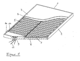
Im Folgenden wird anhand der Figuren 1 - 3 eine konkrete Ausgestaltung der Erfindung beschrieben. Figur. 1 zeigt einen Kollektor 1 im Schnitt. Er besteht aus dem ggf. seitlich isolierten Gehäuse 2, der transparenten Abdeckung 3, dem auf der Oberseite Strahlung absorbierenden Absorberblech 4, dem Sole-Strömüngskanal 5, hier als Mäander ausgeführt, die mit den beiden Sammlerrohren 6a und 6b verbunden ist, dem Profilblech 7, der Bodenisolierung 8 und dem Ventilator 9, der die Luft 11 ansaugen kann.In the following, a concrete embodiment of the invention will be described with reference to the figures 1-3. Figure. 1 shows a
Figur 2 zeigt einen Kollektor 1 von oben. Rechts und links von dem in Figur 2 dargestellten Kollektor können weitere Kollektoren angeschlossen werden, dabei werden jeweils beide Sammlerrohre 6a und 6b miteinander verbunden. Figur 3 zeigt drei Kollektormodule miteinander verschaltet. Durch das untere Sammlerröhr 6a strömt die zu erwärmende Sole in jeden Kollektor ein und jeweils ein Teil der Sole strömt durch die Doppelmäander eines jeden Kollektors zunächst nach oben und dann wieder nach unten, um dann den Kollektor über den Sammler 6b zu verlassen. Die Sole wird beim Durchströmen des Kollektors entweder von der Sonne erwärmt, die das obere Absorberblech 4 aufheizt, oder - falls die Sonne nicht scheint - durch Luft. Luft 11 wird mithilfe des an der Unterseite des Kollektors 1 angebrachten Ventilators 9 eingesaugt und über den auf der Oberseite angebrachten Luftauslass 10 wieder ausgeblasen. Sie strömt dabei im Kreuzgegenstrom zur Doppelmäander 5 (aufgrund der hohen Anzahl der Mäanderwindungen entspricht das quasi einem Gegenstrom-Wärmeaustausch).FIG. 2 shows a
Statt der beschriebenen Ausführung sind erfindungsgemäß eine Vielzahl anderer Ausführungen möglich: z. B. kann die Anordnung nach Ansprüchen 1, 2 oder 4 und folgenden auch mit anderen. Absorber-Bauformen realisiert werden, beispielsweise mit Kissen- oder Rollbondabsorbern. Statt des Profilbleches sind erfindungsgemäß auch andere Formen der Oberflächenvergrößerung oder auch - in bestimmten Fällen- keine Oberflächenvergrößerung möglich. Beispielsweise kann bei entsprechender Ausführung der Strömungskanäle, das untere Blech auch flach sein oder komplett entfallen.Instead of the described embodiment a variety of other designs are possible according to the invention: z. B., the arrangement according to
Ein erfindungsgemäßer Aufbau mit flachem Blech besteht aus einem Verbund aus Absorberblech 4, und Sole-Strömungskanälen 5, wobei mehrere Kanäle parallel angeordnet sind und Längsrichtung verlaufen und dem auf der Unterseite aufgebrachten zweiten (flachen) Blech 7. Durch diesen Verbund entstehen zwischen dem oberen und unteren Blech 4 und 7 Strömungskanäle für die Luft, die die Luft nach oben bzw. nach unten führen.An inventive construction with flat sheet consists of a composite of
Oberflächen vergrößernde Strukturen können bei entsprechenden Sole-Strömungskanälen direkt aus dem oberen Absorberblech oder den Strömungskanälen selbst geformt sein.Surface enlarging structures can be formed directly from the upper absorber plate or the flow channels themselves with corresponding brine flow channels.
Auch sind andere Arten der transparenten Abdeckung möglich, z. B. eine Zwei- bzw. Mehrfachabdeckung, ein mit Edelstahl gefüllter oder evakuierter Raum zwischen den beiden Abdeckungen oder zwischen Abdeckung und Absorberoberseite.Also, other types of transparent cover are possible, for. B. a two- or multiple cover, filled with stainless steel or evacuated space between the two covers or between the cover and absorber top.
Die Luftansaug- und ausblasöffnungen können statt, wie auf Fig. 1 und 2 dargestellt, anders positioniert sein, z. B: seitlich oder an der Stirnseite des Kollektors oder auf der Oberseite über die gesamte Breite.The air intake and exhaust ports may instead be positioned differently, as shown in FIGS. 1 and 2, e.g. B: on the side or on the front side of the collector or on the top over the entire width.
Zahlreiche Profilierungsformgebungen sind für das Profilblech 7 neben der in Figur 2 dargestellten Form möglich: z. B. Rechteck-, Rauten-, Dreiecks- oder Trapezprofil und runde Formen aller Art oder auch die Kombination aus beidem.Numerous Profilierungsformgebungen are possible for the profile sheet 7 in addition to the shape shown in Figure 2: z. B. Rectangle, diamond, triangular or trapezoidal profile and round shapes of all kinds or the combination of both.
Statt der Sole können auch andere Flüssigkeiten, ggf. auch Wasser verwendet werden.Instead of the brine other liquids, possibly also water can be used.
- 11
- Kollektorcollector
- 22
- Gehäusecasing
- 33
- transparente Abdeckungtransparent cover
- 44
- auf der Oberseite Strahlung absorbierendes Absorberblechon the top of radiation absorbing absorber sheet
- 55
- Sole-Strömungskanal, insbesondere DoppelmäanderBrine flow channel, in particular Doppelmäander
- 66
- Sammlerrohre 6a und 6bCollector pipes 6a and 6b
- 77
- unteres Blech für Luft-Wärmeaustausch, Profilblechlower plate for air heat exchange, profiled sheet
- 88th
- Bodenisolierungfloor insulation
- 99
- Ventilatorfan
- 1010
- Luftauslassair outlet
- 1111
- Luftair
Claims (11)
dadurch gekennzeichnet, dass der Kollektor zwei Öffnungen, für den Luftein- und austritt, im unteren Bereich aufweist und bei der Anwendung als Luft-Sole-Wärmetauscher die Luft U-förmig in dem Kollektor zuerst.nach oben und dann wieder nach unten gelenkt wird.Solar collector (1) for heating liquid, in which the liquid can be heated both by absorption of solar radiation, and alternatively or combined by the heat exchange with ambient air, consisting of a housing (2) and a through-flow of the liquid to be heated absorber. / Air heat exchanger, wherein the housing is provided on the side facing the sun with a transparent cover (3),
characterized in that the collector has two openings, for the air inlet and outlet, in the lower region and in the application as an air-brine heat exchanger, the air is U-shaped in the collector erst.on up and then directed down again.
dadurch gekennzeichnet, dass die zu erwärmende Flüssigkeit durch die Strömungskanäle (5) im Gegenstrom oder Kreuzgegenstrom zu dem Luftstrom (11) geführt wird.Solar collector according to claim 1,
characterized in that the liquid to be heated is passed through the flow channels (5) in countercurrent or cross-counterflow to the air stream (11).
dadurch gekennzeichnet, dass die Strömungskanäle (5) aus einer Doppelmäander bestehen und zwei Sammlerrohre 6a, 6b im unteren Bereich des Kollektors angeordnet sind, die durch die Doppelmäander so miteinander verbunden sind, dass die Flüssigkeit auf der einen Hälfte des Kollektors (1) nach oben verläuft und auf der anderen Hälfte nach unten und durch Verbindung der Sammlerrohre mit den Sammlerrohren weiterer Kollektormodule eine gleichmäßig verteilte Paralleldurchströmung aller Module erreicht wird.Solar collector according to claim 2,
characterized in that the flow channels (5) consist of a Doppelmäander and two collector tubes 6a, 6b are arranged in the lower region of the collector, which are connected by the Doppelmäander so that the liquid on one half of the collector (1) upwards runs and on the other half down and by connecting the header pipes with the header pipes of other collector modules a uniformly distributed parallel flow of all modules is achieved.
dadurch gekennzeichnet, dass in dem Kollektor (1) ein Ventilator (9) integriert ist, der die Luft (11) durch den Kollektor bläst.Solar collector according to one of claims 1 - 3,
characterized in that in the collector (1) a fan (9) is integrated, which blows the air (11) through the collector.
dadurch gekennzeichnet, dass der Ventilator (9) Außenluft (11) von der Rückseite des Kollektors ansaugt und damit Luft einsaugen kann, die entweder durch Wärmeverluste an oder in der Gebäudehülle vorgewärmt ist, oder durch von der Gebäudehülle absorbierte und als Wärme gespeicherte Solarstrahlung.Solar collector according to claim 4,
characterized in that the fan (9) draws in outside air (11) from the back of the collector and thus can suck in air which is preheated either by heat losses on or in the building envelope, or absorbed by the building shell and stored as heat solar radiation.
dadurch gekennzeichnet, dass Abluft durch den Kollektor geblasen wird.Solar collector according to one of claims 1 - 5,
characterized in that exhaust air is blown through the collector.
dadurch gekennzeichnet, dass die Luft (11), die durch den Kollektor geblasen wird, nur unterhalb des Strahlung absorbierenden Absorberbleches (4) strömt und der Bereich unterhalb des Absorberbleches weitgehend dicht gegenüber dem Bereich oberhalb des Absorberbleches ausgeführt ist.Solar collector according to one of claims 1 - 6,
characterized in that the air (11), which is blown through the collector, flows only below the radiation absorbing absorber sheet (4) and the area below the absorber sheet is made substantially tightly opposite the area above the absorber sheet.
dadurch gekennzeichnet, dass der kombinierte Absorber / Luftwärmetauscher des Kollektors aus einem der Strahlung zugewandten und Strahlung absorbierenden Absorberblech (4) besteht, auf dessen Unterseite sich die Flüssigkeits-Strömungskanäle (5) oder zumindest die Unterseite der Bewandung dieser Kanäle befinden, sowie einem zweiten Blech (7) unterhalb der Strömungskanäle, das sich in direktem Kontakt mit den Strömungskanälen (5) und in einem Abstand zum Absorberblech (4) befindet, so dass ein Spalt zwischen beiden Blechen entsteht, durch den Luft (11) strömen kann.Solar collector according to one of claims 1 - 6,
characterized in that the combined absorber / air heat exchanger of the collector facing in one of the radiation and radiation absorbing absorber sheet (4) consists, on the underside of the liquid flow channels (5) or at least the underside of the Bewandung of these channels are located, and a second sheet (7) below the flow channels, which is in direct contact with the flow channels (5) and at a distance from the absorber plate (4), so that a gap between the two sheets is formed, can flow through the air (11).
dadurch gekennzeichnet, dass das zweite Blech (7) auf der Unterseite in Längsrichtung eine runde oder gekantete Wellenprofilierung aufweist.Solar collector according to claim 8
characterized in that the second plate (7) has a round or folded wave profiling on the underside in the longitudinal direction.
dadurch gekennzeichnet, dass das zweite Blech (7) Luftkanäle erzeugt, die die Luft (11) auf der einen Seite nach oben führen und auf der anderen wieder nach unten, wobei das Blech (7) mit Abstand zur oberen Stirnseite des Kollektors endet, so dass die auf der einen Hälfte nach oben geführte Luft (11) zur anderen Seite überströmen kann und dort wieder nach unten strömt.Solar collector according to claim 8 or 9
characterized in that the second plate (7) generates air ducts which guide the air (11) on one side up and on the other back down, wherein the plate (7) ends at a distance from the upper end side of the collector, so in that the air (11) guided upwards on one half can flow over to the other side and flows down there again.
dadurch gekennzeichnet, dass das der Strahlung zugewandte Absorberblech (4) und das zweite Blech (7) auf der Unterseite der Strömungskanäle (5) im gleichen Arbeitsgang in einem Lötofen mit den. Strömungskanälen (5) verlötet werden:Solar collector according to one of claims 8 - 10,
characterized in that the radiation-facing absorber sheet (4) and the second plate (7) on the underside of the flow channels (5) in the same operation in a brazing furnace with the. Flow channels (5) are soldered:
Applications Claiming Priority (1)
| Application Number | Priority Date | Filing Date | Title |
|---|---|---|---|
| DE202006016294U DE202006016294U1 (en) | 2006-10-21 | 2006-10-21 | Solar collector with combined air heat extraction |
Publications (3)
| Publication Number | Publication Date |
|---|---|
| EP1914488A2 true EP1914488A2 (en) | 2008-04-23 |
| EP1914488A3 EP1914488A3 (en) | 2012-10-24 |
| EP1914488B1 EP1914488B1 (en) | 2016-04-06 |
Family
ID=38969837
Family Applications (1)
| Application Number | Title | Priority Date | Filing Date |
|---|---|---|---|
| EP07020264.3A Not-in-force EP1914488B1 (en) | 2006-10-21 | 2007-10-17 | Combined solar collector for removal of hot air and production of warm water |
Country Status (2)
| Country | Link |
|---|---|
| EP (1) | EP1914488B1 (en) |
| DE (1) | DE202006016294U1 (en) |
Cited By (4)
| Publication number | Priority date | Publication date | Assignee | Title |
|---|---|---|---|---|
| DE202013008185U1 (en) | 2013-09-17 | 2014-12-18 | Consolar Solare Energiesysteme Gmbh | Solar collector with device for keeping air dry |
| DE102014102152A1 (en) | 2014-02-20 | 2015-08-20 | Viessmann Werke Gmbh & Co Kg | solar collector |
| CN105526734A (en) * | 2016-01-23 | 2016-04-27 | 赵延斌 | Fan driven solar heat absorber board |
| DE102017006550A1 (en) | 2017-07-11 | 2019-01-17 | Thomas Noll | HVACC system for heating, ventilation, air conditioning and central refrigerant supply for a building |
Families Citing this family (7)
| Publication number | Priority date | Publication date | Assignee | Title |
|---|---|---|---|---|
| CN102252439A (en) * | 2010-05-21 | 2011-11-23 | 中国农业机械化科学研究院呼和浩特分院 | Solar heat collection and accumulation device for supplying heat alternatively |
| DE202011103319U1 (en) * | 2011-07-12 | 2011-11-23 | Pa-Id Automation & Vermarktung Gmbh | "Solar system" |
| DE102011081450B4 (en) * | 2011-08-24 | 2016-11-03 | Müller Axel | Absorber unit and collector for solar thermal heating of a fluid |
| ES2533506B1 (en) * | 2013-04-26 | 2016-02-19 | Eva GARCÍA PEULA | Solar aerothermal collector |
| DE102014007614A1 (en) | 2014-05-26 | 2015-11-26 | Wilhelm Lappe | Method for producing a heat exchanger and thermal solar collector with a heat exchanger produced in this way |
| CN106907868B (en) * | 2017-03-17 | 2019-05-28 | 深圳东康前海新能源有限公司 | A kind of solar attachment and heat dump |
| DE102022105412A1 (en) | 2022-01-26 | 2023-08-31 | WERTWIN GmbH | Solar thermal collector |
Citations (7)
| Publication number | Priority date | Publication date | Assignee | Title |
|---|---|---|---|---|
| US420787A (en) | 1890-02-04 | Toy dray | ||
| US4172442A (en) | 1978-05-15 | 1979-10-30 | Bio Gas Systems, Inc. | Solar energy collector system and method |
| US4207867A (en) | 1977-06-29 | 1980-06-17 | Lincoln Hanks | Solar energy collector and method |
| DE10108900A1 (en) | 2001-02-23 | 2002-09-12 | 3M Espe Ag | Determination of the patient-related caries risk |
| EP1413835A2 (en) | 2002-10-21 | 2004-04-28 | Consolar Energiespeicher- und Regelungssysteme GmbH | Drainback solar collector |
| DE202004008888U1 (en) | 2004-06-04 | 2004-09-23 | SH Kunststoff-, Lüftungs- & Umwelttechnik GmbH | Solar collector for heating air and water comprises a space between a cover and an absorber that is formed as an air-flow chamber having inlet connectors and outlet connectors in a housing side wall |
| EP1830140A2 (en) | 2006-03-04 | 2007-09-05 | SCHÜCO International KG | Hybrid collector |
Family Cites Families (6)
| Publication number | Priority date | Publication date | Assignee | Title |
|---|---|---|---|---|
| DE2733172A1 (en) * | 1977-07-22 | 1979-02-01 | Progress Consult Untersuchunge | Radiant heat collection arrangement with liq. absorber - has air flow channel with inlet and outlet controlled by valve |
| US4227515A (en) * | 1979-04-18 | 1980-10-14 | Jacob Robert I | Dual phase solar water heater |
| DE19529108A1 (en) * | 1995-08-08 | 1997-02-13 | Rudolf Gschwend | Solar collector with flat housing - has transparent cover and underlying absorber coating plus fan assisted circulation through in-flow heat exchanger |
| DE10004180A1 (en) * | 1999-04-26 | 2000-11-09 | Valentin Rosel | Heat exchange cell for transporting heat through liquid has liquid flow paths exposed on solar irradiation path for supplying heat to vaporizing side of heat pump |
| DE10104900B4 (en) * | 2001-02-03 | 2005-10-20 | Mip Mittelstands Projekt Gmbh | Solar collector for room air conditioning and equipped with such solar panels air conditioning |
| WO2006102891A2 (en) * | 2005-03-29 | 2006-10-05 | Christensen Hans Joergen | Solar collector panel |
-
2006
- 2006-10-21 DE DE202006016294U patent/DE202006016294U1/en not_active Expired - Lifetime
-
2007
- 2007-10-17 EP EP07020264.3A patent/EP1914488B1/en not_active Not-in-force
Patent Citations (7)
| Publication number | Priority date | Publication date | Assignee | Title |
|---|---|---|---|---|
| US420787A (en) | 1890-02-04 | Toy dray | ||
| US4207867A (en) | 1977-06-29 | 1980-06-17 | Lincoln Hanks | Solar energy collector and method |
| US4172442A (en) | 1978-05-15 | 1979-10-30 | Bio Gas Systems, Inc. | Solar energy collector system and method |
| DE10108900A1 (en) | 2001-02-23 | 2002-09-12 | 3M Espe Ag | Determination of the patient-related caries risk |
| EP1413835A2 (en) | 2002-10-21 | 2004-04-28 | Consolar Energiespeicher- und Regelungssysteme GmbH | Drainback solar collector |
| DE202004008888U1 (en) | 2004-06-04 | 2004-09-23 | SH Kunststoff-, Lüftungs- & Umwelttechnik GmbH | Solar collector for heating air and water comprises a space between a cover and an absorber that is formed as an air-flow chamber having inlet connectors and outlet connectors in a housing side wall |
| EP1830140A2 (en) | 2006-03-04 | 2007-09-05 | SCHÜCO International KG | Hybrid collector |
Cited By (5)
| Publication number | Priority date | Publication date | Assignee | Title |
|---|---|---|---|---|
| DE202013008185U1 (en) | 2013-09-17 | 2014-12-18 | Consolar Solare Energiesysteme Gmbh | Solar collector with device for keeping air dry |
| DE102014013583A1 (en) | 2013-09-17 | 2015-03-19 | Consolar Solare Energiesysteme Gmbh | Solar collector with device for keeping air dry |
| DE102014102152A1 (en) | 2014-02-20 | 2015-08-20 | Viessmann Werke Gmbh & Co Kg | solar collector |
| CN105526734A (en) * | 2016-01-23 | 2016-04-27 | 赵延斌 | Fan driven solar heat absorber board |
| DE102017006550A1 (en) | 2017-07-11 | 2019-01-17 | Thomas Noll | HVACC system for heating, ventilation, air conditioning and central refrigerant supply for a building |
Also Published As
| Publication number | Publication date |
|---|---|
| DE202006016294U1 (en) | 2008-02-28 |
| EP1914488B1 (en) | 2016-04-06 |
| EP1914488A3 (en) | 2012-10-24 |
Similar Documents
| Publication | Publication Date | Title |
|---|---|---|
| EP1914488B1 (en) | Combined solar collector for removal of hot air and production of warm water | |
| EP3497381B1 (en) | Photovoltaic thermal module with air heat exchanger | |
| DE102005036492A1 (en) | Interior space e.g. office space, cooling and heating process for use in building, involves causing circulation guidance of cooled water circulation and heat water circulation by cooling water pump and cold water pump | |
| DE102008026505A1 (en) | Solar module, particularly for roof covering of building roof, and for solar surface of solar system, has photovoltaic active layer for transformation of solar radiation into electrical energy | |
| WO2009095232A1 (en) | Low energy building, in particular greenhouse or stable | |
| WO2017178125A1 (en) | Solar energy roof tile having a length-variable connecting element | |
| EP2218970B1 (en) | Tempering system | |
| DE2364598C2 (en) | Tabular heating element for underfloor heating | |
| EP2063193A1 (en) | Method of air conditioning a building | |
| WO2009024135A2 (en) | Solar collector for heating, preferably, air | |
| EP2746694A1 (en) | Thermal assembly, method for producing a thermal assembly and method for mounting a thermal assembly | |
| DE19600579C1 (en) | Roofing element, to utilise solar heat for cooling or air conditioning | |
| DE102011121135A1 (en) | Energy element i.e. roof module, for solar system in sealed roof area of building, has air duct thermally cooperated with photovoltaic cells and heat carrier spacer, and attached to exhaust air spacer | |
| DE2628442A1 (en) | Solar water heater - uses collection panel insulated around the edges and with internal air circulation | |
| DE2531907A1 (en) | Solar energy collector with plastic water pipes - has single thin wall pipe coiled between inlet and outlet | |
| EP0027147A1 (en) | Heat collecting system | |
| DE102008050833A1 (en) | Air conditioning system for use on flat roof of building for cooling e.g. living room, has pipelines transporting solar heat from flat roof to heat exchanger or end-user, where roof is cooled and/or heated by temperature control of medium | |
| DE202005016100U1 (en) | Solar thermo center for agriculture, has sandwich collectors via which heat carrier liquid flows and installed onto swiveling framework and pressure-breaking container, where liquid is heated in heat accumulator using heat exchanger | |
| DE202007016964U1 (en) | Air absorber solar collector combination for heat pumps | |
| DE102015212924A1 (en) | Active window module for thermal regulation of a building and process | |
| DE4427947A1 (en) | Electronic and electrical racking system for heat removal from digital data processing system | |
| EP1674801B1 (en) | Air conditioning element | |
| DE202016003756U1 (en) | Photovoltaic module with heat exchanger for solar radiation and air-heat | |
| DE3206624A1 (en) | CENTRAL AIR LIQUID SOLAR ENERGY COLLECTOR | |
| EP0073260B1 (en) | Device for use of environmental energy |
Legal Events
| Date | Code | Title | Description |
|---|---|---|---|
| PUAI | Public reference made under article 153(3) epc to a published international application that has entered the european phase |
Free format text: ORIGINAL CODE: 0009012 |
|
| AK | Designated contracting states |
Kind code of ref document: A2 Designated state(s): AT BE BG CH CY CZ DE DK EE ES FI FR GB GR HU IE IS IT LI LT LU LV MC MT NL PL PT RO SE SI SK TR |
|
| AX | Request for extension of the european patent |
Extension state: AL BA HR MK RS |
|
| PUAL | Search report despatched |
Free format text: ORIGINAL CODE: 0009013 |
|
| AK | Designated contracting states |
Kind code of ref document: A3 Designated state(s): AT BE BG CH CY CZ DE DK EE ES FI FR GB GR HU IE IS IT LI LT LU LV MC MT NL PL PT RO SE SI SK TR |
|
| AX | Request for extension of the european patent |
Extension state: AL BA HR MK RS |
|
| RIC1 | Information provided on ipc code assigned before grant |
Ipc: F24J 2/04 20060101AFI20120919BHEP Ipc: F24J 2/26 20060101ALI20120919BHEP |
|
| 17P | Request for examination filed |
Effective date: 20130422 |
|
| AKX | Designation fees paid |
Designated state(s): AT BE BG CH CY CZ DE DK EE ES FI FR GB GR HU IE IS IT LI LT LU LV MC MT NL PL PT RO SE SI SK TR |
|
| 17Q | First examination report despatched |
Effective date: 20140722 |
|
| GRAP | Despatch of communication of intention to grant a patent |
Free format text: ORIGINAL CODE: EPIDOSNIGR1 |
|
| INTG | Intention to grant announced |
Effective date: 20150112 |
|
| GRAP | Despatch of communication of intention to grant a patent |
Free format text: ORIGINAL CODE: EPIDOSNIGR1 |
|
| INTG | Intention to grant announced |
Effective date: 20151012 |
|
| GRAS | Grant fee paid |
Free format text: ORIGINAL CODE: EPIDOSNIGR3 |
|
| GRAA | (expected) grant |
Free format text: ORIGINAL CODE: 0009210 |
|
| AK | Designated contracting states |
Kind code of ref document: B1 Designated state(s): AT BE BG CH CY CZ DE DK EE ES FI FR GB GR HU IE IS IT LI LT LU LV MC MT NL PL PT RO SE SI SK TR |
|
| REG | Reference to a national code |
Ref country code: GB Ref legal event code: FG4D Free format text: NOT ENGLISH |
|
| REG | Reference to a national code |
Ref country code: AT Ref legal event code: REF Ref document number: 788263 Country of ref document: AT Kind code of ref document: T Effective date: 20160415 Ref country code: CH Ref legal event code: EP |
|
| REG | Reference to a national code |
Ref country code: IE Ref legal event code: FG4D Free format text: LANGUAGE OF EP DOCUMENT: GERMAN |
|
| REG | Reference to a national code |
Ref country code: DE Ref legal event code: R096 Ref document number: 502007014680 Country of ref document: DE |
|
| REG | Reference to a national code |
Ref country code: DE Ref legal event code: R084 Ref document number: 502007014680 Country of ref document: DE |
|
| REG | Reference to a national code |
Ref country code: LT Ref legal event code: MG4D Ref country code: NL Ref legal event code: MP Effective date: 20160406 |
|
| REG | Reference to a national code |
Ref country code: DE Ref legal event code: R082 Ref document number: 502007014680 Country of ref document: DE |
|
| PG25 | Lapsed in a contracting state [announced via postgrant information from national office to epo] |
Ref country code: NL Free format text: LAPSE BECAUSE OF FAILURE TO SUBMIT A TRANSLATION OF THE DESCRIPTION OR TO PAY THE FEE WITHIN THE PRESCRIBED TIME-LIMIT Effective date: 20160406 |
|
| PG25 | Lapsed in a contracting state [announced via postgrant information from national office to epo] |
Ref country code: FI Free format text: LAPSE BECAUSE OF FAILURE TO SUBMIT A TRANSLATION OF THE DESCRIPTION OR TO PAY THE FEE WITHIN THE PRESCRIBED TIME-LIMIT Effective date: 20160406 Ref country code: PL Free format text: LAPSE BECAUSE OF FAILURE TO SUBMIT A TRANSLATION OF THE DESCRIPTION OR TO PAY THE FEE WITHIN THE PRESCRIBED TIME-LIMIT Effective date: 20160406 Ref country code: IS Free format text: LAPSE BECAUSE OF FAILURE TO SUBMIT A TRANSLATION OF THE DESCRIPTION OR TO PAY THE FEE WITHIN THE PRESCRIBED TIME-LIMIT Effective date: 20160806 Ref country code: LT Free format text: LAPSE BECAUSE OF FAILURE TO SUBMIT A TRANSLATION OF THE DESCRIPTION OR TO PAY THE FEE WITHIN THE PRESCRIBED TIME-LIMIT Effective date: 20160406 |
|
| PG25 | Lapsed in a contracting state [announced via postgrant information from national office to epo] |
Ref country code: ES Free format text: LAPSE BECAUSE OF FAILURE TO SUBMIT A TRANSLATION OF THE DESCRIPTION OR TO PAY THE FEE WITHIN THE PRESCRIBED TIME-LIMIT Effective date: 20160406 Ref country code: LV Free format text: LAPSE BECAUSE OF FAILURE TO SUBMIT A TRANSLATION OF THE DESCRIPTION OR TO PAY THE FEE WITHIN THE PRESCRIBED TIME-LIMIT Effective date: 20160406 Ref country code: GR Free format text: LAPSE BECAUSE OF FAILURE TO SUBMIT A TRANSLATION OF THE DESCRIPTION OR TO PAY THE FEE WITHIN THE PRESCRIBED TIME-LIMIT Effective date: 20160707 Ref country code: PT Free format text: LAPSE BECAUSE OF FAILURE TO SUBMIT A TRANSLATION OF THE DESCRIPTION OR TO PAY THE FEE WITHIN THE PRESCRIBED TIME-LIMIT Effective date: 20160808 Ref country code: SE Free format text: LAPSE BECAUSE OF FAILURE TO SUBMIT A TRANSLATION OF THE DESCRIPTION OR TO PAY THE FEE WITHIN THE PRESCRIBED TIME-LIMIT Effective date: 20160406 |
|
| PG25 | Lapsed in a contracting state [announced via postgrant information from national office to epo] |
Ref country code: IT Free format text: LAPSE BECAUSE OF FAILURE TO SUBMIT A TRANSLATION OF THE DESCRIPTION OR TO PAY THE FEE WITHIN THE PRESCRIBED TIME-LIMIT Effective date: 20160406 |
|
| REG | Reference to a national code |
Ref country code: DE Ref legal event code: R097 Ref document number: 502007014680 Country of ref document: DE |
|
| PG25 | Lapsed in a contracting state [announced via postgrant information from national office to epo] |
Ref country code: SK Free format text: LAPSE BECAUSE OF FAILURE TO SUBMIT A TRANSLATION OF THE DESCRIPTION OR TO PAY THE FEE WITHIN THE PRESCRIBED TIME-LIMIT Effective date: 20160406 Ref country code: CZ Free format text: LAPSE BECAUSE OF FAILURE TO SUBMIT A TRANSLATION OF THE DESCRIPTION OR TO PAY THE FEE WITHIN THE PRESCRIBED TIME-LIMIT Effective date: 20160406 Ref country code: RO Free format text: LAPSE BECAUSE OF FAILURE TO SUBMIT A TRANSLATION OF THE DESCRIPTION OR TO PAY THE FEE WITHIN THE PRESCRIBED TIME-LIMIT Effective date: 20160406 Ref country code: DK Free format text: LAPSE BECAUSE OF FAILURE TO SUBMIT A TRANSLATION OF THE DESCRIPTION OR TO PAY THE FEE WITHIN THE PRESCRIBED TIME-LIMIT Effective date: 20160406 Ref country code: EE Free format text: LAPSE BECAUSE OF FAILURE TO SUBMIT A TRANSLATION OF THE DESCRIPTION OR TO PAY THE FEE WITHIN THE PRESCRIBED TIME-LIMIT Effective date: 20160406 |
|
| PLBE | No opposition filed within time limit |
Free format text: ORIGINAL CODE: 0009261 |
|
| STAA | Information on the status of an ep patent application or granted ep patent |
Free format text: STATUS: NO OPPOSITION FILED WITHIN TIME LIMIT |
|
| PG25 | Lapsed in a contracting state [announced via postgrant information from national office to epo] |
Ref country code: BE Free format text: LAPSE BECAUSE OF NON-PAYMENT OF DUE FEES Effective date: 20161031 |
|
| 26N | No opposition filed |
Effective date: 20170110 |
|
| PG25 | Lapsed in a contracting state [announced via postgrant information from national office to epo] |
Ref country code: SI Free format text: LAPSE BECAUSE OF FAILURE TO SUBMIT A TRANSLATION OF THE DESCRIPTION OR TO PAY THE FEE WITHIN THE PRESCRIBED TIME-LIMIT Effective date: 20160406 |
|
| REG | Reference to a national code |
Ref country code: CH Ref legal event code: PL |
|
| GBPC | Gb: european patent ceased through non-payment of renewal fee |
Effective date: 20161017 |
|
| REG | Reference to a national code |
Ref country code: IE Ref legal event code: MM4A |
|
| REG | Reference to a national code |
Ref country code: FR Ref legal event code: ST Effective date: 20170630 |
|
| PG25 | Lapsed in a contracting state [announced via postgrant information from national office to epo] |
Ref country code: LI Free format text: LAPSE BECAUSE OF NON-PAYMENT OF DUE FEES Effective date: 20161031 Ref country code: FR Free format text: LAPSE BECAUSE OF NON-PAYMENT OF DUE FEES Effective date: 20161102 Ref country code: GB Free format text: LAPSE BECAUSE OF NON-PAYMENT OF DUE FEES Effective date: 20161017 Ref country code: CH Free format text: LAPSE BECAUSE OF NON-PAYMENT OF DUE FEES Effective date: 20161031 |
|
| PG25 | Lapsed in a contracting state [announced via postgrant information from national office to epo] |
Ref country code: LU Free format text: LAPSE BECAUSE OF NON-PAYMENT OF DUE FEES Effective date: 20161017 |
|
| REG | Reference to a national code |
Ref country code: DE Ref legal event code: R079 Ref document number: 502007014680 Country of ref document: DE Free format text: PREVIOUS MAIN CLASS: F24J0002040000 Ipc: F24S0010000000 |
|
| PG25 | Lapsed in a contracting state [announced via postgrant information from national office to epo] |
Ref country code: IE Free format text: LAPSE BECAUSE OF NON-PAYMENT OF DUE FEES Effective date: 20161017 |
|
| REG | Reference to a national code |
Ref country code: BE Ref legal event code: MM Effective date: 20161031 |
|
| REG | Reference to a national code |
Ref country code: AT Ref legal event code: MM01 Ref document number: 788263 Country of ref document: AT Kind code of ref document: T Effective date: 20161017 |
|
| PG25 | Lapsed in a contracting state [announced via postgrant information from national office to epo] |
Ref country code: AT Free format text: LAPSE BECAUSE OF NON-PAYMENT OF DUE FEES Effective date: 20161017 |
|
| PGFP | Annual fee paid to national office [announced via postgrant information from national office to epo] |
Ref country code: DE Payment date: 20171031 Year of fee payment: 11 |
|
| PG25 | Lapsed in a contracting state [announced via postgrant information from national office to epo] |
Ref country code: CY Free format text: LAPSE BECAUSE OF FAILURE TO SUBMIT A TRANSLATION OF THE DESCRIPTION OR TO PAY THE FEE WITHIN THE PRESCRIBED TIME-LIMIT Effective date: 20160406 Ref country code: HU Free format text: LAPSE BECAUSE OF FAILURE TO SUBMIT A TRANSLATION OF THE DESCRIPTION OR TO PAY THE FEE WITHIN THE PRESCRIBED TIME-LIMIT; INVALID AB INITIO Effective date: 20071017 |
|
| PG25 | Lapsed in a contracting state [announced via postgrant information from national office to epo] |
Ref country code: TR Free format text: LAPSE BECAUSE OF FAILURE TO SUBMIT A TRANSLATION OF THE DESCRIPTION OR TO PAY THE FEE WITHIN THE PRESCRIBED TIME-LIMIT Effective date: 20160406 Ref country code: MC Free format text: LAPSE BECAUSE OF FAILURE TO SUBMIT A TRANSLATION OF THE DESCRIPTION OR TO PAY THE FEE WITHIN THE PRESCRIBED TIME-LIMIT Effective date: 20160406 Ref country code: MT Free format text: LAPSE BECAUSE OF FAILURE TO SUBMIT A TRANSLATION OF THE DESCRIPTION OR TO PAY THE FEE WITHIN THE PRESCRIBED TIME-LIMIT Effective date: 20160406 |
|
| PG25 | Lapsed in a contracting state [announced via postgrant information from national office to epo] |
Ref country code: BG Free format text: LAPSE BECAUSE OF FAILURE TO SUBMIT A TRANSLATION OF THE DESCRIPTION OR TO PAY THE FEE WITHIN THE PRESCRIBED TIME-LIMIT Effective date: 20160406 |
|
| REG | Reference to a national code |
Ref country code: DE Ref legal event code: R119 Ref document number: 502007014680 Country of ref document: DE |
|
| PG25 | Lapsed in a contracting state [announced via postgrant information from national office to epo] |
Ref country code: DE Free format text: LAPSE BECAUSE OF NON-PAYMENT OF DUE FEES Effective date: 20190501 |