EP1914432A2 - Safety device for preventing damage to a device for torque transmission - Google Patents
Safety device for preventing damage to a device for torque transmission Download PDFInfo
- Publication number
- EP1914432A2 EP1914432A2 EP07118585A EP07118585A EP1914432A2 EP 1914432 A2 EP1914432 A2 EP 1914432A2 EP 07118585 A EP07118585 A EP 07118585A EP 07118585 A EP07118585 A EP 07118585A EP 1914432 A2 EP1914432 A2 EP 1914432A2
- Authority
- EP
- European Patent Office
- Prior art keywords
- safety device
- coupling
- recess
- drive
- bearing
- Prior art date
- Legal status (The legal status is an assumption and is not a legal conclusion. Google has not performed a legal analysis and makes no representation as to the accuracy of the status listed.)
- Granted
Links
- 230000005540 biological transmission Effects 0.000 title claims description 16
- 230000006378 damage Effects 0.000 title claims description 6
- 238000010168 coupling process Methods 0.000 claims abstract description 56
- 238000005859 coupling reaction Methods 0.000 claims abstract description 56
- 230000008878 coupling Effects 0.000 claims abstract description 55
- 230000033001 locomotion Effects 0.000 claims description 23
- 238000004378 air conditioning Methods 0.000 claims description 3
- 238000010438 heat treatment Methods 0.000 claims description 3
- 238000009423 ventilation Methods 0.000 claims description 3
- 230000006835 compression Effects 0.000 claims description 2
- 238000007906 compression Methods 0.000 claims description 2
- 230000007423 decrease Effects 0.000 claims 1
- 238000004519 manufacturing process Methods 0.000 claims 1
- 238000013459 approach Methods 0.000 description 5
- 230000001419 dependent effect Effects 0.000 description 5
- 208000027418 Wounds and injury Diseases 0.000 description 2
- 208000014674 injury Diseases 0.000 description 2
- 230000007246 mechanism Effects 0.000 description 2
- 230000009471 action Effects 0.000 description 1
- 230000008859 change Effects 0.000 description 1
- 238000006243 chemical reaction Methods 0.000 description 1
- 238000011161 development Methods 0.000 description 1
- 230000018109 developmental process Effects 0.000 description 1
- 238000005553 drilling Methods 0.000 description 1
- 210000003746 feather Anatomy 0.000 description 1
- 230000007257 malfunction Effects 0.000 description 1
- 230000007935 neutral effect Effects 0.000 description 1
- 230000002093 peripheral effect Effects 0.000 description 1
- 239000007787 solid Substances 0.000 description 1
- 239000006228 supernatant Substances 0.000 description 1
- 230000001360 synchronised effect Effects 0.000 description 1
Images

Classifications
-
- F—MECHANICAL ENGINEERING; LIGHTING; HEATING; WEAPONS; BLASTING
- F16—ENGINEERING ELEMENTS AND UNITS; GENERAL MEASURES FOR PRODUCING AND MAINTAINING EFFECTIVE FUNCTIONING OF MACHINES OR INSTALLATIONS; THERMAL INSULATION IN GENERAL
- F16D—COUPLINGS FOR TRANSMITTING ROTATION; CLUTCHES; BRAKES
- F16D7/00—Slip couplings, e.g. slipping on overload, for absorbing shock
- F16D7/04—Slip couplings, e.g. slipping on overload, for absorbing shock of the ratchet type
- F16D7/048—Slip couplings, e.g. slipping on overload, for absorbing shock of the ratchet type with parts moving radially between engagement and disengagement
Definitions
- the coupling element can also be realized by a ball which is engaged behind by a compression spring.
- the ball is in a guide channel radially or axially to the braking surface or the recess extending slidably mounted, so that here also the desired Coupling is ensured and at the same time the safety device acts in the desired manner.
- the securing device rotates with the hexagonal pin. According to the control is doing a left / right rotation by a certain angle. If it is determined via the transmission, which is not shown, that an overload occurs, the locking element 15 disengages from the recess 5 and slides on the braking surface 6 along until it stops or ends before, if the engine control have already reached the end angle should. In the reverse rotation is achieved automatically by the co-coupling that the first element is twisted. In this case, upon further rotation, the locking element 15 again comes into engagement with the recess 5. In order to avoid over-rotation of the drive, a stop 22 is further provided on the second element 10, which runs against a stop, not shown, in the housing.
Abstract
Description
Die Erfindung betrifft eine Sicherheitseinrichtung zur Vermeidung von Beschädigungen einer Vorrichtung zur Übertragung von Drehmomenten von einem manuellen oder motorischen Antrieb mittels einer Antriebswelle auf ein drehbar gelagertes Bauteil mit den im Oberbegriff des Anspruchs 1 angegebenen Merkmalen.The invention relates to a safety device for preventing damage to a device for transmitting torque from a manual or motor drive by means of a drive shaft to a rotatably mounted component having the features specified in the preamble of
Es ist bekannt, drehmomentabhängige Kupplungen zur Sicherung der Ab- oder Antriebsseite eines Gerätes gegen zu hohe Drehmomente oder Drehmomentenstöße einzusetzen. Diese drehmomentabhängigen Kupplungen sind für ein maximales Drehmoment auszulegen, bei dessen Überschreitung sich die Verbindung der Wellen löst. Solche Kupplungen und gattungsgemäße Sicherheitseinrichtungen sind für bestimmte Einsätze aus der
Analog zu den Rutschkupplungen lassen sich auch Dauermagnetkupplungen als verschleiß- und reibungsfreie Drehmomentenbegrenzer einsetzen. Drehmomentabhängige Kupplungen mit Formgehemmen weisen nach dem Lösen über einen begrenzten Drehwinkel im Allgemeinen ein deutlich niedrigeres Drehmoment auf. Nach Absenken des Drehmomentes und Wiedereinrasten sind auch diese Kupplungen wieder voll funktionsfähig. Die bekannten drehmomentabhängigen Kupplungen sind relativ kompliziert aufgebaut und für vollständige Drehbelastungen ausgelegt und können nicht beliebig klein ausgeführt werden.Analogous to the slip clutches, permanent magnet clutches can also be used as wear-resistant and friction-free torque limiters. Torque-dependent clutches with mold restraints generally have significantly lower torque after being released over a limited angle of rotation. After lowering the torque and re-engagement, these clutches are fully functional again. The known torque-dependent couplings are relatively complicated and designed for complete rotational loads and can not be made arbitrarily small.
Bei hand- oder motorangetriebenen Verschließsystemen für Durchgriffe und Schächte verschiedenster Art, beispielsweise auch für Luftdüsen zum Leiten eines Luftstromes aus einem Luftzuführschacht oder einer Leitung in Heizungs-, Lüftungs- oder Klimaanlagen, insbesondere in Kraftfahrzeugen, in den Innenraum können durch Unachtsamkeit zwischen die sich bewegenden Körper und/oder zwischen das feste Gehäuse und die Körper Gegenstände oder auch Finger gelangen, die eine Fortbewegung verhindern. Da die Teile in der Regel aus Kunststoff bestehen und nicht für hohe Belastungen ausgelegt sind, kann nicht ausgeschlossen werden, dass Teile des Übertragungsgetriebes oder die Zahnstangen als Folge eines solchen Eingriffs zerstört werden, so dass ein Austausch der ganzen Mechanik erforderlich ist, wenn es zu einer solchen Fehlbedienung kommt.In manual or motor-driven Verschließsystemen for passages and shafts of various kinds, for example, for air nozzles for directing an air flow from an air supply duct or a line in heating, ventilation or air conditioning systems, especially in motor vehicles, in the interior can by carelessness between the moving Body and / or get between the solid housing and the body objects or fingers that prevent locomotion. Since the parts are usually made of plastic and are not designed for high loads, can not be ruled out that parts of the transmission gear or the racks are destroyed as a result of such an intervention, so that an exchange of the entire mechanism is required when it such a malfunction comes.
Bei Luftdüsen, die ein Gehäuse aufweisen, das in einem Wanddurchbruch einsetzbar ist und das eine vorderseitige Luftausströmöffnung und einen rückseitigen Anschluss für einen Luftzuführschacht oder eine Luftzuführleitung aufweist, ist es üblich, in das Gehäuse vorderseitig mehrere Horizontal- und/oder dahinter liegend Vertikallamellen parallel und verschwenkbar anzuordnen, um eine gewünschte Strömungsrichtung der Luft zu erreichen. Solche Anordnungen, bei denen die Lamellen über Koppelelemente miteinander und mit einem Antrieb verbunden sind, sind beispielsweise aus der
Bei anderen Ausführungsformen gemäß
Auch Briefkästen lassen sich nach dem gleichen Prinzip mit schwenkbaren Klappen versehen, ebenso Abdeckklappen von Verstauräumen in PKW's oder LKW's. Diese können darüber hinaus auch mit Näherungssensoren betätigt werden. Bei Klappen, Lamellen und anderen Abdeckungselementen sowie Trommeldüsen sind in der Regel nur Schwenkbewegungen bis 180° erforderlich, um die gewünschten Funktions-änderungen, z. B. die Luftausströmrichtung, vorzunehmen.Even mailboxes can be provided on the same principle with hinged flaps, as well as flaps of storage spaces in cars or trucks. These can also be operated with proximity sensors. For flaps, fins and other cover elements and drum nozzles are usually only pivotal movements to 180 ° required to the desired functional changes, eg. B. the Luftausströmrichtung make.
Um eine Gefährdung der Getriebebauteile rotationsangetriebener Einrichtungen und auch eine Verletzungsgefahr zu vermeiden, liegt der Erfindung die Aufgabe zugrunde, eine Sicherheitseinrichtung anzugeben, die zwischen An-und Abtriebsseite, nämlich zwischen einer Antriebsvorrichtung und dem Stellgetriebe, zwischengefügt werden kann, um eine Zerstörung von Getriebeteilen oder eine Verletzung bei Berührung mit den bewegten Verschließ-oder Verstellteilen, die mit dem Antrieb gekoppelt sind, zu vermeiden, und gegenüber bekannten Sicherheitseinrichtungen mit radial wirkenden Kupplungen einfacher aufgebaut ist.To avoid endangering the transmission components of rotationally driven devices and also a risk of injury, the invention has for its object to provide a safety device that can be interposed between input and output side, namely between a drive device and the actuating gear to a destruction of transmission parts or an injury in contact with the moving closure or adjustment parts coupled to the drive, to avoid, and compared to known safety devices with radially acting clutches is simpler.
Die Aufgabe löst die Erfindung durch Ausgestaltung der Sicherheitseinrichtung gemäß der im Anspruch 1 angegebenen Lehre.The object is achieved by the invention by designing the safety device according to the teaching specified in
Vorteilhafte Weiterbildungen der Erfindung sind in den Unteransprüchen im Einzelnen angegeben.Advantageous developments of the invention are specified in the dependent claims in detail.
Die Sicherheitseinrichtung, die aus zwei relativ gegeneinander verdrehbaren, ineinandergefügten Elementen besteht und preiswert aus Kunststoff gefertigt werden kann, verhindert, dass beim Gelangen eines zu verstellenden Elementes gegen ein Hindernis der Motor oder Antrieb weiterdrehen kann, ohne dass eine Überlastung der Getriebeelemente erfolgt. Das Weiterfahren des Motors wird durch die Nachlaufzeit des Motors bis zum Erreichen des maximalen Auslenkwinkels der ineinandergefügten, relativ zueinander verdrehbaren Elemente bestimmt. Das eine Element ist dabei mit dem drehbar gelagerten Bauteil auf der Abtriebsseite verbunden, während das zweite Element mit der Antriebsseite und dort mit dem Antrieb gekoppelt ist. Zwischen den beiden Elementen ist mindestens ein radial oder axial wirkendes, mit Überschreiten eines bestimmten Drehmomentes ausrastbares Kupplungselement zwischengefügt. Wird ein bestimmtes Drehmoment überschritten, beispielsweise infolge des Zwischenschiebens eines Gegenstandes zwischen das schwenkbare oder drehbare Element und einer Gehäusewand, so gewährleistet die Sicherungseinrichtung, dass das Kupplungselement ausrastet und ein Weiterdrehen für den Restwinkelbereich erfolgt, welcher Restwinkelbereich durch die Motorsteuerung vorgesehen ist. Im Falle der Rückstellung, also der Richtungsänderung, rastet das Kupplungselement wieder in die Ausnehmung ein, wenn diese erreicht wird, so dass ein synchrones Mitdrehen wieder erfolgt.The safety device, which consists of two relatively mutually rotatable, nested elements and can be inexpensively made of plastic, prevents that when an element to be adjusted against an obstacle, the motor or drive can continue to rotate without overloading the transmission elements takes place. The driving of the motor is determined by the follow-up time of the motor until reaching the maximum deflection angle of the interlocked, rotatable relative to each other elements. The one element is connected to the rotatably mounted component on the output side, while the second element is coupled to the drive side and there to the drive. Between the two elements at least one radially or axially acting, with a certain torque disengageable coupling element is interposed. If a certain torque is exceeded, for example as a result of the intermediate sliding of an object between the pivotable or rotatable element and a housing wall, the securing device ensures that the coupling element disengages and further rotation takes place for the residual angle range, which residual angle range is provided by the motor control. In the case of the provision, ie the change in direction, the coupling element snaps back into the recess when it is reached, so that a synchronous co-rotation takes place again.
Ist darüber hinaus vorgesehen, dass das Kupplungselement auf einer Bremsbahn entlang gleitet, so wird bei der Rückführung bzw. beim Zurückdrehen des Motors über das Kupplungselement sofort eine Rückdrehung unter Beachtung der Andruckkräfte und Reibkraft zwischen der Bremsfläche und dem Kupplungselement bewirkt und darüber ein Verschwenken der zu steuernden Mittel.If, in addition, it is provided that the coupling element slides along a brake track, a return rotation under consideration of the pressing forces and frictional force between the braking surface and the coupling element is immediately effected during the return or when the motor is turned back via the coupling element and, moreover, a pivoting of the controlling means.
Als Kupplungselemente werden radial wirkende Kupplungen eingesetzt. Als Kupplungselemente können verschiedene Ausführungen zur Anwendung kommen. Bewährt hat sich, dass mindestens ein Kupplungselement ein federbelastetes Rastelement mit in Drehrichtung der Elemente gebogener oder halbkugelrunder Form oder Keilform und an dem einen Element vorgesehen ist, während eine formangepasste Ausnehmung in dem zweiten Element eingebracht ist. Die Passung und die Federkraft sind dabei so dimensioniert, dass bei Überschreiten eines definierten Drehmomentes die Rastelemente aus den Rastausnehmungen herausgleiten und unter der Federwirkung auf einer Bremsfläche an dem Element, an dem sich die Ausnehmung befindet, entlang gleiten. Die Bremsfläche ist mit einem Anschlag zur Begrenzung des Gleitweges versehen. Der Winkel, der überstrichen wird, entspricht zwischen Anschlag und Ausnehmung dem Winkel der maximalen Verstellung in der einen Drehrichtung. Dies kann auch in der anderen Drehrichtung vorgesehen sein.As coupling elements radially acting clutches are used. As coupling elements different designs can be used. It has proven useful that at least one coupling element is provided with a spring-loaded detent element with a curved or hemispherical shape or wedge shape in the direction of rotation of the elements and on the one element, while a shape-adapted recess is made in the second element. The fit and the spring force are dimensioned so that when a defined torque is exceeded, the latching elements slide out of the latching recesses and slide along the spring action on a braking surface on the element on which the recess is located. The braking surface is provided with a stop for limiting the sliding path. The angle, which is swept, corresponds between stop and recess the angle of maximum adjustment in one direction. This can also be provided in the other direction of rotation.
Als Getriebe können verschiedene Getriebeausführungen, bis hin zum Zahnstangengetriebe zum Einsatz kommen. Auch kann auf der Antriebsseite der Antrieb über ein Zahnstangengetriebe erfolgen. Zu diesem Zweck kann beispielsweise das zweite Element ein fest montiertes oder ausgeformtes Ritzel aufweisen, in das eine Zahnstange eingreift, die ihrerseits von einem anderen Ritzel verschoben wird. Die Bremsflächen werden entsprechend den Anordnungen der Kupplungselemente radial oder axial in die Wand des anderen Elementes eingearbeitet. Sie können dabei so vertieft oder einschnürend vorgesehen sein, dass zum Anschlagsende hin das Drehmoment stets geringer wird.As a gearbox, various gear types, up to the rack gear can be used. Also can be done on the drive side of the drive via a rack gear. For this purpose, for example, the second element having a fixed or molded pinion, in which engages a rack, which in turn is displaced by another pinion. The braking surfaces are in accordance with the arrangements of the coupling elements radially or axially in the Wall of the other element incorporated. They can be so deepened or constricted that the torque is always lower towards the stop end.
Die Vorrichtung kann sowohl in die eine Richtung als auch in die andere Drehrichtung vom Antrieb im entkuppelten oder gekuppelten Zustand der Elemente gedreht werden. Dies ist insbesondere dann der Fall, wenn die Sicherheitseinrichtung in Verbindung mit einer Luftdüse mit Horizontal- oder Vertikallamellen eingesetzt wird, die bekanntlich um eine neutrale Lage in beide Richtungen verschwenkt werden können, um in gewünschter Weise einen Luftstrom abzulenken oder diesen auf Personen zu richten. Je nach Ausführungsform der Vorrichtung können im gekuppelten Zustand die Winkelmaße der Schwenkbewegung in die eine oder in die andere Richtung gleich groß oder voneinander abweichend ausgelegt sein.The device can be rotated both in one direction and in the other direction of rotation by the drive in the decoupled or coupled state of the elements. This is particularly the case when the safety device is used in conjunction with an air nozzle with horizontal or vertical louvers, which can be pivoted to a neutral position in both directions, as is known, to deflect a desired air flow or direct it to people. Depending on the embodiment of the device, in the coupled state, the angular dimensions of the pivoting movement in one or the other direction can be designed to be the same size or differing from one another.
Die Antriebssteuerung bewirkt immer nur die maximale Schwenkbewegung in die eine oder in die andere Richtung. Innerhalb dieser Schwenkbewegung kann dann die Sicherheitseinrichtung einwirken, falls auf der Abgangsseite Hindernisse auftreten, gegen die die zu betätigenden Bauelemente laufen. Als besonders vorteilhaft hat es sich erwiesen, dass das erste und das zweite Element der Sicherheitseinrichtung einen Lagerabschnitt aufweisen, mit dem das Element drehbar in einem konturenangepassten Lager eines Gehäuses gelagert ist, das aus zwei Lagerschalen besteht, die miteinander verbindbar sind. Dadurch ist es möglich, die vormontierte Sicherheitseinrichtung in das Gehäuse zu integrieren, bevor der Antriebsmotor mit seiner Welle in die konturenangepasste Lageröffnung in dem zweiten Element eingeschoben wird. Um eine Mitnahme sicherzustellen, kann es sich hierbei um eine polygonale Bohrung handeln, in die ein Zapfen mit angepasstem polygonalen Querschnitt eingesteckt wird. Die Lagerungsbohrung kann in einem zylinderförmigen Verlängerungsstück eingebracht sein, das seinerseits in das erste Element in einer Lagerbohrung eingeführt und darin sicher gehalten wird. Dies kann beispielsweise durch Verrastungen sichergestellt werden. Wenn durch stirnseitige Begrenzungen ein Auseinanderfallen der Verbindung der beiden Elemente, die die Sicherheitseinrichtung bilden, nicht gegeben ist, können diese auch lose miteinander verbunden sein. Ferner kann am ersten Element ein Mitnahmekranz vorgesehen sein, der vorstehende Mitnahmeansätze und/oder Befestigungseinrichtungen zum Fixieren in konturenangepassten Ausnehmungen oder zum Verbinden mit korrespondierenden Befestigungseinrichtungen an einem drehbaren Bauteil, beispielsweise an dem eines Getriebes, aufweist. Solche Mitnahmeansätze können radial an einem Ring vorstehen, der aus der Ringwand des Bauteils ausgeformt ist.The drive control always causes only the maximum pivoting movement in one or the other direction. Within this pivoting movement, the safety device can then act if obstacles occur on the outlet side, against which the components to be actuated run. To be particularly advantageous, it has been found that the first and the second element of the safety device have a bearing portion with which the element is rotatably mounted in a contour-matched bearing of a housing consisting of two bearing shells, which are connectable to each other. This makes it possible to integrate the pre-assembled safety device in the housing before the drive motor is inserted with its shaft in the contour-matched bearing opening in the second element. To ensure a capture, this may be a polygonal hole into which a pin is inserted with an adapted polygonal cross-section. The bearing bore can be incorporated in a cylindrical extension piece, which in turn into the first element in introduced a bearing bore and held securely therein. This can be ensured for example by locking. If by frontal boundaries a falling apart of the connection of the two elements which form the safety device is not given, they may also be loosely connected to each other. Further, a driving ring may be provided on the first element, the above entrainment approaches and / or fastening means for fixing in contour-matched recesses or for connecting with corresponding fastening means on a rotatable component, for example on that of a transmission has. Such entrainment approaches may project radially on a ring which is formed from the annular wall of the component.
Mit dem drehbaren Bauteil kann auch ein Ritzel gekoppelt sein oder das drehbare Bauteil als solches ein Ritzel aufweisen, so dass hierüber eine Getriebeeinrichtung koppelbar ist, die die Rotationsbewegung in eine Linearbewegung oder eine andere Rotationsbewegung transformiert. In weiterer Ausgestaltung können an dem einen Element auf einem Umfangsring, ausgehend von einer Rastausnehmung, einseitig oder beidseitig Bremsflächen über einen bestimmten Winkel verlaufend angeordnet sein. In dem anderen Element ist eine ringförmige Ausnehmung eingearbeitet, in die der Ring mit der Bremsfläche einsetzbar ist. Das Kupplungs- oder Rastelement steht in die ringförmige Ausnehmung vor. In dem anderen Element ist eine ringförmige Ausnehmung eingearbeitet, in die der Ring mit der Bremsfläche einsetzbar ist. Das Kupplungs- oder Rastelement ist an der ringförmigen Ausnehmung vorstehend an der Innenseite vorgesehen und greift in die Rastausnehmung ein.A pinion can also be coupled to the rotatable component or the rotatable component as such can have a pinion, so that a transmission device can be coupled thereto, which transforms the rotational movement into a linear movement or another rotational movement. In a further embodiment, on one element on a peripheral ring, starting from a latching recess, braking surfaces may be arranged extending over a certain angle on one or both sides. In the other element, an annular recess is incorporated, in which the ring can be used with the braking surface. The coupling or locking element projects into the annular recess. In the other element, an annular recess is incorporated, in which the ring can be used with the braking surface. The coupling or locking element is provided on the annular recess protruding on the inside and engages in the recess.
Die beiden Teile bestehen aus Kunststoff und können so auf einfachste Weise miteinander verbunden werden, wobei gleichzeitig die gewünschte Rastverbindung oder Rastkupplungsverbindung entsteht, die einen Drehmomentenbegrenzer bildet. Das Kupplungs- oder Rastelement kann dabei an einer dünnwandigen Mantelfläche nach innen vorstehend angebracht sein und rastet unter Ausnutzung der federnden Elastizität des Wandabschnittes in die Ausnehmung ein. Zur Erzielung besonderer Federkräfte kann dieser Abschnitt stirnseitig freigeschnitten sein, so dass ein federnder Wandabschnitt gegeben ist, an dessen Innenseite in Art eines Vorsprungs der Rastansatz hervorsteht und in die Rastausnehmung eingreift. Damit nach dem Ausrasten im Falle der Überlastung das Drehmoment verringert wird, kann dieser Rastansatz dann auf einer Bremsbahn entlang gleiten, die so ausgeführt ist, dass das Drehmoment sich stetig verringert. Das freie Verdrehen erfolgt über den gesamten Winkelbereich, bis das Kupplungs- oder Rastelement an den Anschlag im Endbereich der Bremsfläche bzw. Bremsbahn gelangt, in der die Drehbewegung auch beendet ist. Beim Rückführen gleitet der Rastansatz auf der Bremsfläche entlang und überträgt die Drehbewegung in umgekehrter Richtung, so dass der eingeklemmte Gegenstand wieder freigegeben wird bzw. der Finger aus dem Öffnungsspalt einer Verschließklappe herausgezogen werden kann. Bei weiterer Drehung bis zum maximalen Winkelbereich gleitet das Rastelement wieder in die Rastausnehmung ein, so dass eine Mitnahme erfolgt. Das zweite Element kann einen Lagerabschnitt aufweisen, mit dem das zweite Element im ersten Element drehbar gelagert ist. Das zweite Element kann darüber hinaus einen radial oder axial vorstehenden Anschlag zur Begrenzung der Drehbewegung um den gewünschten Winkel aufweisen, der gegen einen ortsfesten Anschlag im Gehäuse bzw. an einer Trägerwand läuft.The two parts are made of plastic and can be connected to each other in the simplest way, at the same time the desired locking connection or detent coupling connection is formed, the torque limiter forms. The coupling or locking element can be mounted protruding inwards on a thin-walled lateral surface and snaps into the recess by utilizing the resilient elasticity of the wall section. To achieve special spring forces, this section can be cut open at the front, so that a resilient wall section is given, protruding on the inside in the manner of a projection of the locking projection and engages in the recess. So that after disengagement in the case of overloading the torque is reduced, this locking projection can then slide along a brake track, which is designed so that the torque is steadily reduced. The free rotation takes place over the entire angular range until the coupling or locking element reaches the stop in the end region of the braking surface or brake track, in which the rotational movement is completed. When returning the locking projection slides along the braking surface and transmits the rotational movement in the reverse direction, so that the clamped object is released again or the finger can be pulled out of the opening gap of a closing flap. Upon further rotation to the maximum angle range, the locking element slides back into the recess, so that a take-along takes place. The second element may have a bearing portion, with which the second element is rotatably mounted in the first element. The second element may also have a radially or axially projecting stop for limiting the rotational movement by the desired angle, which runs against a fixed stop in the housing or on a support wall.
Das Kupplungselement kann aber auch durch eine Kugel realisiert werden, die von einer Druckfeder hintergriffen wird. Die Kugel ist dabei in einem Führungskanal radial oder axial zur Bremsfläche oder der Ausnehmung verlaufend verschiebbar gelagert, so dass auch hierüber die gewünschte Kupplung sichergestellt ist und zugleich die Sicherheitseinrichtung in gewünschter Weise wirkt.But the coupling element can also be realized by a ball which is engaged behind by a compression spring. The ball is in a guide channel radially or axially to the braking surface or the recess extending slidably mounted, so that here also the desired Coupling is ensured and at the same time the safety device acts in the desired manner.
Es kann aber auch vorgesehen sein, dass bei axialer Anordnung des Kupplungselementes auf die Elemente in axialer Richtung eine Feder wirkt, die beim Ausrasten des Kuppelelementes gespannt wird, wenn ein bestimmtes Drehmoment überschritten ist. Es versteht sich in diesem Fall, dass die Verbindung zwischen den Teilen so auszulegen ist, dass die Überstandshöhe des Kupplungselementes beim Auseinanderrücken erreicht wird.However, it can also be provided that in axial arrangement of the coupling element acts on the elements in the axial direction, a spring which is tensioned during disengagement of the coupling element when a certain torque is exceeded. It is understood in this case that the connection between the parts is to be designed so that the supernatant height of the coupling element is achieved when pushed apart.
Besonders bewährt hat sich der Einsatz einer Sicherheitseinrichtung nach der Erfindung in Verbindung mit dem Antrieb von Luftdüsen, insbesondere auch dem elektromotorischen Antrieb von Luftdüsen zum Leiten eines Luftstroms aus einem Luftzuführschacht oder einer Leitung in Heizungs-, Lüftungs- oder Klimaanlagen, insbesondere in Kraftfahrzeugen. Solche Luftdüsen weisen ein Gehäuse mit einer vorderseitigen Luftausströmöffnung und mit einem rückseitigen Anschluss für einen Luftzuführschacht oder einer Luftzuführleitung auf. Zwischen Antrieb und Getriebe der in dem Gehäuse vorgesehenen verschwenkbaren lamellenförmigen Luftleitmittel oder einem verschwenkbaren trommelförmigen oder runden Einsatz mit lamellenförmigen Luftleitmitteln ist die Sicherheitseinrichtung eingefügt und damit integrierter Bestandteil des Antriebs bzw. Getriebes. Dabei wirkt die Sicherheitseinrichtung völlig unabhängig von dem Folgegetriebe oder den zusätzlichen Getriebeteilen zum Antrieb weiterer Verstellelemente, wie beispielsweise auch die Luftklappe im Luftzuführschacht oder Vertikallamellen.Has proven particularly useful the use of a safety device according to the invention in conjunction with the drive of air nozzles, in particular the electric motor drive of air nozzles for conducting an air flow from an air supply duct or a pipe in heating, ventilation or air conditioning systems, especially in motor vehicles. Such air nozzles have a housing with a front air outlet opening and with a rear connection for an air supply duct or an air supply duct. Between the drive and transmission provided in the housing pivotable lamellar Luftleitmittel or a pivotable drum-shaped or round insert with lamellar Luftleitmitteln the safety device is inserted and thus integrated part of the drive or transmission. In this case, the safety device acts completely independent of the follower or the additional transmission parts to drive other adjusting elements, such as the air damper in the air supply duct or vertical slats.
Die Antriebseinrichtung kann ein von Hand betätigtes Stellrad sein, das um einen bestimmten Winkel in die eine oder andere Richtung verdreht werden kann. Es kann sich aber auch um einen elektromotorischen Antrieb handeln. Es kann ferner ein Antrieb sein, der ein Zahnstangengetriebe aufweist und eine longitudinale Bewegung zunächst in eine Rotationsbewegung umsetzt, die dann von der Sicherheitseinrichtung übertragen wird. Dem Fachmann werden hier mannigfaltige Ausführungen eröffnet.The drive means may be a hand-operated adjusting wheel, which can be rotated by a certain angle in one or the other direction. But it can also be an electric motor drive. It may also be a drive, which is a rack and pinion and first converts a longitudinal movement into a rotational movement, which is then transmitted by the safety device. The person skilled in various designs are opened here.
Die Erfindung wird nachfolgend anhand des in den Zeichnungen dargestellten Ausführungsbeispieles ergänzend erläutert.The invention will be explained in the following with reference to the embodiment shown in the drawings.
In den Zeichnungen zeigen:
- FIG 1
bis 6 - ein Ausführungsbeispiel einer Sicherheitseinrichtung, die erfindungsgemäß ausgelegt ist und sich insbesondere durch eine kleine Bauform auszeichnet,
- FIG 1
- eine perspektivische Darstellung des ersten Elementes der Sicherheitseinrichtung,
- FIG 2
- eine perspektivische Darstellung des zweites Elementes, das mit dem ersten Element durch Einsetzen verbindbar ist,
- FIG 3
und 4 - die in
den Figuren 1 und 2 dargestellten Elemente in umgekehrter Richtung perspektivisch, - FIG 5
- die Darstellung der Bremsflächen bei der Ausführung der ersten Elemente gemäß Figuren 1 und 3,
- FIG 6
- die Draufsicht auf das zweite Element mit dem federnden Rastelement,
- FIG 7
und 8 - das in FIG 6
gezeigte Element 1 in zwei perspektivischen Darstellungen mit einem zusätzlich aufgebrachten Zahnrad und - FIG 9
- eine Explosionszeichnung in perspektivischer Darstellung einer weiteren Sicherheitseinrichtung nach der Erfindung.
- 1 to 6
- An embodiment of a safety device, which is designed according to the invention and is characterized in particular by a small design,
- FIG. 1
- a perspective view of the first element of the safety device,
- FIG. 2
- a perspective view of the second element, which is connectable to the first element by inserting,
- 3 and 4
- the elements shown in Figures 1 and 2 in the opposite direction in perspective,
- FIG. 5
- the representation of the braking surfaces in the execution of the first elements according to Figures 1 and 3,
- FIG. 6
- the top view of the second element with the resilient latching element,
- FIGS. 7 and 8
- The
element 1 shown in FIG 6 in two perspective views with an additionally applied gear and - FIG. 9
- an exploded view in perspective view of another safety device according to the invention.
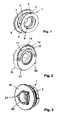
Das in den Figuren 1, 3 und 5 dargestellte erste Element 1 besteht aus einem Ringflansch 2, dem sich ein runder Lagerabschnitt 3 anschließt, mit dem das Element in ein konturenangepasstes Lager eines Gehäuses eingesetzt werden kann. Dem Lagerabschnitt 3 schließt sich ein Kupplungsring 4 an, der an der Oberseite eine Rastausnehmung und sich anschließende, aus Figur 5 deutlich sichtbare Bremsflächen 6 aufweist, die symmetrisch zur Mittenachse angeordnet sind und sich im Durchmesser verjüngen bis zu den Anschlägen 7, die die Bremsflächen in Drehrichtung begrenzen. Es ist ferner aus der Darstellung in Figur 1 ersichtlich, dass das Element 1 eine mittige Lagerungsbohrung 8 aufweist und eine zylinderförmige konzentrische Bohrung 9 größeren Durchmessers, in die der Lageransatz 11 des in den Figuren 2, 4 und 6 dargestellten zweiten Elementes 10 eingreift, wenn das zweite Element 10 mit dem verlängerten Lageransatz 12 mit Sechskantinnenführung 13 zur Aufnahme eines Sechskantzapfens eines Antriebmotors in die Lagerungsbohrung 8 eingesteckt wird. Die Besonderheit an dem zweiten Element 10 besteht nun darin, dass dieses einen Überwurfring 14 aufweist, der die Bremsfläche an dem Kupplungsring 4 und damit diesen übergreift. Im unteren Halbbogenabschnitt liegt die Innenfläche des Überwurfringes gleitend an der Unterseite des Kupplungsringes an. Im oberen Bereich ist durch die Formgebung der Bremsflächen ein Abstand hergestellt. Das Rastelement 15, das das Kupplungselement bildet und an der Innenseite des Überwurfringes vorsteht, rastet in die Ausnehmung 5 beim Zusammenschieben ein. Der obere Teil des Überwurfringes 14 ist freigeschnitten, und zwar durch Schrägverlauf der Oberkantenfläche 16, so dass dieser Teil elastisch ist und verformt werden kann. Dazu ist die Stirnfläche 17 im oberen Abschnitt des Elementes 10 unterbrochen. Der Freischnitt in seiner Länge ist identisch mit der Länge der Bremsflächen 6 am ersten Element 1. Der rahmenförmige Teil 18 des Überwurfringes 14 bildet also eine formangepasste Feder, so dass der Rastansatz 15 in die Ausnehmung 5 unter Federkraft einrastet.The
Zurückkommend auf das erste Element 1 sei darauf hingewiesen, dass an der Stirnfläche 19 des Ringflansches 2 ein ringförmiger Ansatz 20 mit Ansätzen 21 vorstehend vorgesehen ist, der an eine konturenangepasste Ausnehmung an dem hiermit kuppelbaren, drehbaren Bauteil des Folgegetriebes, z. B. dem Getriebe an einer Düse für Kraftfahrzeuge, ankuppelbar ist.Coming back to the
Es ist ersichtlich, dass im eingesetzten Zustand die Sicherungseinrichtung sich mit dem Sechskantzapfen dreht. Entsprechend der Steuerung erfolgt dabei eine Links/Rechtsdrehung um einen bestimmten Winkel. Wird über das Getriebe, das nicht dargestellt ist, festgestellt, dass eine Überlastung auftritt, rastet das Rastelement 15 aus der Ausnehmung 5 aus und gleitet auf der Bremsfläche 6 entlang bis zum Anschlag bzw. endet schon vorher, falls die Motorsteuerung schon den Endwinkel erreicht haben sollte. Bei der Rückdrehung wird automatisch durch die auftretende Mitkupplung erreicht, dass das erste Element verdreht wird. Dabei gelangt bei weiterem Drehen das Rastelement 15 wieder in Eingriff mit der Ausnehmung 5. Um ein Überdrehen des Antriebes zu vermeiden, ist ferner am zweiten Element 10 ein Anschlag 22 vorgesehen, der gegen einen nicht dargestellten Anschlag im Gehäuse läuft.It can be seen that in the inserted state, the securing device rotates with the hexagonal pin. According to the control is doing a left / right rotation by a certain angle. If it is determined via the transmission, which is not shown, that an overload occurs, the locking
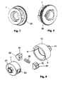
In den Figuren 7 und 8 ist ein erstes Element 1 der Sicherheitseinrichtung nach der Erfindung dargestellt, wie es aus den Figuren 1, 3 und 5 hervorgeht. Dieses Element 1 weist jedoch ergänzend ein Zahnrad 28 auf, so dass hierüber eine Krafteinleitung oder auch Kraftabgabe erfolgen kann. Dieses Zahnrad kann entweder mit einer Zahnstange zusammenwirken oder mit einem weiteren Zahnrad eines Getriebes. Das Beispiel verdeutlicht, dass die Elemente der Sicherheitseinrichtung noch zusätzliche Funktionen ausüben können.FIGS. 7 and 8 show a
In Figur 9 ist ein weiteres Beispiel einer Sicherheitseinrichtung dargestellt. Diese weist ein zylinderförmiges erstes Element 1 auf, an dem eine Befestigungseinrichtung 27 zum Einleiten des Drehmomentes auf ein Drehteil vorgesehen ist. In der Mantelwand befinden sich um 180° versetzt angeordnete Lagerausnehmungen 23, in denen die Rastelemente 15 radial verschiebbar gegen die Kraft einer zwischengefügten Feder 25 gelagert sind. Durch die Abstufung ist sichergestellt, dass die Rastelemente 15 durch den Durchbruch 23 nicht von der Feder herausgedrückt werden können. Die Rastelemente 15 weisen eine Keilform 26 an ihren Stirnseiten auf. Diese Keilform greift in die Ausnehmungen 5 an der Innenseite des Mantels des zweiten Elementes 10 ein. Zu diesem Zweck wird das Element 1 mit den eingesetzten Rastelementen 15 in die Innenbohrung des Elementes 10 eingesetzt. Das Element 10 weist an der Stirnseite zentrisch ein Ritzel 24 auf, über das beispielsweise ein Drehmoment auf das Sicherheitselement ausgeübt wird.FIG. 9 shows a further example of a safety device. This has a cylindrical
- 11
- Elementelement
- 22
- Ringflanschannular flange
- 33
- Lagerabschnittbearing section
- 44
- Kupplungsringcoupling ring
- 55
- Ausnehmungrecess
- 66
- Bremsflächebrake surface
- 77
- Anschlagattack
- 88th
- Lagerungsbohrungstorage bore
- 99
- Bohrungdrilling
- 1010
- zweites Elementsecond element
- 1111
- Lageransatzbearing projection
- 1212
- verlängerter Lageransatzextended bearing approach
- 1313
- Innenführunginner guide
- 1414
- ÜberwurfringCoupling ring
- 1515
- Rastelementlocking element
- 1616
- Oberkantenflächeupper edge surface
- 1717
- Stirnflächeface
- 1818
- rahmenförmiger Teilframe-shaped part
- 1919
- Stirnflächeface
- 2020
- ringförmiger Ansatzannular approach
- 2121
- Ansatzapproach
- 2222
- Anschlagattack
- 2323
- Lagerausnehmungbearing recess
- 2424
- Ritzelpinion
- 2525
- Federfeather
- 2626
- Keilformwedge shape
- 2727
- Befestigungseinrichtungfastening device
- 2828
- Zahnradgear
Claims (18)
Applications Claiming Priority (1)
| Application Number | Priority Date | Filing Date | Title |
|---|---|---|---|
| DE102006049367A DE102006049367B4 (en) | 2006-10-19 | 2006-10-19 | Safety device to prevent damage to a device for transmitting torque |
Publications (3)
| Publication Number | Publication Date |
|---|---|
| EP1914432A2 true EP1914432A2 (en) | 2008-04-23 |
| EP1914432A3 EP1914432A3 (en) | 2009-11-18 |
| EP1914432B1 EP1914432B1 (en) | 2012-03-07 |
Family
ID=38941908
Family Applications (1)
| Application Number | Title | Priority Date | Filing Date |
|---|---|---|---|
| EP07118585A Active EP1914432B1 (en) | 2006-10-19 | 2007-10-16 | Safety device for preventing damage to a device for torque transmission |
Country Status (3)
| Country | Link |
|---|---|
| EP (1) | EP1914432B1 (en) |
| AT (1) | ATE548578T1 (en) |
| DE (1) | DE102006049367B4 (en) |
Cited By (1)
| Publication number | Priority date | Publication date | Assignee | Title |
|---|---|---|---|---|
| CN113028715A (en) * | 2019-12-25 | 2021-06-25 | 浙江三花智能控制股份有限公司 | Air door device |
Families Citing this family (3)
| Publication number | Priority date | Publication date | Assignee | Title |
|---|---|---|---|---|
| DE102016103644B3 (en) * | 2016-03-01 | 2017-08-17 | Dr. Schneider Kunststoffwerke Gmbh | Ventilation device with a spring clutch |
| DE102019106818A1 (en) | 2019-03-18 | 2020-09-24 | Fischer Automotive Systems Gmbh & Co. Kg | Rotary control element for operating a ventilation nozzle in an automobile interior |
| DE102019122061B4 (en) | 2019-08-16 | 2023-10-19 | Illinois Tool Works Inc. | Braking device and device with such a braking device |
Citations (10)
| Publication number | Priority date | Publication date | Assignee | Title |
|---|---|---|---|---|
| DE7712518U1 (en) | 1977-04-21 | 1978-10-12 | Licentia Patent-Verwaltungs-Gmbh, 6000 Frankfurt | Coupling that can be disengaged depending on the torque |
| DE3012783A1 (en) | 1980-04-02 | 1981-11-19 | Jean Walterscheid Gmbh, 5204 Lohmar | SAFETY COUPLING |
| DE3716105C1 (en) | 1987-05-14 | 1988-12-22 | Walterscheid Gmbh Jean | Torque limiting clutch |
| DE4119748A1 (en) | 1991-06-15 | 1992-12-17 | Luchtenberg Gmbh & Co | FOLDABLE REAR MIRROR |
| DE4337750A1 (en) | 1993-11-05 | 1995-05-11 | Bosch Gmbh Robert | Motor vehicle exterior mirror |
| DE4344151A1 (en) | 1993-12-23 | 1995-06-29 | Grohe Armaturen Friedrich | Overload safeguard for connecting operating lever to valve spindle |
| DE19953484A1 (en) | 1999-11-06 | 2001-10-31 | Oechsler Ag | Disengageable swivel drive |
| DE202004004229U1 (en) | 2004-03-17 | 2004-06-03 | Dr. Schneider Engineering Gmbh | Air nozzle for guiding air flow from an air feed shaft or line into a heating, ventilation or air-conditioning system, especially in a motor vehicle, comprises air-guiding devices and radial air outlet openings deviating the air flow |
| DE202005012570U1 (en) | 2005-08-10 | 2005-10-20 | Dr. Schneider Engineering Gmbh | Air outlet in passenger cabin of vehicle, comprising fins performing air diffusing motion |
| US20060025224A1 (en) | 2003-07-28 | 2006-02-02 | Kazuyuki Saeki | Traveling device and power limiting mechanism |
Family Cites Families (4)
| Publication number | Priority date | Publication date | Assignee | Title |
|---|---|---|---|---|
| FR1242424A (en) * | 1959-10-23 | 1960-09-30 | Snap-in coupling, with torque limiter | |
| US3406583A (en) * | 1967-01-30 | 1968-10-22 | Gen Motors Corp | Drive mechanism having overload release means |
| DE2923447A1 (en) * | 1979-06-09 | 1980-12-11 | Fichtel & Sachs Ag | DRIVE FOR A LOCKING AND / OR LOCKING DEVICE ON A VEHICLE DOOR |
| US4702122A (en) * | 1986-09-02 | 1987-10-27 | The Scott & Fetzer Company | Bi-directional advance gear having a torque limiting clutch |
-
2006
- 2006-10-19 DE DE102006049367A patent/DE102006049367B4/en not_active Expired - Fee Related
-
2007
- 2007-10-16 EP EP07118585A patent/EP1914432B1/en active Active
- 2007-10-16 AT AT07118585T patent/ATE548578T1/en active
Patent Citations (10)
| Publication number | Priority date | Publication date | Assignee | Title |
|---|---|---|---|---|
| DE7712518U1 (en) | 1977-04-21 | 1978-10-12 | Licentia Patent-Verwaltungs-Gmbh, 6000 Frankfurt | Coupling that can be disengaged depending on the torque |
| DE3012783A1 (en) | 1980-04-02 | 1981-11-19 | Jean Walterscheid Gmbh, 5204 Lohmar | SAFETY COUPLING |
| DE3716105C1 (en) | 1987-05-14 | 1988-12-22 | Walterscheid Gmbh Jean | Torque limiting clutch |
| DE4119748A1 (en) | 1991-06-15 | 1992-12-17 | Luchtenberg Gmbh & Co | FOLDABLE REAR MIRROR |
| DE4337750A1 (en) | 1993-11-05 | 1995-05-11 | Bosch Gmbh Robert | Motor vehicle exterior mirror |
| DE4344151A1 (en) | 1993-12-23 | 1995-06-29 | Grohe Armaturen Friedrich | Overload safeguard for connecting operating lever to valve spindle |
| DE19953484A1 (en) | 1999-11-06 | 2001-10-31 | Oechsler Ag | Disengageable swivel drive |
| US20060025224A1 (en) | 2003-07-28 | 2006-02-02 | Kazuyuki Saeki | Traveling device and power limiting mechanism |
| DE202004004229U1 (en) | 2004-03-17 | 2004-06-03 | Dr. Schneider Engineering Gmbh | Air nozzle for guiding air flow from an air feed shaft or line into a heating, ventilation or air-conditioning system, especially in a motor vehicle, comprises air-guiding devices and radial air outlet openings deviating the air flow |
| DE202005012570U1 (en) | 2005-08-10 | 2005-10-20 | Dr. Schneider Engineering Gmbh | Air outlet in passenger cabin of vehicle, comprising fins performing air diffusing motion |
Cited By (1)
| Publication number | Priority date | Publication date | Assignee | Title |
|---|---|---|---|---|
| CN113028715A (en) * | 2019-12-25 | 2021-06-25 | 浙江三花智能控制股份有限公司 | Air door device |
Also Published As
| Publication number | Publication date |
|---|---|
| ATE548578T1 (en) | 2012-03-15 |
| DE102006049367B4 (en) | 2009-10-15 |
| EP1914432A3 (en) | 2009-11-18 |
| EP1914432B1 (en) | 2012-03-07 |
| DE102006049367A1 (en) | 2008-04-30 |
Similar Documents
| Publication | Publication Date | Title |
|---|---|---|
| AT504375B1 (en) | FURNITURE WITH A DRIVE DEVICE FOR MOVABLE FURNITURE PARTS | |
| EP1979134B1 (en) | Gearing, in particular for portable electric power tools | |
| EP2217783B1 (en) | Drive system for a closing part of a motor vehicle | |
| DE102011078691A1 (en) | Air guiding device for a motor vehicle | |
| WO2005073602A1 (en) | Gearbox comprising a displaceable shift fork and an actuator | |
| CH692270A5 (en) | Actuating device for a curtain. | |
| EP2094541A1 (en) | Electromechanical driving device for use in a tailgate of a motor vehicle | |
| DE102008013054A1 (en) | Actuation mechanism for engaging and disengaging a separating clutch with a turnable segment | |
| DE102016103644B3 (en) | Ventilation device with a spring clutch | |
| EP1914432B1 (en) | Safety device for preventing damage to a device for torque transmission | |
| DE19927033A1 (en) | Double-acting actuator for adjustment devices | |
| EP2558739B1 (en) | Coupling arrangement | |
| DE19734815C1 (en) | Drive device for adjustable road vehicle part, e.g. sun roof | |
| DE102018112633B4 (en) | Finger unit for a robot hand and a robot hand | |
| DE19940661C1 (en) | Tooth coupling for chain driven vehicles | |
| EP1303430A1 (en) | Wiper system | |
| DE102014201250A1 (en) | Device for switchably coupling a base with two coaxial shafts | |
| EP4130515B1 (en) | Driving device for an adjustable vehicle door | |
| WO2009027410A1 (en) | Driving device | |
| DE102016116876A1 (en) | drive arrangement | |
| DE102004044754B4 (en) | Tilt adjustment fitting for the backrest of a motor vehicle seat | |
| WO2020156619A1 (en) | Braking device | |
| EP1238858A2 (en) | Drive for a vehicle rear view mirror | |
| DE10357103A1 (en) | Medical instrument | |
| EP4047164B1 (en) | Drive for an apparatus, arrangement and domestic appliance |
Legal Events
| Date | Code | Title | Description |
|---|---|---|---|
| PUAI | Public reference made under article 153(3) epc to a published international application that has entered the european phase |
Free format text: ORIGINAL CODE: 0009012 |
|
| AK | Designated contracting states |
Kind code of ref document: A2 Designated state(s): AT BE BG CH CY CZ DE DK EE ES FI FR GB GR HU IE IS IT LI LT LU LV MC MT NL PL PT RO SE SI SK TR |
|
| AX | Request for extension of the european patent |
Extension state: AL BA HR MK RS |
|
| PUAL | Search report despatched |
Free format text: ORIGINAL CODE: 0009013 |
|
| AK | Designated contracting states |
Kind code of ref document: A3 Designated state(s): AT BE BG CH CY CZ DE DK EE ES FI FR GB GR HU IE IS IT LI LT LU LV MC MT NL PL PT RO SE SI SK TR |
|
| AX | Request for extension of the european patent |
Extension state: AL BA HR MK RS |
|
| 17P | Request for examination filed |
Effective date: 20100518 |
|
| AKX | Designation fees paid |
Designated state(s): AT BE BG CH CY CZ DE DK EE ES FI FR GB GR HU IE IS IT LI LT LU LV MC MT NL PL PT RO SE SI SK TR |
|
| GRAP | Despatch of communication of intention to grant a patent |
Free format text: ORIGINAL CODE: EPIDOSNIGR1 |
|
| GRAS | Grant fee paid |
Free format text: ORIGINAL CODE: EPIDOSNIGR3 |
|
| GRAA | (expected) grant |
Free format text: ORIGINAL CODE: 0009210 |
|
| AK | Designated contracting states |
Kind code of ref document: B1 Designated state(s): AT BE BG CH CY CZ DE DK EE ES FI FR GB GR HU IE IS IT LI LT LU LV MC MT NL PL PT RO SE SI SK TR |
|
| REG | Reference to a national code |
Ref country code: GB Ref legal event code: FG4D Free format text: NOT ENGLISH |
|
| REG | Reference to a national code |
Ref country code: AT Ref legal event code: REF Ref document number: 548578 Country of ref document: AT Kind code of ref document: T Effective date: 20120315 Ref country code: CH Ref legal event code: EP |
|
| REG | Reference to a national code |
Ref country code: IE Ref legal event code: FG4D Free format text: LANGUAGE OF EP DOCUMENT: GERMAN |
|
| REG | Reference to a national code |
Ref country code: DE Ref legal event code: R096 Ref document number: 502007009424 Country of ref document: DE Effective date: 20120503 |
|
| REG | Reference to a national code |
Ref country code: NL Ref legal event code: VDEP Effective date: 20120307 |
|
| PG25 | Lapsed in a contracting state [announced via postgrant information from national office to epo] |
Ref country code: NL Free format text: LAPSE BECAUSE OF FAILURE TO SUBMIT A TRANSLATION OF THE DESCRIPTION OR TO PAY THE FEE WITHIN THE PRESCRIBED TIME-LIMIT Effective date: 20120307 Ref country code: LT Free format text: LAPSE BECAUSE OF FAILURE TO SUBMIT A TRANSLATION OF THE DESCRIPTION OR TO PAY THE FEE WITHIN THE PRESCRIBED TIME-LIMIT Effective date: 20120307 |
|
| LTIE | Lt: invalidation of european patent or patent extension |
Effective date: 20120307 |
|
| PG25 | Lapsed in a contracting state [announced via postgrant information from national office to epo] |
Ref country code: FI Free format text: LAPSE BECAUSE OF FAILURE TO SUBMIT A TRANSLATION OF THE DESCRIPTION OR TO PAY THE FEE WITHIN THE PRESCRIBED TIME-LIMIT Effective date: 20120307 Ref country code: GR Free format text: LAPSE BECAUSE OF FAILURE TO SUBMIT A TRANSLATION OF THE DESCRIPTION OR TO PAY THE FEE WITHIN THE PRESCRIBED TIME-LIMIT Effective date: 20120608 Ref country code: LV Free format text: LAPSE BECAUSE OF FAILURE TO SUBMIT A TRANSLATION OF THE DESCRIPTION OR TO PAY THE FEE WITHIN THE PRESCRIBED TIME-LIMIT Effective date: 20120307 |
|
| PG25 | Lapsed in a contracting state [announced via postgrant information from national office to epo] |
Ref country code: CY Free format text: LAPSE BECAUSE OF FAILURE TO SUBMIT A TRANSLATION OF THE DESCRIPTION OR TO PAY THE FEE WITHIN THE PRESCRIBED TIME-LIMIT Effective date: 20120307 |
|
| PG25 | Lapsed in a contracting state [announced via postgrant information from national office to epo] |
Ref country code: IS Free format text: LAPSE BECAUSE OF FAILURE TO SUBMIT A TRANSLATION OF THE DESCRIPTION OR TO PAY THE FEE WITHIN THE PRESCRIBED TIME-LIMIT Effective date: 20120707 Ref country code: SE Free format text: LAPSE BECAUSE OF FAILURE TO SUBMIT A TRANSLATION OF THE DESCRIPTION OR TO PAY THE FEE WITHIN THE PRESCRIBED TIME-LIMIT Effective date: 20120307 Ref country code: EE Free format text: LAPSE BECAUSE OF FAILURE TO SUBMIT A TRANSLATION OF THE DESCRIPTION OR TO PAY THE FEE WITHIN THE PRESCRIBED TIME-LIMIT Effective date: 20120307 Ref country code: SI Free format text: LAPSE BECAUSE OF FAILURE TO SUBMIT A TRANSLATION OF THE DESCRIPTION OR TO PAY THE FEE WITHIN THE PRESCRIBED TIME-LIMIT Effective date: 20120307 Ref country code: RO Free format text: LAPSE BECAUSE OF FAILURE TO SUBMIT A TRANSLATION OF THE DESCRIPTION OR TO PAY THE FEE WITHIN THE PRESCRIBED TIME-LIMIT Effective date: 20120307 Ref country code: CZ Free format text: LAPSE BECAUSE OF FAILURE TO SUBMIT A TRANSLATION OF THE DESCRIPTION OR TO PAY THE FEE WITHIN THE PRESCRIBED TIME-LIMIT Effective date: 20120307 Ref country code: PL Free format text: LAPSE BECAUSE OF FAILURE TO SUBMIT A TRANSLATION OF THE DESCRIPTION OR TO PAY THE FEE WITHIN THE PRESCRIBED TIME-LIMIT Effective date: 20120307 |
|
| PG25 | Lapsed in a contracting state [announced via postgrant information from national office to epo] |
Ref country code: SK Free format text: LAPSE BECAUSE OF FAILURE TO SUBMIT A TRANSLATION OF THE DESCRIPTION OR TO PAY THE FEE WITHIN THE PRESCRIBED TIME-LIMIT Effective date: 20120307 Ref country code: PT Free format text: LAPSE BECAUSE OF FAILURE TO SUBMIT A TRANSLATION OF THE DESCRIPTION OR TO PAY THE FEE WITHIN THE PRESCRIBED TIME-LIMIT Effective date: 20120709 |
|
| PLBE | No opposition filed within time limit |
Free format text: ORIGINAL CODE: 0009261 |
|
| STAA | Information on the status of an ep patent application or granted ep patent |
Free format text: STATUS: NO OPPOSITION FILED WITHIN TIME LIMIT |
|
| PG25 | Lapsed in a contracting state [announced via postgrant information from national office to epo] |
Ref country code: DK Free format text: LAPSE BECAUSE OF FAILURE TO SUBMIT A TRANSLATION OF THE DESCRIPTION OR TO PAY THE FEE WITHIN THE PRESCRIBED TIME-LIMIT Effective date: 20120307 |
|
| 26N | No opposition filed |
Effective date: 20121210 |
|
| PG25 | Lapsed in a contracting state [announced via postgrant information from national office to epo] |
Ref country code: IT Free format text: LAPSE BECAUSE OF FAILURE TO SUBMIT A TRANSLATION OF THE DESCRIPTION OR TO PAY THE FEE WITHIN THE PRESCRIBED TIME-LIMIT Effective date: 20120307 |
|
| REG | Reference to a national code |
Ref country code: DE Ref legal event code: R097 Ref document number: 502007009424 Country of ref document: DE Effective date: 20121210 |
|
| BERE | Be: lapsed |
Owner name: DR. SCHNEIDER KUNSTSTOFFWERKE G.M.B.H. Effective date: 20121031 |
|
| PG25 | Lapsed in a contracting state [announced via postgrant information from national office to epo] |
Ref country code: ES Free format text: LAPSE BECAUSE OF FAILURE TO SUBMIT A TRANSLATION OF THE DESCRIPTION OR TO PAY THE FEE WITHIN THE PRESCRIBED TIME-LIMIT Effective date: 20120618 |
|
| PG25 | Lapsed in a contracting state [announced via postgrant information from national office to epo] |
Ref country code: MC Free format text: LAPSE BECAUSE OF NON-PAYMENT OF DUE FEES Effective date: 20121031 |
|
| REG | Reference to a national code |
Ref country code: CH Ref legal event code: PL |
|
| REG | Reference to a national code |
Ref country code: IE Ref legal event code: MM4A |
|
| REG | Reference to a national code |
Ref country code: DE Ref legal event code: R084 Ref document number: 502007009424 Country of ref document: DE |
|
| PG25 | Lapsed in a contracting state [announced via postgrant information from national office to epo] |
Ref country code: BG Free format text: LAPSE BECAUSE OF FAILURE TO SUBMIT A TRANSLATION OF THE DESCRIPTION OR TO PAY THE FEE WITHIN THE PRESCRIBED TIME-LIMIT Effective date: 20120607 Ref country code: BE Free format text: LAPSE BECAUSE OF NON-PAYMENT OF DUE FEES Effective date: 20121031 Ref country code: CH Free format text: LAPSE BECAUSE OF NON-PAYMENT OF DUE FEES Effective date: 20121031 Ref country code: LI Free format text: LAPSE BECAUSE OF NON-PAYMENT OF DUE FEES Effective date: 20121031 Ref country code: IE Free format text: LAPSE BECAUSE OF NON-PAYMENT OF DUE FEES Effective date: 20121016 |
|
| REG | Reference to a national code |
Ref country code: GB Ref legal event code: 746 Effective date: 20130806 |
|
| REG | Reference to a national code |
Ref country code: DE Ref legal event code: R084 Ref document number: 502007009424 Country of ref document: DE Effective date: 20130727 |
|
| PG25 | Lapsed in a contracting state [announced via postgrant information from national office to epo] |
Ref country code: MT Free format text: LAPSE BECAUSE OF FAILURE TO SUBMIT A TRANSLATION OF THE DESCRIPTION OR TO PAY THE FEE WITHIN THE PRESCRIBED TIME-LIMIT Effective date: 20120307 |
|
| REG | Reference to a national code |
Ref country code: AT Ref legal event code: MM01 Ref document number: 548578 Country of ref document: AT Kind code of ref document: T Effective date: 20121031 |
|
| PG25 | Lapsed in a contracting state [announced via postgrant information from national office to epo] |
Ref country code: AT Free format text: LAPSE BECAUSE OF NON-PAYMENT OF DUE FEES Effective date: 20121031 |
|
| PG25 | Lapsed in a contracting state [announced via postgrant information from national office to epo] |
Ref country code: TR Free format text: LAPSE BECAUSE OF FAILURE TO SUBMIT A TRANSLATION OF THE DESCRIPTION OR TO PAY THE FEE WITHIN THE PRESCRIBED TIME-LIMIT Effective date: 20120307 |
|
| PG25 | Lapsed in a contracting state [announced via postgrant information from national office to epo] |
Ref country code: LU Free format text: LAPSE BECAUSE OF NON-PAYMENT OF DUE FEES Effective date: 20121016 |
|
| PG25 | Lapsed in a contracting state [announced via postgrant information from national office to epo] |
Ref country code: HU Free format text: LAPSE BECAUSE OF FAILURE TO SUBMIT A TRANSLATION OF THE DESCRIPTION OR TO PAY THE FEE WITHIN THE PRESCRIBED TIME-LIMIT Effective date: 20071016 |
|
| REG | Reference to a national code |
Ref country code: FR Ref legal event code: PLFP Year of fee payment: 9 |
|
| REG | Reference to a national code |
Ref legal event code: R082 Ref country code: DE Ref legal event code: R082 Ref document number: 502007009424 Country of ref document: DE Representative=s name: DIE PATENTERIE GBR PATENT- UND RECHTSANWALTSSO, DE |
|
| REG | Reference to a national code |
Ref country code: FR Ref legal event code: PLFP Year of fee payment: 10 |
|
| REG | Reference to a national code |
Ref country code: DE Ref legal event code: R082 Ref document number: 502007009424 Country of ref document: DE |
|
| REG | Reference to a national code |
Ref country code: FR Ref legal event code: PLFP Year of fee payment: 11 |
|
| REG | Reference to a national code |
Ref country code: FR Ref legal event code: PLFP Year of fee payment: 12 |
|
| PGFP | Annual fee paid to national office [announced via postgrant information from national office to epo] |
Ref country code: FR Payment date: 20181026 Year of fee payment: 12 Ref country code: GB Payment date: 20181024 Year of fee payment: 12 |
|
| GBPC | Gb: european patent ceased through non-payment of renewal fee |
Effective date: 20191016 |
|
| PG25 | Lapsed in a contracting state [announced via postgrant information from national office to epo] |
Ref country code: GB Free format text: LAPSE BECAUSE OF NON-PAYMENT OF DUE FEES Effective date: 20191016 Ref country code: FR Free format text: LAPSE BECAUSE OF NON-PAYMENT OF DUE FEES Effective date: 20191031 |
|
| P01 | Opt-out of the competence of the unified patent court (upc) registered |
Effective date: 20230525 |
|
| PGFP | Annual fee paid to national office [announced via postgrant information from national office to epo] |
Ref country code: DE Payment date: 20231129 Year of fee payment: 17 |