EP1914201A1 - Dispositif destiné au traitement par U.V. de milieux liquides, en particulier de l'eau - Google Patents
Dispositif destiné au traitement par U.V. de milieux liquides, en particulier de l'eau Download PDFInfo
- Publication number
- EP1914201A1 EP1914201A1 EP07017626A EP07017626A EP1914201A1 EP 1914201 A1 EP1914201 A1 EP 1914201A1 EP 07017626 A EP07017626 A EP 07017626A EP 07017626 A EP07017626 A EP 07017626A EP 1914201 A1 EP1914201 A1 EP 1914201A1
- Authority
- EP
- European Patent Office
- Prior art keywords
- housing
- longitudinal axis
- housing longitudinal
- annular space
- port
- Prior art date
- Legal status (The legal status is an assumption and is not a legal conclusion. Google has not performed a legal analysis and makes no representation as to the accuracy of the status listed.)
- Withdrawn
Links
- XLYOFNOQVPJJNP-UHFFFAOYSA-N water Substances O XLYOFNOQVPJJNP-UHFFFAOYSA-N 0.000 title claims abstract description 22
- 239000007788 liquid Substances 0.000 title claims description 8
- 238000004659 sterilization and disinfection Methods 0.000 claims abstract description 17
- 230000001954 sterilising effect Effects 0.000 claims abstract description 14
- 230000035622 drinking Effects 0.000 claims abstract description 7
- 239000002351 wastewater Substances 0.000 claims abstract description 6
- 238000007599 discharging Methods 0.000 claims abstract 3
- 230000005855 radiation Effects 0.000 claims 1
- 239000003651 drinking water Substances 0.000 abstract description 7
- 239000008235 industrial water Substances 0.000 abstract 2
- 244000005700 microbiome Species 0.000 description 10
- 235000020188 drinking water Nutrition 0.000 description 5
- 230000015572 biosynthetic process Effects 0.000 description 4
- 238000005755 formation reaction Methods 0.000 description 4
- 230000001419 dependent effect Effects 0.000 description 3
- 239000010453 quartz Substances 0.000 description 3
- VYPSYNLAJGMNEJ-UHFFFAOYSA-N silicon dioxide Inorganic materials O=[Si]=O VYPSYNLAJGMNEJ-UHFFFAOYSA-N 0.000 description 3
- 230000002093 peripheral effect Effects 0.000 description 2
- 241000894006 Bacteria Species 0.000 description 1
- 230000006978 adaptation Effects 0.000 description 1
- 230000007423 decrease Effects 0.000 description 1
- 230000003247 decreasing effect Effects 0.000 description 1
- 230000000249 desinfective effect Effects 0.000 description 1
- 238000011161 development Methods 0.000 description 1
- 230000018109 developmental process Effects 0.000 description 1
- 238000009434 installation Methods 0.000 description 1
- 238000004519 manufacturing process Methods 0.000 description 1
- 238000000034 method Methods 0.000 description 1
- 238000012986 modification Methods 0.000 description 1
- 230000004048 modification Effects 0.000 description 1
- 238000005457 optimization Methods 0.000 description 1
- 230000035699 permeability Effects 0.000 description 1
Images

Classifications
-
- C—CHEMISTRY; METALLURGY
- C02—TREATMENT OF WATER, WASTE WATER, SEWAGE, OR SLUDGE
- C02F—TREATMENT OF WATER, WASTE WATER, SEWAGE, OR SLUDGE
- C02F1/00—Treatment of water, waste water, or sewage
- C02F1/30—Treatment of water, waste water, or sewage by irradiation
- C02F1/32—Treatment of water, waste water, or sewage by irradiation with ultraviolet light
- C02F1/325—Irradiation devices or lamp constructions
-
- C—CHEMISTRY; METALLURGY
- C02—TREATMENT OF WATER, WASTE WATER, SEWAGE, OR SLUDGE
- C02F—TREATMENT OF WATER, WASTE WATER, SEWAGE, OR SLUDGE
- C02F2201/00—Apparatus for treatment of water, waste water or sewage
- C02F2201/32—Details relating to UV-irradiation devices
- C02F2201/322—Lamp arrangement
- C02F2201/3223—Single elongated lamp located on the central axis of a turbular reactor
-
- C—CHEMISTRY; METALLURGY
- C02—TREATMENT OF WATER, WASTE WATER, SEWAGE, OR SLUDGE
- C02F—TREATMENT OF WATER, WASTE WATER, SEWAGE, OR SLUDGE
- C02F2201/00—Apparatus for treatment of water, waste water or sewage
- C02F2201/32—Details relating to UV-irradiation devices
- C02F2201/328—Having flow diverters (baffles)
-
- C—CHEMISTRY; METALLURGY
- C02—TREATMENT OF WATER, WASTE WATER, SEWAGE, OR SLUDGE
- C02F—TREATMENT OF WATER, WASTE WATER, SEWAGE, OR SLUDGE
- C02F2301/00—General aspects of water treatment
- C02F2301/02—Fluid flow conditions
- C02F2301/024—Turbulent
-
- C—CHEMISTRY; METALLURGY
- C02—TREATMENT OF WATER, WASTE WATER, SEWAGE, OR SLUDGE
- C02F—TREATMENT OF WATER, WASTE WATER, SEWAGE, OR SLUDGE
- C02F2301/00—General aspects of water treatment
- C02F2301/02—Fluid flow conditions
- C02F2301/026—Spiral, helicoidal, radial
Definitions
- the invention relates to a device according to the preamble of claim 1.
- UV disinfection systems or devices are used with increasing success, consisting essentially of a flowed through by the drinking or service water housing with at least one under-used in the housing UV lamps.
- the economics of such devices is i.a. according to how good the ratio of energy used for the operation of the UV lamp to killed microorganisms or bacteria. In order to optimize this ratio, it is necessary to suspend the microorganisms entrained in the water as evenly as possible from a UV light dose sufficient to kill the microorganisms and thus to ensure optimal sterilization.
- the UV light dose is the product of the UV light intensity and the exposure time.
- Each microorganism moves through the UV treatment space on an individual flow path and thus also undergoes treatment with an individual dose of UV light resulting from the length of the flow path, the flow rate, and the UV light intensity that exists along the flow path and others depends on the UV permeability of the water and the distance of the UV lamp.
- UV sterilization systems or devices have the disadvantage that for the treatment space between an inlet and an outlet flowing through water flow paths of very different lengths and thus depending on the respective flow path different UV light dosages and that the UV light dose strongly from the Flow rate depends on the flow through the UV treatment room by the water.
- the object of the invention is to provide a device which avoids these disadvantages.
- a device according to the patent claim 1 is formed.
- the introduction of the liquid medium to be treated takes place in the treatment space tangentially or approximately tangentially to a housing longitudinal axis enclosing a circle or circular cylindrical surface, so that to the UV Radiator results in a helical main or total flow, with partial vortex formation or turbulence. Since the twist of the helical total flow or the helical flow field u.a. depends on the flow rate at which the liquid medium enters the e.g. occurs annular treatment space, the number of turns on which each volume element of the liquid medium and thus entrained microorganisms move through the treatment room, depending on the flow rate.
- the intensity of partial vortices and turbulences is also dependent on the flow rate, i. the intensity of such vortex formation and turbulence increases with the flow velocity.
- a not insignificant role in this case also plays the orientation of the device in such a way that the housing longitudinal axis enclosed by the annular treatment space is oriented in the vertical direction or approximately in the vertical direction.
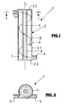
- the device 1 is a device in the form of a UV disinfection system for disinfecting drinking water with UV light.
- the device 1 consists essentially of an elongated circular cylindrical housing 2 with a peripheral wall 2.1, a housing top side 2.2 and a housing bottom 2.3.
- the housing 2 which is oriented in the application with its longitudinal axis L in the vertical direction or substantially in the vertical direction, has at its upper end an inlet 3 for the drinking or process water to be sterilized and at its lower end an outlet 4 for the Sterilized drinking or service water.
- the terminals 3 and 4 are each formed by pipe pieces or nozzles which open tangentially into the interior of the housing 2, i.
- the axes of the terminals 3 and 4 are each arranged in planes perpendicular to the housing longitudinal axis L and form tangents to an imaginary, the housing longitudinal axis L concentrically enclosing circular line, in the illustrated embodiment to circular lines, each having the same radius.
- a UV lamp 5 is provided inside the housing 2, which over the entire length of the housing 2.
- the UV lamp 5 consists in the illustrated embodiment of a quartz tube 6 and at least one quartz tube arranged in the UV tube.
- Light source sufficiently high power, such as a UV light emitting electrical discharge path.
- annular UV treatment chamber 7 is formed, which is traversed by the drinking water to be sterilized.
- the terminals 3 and 4 are further arranged so that the axis of these terminals is in a common, parallel to the housing longitudinal axis L extending plane, i. in the plan view of the device 1 ( Figure 2) appear to be arranged coaxially with each other.
- the arrangement of the housing longitudinal axis L in the vertical or approximately vertical direction and by the described embodiment of the device ensures that the drinking water to be sterilized with the entrained microorganisms flows through the treatment chamber 7 from top to bottom in a total flow helically enclosing the UV radiator 5, as indicated in the figures 1 and 2 with the respective arrow line 8.
- the UV treatment is carried out, wherein the necessary for killing the microorganisms UV dose is determined by the power of the UV lamp 5 and by the residence time in the treatment room 7.
- the residence time is in turn dependent on the flow rate in the treatment chamber 7 and on the length of the path that a considered water volume element or a microorganism carried along travels between the connection 3 and the connection 4 within the treatment space 7.
- the described arrangement of the terminals 3 and 4 in a common plane parallel to the housing longitudinal axis L further simplifies the installation of the device 1 in a piping system for drinking or service water.
- the length and the diameter of the housing 2 are adapted to the respective power required for the device.
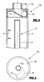
- FIGS. 2 and 3 show a device 1 a which differs from the device 1 essentially in that the housing 2a, which in turn has a circular cylindrical shape on its lateral surface 2a.
- the connection 4 instead of the connection 4, has a connection 4a, which is provided on the underside 2a. 3 of the housing 2a is provided and with its axis coaxially with the housing longitudinal axis L and also with the axis of the UV lamp 5 is located.
- the latter extends from the top 2a.2 of the housing 2a to near the bottom 2a.3, but is spaced therefrom, so that there is a flow for the water to the port 4a.
- the tangential arrangement of the terminal 3 also results in this embodiment, the UV radiator 5 enclosing helical or spiral total flow 8 with partial vortices and turbulence, especially in the lower part of the housing interior where the initially substantially helical total flow 8 in the running in the direction of the housing longitudinal axis L flow passes at the terminal 4a.
- Figures 5 and 6 show in partial view and side view and in plan view of a device 1 b, which differs from the devices 1 and 1a in that instead of the tangential terminal 3, a coaxially arranged with the housing longitudinal axis L connection 3b is provided.
- the upper housing part is formed in this embodiment of a housing upper part 10 having the connection 3b and in which a channel 11 is formed, on the one hand to the connection 3b in conjunction and on the other hand forms an opening 12 which tangentially into the UV emitter 5 enclosing treatment room 7 opens.
- connection forming the outlet is oriented either axially corresponding to the connection 4 tangentially to the housing longitudinal axis or correspondingly to the connection 4a in relation to the housing longitudinal axis ,
Applications Claiming Priority (1)
| Application Number | Priority Date | Filing Date | Title |
|---|---|---|---|
| DE200620015958 DE202006015958U1 (de) | 2006-10-18 | 2006-10-18 | Vorrichtung zur UV-Behandlung von flüssigen Medien, insbesondere von Wasser |
Publications (1)
| Publication Number | Publication Date |
|---|---|
| EP1914201A1 true EP1914201A1 (fr) | 2008-04-23 |
Family
ID=37950288
Family Applications (1)
| Application Number | Title | Priority Date | Filing Date |
|---|---|---|---|
| EP07017626A Withdrawn EP1914201A1 (fr) | 2006-10-18 | 2007-09-08 | Dispositif destiné au traitement par U.V. de milieux liquides, en particulier de l'eau |
Country Status (2)
| Country | Link |
|---|---|
| EP (1) | EP1914201A1 (fr) |
| DE (1) | DE202006015958U1 (fr) |
Families Citing this family (2)
| Publication number | Priority date | Publication date | Assignee | Title |
|---|---|---|---|---|
| DE102011110153A1 (de) * | 2011-08-12 | 2013-02-14 | Airbus Operations Gmbh | Wasserversorgungssystem mit Venturirohr |
| NL2021419B1 (nl) * | 2018-08-03 | 2020-02-12 | Bebro B V | Inrichting en werkwijze voor het filteren en/of zuiveren van vloeistof |
Citations (8)
| Publication number | Priority date | Publication date | Assignee | Title |
|---|---|---|---|---|
| JPS59150589A (ja) * | 1983-02-17 | 1984-08-28 | Raizaa Kogyo Kk | 用廃水の浄化方法とその装置 |
| WO1995015294A1 (fr) * | 1993-12-03 | 1995-06-08 | Louis Szabo | Sterilisateur uv a eau dote d'un generateur de turbulences |
| CA2249966A1 (fr) * | 1998-10-09 | 2000-04-09 | Leonid Pavlov | Methode et systeme pour la sterilisation par rayonnement ultraviolet de gaz et de fluides |
| US6409928B1 (en) * | 1997-01-31 | 2002-06-25 | Lynntech, Inc. | Photocatalytic oxidation of organics using a porous titanium dioxide membrane and an efficient oxidant |
| WO2003031338A2 (fr) * | 2001-10-09 | 2003-04-17 | Photoscience Japan Corporation | Appareil pour le traitement de l'eau |
| EP1382572A1 (fr) * | 2002-07-17 | 2004-01-21 | Vast Light Ltd. | Appareil de stérilisation à rayons UV |
| WO2005100256A1 (fr) * | 2004-04-13 | 2005-10-27 | Rafael Araiza | Dispositif pour traiter une substance liquide ou gazeuse au moyen de rayons uv |
| WO2006073409A1 (fr) * | 2004-01-27 | 2006-07-13 | Nolen, Gary | Desinfection modulaire d’un grand volume de liquide sous haute pression au moyen d’une helice fractionnaire |
-
2006
- 2006-10-18 DE DE200620015958 patent/DE202006015958U1/de not_active Expired - Lifetime
-
2007
- 2007-09-08 EP EP07017626A patent/EP1914201A1/fr not_active Withdrawn
Patent Citations (8)
| Publication number | Priority date | Publication date | Assignee | Title |
|---|---|---|---|---|
| JPS59150589A (ja) * | 1983-02-17 | 1984-08-28 | Raizaa Kogyo Kk | 用廃水の浄化方法とその装置 |
| WO1995015294A1 (fr) * | 1993-12-03 | 1995-06-08 | Louis Szabo | Sterilisateur uv a eau dote d'un generateur de turbulences |
| US6409928B1 (en) * | 1997-01-31 | 2002-06-25 | Lynntech, Inc. | Photocatalytic oxidation of organics using a porous titanium dioxide membrane and an efficient oxidant |
| CA2249966A1 (fr) * | 1998-10-09 | 2000-04-09 | Leonid Pavlov | Methode et systeme pour la sterilisation par rayonnement ultraviolet de gaz et de fluides |
| WO2003031338A2 (fr) * | 2001-10-09 | 2003-04-17 | Photoscience Japan Corporation | Appareil pour le traitement de l'eau |
| EP1382572A1 (fr) * | 2002-07-17 | 2004-01-21 | Vast Light Ltd. | Appareil de stérilisation à rayons UV |
| WO2006073409A1 (fr) * | 2004-01-27 | 2006-07-13 | Nolen, Gary | Desinfection modulaire d’un grand volume de liquide sous haute pression au moyen d’une helice fractionnaire |
| WO2005100256A1 (fr) * | 2004-04-13 | 2005-10-27 | Rafael Araiza | Dispositif pour traiter une substance liquide ou gazeuse au moyen de rayons uv |
Also Published As
| Publication number | Publication date |
|---|---|
| DE202006015958U1 (de) | 2007-04-05 |
Similar Documents
| Publication | Publication Date | Title |
|---|---|---|
| EP1737795B1 (fr) | Dispositif pour traiter une substance liquide ou gazeuse au moyen de rayons uv | |
| EP0011776B1 (fr) | Dispositif de stérilisation de fluides | |
| DE60027777T2 (de) | Sterilisierung von fluessigkeiten unter verwendung von ultraviolettem licht | |
| DE102010047782B3 (de) | Strömungsgleichrichter für geschlossene Rohrleitungen | |
| DE4317343C2 (de) | Vorrichtung zur Aufbereitung und Sterilisation von Wasser | |
| EP2949628A1 (fr) | Dispositif destine au rayonnement de liquides | |
| EP3227237A1 (fr) | Dispositif et son application pour le traitement uv de fluides | |
| EP1945337A1 (fr) | Chambre de turbulence | |
| DE19517381C1 (de) | Einrichtung zum Zerstören zellulärer Strukturen in Schlämmen biologischer Kläranlagen | |
| DE4138916A1 (de) | Verfahren und vorrichtung zur behandlung schadstoffbelasteter fluessigkeiten | |
| WO2001087473A1 (fr) | Procede et dispositif de traitement physicochimique de milieux fluides | |
| EP1914201A1 (fr) | Dispositif destiné au traitement par U.V. de milieux liquides, en particulier de l'eau | |
| DE4033792A1 (de) | Vorrichtung zur desinfektion von fluessigkeiten durch bestrahlung | |
| DE3537906A1 (de) | Zyklon-abscheider | |
| EP1025046B1 (fr) | Dispositif de degermage de l'eau traversant une installation sanitaire | |
| EP3134351A1 (fr) | Dispositif de traitement photochimique d'eau contaminée | |
| DE102011111367B4 (de) | Anlage zur Entkeimung oder Aufbereitung einer Flüssigkeit mittels UVC-Strahlung sowie dafür geeignetes Strahlermodul | |
| DE202008009583U1 (de) | Wasseraufbereitungsvorrichtung und System zur Aufbereitung von Wasser | |
| DE102019133198B4 (de) | Durchströmungsvorrichtung zum Verwirbeln von Trinkwasser | |
| DE102014015049B4 (de) | Vorichtung zur Behandlung eines Fluids mit UV-Strahlung | |
| DE102005046809B4 (de) | Vorrichtung zur Behandlung von Flüssigkeiten | |
| DE19838005C2 (de) | Einrichtung zum Entkeimen von Wasser, welches eine Sanitäreinrichtung durchströmt | |
| AT525380B1 (de) | Vorrichtung zur Flüssigkeitsdesinfektion | |
| DE19525920A1 (de) | Vorrichtung zum mechanischen Reinigen von Gasen und Flüssigkeiten | |
| DE3904346A1 (de) | Vorrichtung zum entkeimen von fluessigkeiten und gasen mittels ultravioletter strahlen im gegenstromprinzip |
Legal Events
| Date | Code | Title | Description |
|---|---|---|---|
| PUAI | Public reference made under article 153(3) epc to a published international application that has entered the european phase |
Free format text: ORIGINAL CODE: 0009012 |
|
| AK | Designated contracting states |
Kind code of ref document: A1 Designated state(s): AT BE BG CH CY CZ DE DK EE ES FI FR GB GR HU IE IS IT LI LT LU LV MC MT NL PL PT RO SE SI SK TR |
|
| AX | Request for extension of the european patent |
Extension state: AL BA HR MK RS |
|
| AKX | Designation fees paid | ||
| 17P | Request for examination filed |
Effective date: 20080924 |
|
| RBV | Designated contracting states (corrected) |
Designated state(s): AT BE BG CH CY CZ DE DK EE ES FI FR GB GR HU IE IS IT LI LT LU LV MC MT NL PL PT RO SE SI SK TR |
|
| D17P | Request for examination filed (deleted) | ||
| REG | Reference to a national code |
Ref country code: DE Ref legal event code: 8566 |
|
| STAA | Information on the status of an ep patent application or granted ep patent |
Free format text: STATUS: THE APPLICATION IS DEEMED TO BE WITHDRAWN |
|
| 18D | Application deemed to be withdrawn |
Effective date: 20081024 |