EP1914182A1 - Feeder transport system for hangers with objects hanging therefrom - Google Patents
Feeder transport system for hangers with objects hanging therefrom Download PDFInfo
- Publication number
- EP1914182A1 EP1914182A1 EP07016053A EP07016053A EP1914182A1 EP 1914182 A1 EP1914182 A1 EP 1914182A1 EP 07016053 A EP07016053 A EP 07016053A EP 07016053 A EP07016053 A EP 07016053A EP 1914182 A1 EP1914182 A1 EP 1914182A1
- Authority
- EP
- European Patent Office
- Prior art keywords
- transfer
- feed
- transport system
- bracket
- transport
- Prior art date
- Legal status (The legal status is an assumption and is not a legal conclusion. Google has not performed a legal analysis and makes no representation as to the accuracy of the status listed.)
- Granted
Links
- 239000000969 carrier Substances 0.000 claims 2
- 230000005484 gravity Effects 0.000 description 2
- 230000006835 compression Effects 0.000 description 1
- 238000007906 compression Methods 0.000 description 1
- 238000003780 insertion Methods 0.000 description 1
- 230000037431 insertion Effects 0.000 description 1
- 238000010409 ironing Methods 0.000 description 1
Images


Classifications
-
- B—PERFORMING OPERATIONS; TRANSPORTING
- B65—CONVEYING; PACKING; STORING; HANDLING THIN OR FILAMENTARY MATERIAL
- B65G—TRANSPORT OR STORAGE DEVICES, e.g. CONVEYORS FOR LOADING OR TIPPING, SHOP CONVEYOR SYSTEMS OR PNEUMATIC TUBE CONVEYORS
- B65G47/00—Article or material-handling devices associated with conveyors; Methods employing such devices
- B65G47/52—Devices for transferring articles or materials between conveyors i.e. discharging or feeding devices
- B65G47/60—Devices for transferring articles or materials between conveyors i.e. discharging or feeding devices to or from conveyors of the suspended, e.g. trolley, type
- B65G47/61—Devices for transferring articles or materials between conveyors i.e. discharging or feeding devices to or from conveyors of the suspended, e.g. trolley, type for articles
-
- B—PERFORMING OPERATIONS; TRANSPORTING
- B65—CONVEYING; PACKING; STORING; HANDLING THIN OR FILAMENTARY MATERIAL
- B65G—TRANSPORT OR STORAGE DEVICES, e.g. CONVEYORS FOR LOADING OR TIPPING, SHOP CONVEYOR SYSTEMS OR PNEUMATIC TUBE CONVEYORS
- B65G9/00—Apparatus for assisting manual handling having suspended load-carriers movable by hand or gravity
- B65G9/004—Loading or unloading arrangements
-
- B—PERFORMING OPERATIONS; TRANSPORTING
- B65—CONVEYING; PACKING; STORING; HANDLING THIN OR FILAMENTARY MATERIAL
- B65G—TRANSPORT OR STORAGE DEVICES, e.g. CONVEYORS FOR LOADING OR TIPPING, SHOP CONVEYOR SYSTEMS OR PNEUMATIC TUBE CONVEYORS
- B65G2201/00—Indexing codes relating to handling devices, e.g. conveyors, characterised by the type of product or load being conveyed or handled
- B65G2201/02—Articles
- B65G2201/0229—Clothes, clothes hangers
Abstract
Description
Die Erfindung betrifft ein Zuführ-Transport-System für Bügel mit darauf hängenden Gegenständen, insbesondere Kleidungsstücken.The invention relates to a feeding-transport system for hangers with objects hanging thereon, in particular items of clothing.
Aus der
Der Erfindung liegt daher die Aufgabe zugrunde, ein Zuführ-Transport-System der allgemeinen Gattung zu schaffen, mittels dessen jeweils ein Bügel in ein Roll-Halteelement eingehängt werden kann, mittels dessen dann ein Weitertransport des Bügels erfolgt.The invention is therefore an object of the invention to provide a feed-transport system of the general category, by means of which in each case a bracket can be hung in a roll-holding element, by means of which then a further transport of the bracket.
Diese Aufgabe wird erfindungsgemäß durch die Merkmale des Anspruchs 1 gelöst. Der Kern liegt der Erfindung liegt darin, dass das Übergabe-Rad jeweils ein Halteelement in einer Position aufnimmt, in der es gegenüber der Vertikalen schräg aus dem Übergabe-Rad herausragt, so dass die Aufnahme-Öffnung - in einer Projektion auf die Horizontale - nach oben offen ist. Durch den Übergabe-Spalt fällt dann jeweils taktweise nur ein Bügel nach unten, der von der Aufnahme-Öffnung aufgefangen wird, da das freie Ende des Hakens sich über der Aufnahme-Öffnung befindet. Der Haken fällt damit gleichsam in die Aufnahme-Öffnung hinein und wird hierdurch vom Halteelement gefangen. Danach wird das Halteelement durch taktweises Drehen in eine vertikale untere Lage gebracht, in der das jetzt mit einem Bügel beladene Halteelement aus dem Übergabe-Rad hinausgleiten kann, während das nachfolgende Halteelement gleichzeitig in die nächste freie Ausnehmung des Übergabe-Rades hineingleiten kann. Die Ansprüche 2 bis 4 geben hierfür vorteilhafte Ausgestaltungen an.This object is achieved by the features of claim 1. The core of the invention is that the transfer wheel each receives a holding element in a position in which it protrudes obliquely relative to the vertical from the transfer wheel, so that the receiving opening - in a projection to the horizontal - after is open at the top. By the transfer gap then falls in each case only one strap down, which is caught by the receiving opening, since the free end of the hook is located above the receiving opening. The hook thus falls as it were into the receiving opening and is thereby caught by the retaining element. Thereafter, the holding member is brought by clockwise rotation in a vertical lower position in which now loaded with a bracket holding element can slide out of the transfer wheel, while the subsequent holding element can slide into the next free recess of the transfer wheel simultaneously. The
Anspruch 5 gibt wieder, wie auf einfache Weise die Halteelemente dem Übergabe-Rad zugeführt werden können.
Anspruch 6 gibt wieder, wie die jeweils mit einem Bügel versehenen Halteelemente aus dem Übergabe-Rad weiter transportiert werden.
Durch die weiteren vorteilhaften Ausgestaltungen nach den Ansprüchen 7 bis 9 wird sichergestellt, dass jeder Bügel unmittelbar vor Erreichen des Übergabe-Spalts eine definierte Position einnimmt, in der sichergestellt ist, dass er vom Haltelement aufgefangen wird.The further advantageous embodiments according to claims 7 to 9 ensures that each bracket occupies a defined position immediately before reaching the transfer gap in which it is ensured that it is collected by the holding element.
Die Ansprüche 10 und 11, und zwar insbesondere Anspruch 11 geben wieder, wie bei einem mechanisierten Transport der Bügel zur Übergabe-Station bei Erreichen des Übergabe-Spaltes der Bügel nicht festgeklemmt wird.The
Die Ansprüche 12 und 13 geben wieder, wie Störungen bei der Übergabe des Bügels auf das Halteelement vermieden werden.The
Weitere Merkmale, Vorteile und Einzelheiten ergeben sich aus der nachfolgenden Beschreibung eines Ausführungsbeispiels anhand der Zeichnung. Es zeigt
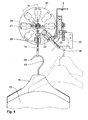
- Fig. 1
- eine Seiten-Längsansicht eines erfindungsgemäßen Zuführ-Transport-Systems,
- Fig. 2
- ein Roll-Halteelement,
- Fig. 3
- einen Querschnitt durch das Zuführ-Transport-System im Bereich seiner Übergabe-Station entsprechend der Schnittlinie III-III in Fig. 1,
- Fig. 4
- eine Stirnansicht der Übergabe-Station entsprechend der Schnittlinie IV-IV in Fig. 1,
- Fig. 5
- eine Teil-Ansicht einer Bügel-Führung im Bereich der Übergabe-Station und
- Fig. 6
- eine Draufsicht auf die Bügel-Führung.
- Fig. 1
- a side longitudinal view of a feed-transport system according to the invention,
- Fig. 2
- a roll-holding element,
- Fig. 3
- a cross section through the feed-transport system in the region of its transfer station along the section line III-III in Fig. 1,
- Fig. 4
- an end view of the transfer station according to the section line IV-IV in Fig. 1,
- Fig. 5
- a partial view of a strap guide in the area of the transfer station and
- Fig. 6
- a top view of the bracket guide.
Das in der Zeichnung dargestellte Zuführ-Transport-System 1 weist als Transport-Schiene eine Transport-Stange 2 auf, die im Wesentlichen kreisrund ausgebildet ist und einen nach oben offenen Längs-Schlitz 3 aufweist. Sie ist an einer als Hohlkasten ausgebildeten Trag-Einrichtung 4 gehalten, die mittels geeigneter Befestigungsmittel in einem Raum, beispielsweise an dessen Decke, anbringbar ist. Oberhalb der Transport-Stange 2 ist in der als Hohlkasten-Profil ausgebildeten Trag-Einrichtung 4 eine endlose Antriebs-Kette 5 angeordnet, deren unmittelbar oberhalb der Transport-Stange 2 angeordnetes Untertrum 6 in einer Förderrichtung 7 - in Fig. 1 von rechts nach links - antreibbar ist.The feed-transport system 1 shown in the drawing has as a transport rail on a
Bei der Antriebs-Kette 5 handelt es sich um eine sogenannte Rollen-Kette, an der nach unten ragende Mitnehmer 8 angebracht sind, die in den Längs-Schlitz 3 der Transport-Stange 2 eintauchen. Die Antriebs-Kette 5 ist in der Trag-Einrichtung 4 mittels Führungs-Schienen 9 gehalten und geführt.In the
Die Transport-Stange 2 dient zur Aufnahme der in üblicher Weise teilkreisförmigen Haken 10 von Bügeln 11, auf denen zu transportierende Gegenstände 12, in der Regel Kleidungsstücke, transportiert werden sollen. Der Transport der Bügel 11 mit den Gegenstände 12 erfolgt mittels der Antriebs-Kette 5 in Förderrichtung 7, wobei jeweils zwischen zwei benachbarten Mitnehmern 8 nur ein Bügel 11 aufgehängt sein soll. Der Transport der Bügel 11 erfolgt in Förderrichtung 7 zu einer - in Fig. 1 links angeordneten - Übergabe-Station 13, wo jeweils ein Bügel 11 in ein Roll-Halteelement 14 übergeben wird. Diese aus der
Im unteren Bereich des Roll-Halteelementes 14 ist in dessen Tragteil 15 eine Aufnahme-Öffnung 18 ausgebildet, in die jeweils ein Haken 10 eines Bügels 11 eingehängt werden soll. Am oberen Ende des Tragteils 15 ist ein Anschlag 19 ausgebildet, an dem ein nicht dargestellter Mitnehmer eines weiteren Transport-Systems angreifen kann, der ebenfalls in der
An der Übergabe-Station 13 ist ein taktweise drehantreibbares Übergabe-Rad 20 angeordnet, in dem nach außen offene Ausnehmungen 21 ausgebildet sind, die dem Querschnitt der Roll-Halteelemente 14 angepasst sind, also die Laufrollen 16, das Tragteil 15 und den Anschlag 19 aufnehmen können, wobei der untere Bereich des Tragteils 15 mit der Aufnahme-Öffnung 18 radial nach außen aus dem Übergabe-Rad 20 herausragt. Neben der Transport-Stange 2 - in Fig. 1 hinter dieser - ist eine Zuführ-Schiene 22 angeordnet, über die Roll-Haltelemente 14 dem Übergabe-Rad 20 zugeführt werden.At the transfer station 13 a cyclically rotationally
Auf dem Übergabe-Rad 20 sind die geschilderten Ausnehmungen 21 in gleichen Winkelabständen, im vorliegenden Fall von jeweils 45°, ausgebildet. Vor der Zuführ-Schiene 22 befindet sich jeweils eine Ausnehmung 21, die gegenüber der senkrecht nach unten weisenden Richtung um 45° schräg gestellt ist, - bezogen auf eine Uhr, je nach Blickrichtung - also bei 4.30 Uhr und 7.30 Uhr angeordnet ist. Die Zuführ-Schiene 22, die auf einer Seite direkt bis an das Übergabe-Rad 20 heranragt, ist also in gleicher Weise geneigt angeordnet, so dass jeweils ein Roll-Haltelement 14 von einer nicht dargestellten Einschubvorrichtung in eine Ausnehmung 21 in der geschilderten Schräglage eingeschoben wird.On the
An der Übergabe-Station 13 befindet sich zwischen der Transport-Stange 2 und einer Anschlag-Platte 23 ein Übergabe-Spalt 24, dessen Breite a in Förderrichtung 7 geringfügig größer ist als die Dicke b des Drahtes des Hakens 10. Es gilt b < a < 2 b. Wenn der Bügel 11 mit dem auf ihm hängenden Gegenstand 12 diesen Spalt 24 erreicht, dann fällt der Bügel 11 mit dem auf ihm hängenden Gegenstand 12 durch Schwerkraft senkrecht nach unten. Das Übergabe-Rad 20 ist derart angeordnet, dass das in ihm befindliche, soeben schräg eingeschobene Roll-Haltelement 14 mit seiner Aufnahme-Öffnung 18 sich unmittelbar unterhalb des freien Endes 25 des Bügel-Hakens 10 in einer Übergabe-Position befindet. Wenn also der Bügel-Haken 10 durch den Übergabe-Spalt 24 nach unten fällt, wird der Haken 10 in der Aufnahme-Öffnung 18 des Tragteils 15 des Roll-Haltelements 14 aufgenommen; der Bügel 11 mit dem auf ihm hängenden Gegenstand 12 ist also gleichsam auf das Roll-Halteelement 14 umgehängt worden. In dieser Übergabe-Position dient die Anschlag-Platte 23 auch als Anlage für das im Übergabe-Rad 20 befindliche, zu beladende Halteelement 14, so dass es eine definierte Position zu dem aufzunehmenden Bügel-Haken 10 hat. Es kann also nicht auf der der Zuführ-Schiene 22 entgegengesetzten Seite aus dem Übergabe-Rad 20 herausfallen. Jeweils nach einer solchen Aufnahme eines Bügels 11 wird das Übergabe-Rad 20 entsprechend der Winkelteilung bzw. des Winkelabstandes α der auf ihm ausgebildeten Ausnehmungen 21 um seine mittlere Drehachse 26 getaktet angetrieben, so dass die Ausnehmung 21 mit dem in ihm befindlichen, einen Bügel 11 tragenden Roll-Halteelement 14 aus der Übergabe-Position in die senkrecht nach unten gerichtete Ausschub-Position kommt. In dieser Ausschub-Position wird dieses Roll-Halteelement 14 zusammen mit dem auf ihm hängenden Bügel 11 aus dem Übergabe-Rad 20 von einem nicht dargestellten Ausstoß-Element ausgestoßen und gelangt in die Transport-Schiene 17, wo es dann weiter transportiert wird.At the
Damit der freie Fall des Bügels 11 im Übergabe-Spalt 24 nicht durch den in Förderrichtung 7 nacheilenden Mitnehmer 8 behindert wird, verlaufen die Mitnehmer 8 - wie Fig. 1 entnehmbar ist - nach unten zu ihrem freien Ende hin entgegen der Förderrichtung 7 nach hinten. Der nach unten fallende Haken 10 ist also frei von dem Mitnehmer 8, der ihn bis zum Übergabe-Spalt 24 geschoben hat.Thus, the free fall of the
An der Übergabe-Station 13 befindet sich weiterhin eine Bügel-Führung 27, die dem Profil des Hakens 10 angepasst ist, so dass der Bügel 11 mit dem auf ihm hängenden Gegenstand 12 in eine normal hängende Lage gezwungen wird, wie es beispielsweise in Fig. 5 und 6 angedeutet ist. Diese Bügel-Führung 27 weist zum einen eine Bügel-Anlagefläche 28 auf, gegen die der Bügel 11 mit seiner Außenseite anliegt. Des Weiteren ist eine federnd ausgebildete Andrück-Schiene 29 in der Transport-Stange 2 ausgebildet, auf die der Haken 10 aufläuft und durch die er gegen die Bügel-Anlagefläche 28 gedrückt wird. Diese Andrück-Schiene 29 ist mit einer schräg zur Förderrichtung 7 verlaufenden Auflauf-Kante 30 versehen und wird mittels einer in der Transport-Stange 2 angeordneten Druckfeder 31 nachgiebig nach außen in Richtung zur Bügel-Anlagefläche 28 gedrückt.At the
Claims (13)
dass benachbarte Ausnehmungen (21) am Übergabe-Rad (20) im Winkelabstand (α) von 45° ausgebildet sind.Feed-transport system (1) according to claim 1, characterized in that
that adjacent recesses (21) on the transfer wheel (20) at an angular distance (α) of 45 ° are formed.
dass das Übergabe-Rad (20) und der Übergabe-Spalt (24) derart zueinander angeordnet sind, dass ein um einen Winkelabstand (α) gegenüber der Vertikalen schräg nach unten aus dem Übergabe-Rad (20) ragendes Halteelement (14) sich mit seiner Aufnahme-Öffnung (18) unterhalb des freien Endes (25) eines in den Übergabe-Spalt (24) gelangenden Hakens (10) eines Bügels (11) befindet.Feed-transport system (1) according to claim 2, characterized in that
in that the transfer wheel (20) and the transfer gap (24) are arranged relative to one another in such a way that a holding element (14) protruding obliquely downwards from the transfer wheel (20) with respect to the vertical extends with its receiving opening (18) below the free end (25) of a passing into the transfer gap (24) reaching hook (10) of a bracket (11).
dass das Halteelement (14) sich mit seiner Aufnahme-Öffnung (18) unmittelbar unterhalb des freien Endes (25) eines in den Übergabe-Spalt (24) gelangenden Hakens (10) eines Bügels (11) befindet.Feed-transport system (1) according to one of claims 1 to 3, characterized
in that the holding element (14) is located with its receiving opening (18) directly below the free end (25) of a hook (10) of a bracket (11) reaching into the transfer gap (24).
dass dem Übergabe-Rad (20) eine Zuführ-Schiene (22) zur Zuführung von Haltelementen (14) vorgeordnet ist, die am Übergabe-Rad (20) um mindestens einen Winkelabstand gegenüber der Vertikalen in die Übergabe-Position zwischen Bügel (11) und Haltelement (14) verdreht ist.Feed-transport system (1) according to one of claims 1 to 4, characterized
in that the transfer wheel (20) is preceded by a supply rail (22) for the supply of holding elements (14) which, at the transfer wheel (20), is at least angularly offset from the vertical to the transfer position between the stirrups (11). and holding element (14) is twisted.
dass dem Übergabe-Rad (20) eine Transport-Schiene (17) nachgeordnet ist, die gegenüber der Übergabe-Position um mindestens einen Winkelabstand versetzt ist.Feed-transport system (1) according to one of claims 1 to 5, characterized
that the transfer wheel (20) is arranged downstream of a transport rail (17) which is offset from the transfer position by at least one angular distance.
dass an der Übergabe-Station (13) eine Bügel-Führung (27) vorgesehen ist.Feed-transport system (1) according to one of claims 1 to 6, characterized
that is provided at the transfer station (13) has a strap guide (27).
dass die Bügel-Führung (27) eine Bügel-Anlagefläche (28) zur führenden Anlage zumindestens eines Teil-Außenumfangs des Hakens (10) eines Bügels (11) aufweist.Feed-transport system (1) according to claim 7, characterized in that
in that the bow guide (27) has a bow contact surface (28) for leading at least part of the outer circumference of the hook (10) of a bow (11).
dass die Bügel-Führung (27) eine an der Innenseite des Hakens (10) eines Bügels (11) angreifende, federnd gelagerte Andrück-Schiene (29) aufweist.Feed-transport system (1) according to claim 7 or 8, characterized
that the strap guide (27) comprises an on the inside of the hook (10) of a bracket (11) engaging, spring-loaded press-on rail (29).
dass der Transport-Schiene (2) eine Antriebs-Kette (5) mit der Transport-Schiene (2) zugewandten Mitnehmern (8) zum Transport der Bügel (11) auf der Transport-Schiene (2) zugeordnet ist.Feed-transport system (1) according to one of claims 1 to 9, characterized
in that the transport rail (2) is associated with a drive chain (5) with carriers (8) facing the transport rail (2) for transporting the brackets (11) on the transport rail (2).
dass die Transport-Schiene (2) einen zur Antriebs-Kette (5) hin offenen Längs-Schlitz (3) aufweist, in den die Mitnehmer (8) eingreifen und
dass die Mitnehmer (8) nach unten und - bezogen auf eine zur Übergabe-Station (13) hin in gerichtete Förderrichtung (7) der Antriebs-Kette (5) - schräg nach hinten verlaufend ausgebildet sind.Feed-transport system (1) according to claim 10, characterized in that
that comprises the transport rail (2) to a drive chain (5) open towards the longitudinal slot (3) into which engage the carriers (8) and
in that the drivers (8) are designed to run downwards and, with respect to a delivery direction (13) towards the conveying direction (7) of the drive chain (5), extend obliquely to the rear.
dass der Übergabe-Spalt (24) eine Breite (a) aufweist, die größer als die Dicke (b) des Hakens (10) eines Bügels (11) und kleiner als die Gesamt-Dicke von zwei Haken (10) von Bügeln (11) ist.Feed-transport system (1) according to one of claims 1 to 11, characterized
that the transfer gap (24) has a width (a) which is greater than the thickness (b) of the hook (10) of a bracket (11) and smaller than the total thickness of two hooks (10) of stirrups (11 ).
dass in der Übergabe-Position eine Aufnahme-Öffnung (18) sich vor einem Anschlag (23) für ein in der Aufnahme-Öffnung (18) befindliches Halteelement (14) befindet.Feed-transport system (1) according to one of claims 1 to 12, characterized
in that in the transfer position a receiving opening (18) is located in front of a stop (23) for a holding element (14) located in the receiving opening (18).
Applications Claiming Priority (1)
| Application Number | Priority Date | Filing Date | Title |
|---|---|---|---|
| DE102006049754A DE102006049754B3 (en) | 2006-10-21 | 2006-10-21 | Load-transport system for hanger with e.g. garment, has handover wheel and slot that are arranged such that retaining unit with its retaining opening is provided below free ends of hook, where unit transversely projects from wheel |
Publications (2)
| Publication Number | Publication Date |
|---|---|
| EP1914182A1 true EP1914182A1 (en) | 2008-04-23 |
| EP1914182B1 EP1914182B1 (en) | 2009-07-01 |
Family
ID=38690509
Family Applications (1)
| Application Number | Title | Priority Date | Filing Date |
|---|---|---|---|
| EP07016053A Active EP1914182B1 (en) | 2006-10-21 | 2007-08-16 | Feeder transport system for hangers with objects hanging therefrom |
Country Status (4)
| Country | Link |
|---|---|
| EP (1) | EP1914182B1 (en) |
| AT (1) | ATE435176T1 (en) |
| DE (2) | DE102006049754B3 (en) |
| ES (1) | ES2326557T3 (en) |
Cited By (4)
| Publication number | Priority date | Publication date | Assignee | Title |
|---|---|---|---|---|
| CN101766353B (en) * | 2009-12-23 | 2011-12-28 | 宁波圣瑞思服装机械有限公司 | Transmission lifting device for intelligent garment production suspension system chain |
| CN107055058A (en) * | 2017-06-01 | 2017-08-18 | 台州飞跃双星成衣机械有限公司 | Logistics deflecting movement system |
| US10112783B2 (en) | 2016-11-01 | 2018-10-30 | Ferag Ag | Transfer device for product carriers with holding means |
| US10703568B2 (en) | 2016-05-31 | 2020-07-07 | Ferag Ag | Carriage for a rail-guided conveying system and conveying system comprising such a carriage |
Families Citing this family (6)
| Publication number | Priority date | Publication date | Assignee | Title |
|---|---|---|---|---|
| DE102010000064A1 (en) * | 2010-01-13 | 2011-07-14 | psb intralogistics GmbH, 66955 | Rollers and overhead conveyor with roller skates |
| CN102351091B (en) * | 2011-07-21 | 2013-06-19 | 台州飞跃双星成衣机械有限公司 | Clothes hanger station arriving and leaving conveying system |
| AT519961B1 (en) * | 2017-05-05 | 2018-12-15 | Tgw Mechanics Gmbh | Automated storage system for hanging goods and hanging bags with improved access, as well as goods transport and operating procedures |
| AT519265B1 (en) * | 2017-05-05 | 2018-05-15 | Tgw Mechanics Gmbh | Automated storage system for hanging goods and hanging bags with improved access, as well as goods transport and operating procedures |
| DE102018128417A1 (en) * | 2018-06-07 | 2019-12-12 | Emhs Gmbh | Method and device for autonomous or semi-autonomous transport and sorting of general cargo |
| DE102019208476A1 (en) * | 2019-06-11 | 2020-12-17 | BEUMER Group GmbH & Co. KG | Separation device, traction means with at least one separation device, transport system and method for separating and taking along at least one load carrier |
Citations (2)
| Publication number | Priority date | Publication date | Assignee | Title |
|---|---|---|---|---|
| DE3910268A1 (en) * | 1988-10-11 | 1990-10-04 | Psb Foerderanlagen | High-performance suspended conveyor |
| EP0802133A2 (en) * | 1996-04-20 | 1997-10-22 | Dürkopp Adler Aktiengesellschaft | Control method for a suspended conveyer system |
Family Cites Families (1)
| Publication number | Priority date | Publication date | Assignee | Title |
|---|---|---|---|---|
| DE102005006455A1 (en) * | 2005-02-12 | 2006-08-24 | Dürkopp Adler AG | Transport system for hanging objects |
-
2006
- 2006-10-21 DE DE102006049754A patent/DE102006049754B3/en not_active Expired - Fee Related
-
2007
- 2007-08-16 EP EP07016053A patent/EP1914182B1/en active Active
- 2007-08-16 AT AT07016053T patent/ATE435176T1/en not_active IP Right Cessation
- 2007-08-16 ES ES07016053T patent/ES2326557T3/en active Active
- 2007-08-16 DE DE502007000981T patent/DE502007000981D1/en active Active
Patent Citations (2)
| Publication number | Priority date | Publication date | Assignee | Title |
|---|---|---|---|---|
| DE3910268A1 (en) * | 1988-10-11 | 1990-10-04 | Psb Foerderanlagen | High-performance suspended conveyor |
| EP0802133A2 (en) * | 1996-04-20 | 1997-10-22 | Dürkopp Adler Aktiengesellschaft | Control method for a suspended conveyer system |
Cited By (4)
| Publication number | Priority date | Publication date | Assignee | Title |
|---|---|---|---|---|
| CN101766353B (en) * | 2009-12-23 | 2011-12-28 | 宁波圣瑞思服装机械有限公司 | Transmission lifting device for intelligent garment production suspension system chain |
| US10703568B2 (en) | 2016-05-31 | 2020-07-07 | Ferag Ag | Carriage for a rail-guided conveying system and conveying system comprising such a carriage |
| US10112783B2 (en) | 2016-11-01 | 2018-10-30 | Ferag Ag | Transfer device for product carriers with holding means |
| CN107055058A (en) * | 2017-06-01 | 2017-08-18 | 台州飞跃双星成衣机械有限公司 | Logistics deflecting movement system |
Also Published As
| Publication number | Publication date |
|---|---|
| DE102006049754B3 (en) | 2007-12-20 |
| DE502007000981D1 (en) | 2009-08-13 |
| EP1914182B1 (en) | 2009-07-01 |
| ATE435176T1 (en) | 2009-07-15 |
| ES2326557T3 (en) | 2009-10-14 |
Similar Documents
| Publication | Publication Date | Title |
|---|---|---|
| EP1914182B1 (en) | Feeder transport system for hangers with objects hanging therefrom | |
| EP3250485B1 (en) | Method for emptying the pockets of a transport device in the form of a suspension conveyor, and device for carrying out said method | |
| EP1834911B1 (en) | Device for the transfer of printed products | |
| EP2363358A2 (en) | Transport assembly for suspended objects | |
| AT396908B (en) | DEVICE FOR PROCESSING PRINTED PRODUCTS | |
| CH399310A (en) | Device for conveying items of clothing hanging on hangers | |
| DE3214044A1 (en) | Device for conveyor appliances | |
| EP0628501B1 (en) | Conveyor, especially continuous conveyor for single hangers | |
| CH674513A5 (en) | ||
| DE2032776B2 (en) | DRAG CHAIN CONVEYOR SYSTEM | |
| EP3469911B1 (en) | Device for transporting elongated sausages with a curvature | |
| DE2743522C2 (en) | Device for group-wise return of empty suspension conveyor hooks in a slaughterhouse or cold store | |
| DE10317742B3 (en) | Stoppage sector for suspension conveyor plant has conveyor rail with bearer rail to take traveler pawl and at least one sliding bar projecting upwards | |
| DE3908347C2 (en) | ||
| AT398963B (en) | Plant for the filling of spacer frames for insulating glass | |
| EP1574356B1 (en) | Conveyor for book blocks in an apparatus for manufacturing bound printed products | |
| DE202007013669U1 (en) | Clip feed on round bars | |
| DE102018110271A1 (en) | Transport system for elongate workpieces and method for conveying such workpieces | |
| DE10391510B4 (en) | sorting conveyor | |
| AT401769B (en) | Apparatus for transporting sheet-like articles | |
| AT233469B (en) | Device for conveying items of clothing hanging on hangers | |
| DE10302471B4 (en) | Suspended conveyor system | |
| DE8604435U1 (en) | Transfer device for items of clothing | |
| DE2016314C (en) | Overhead conveyor for goods carriers | |
| DE202007008680U1 (en) | Device for positioning printed products being conveyed on holders comprises positioning elements which are laterally controlled in free spaces between the printed products |
Legal Events
| Date | Code | Title | Description |
|---|---|---|---|
| PUAI | Public reference made under article 153(3) epc to a published international application that has entered the european phase |
Free format text: ORIGINAL CODE: 0009012 |
|
| 17P | Request for examination filed |
Effective date: 20080312 |
|
| AK | Designated contracting states |
Kind code of ref document: A1 Designated state(s): AT BE BG CH CY CZ DE DK EE ES FI FR GB GR HU IE IS IT LI LT LU LV MC MT NL PL PT RO SE SI SK TR |
|
| AX | Request for extension of the european patent |
Extension state: AL BA HR MK RS |
|
| AKX | Designation fees paid |
Designated state(s): AT BE BG CH CY CZ DE DK EE ES FI FR GB GR HU IE IS IT LI LT LU LV MC MT NL PL PT RO SE SI SK TR |
|
| GRAP | Despatch of communication of intention to grant a patent |
Free format text: ORIGINAL CODE: EPIDOSNIGR1 |
|
| GRAS | Grant fee paid |
Free format text: ORIGINAL CODE: EPIDOSNIGR3 |
|
| GRAA | (expected) grant |
Free format text: ORIGINAL CODE: 0009210 |
|
| AK | Designated contracting states |
Kind code of ref document: B1 Designated state(s): AT BE BG CH CY CZ DE DK EE ES FI FR GB GR HU IE IS IT LI LT LU LV MC MT NL PL PT RO SE SI SK TR |
|
| REG | Reference to a national code |
Ref country code: GB Ref legal event code: FG4D Free format text: NOT ENGLISH |
|
| REG | Reference to a national code |
Ref country code: CH Ref legal event code: EP |
|
| REG | Reference to a national code |
Ref country code: IE Ref legal event code: FG4D |
|
| REF | Corresponds to: |
Ref document number: 502007000981 Country of ref document: DE Date of ref document: 20090813 Kind code of ref document: P |
|
| REG | Reference to a national code |
Ref country code: ES Ref legal event code: FG2A Ref document number: 2326557 Country of ref document: ES Kind code of ref document: T3 |
|
| PG25 | Lapsed in a contracting state [announced via postgrant information from national office to epo] |
Ref country code: SI Free format text: LAPSE BECAUSE OF FAILURE TO SUBMIT A TRANSLATION OF THE DESCRIPTION OR TO PAY THE FEE WITHIN THE PRESCRIBED TIME-LIMIT Effective date: 20090701 |
|
| PG25 | Lapsed in a contracting state [announced via postgrant information from national office to epo] |
Ref country code: SE Free format text: LAPSE BECAUSE OF FAILURE TO SUBMIT A TRANSLATION OF THE DESCRIPTION OR TO PAY THE FEE WITHIN THE PRESCRIBED TIME-LIMIT Effective date: 20090701 Ref country code: LT Free format text: LAPSE BECAUSE OF FAILURE TO SUBMIT A TRANSLATION OF THE DESCRIPTION OR TO PAY THE FEE WITHIN THE PRESCRIBED TIME-LIMIT Effective date: 20090701 Ref country code: IS Free format text: LAPSE BECAUSE OF FAILURE TO SUBMIT A TRANSLATION OF THE DESCRIPTION OR TO PAY THE FEE WITHIN THE PRESCRIBED TIME-LIMIT Effective date: 20091101 Ref country code: FI Free format text: LAPSE BECAUSE OF FAILURE TO SUBMIT A TRANSLATION OF THE DESCRIPTION OR TO PAY THE FEE WITHIN THE PRESCRIBED TIME-LIMIT Effective date: 20090701 Ref country code: EE Free format text: LAPSE BECAUSE OF FAILURE TO SUBMIT A TRANSLATION OF THE DESCRIPTION OR TO PAY THE FEE WITHIN THE PRESCRIBED TIME-LIMIT Effective date: 20090701 |
|
| REG | Reference to a national code |
Ref country code: IE Ref legal event code: FD4D |
|
| PG25 | Lapsed in a contracting state [announced via postgrant information from national office to epo] |
Ref country code: LV Free format text: LAPSE BECAUSE OF FAILURE TO SUBMIT A TRANSLATION OF THE DESCRIPTION OR TO PAY THE FEE WITHIN THE PRESCRIBED TIME-LIMIT Effective date: 20090701 Ref country code: PL Free format text: LAPSE BECAUSE OF FAILURE TO SUBMIT A TRANSLATION OF THE DESCRIPTION OR TO PAY THE FEE WITHIN THE PRESCRIBED TIME-LIMIT Effective date: 20090701 |
|
| BERE | Be: lapsed |
Owner name: DURKOPP ADLER A.G. Effective date: 20090831 |
|
| PG25 | Lapsed in a contracting state [announced via postgrant information from national office to epo] |
Ref country code: BG Free format text: LAPSE BECAUSE OF FAILURE TO SUBMIT A TRANSLATION OF THE DESCRIPTION OR TO PAY THE FEE WITHIN THE PRESCRIBED TIME-LIMIT Effective date: 20091001 Ref country code: MC Free format text: LAPSE BECAUSE OF NON-PAYMENT OF DUE FEES Effective date: 20090831 Ref country code: PT Free format text: LAPSE BECAUSE OF FAILURE TO SUBMIT A TRANSLATION OF THE DESCRIPTION OR TO PAY THE FEE WITHIN THE PRESCRIBED TIME-LIMIT Effective date: 20091102 |
|
| PG25 | Lapsed in a contracting state [announced via postgrant information from national office to epo] |
Ref country code: RO Free format text: LAPSE BECAUSE OF FAILURE TO SUBMIT A TRANSLATION OF THE DESCRIPTION OR TO PAY THE FEE WITHIN THE PRESCRIBED TIME-LIMIT Effective date: 20090701 Ref country code: IE Free format text: LAPSE BECAUSE OF FAILURE TO SUBMIT A TRANSLATION OF THE DESCRIPTION OR TO PAY THE FEE WITHIN THE PRESCRIBED TIME-LIMIT Effective date: 20090701 Ref country code: DK Free format text: LAPSE BECAUSE OF FAILURE TO SUBMIT A TRANSLATION OF THE DESCRIPTION OR TO PAY THE FEE WITHIN THE PRESCRIBED TIME-LIMIT Effective date: 20090701 Ref country code: CZ Free format text: LAPSE BECAUSE OF FAILURE TO SUBMIT A TRANSLATION OF THE DESCRIPTION OR TO PAY THE FEE WITHIN THE PRESCRIBED TIME-LIMIT Effective date: 20090701 |
|
| PLBE | No opposition filed within time limit |
Free format text: ORIGINAL CODE: 0009261 |
|
| STAA | Information on the status of an ep patent application or granted ep patent |
Free format text: STATUS: NO OPPOSITION FILED WITHIN TIME LIMIT |
|
| PG25 | Lapsed in a contracting state [announced via postgrant information from national office to epo] |
Ref country code: SK Free format text: LAPSE BECAUSE OF FAILURE TO SUBMIT A TRANSLATION OF THE DESCRIPTION OR TO PAY THE FEE WITHIN THE PRESCRIBED TIME-LIMIT Effective date: 20090701 |
|
| 26N | No opposition filed |
Effective date: 20100406 |
|
| PG25 | Lapsed in a contracting state [announced via postgrant information from national office to epo] |
Ref country code: BE Free format text: LAPSE BECAUSE OF NON-PAYMENT OF DUE FEES Effective date: 20090831 |
|
| PG25 | Lapsed in a contracting state [announced via postgrant information from national office to epo] |
Ref country code: GR Free format text: LAPSE BECAUSE OF FAILURE TO SUBMIT A TRANSLATION OF THE DESCRIPTION OR TO PAY THE FEE WITHIN THE PRESCRIBED TIME-LIMIT Effective date: 20091002 |
|
| PG25 | Lapsed in a contracting state [announced via postgrant information from national office to epo] |
Ref country code: AT Free format text: LAPSE BECAUSE OF NON-PAYMENT OF DUE FEES Effective date: 20090816 |
|
| REG | Reference to a national code |
Ref country code: CH Ref legal event code: PUE Owner name: DUERKOPP FOERDERTECHNIK GMBH Free format text: DUERKOPP ADLER AKTIENGESELLSCHAFT#POTSDAMER STRASSE 190#D-33719 BIELEFELD (DE) -TRANSFER TO- DUERKOPP FOERDERTECHNIK GMBH#POTSDAMER STRASSE 190#33719 BIELEFELD (DE) Ref country code: GB Ref legal event code: 732E Free format text: REGISTERED BETWEEN 20101118 AND 20101124 |
|
| REG | Reference to a national code |
Ref country code: NL Ref legal event code: SD Effective date: 20101130 |
|
| REG | Reference to a national code |
Ref country code: FR Ref legal event code: TP |
|
| REG | Reference to a national code |
Ref country code: ES Ref legal event code: PC2A Owner name: DURKOPP FOERDERTECHNIK GMBH Effective date: 20110324 Ref country code: ES Ref legal event code: PC2A Owner name: DURKOPP F? RDERTECHNIK GMBH Effective date: 20110324 |
|
| PG25 | Lapsed in a contracting state [announced via postgrant information from national office to epo] |
Ref country code: MT Free format text: LAPSE BECAUSE OF FAILURE TO SUBMIT A TRANSLATION OF THE DESCRIPTION OR TO PAY THE FEE WITHIN THE PRESCRIBED TIME-LIMIT Effective date: 20090701 Ref country code: LU Free format text: LAPSE BECAUSE OF NON-PAYMENT OF DUE FEES Effective date: 20090816 |
|
| REG | Reference to a national code |
Ref country code: DE Ref legal event code: R081 Ref document number: 502007000981 Country of ref document: DE Owner name: DUERKOPP FOERDERTECHNIK GMBH, DE Free format text: FORMER OWNER: DUERKOPP ADLER AG, 33719 BIELEFELD, DE Effective date: 20110304 |
|
| PG25 | Lapsed in a contracting state [announced via postgrant information from national office to epo] |
Ref country code: HU Free format text: LAPSE BECAUSE OF FAILURE TO SUBMIT A TRANSLATION OF THE DESCRIPTION OR TO PAY THE FEE WITHIN THE PRESCRIBED TIME-LIMIT Effective date: 20100102 |
|
| PG25 | Lapsed in a contracting state [announced via postgrant information from national office to epo] |
Ref country code: TR Free format text: LAPSE BECAUSE OF FAILURE TO SUBMIT A TRANSLATION OF THE DESCRIPTION OR TO PAY THE FEE WITHIN THE PRESCRIBED TIME-LIMIT Effective date: 20090701 |
|
| PG25 | Lapsed in a contracting state [announced via postgrant information from national office to epo] |
Ref country code: CY Free format text: LAPSE BECAUSE OF FAILURE TO SUBMIT A TRANSLATION OF THE DESCRIPTION OR TO PAY THE FEE WITHIN THE PRESCRIBED TIME-LIMIT Effective date: 20090701 |
|
| REG | Reference to a national code |
Ref country code: FR Ref legal event code: PLFP Year of fee payment: 10 |
|
| REG | Reference to a national code |
Ref country code: FR Ref legal event code: PLFP Year of fee payment: 11 |
|
| REG | Reference to a national code |
Ref country code: FR Ref legal event code: PLFP Year of fee payment: 12 |
|
| P01 | Opt-out of the competence of the unified patent court (upc) registered |
Effective date: 20230517 |
|
| PGFP | Annual fee paid to national office [announced via postgrant information from national office to epo] |
Ref country code: NL Payment date: 20230823 Year of fee payment: 17 |
|
| PGFP | Annual fee paid to national office [announced via postgrant information from national office to epo] |
Ref country code: IT Payment date: 20230831 Year of fee payment: 17 Ref country code: GB Payment date: 20230824 Year of fee payment: 17 Ref country code: ES Payment date: 20230918 Year of fee payment: 17 Ref country code: CH Payment date: 20230902 Year of fee payment: 17 |
|
| PGFP | Annual fee paid to national office [announced via postgrant information from national office to epo] |
Ref country code: FR Payment date: 20230821 Year of fee payment: 17 |
|
| PGFP | Annual fee paid to national office [announced via postgrant information from national office to epo] |
Ref country code: DE Payment date: 20231024 Year of fee payment: 17 |