EP1912864B1 - Verpackungsmaschine mit wenigstens einem pneumatikantrieb - Google Patents
Verpackungsmaschine mit wenigstens einem pneumatikantrieb Download PDFInfo
- Publication number
- EP1912864B1 EP1912864B1 EP06775708A EP06775708A EP1912864B1 EP 1912864 B1 EP1912864 B1 EP 1912864B1 EP 06775708 A EP06775708 A EP 06775708A EP 06775708 A EP06775708 A EP 06775708A EP 1912864 B1 EP1912864 B1 EP 1912864B1
- Authority
- EP
- European Patent Office
- Prior art keywords
- pneumatic
- packaging machine
- machine according
- stated
- pilot valve
- Prior art date
- Legal status (The legal status is an assumption and is not a legal conclusion. Google has not performed a legal analysis and makes no representation as to the accuracy of the status listed.)
- Not-in-force
Links
- 238000004806 packaging method and process Methods 0.000 title claims description 33
- 238000004140 cleaning Methods 0.000 description 7
- 238000011161 development Methods 0.000 description 5
- 230000018109 developmental process Effects 0.000 description 5
- 230000003670 easy-to-clean Effects 0.000 description 5
- 238000007789 sealing Methods 0.000 description 5
- 230000005405 multipole Effects 0.000 description 4
- 238000012423 maintenance Methods 0.000 description 2
- 229920006280 packaging film Polymers 0.000 description 2
- 239000012785 packaging film Substances 0.000 description 2
- 230000035945 sensitivity Effects 0.000 description 2
- 238000003856 thermoforming Methods 0.000 description 2
- 230000003749 cleanliness Effects 0.000 description 1
- 230000001419 dependent effect Effects 0.000 description 1
- 238000006073 displacement reaction Methods 0.000 description 1
- 238000005516 engineering process Methods 0.000 description 1
- 230000010354 integration Effects 0.000 description 1
- 230000007246 mechanism Effects 0.000 description 1
Images

Classifications
-
- F—MECHANICAL ENGINEERING; LIGHTING; HEATING; WEAPONS; BLASTING
- F15—FLUID-PRESSURE ACTUATORS; HYDRAULICS OR PNEUMATICS IN GENERAL
- F15B—SYSTEMS ACTING BY MEANS OF FLUIDS IN GENERAL; FLUID-PRESSURE ACTUATORS, e.g. SERVOMOTORS; DETAILS OF FLUID-PRESSURE SYSTEMS, NOT OTHERWISE PROVIDED FOR
- F15B15/00—Fluid-actuated devices for displacing a member from one position to another; Gearing associated therewith
- F15B15/20—Other details, e.g. assembly with regulating devices
- F15B15/202—Externally-operated valves mounted in or on the actuator
-
- B—PERFORMING OPERATIONS; TRANSPORTING
- B65—CONVEYING; PACKING; STORING; HANDLING THIN OR FILAMENTARY MATERIAL
- B65B—MACHINES, APPARATUS OR DEVICES FOR, OR METHODS OF, PACKAGING ARTICLES OR MATERIALS; UNPACKING
- B65B65/00—Details peculiar to packaging machines and not otherwise provided for; Arrangements of such details
-
- B—PERFORMING OPERATIONS; TRANSPORTING
- B65—CONVEYING; PACKING; STORING; HANDLING THIN OR FILAMENTARY MATERIAL
- B65B—MACHINES, APPARATUS OR DEVICES FOR, OR METHODS OF, PACKAGING ARTICLES OR MATERIALS; UNPACKING
- B65B9/00—Enclosing successive articles, or quantities of material, e.g. liquids or semiliquids, in flat, folded, or tubular webs of flexible sheet material; Subdividing filled flexible tubes to form packages
- B65B9/02—Enclosing successive articles, or quantities of material between opposed webs
- B65B9/04—Enclosing successive articles, or quantities of material between opposed webs one or both webs being formed with pockets for the reception of the articles, or of the quantities of material
Definitions
- the invention relates to a packaging machine with at least one pneumatic drive according to the preamble of claim 1.
- packaging machines in particular tray sealing machines or so-called thermoforming machines in which trays are formed from films, sealed and cut, pneumatic actuators are in use in various workstations.
- pneumatic cylinders are used as a drive, which are operated via an electrically controllable pilot valve.
- the pilot valves for these pneumatic cylinders are usually housed in the area of the control cabinet, a separate pneumatic cabinet or so-called valve islands on the machine frame. In all these cases, it is necessary to put a separate pneumatic line from the pilot valve to the pneumatic cylinder for each cylinder movement.
- the international patent application WO 02/068828 A1 discloses a power cylinder as such, but not how it can be used or installed.
- the working cylinder has a control housing, which at a rear end face of the cylinder housing is scheduled.
- Sensor means are held in groove-like longitudinal recesses which are incorporated in the outer periphery of the cylinder housing.
- the aforementioned pneumatic systems are each difficult to clean, since they must be individually connected via lines to a pneumatic supply or control, or have an outer shape that is difficult to clean.
- the object of the invention is therefore to propose a dirt-resistant packaging machine, which is easier to clean.
- a packaging machine is characterized in that the pilot valve and the pneumatic cylinder to an integrated unit, or pneumatic unit summarized.
- the performance of the pneumatic lines in the machine is simplified. It can be performed a pneumatic line to the pilot valve, which in turn controls all movements of the pneumatic cylinder.
- a reduction in the number of lines and / or length at the same time means a reduction of potential dirt trap on the machine and thus improve the cleaning options, which meets the cleanliness and in particular the hygiene of the machine.
- the assembly and maintenance of the machine is simplified.
- a pneumatic ring line is provided in the packaging machine according to the invention.
- several integrated pneumatic units according to the invention can be supplied with compressed air with one line. The effort required for assembly and maintenance is thereby reduced.
- the total existing performance length is further reduced in a packaging machine constructed in this way, which leads to a further increase of the advantages according to the invention.
- this integrated assembly of pilot valve and pneumatic cylinder is configured without external connecting line between the pilot valve and pneumatic cylinder, whereby the above-mentioned advantages in terms of reduced sensitivity to dirt and improved cleaning possibility can be further improved.
- an integrated structural unit according to the invention is preferably additionally provided with sensors, for example with displacement measuring systems, proximity sensors and / or limit switches.
- sensors are previously mounted separately on the machine or on the outside of the pneumatic cylinder and therefore must be provided separately with signal and supply lines. Both the sensors and the associated lines represent potential dirt traps.
- the integration into the structural unit according to the invention now reduces the number of electrical lines.
- the sensors can be arranged so that no external mud flaps or the like arise as a result. The advantages to be achieved according to the invention are thereby further increased.
- the exhaust air of the pneumatic cylinder is discharged into the environment.
- the wiring for the supply and exhaust air is combined in a double pneumatic line in a development of the invention. In question, this would, for example, a double-walled hose, which supplies the compressed compressed air inside and discharges the relaxed exhaust air in the space between the double-walled hose.
- the electrical and the pneumatic lines are combined in a common wiring to further increase the advantages of the invention.
- this can also be realized, for example, with the aid of a double hose.
- a multiple hose with more than two ducts could be realized, for example, that around a central, for example, provided for the compressed air supply pneumatic hose several tubes along the circumference arranged and held together with a jacket to form a unit.
- the electrical power management is preferably realized in the form of a loop to connect several pneumatic units of the invention.
- an electrical ring line the same advantages as in the above-mentioned pneumatic ring line, wherein in a particularly advantageous and further improved embodiment, the electrical loop and the pneumatic ring line can be combined to form a common loop.
- a multipole line is preferably used.
- separate wires are routed in the multipole line for each pneumatic unit and at the appropriate place of use branched off from the Multipoltechnisch.
- the pneumatic units according to the invention are provided with a bus interface, so that both the supply and the signal line or signal lines for the various pneumatic units can be used together.
- a wireless bus is provided, so that the integrated pneumatic units are to be provided only with a pneumatic connection and an electrical power supply.
- a pneumatic unit integrated according to the invention can be equipped, in particular in conjunction with a wireless bus, with its own electrical power supply, for example a battery or a generator.
- a generator may e.g. operated pneumatically or mechanically via the compressed air supply or the movement of the pneumatic cylinder, so that in connection with a wireless bus only the pneumatic connection is required.
- Another development of the invention provides a pilot valve in a pneumatic unit according to the invention, which is suitable for controlling a plurality of pneumatic cylinders and / or pneumatic motors. If these additional pneumatic cylinders and motors are required at the same site, they can be readily integrated into the pneumatic unit according to the invention with.
- a pneumatic unit according to the invention can be accommodated, for example, in a common housing for the pneumatic cylinder and the pilot valve. This results in a smooth and easy to clean surface.
- Another embodiment which is easy to clean, consists of joining the components together to form a complete unit, paying particular attention to flush-fitting surfaces.
- a cleaning position is provided for the lifting units present in the packaging machine.
- Such a cleaning position serves to bring machine components into a position, for example to close the molds, in which they are not affected by any cleaning media.
- the cleaning position is preferably taken when the machine is switched off.
- a locking unit is preferably provided which locks the lifting units in a depressurized state. This can be done for example by a mechanical locking of the end position of the pneumatic units, which is actuated by a built-in machine control system control routine. In question, for example, comes via a spring-loaded piston operable latch or an electromechanical assembly that locks the end position of the pneumatic unit.
- a non-pressurized lock has the advantage that no separate additional hose for controlling the lock is required.
- the spring force serves as a drive for locking, in the case of an electromechanical locking unit, this can be controlled via an already existing multipole cable.
- FIG. 1 shows a packaging machine 1 in the form of a so-called thermoforming machine.
- a packaging film 2 is deep-drawn in a forming station 3 to form a trough for receiving packaged goods.
- a sealing station 4 a lidding film is applied to the package 6 filled with packaged goods 5.
- a subsequent cutting station 7 the still contiguous packages are cut apart.
- Both in the forming station and in the sealing station and the cutting station pneumatic units 8, 9, 10 according to the invention are arranged, which comprise in a manner not shown a pneumatic cylinder and a pilot valve.
- the pneumatic units 8, 9, 10 serve via the piston rods 11, 12, 13 as a lifting unit in the respective processing station 3, 4, 7.
- the lifting movement is indicated in each case by double arrows.
- the lifting movement does not have to be transmitted directly via the piston rod of the lifting unit to the machine component to be lifted.
- gear mechanisms such as toggle, joint polygons or the like can be interposed to increase the lifting force to cause a guide for the movement or to several points of attack for the lifting force on the component to be lifted, for example, a form of Forming station 3 form.
- pneumatic units 8, 9, 10 schematically illustrated sensors 14 for detecting the end position.
- each pneumatic unit 8, 9, 10 which includes both the power supply and the signal line for the pilot valve and for the sensors 14 in the form of a multi-pole cable.
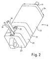
- FIG. 2 shows a pneumatic unit 8, which, as stated above, only two ports, a pneumatic port 18 and an electrical connection 19 has.
- the entire pneumatic unit 8 consists of individual assembled segments 20, 21, 22 which include the pilot valve, the pneumatic cylinder and the connections between these two structural components. Based on FIG. 2 It is easy to see that these segments can be positively joined together with a flush surface so that the overall result is a smooth and easy-to-clean surface.
- About the end flange 23 of the cylinder-side mechanical connection is made while the end flange 24 is enforced by the piston rod 11.
- light emitting diodes and an exhaust port 26 are present, however, do not affect the advantageous embodiment of the lifting units with a smooth, flush and thus easy to clean surface.
- the LEDs are used operating states of the pneumatic unit 8, z. B. indicate the valve switching position or the end position.
- Essential is the integrated design of a pneumatic unit 8 including a pneumatic cylinder and the associated pilot valve to achieve the advantages described above.
Landscapes
- Engineering & Computer Science (AREA)
- Mechanical Engineering (AREA)
- Physics & Mathematics (AREA)
- Fluid Mechanics (AREA)
- General Engineering & Computer Science (AREA)
- Actuator (AREA)
- Fluid-Pressure Circuits (AREA)
Description
- Die Erfindung betrifft eine Verpackungsmaschine mit wenigstens einem Pneumatikantrieb nach dem Oberbegriff des Anspruchs 1.
- Bei Verpackungsmaschinen, insbesondere Schalenverschließmaschinen oder sogenannten Tiefziehmaschinen, bei denen Schalen aus Folien geformt, versiegelt und ausgeschnitten werden, sind in verschiedenen Arbeitsstationen Pneumatikantriebe im Einsatz.
- So werden beispielsweise für die Hubeinheiten in Formstationen, Versiegelungsstationen und/oder Schneidstationen Pneumatikzylinder als Antrieb verwendet, die über ein elektrisch ansteuerbares Vorsteuerventil betrieben werden. Die Vorsteuerventile für diese Pneumatikzylinder sind üblicherweise im Bereich des Schaltschranks, einem separaten Pneumatikschrank oder sogenannten Ventilinseln am Maschinenrahmen untergebracht. In all diesen Fällen ist es erforderlich, für jede Zylinderbewegung eine separate Pneumatikleitung vom Vorsteuerventil zum Pneumatikzylinder zu legen.
- So offenbart die US-Patentschrift
US 4,711,070 eine Verpackungsmaschine gemäß dem Oberbegriff des Anspruchs 1 zum Verpacken von pulverförmigen Produkten in Tüten, wobei eine Vielzahl von Pneumatikantriebe vorgesehen sind, die einzeln mit separaten Leitungen an eine Vielzahl von gemeinsam angeordneten Vorsteuerventilen angeschlossen sind. - Die internationale Patentanmeldung
WO 02/068828 A1 - Die vorgenannten pneumatischen Systeme sind dabei jeweils schwer zu reinigen, da sie einzeln über Leitungen an eine Pneumatikversorgung beziehungsweise -steuerung angeschlossen werden müssen, beziehungsweise eine äußere Form aufweisen, die schwer zu reinigen ist.
- In der
WO 2005/042349 A1 wird ausgeführt, dass sich im Bereich der Lebensmittel- und Medizintechnikindustrie aufgrund der immer höheren Hygienestandards bei Verpackungsmaschinen pneumatisch angetriebene Zylinder als unvorteilhaft erwiesen hätten, und demzufolge wird eine Verpackungsmaschine offenbart, die einen Elektrolinearantrieb aufweist. - Insbesondere im Bereich der Lebensmittelverpackung werden strenge Anforderungen an die Hygiene gestellt. Daher muss eine derartige Maschine nach Möglichkeit wenig schmutzanfällig und gut zu reinigen sein.
- Aufgabe der Erfindung ist es daher, eine schmutzunempfindliche Verpackungsmaschine vorzuschlagen, die leichter zu reinigen ist.
- Diese Aufgabe wird, ausgehend von einer Verpackungsmaschine der einleitend genannten Art, durch die kennzeichnenden Merkmale des Anspruchs 1 gelöst.
- Durch die in den Unteransprüchen genannten Maßnahmen sind vorteilhafte Ausführungen und Weiterbildungen der Erfindung möglich.
- Dementsprechend zeichnet sich eine erfindungsgemäße Verpackungsmaschine dadurch aus, dass das Vorsteuerventil und der Pneumatikzylinder zu einer integrierten Baueinheit, bzw. Pneumatikeinheit, zusammenfasst sind. Hierdurch wird die Leistungsführung der pneumatischen Leitungen in der Maschine vereinfacht. Es kann eine Pneumatikleitung an das Vorsteuerventil geführt werden, das seinerseits alle Bewegungen des Pneumatikzylinders steuert. Eine Verminderung der Leitungsanzahl und/oder -länge bedeutet zugleich eine Verringerung potentieller Schmutzfänger an der Maschine und somit eine Verbesserung der Reinigungsmöglichkeiten, was der Sauberkeit und insbesondere der Hygiene der Maschine entgegenkommt. Darüber hin-aus wird die Montage und Wartung der Maschine vereinfacht. Weiterhin wird in der erfindungsgemäßen Verpackungsmaschine eine pneumatische Ringleitung vorgesehen. Hierdurch können mit einer Leitung mehrere erfindungsgemäße integrierte Pneumatikeinheiten mit Druckluft versorgt werden. Der Leistungsaufwand bei der Montage und Wartung wird hierdurch verringert. Darüber hinaus wird die insgesamt vorhandene Leistungslänge bei einer derart aufgebauten Verpackungsmaschine weiter reduziert, was zu einer weiteren Steigerung der erfindungsgemäßen Vorteile führt.
- Vorzugweise wird diese integrierte Baueinheit aus Vorsteuerventil und Pneumatikzylinder ohne äußere Verbindungsleitung zwischen Vorsteuerventil und Pneumatikzylinder ausgestaltet, wodurch die oben genannten Vorteile im Hinblick auf verringerte Schmutzempfindlichkeit und verbesserte Reinigungsmöglichkeit weiter verbessert werden.
- Darüber hinaus wird eine erfindungsgemäße integrierte Baueinheit bevorzugt zusätzlich mit Sensoren versehen, beispielsweise mit Wegmesssystemen, Näherungssensoren und/oder Endschaltern. Derartige Sensoren werden bislang separat an der Maschine oder außen an dem Pneumatikzylinder angebracht und müssen daher auch separat mit Signal und Versorgungsleitungen versehen werden. Sowohl die Sensoren, als auch die zugehörigen Leitungen stellen potentielle Schmutzfänger dar. Durch die Integration in die erfindungsgemäße Baueinheit wird nunmehr die Anzahl der elektrischen Leitungen reduziert. Darüber hinaus können die Sensoren so angeordnet werden, dass hierdurch keine äußeren Schmutzfänger oder dergleichen entstehen. Die erfindungsgemäß zu erzielenden Vorteile werden hierdurch weiter gesteigert.
- In einer einfachen Ausführungsform der Erfindung wird die Abluft des Pneumatikzylinders in die Umgebung abgeleitet. Ja nach Anwendungsfall ist jedoch eine Führung der Abluft erforderlich. In diesem Fall wird in einer Weiterbildung der Erfindung die Leitungsführung für die Zu- und Abluft in einer doppelten pneumatischen Leitung zusammengefasst. In Frage käme hierzu beispielsweise ein doppelwandiger Schlauch, der im Inneren die komprimierte Druckluft zuführt und im Zwischenraum des doppelwandigen Schlauchs die entspannte Abluft abführt.
- In einer besonderen Ausführungsform der Erfindung werden die elektrischen und die pneumatischen Leitungen in einer gemeinsamen Leitungsführung zusammengefasst, um die erfindungsgemäßen Vorteile weiter zu steigern.
- Dies kann beispielsweise dadurch geschehen, dass die Pneumatikleitung in einer Mehrfachleitung vorgenommen wird, in die die erforderlichen elektrischen Leitungen eingelegt sind. Im Falle des oben angeführten Ausführungsbeispiels mit einer Abluftabgabe an die Umgebung kann dies beispielsweise ebenfalls mit Hilfe eines Doppelschlauchs realisiert werden. Auch ein Mehrfachschlauch mit mehr als zwei Leitungskanälen könnte beispielsweise dadurch realisiert werden, dass um einen zentralen, beispielsweise für die Druckluftzufuhr vorgesehenen Pneumatikschlauch mehrere Schläuche entlang dem Umfang angeordnet und mit einem Mantel zu einer Baueinheit zusammengehalten werden.
- Auch die elektrische Leistungsführung wird vorzugsweise in Form einer Ringleitung realisiert, um mehrere erfindungsgemäße Pneumatikeinheiten anzuschließen. Bei einer elektrischen Ringleitung ergeben sich die gleichen Vorteile, wie bei der oben angeführten pneumatischen Ringleitung, wobei in einer besonders vorteilhaften und weiter verbesserten Ausführungsform die elektrische Ringleitung und die pneumatische Ringleitung zu einer gemeinsamen Ringleitung kombiniert werden können.
- Um eine elektrische Ringleitung für mehrere erfindungsgemäße Pneumatikeinheiten zu realisieren wird bevorzugt eine Multipolleitung verwendet. In einer einfachen Ausführungsform werden hierbei für jede Pneumatikeinheit separate Adern in der Multipolleitung geführt und am entsprechenden Einsatzort aus der Multipolleitung abgezweigt.
- In einer vorteilhaften Weiterbildung der Erfindung werden die erfindungsgemäßen Pneumatikeinheiten mit einer BusSchnittstelle versehen, so dass sowohl die Versorgungs- als auch die Signalleitung bzw. Signalleitungen für die verschiedenen Pneumatikeinheiten gemeinsam verwendbar sind.
- In einer Weiterbildung der busfähigen Ausführungsform wird ein drahtloser Bus vorgesehen, so dass die integrierten Pneumatikeinheiten nur noch mit einem Pneumatikanschluss und einer elektrischen Energieversorgung zu versehen sind.
- In besonderen Anwendungsfällen kann eine erfindungsgemäß integrierte Pneumatikeinheit insbesondere in Verbindung mit einem drahtlosen Bus mit einer eigenen elektrischen Energieversorgung ausgestattet werden, beispielsweise einer Batterie oder einem Generator. Ein solcher Generator kann z.B. pneumatisch oder mechanisch über die Druckluftversorgung oder die Bewegung des Pneumatikzylinders betrieben werden, so dass in Verbindung mit einem drahtlosen Bus nur noch der Pneumatikanschluss erforderlich ist.
- Eine andere Weiterbildung der Erfindung sieht ein Vorsteuerventil in einer erfindungsgemäßen Pneumatikeinheit vor, das zur Steuerung mehrerer Pneumatikzylinder und/oder Pneumatikmotoren geeignet ist. Sofern diese zusätzlichen Pneumatikzylinder und -motoren am gleichen Einsatzort erforderlich sind, können sie ohne weiteres in die erfindungsgemäße Pneumatikeinheit mit integriert werden.
- Eine erfindungsgemäße Pneumatikeinheit kann beispielsweise in einem gemeinsamen Gehäuse für den Pneumatikzylinder und das Vorsteuerventil untergebracht werden. Hierdurch ergibt sich eine glatt und leicht zu reinigende Oberfläche.
- Eine andere, leicht zu reinigende Ausführung besteht darin, die Komponenten zu einer Kompletteinheit aneinander zu fügen, wobei vorzugsweise auf bündig abschließende Oberflächen geachtet wird.
- Vorteilhafterweise wird eine Reinigungsstellung für die in der Verpackungsmaschine vorhandenen Hubeinheiten vorgesehen. Eine solche Reinigungsstellung dient dazu, Maschinenkomponenten in eine Position zu bringen, beispielsweise die Formwerkzeuge zu schließen, in der sie von etwaigen Reinigungsmedien nicht beeinträchtigt werden.
- Die Reinigungsstellung wird bevorzugt bei abgeschalteter Maschine eingenommen. Hierzu wird vorzugsweise eine Verriegelungseinheit vorgesehen, die die Hubeinheiten in drucklosem Zustand verriegelt. Dies kann beispielsweise durch eine mechanische Verriegelung der Endlagenstellung der Pneumatikeinheiten vorgenommen werden, die durch eine in die Maschinensteuerung integrierte Steuerungsroutine betätigt wird. In Frage kommt beispielsweise ein über einen federgelagerten Kolben betätigbarer Riegel oder eine elektromechanische Baueinheit, die die Endlage der Pneumatikeinheit verriegelt. Eine drucklose Verriegelung bietet den Vorteil, dass kein separater Zusatzschlauch für die Ansteuerung der Verriegelung erforderlich ist. Im Falle einer federgelagerten Verriegelungseinheit dient die Federkraft als Antrieb zur Verriegelung, im Falle einer elektromechanischen Verriegelungseinheit kann diese über ein ohnehin vorhandenes Multipolkabel angesteuert werden.
- Ein Ausführungsbeispiel der Erfindung ist in der Zeichnung beschrieben und wird anhand der Figuren nachfolgend näher erläutert.
- Im Einzelnen zeigen
- Figur 1
- eine schematische Darstellung einer Verpackungsmaschine in der Seitenansicht und
- Figur 2
- eine schematische perspektivische Darstellung einer erfindungsgemäßen Pneumatikeinheit.
-
Figur 1 zeigt eine Verpackungsmaschine 1 in Form einer sogenannten Tiefziehmaschine. Eine Verpackungsfolie 2 wird in einer Formstation 3 unter Ausbildung einer Mulde zur Aufnahme von Packgut tiefgezogen. In einer Versiegelungsstation 4 wird eine Deckelfolie auf die mit Packgut 5 gefüllte Verpackung 6 aufgebracht. In einer darauf folgenden Schneidstation 7 werden die noch zusammenhängenden Verpackungen auseinandergeschnitten. - Sowohl in der Formstation als auch in der Versiegelungsstation und der Schneidstation sind erfindungsgemäße Pneumatikeinheiten 8, 9, 10 angeordnet, die auf nicht näher dargestellte Weise einen Pneumatikzylinder und ein Vorsteuerventil umfassen. Die Pneumatikeinheiten 8, 9, 10 dienen über die Kolbenstangen 11, 12, 13 als Hubeinheit in der jeweiligen Bearbeitungsstation 3, 4, 7. Die Hubbewegung ist jeweils durch Doppelpfeile angedeutet.
- Die Hubbewegung muss dabei nicht unmittelbar über die Kolbenstange der Hubeinheit auf die anzuhebende Maschinenkomponente übertragen werden. Je nach Anwendungsfall können hier Getriebemechanismen, beispielsweise Kniehebel, Gelenkvielecke oder dergleichen zwischengeschaltet werden, um die Hubkraft zu verstärken, um eine Führung für die Bewegung zu bewirken oder um mehrere Angriffspunkte für die Hubkraft an der anzuhebenden Komponente, z.B. einer Form der Formstation 3 auszubilden.
- Weiterhin umfassen die Pneumatikeinheiten 8, 9, 10 schematisch dargestellte Sensoren 14 zur Erfassung der Endlage.
- Wie in
Figur 1 unschwer erkennbar ist, ist es durch die integrierte Bauweise der Pneumatikeinheiten 8, 9, 10 möglich, die Pneumatikeinheit 8, 9, 10 ausgehend von einer Ringleitung 15, gegebenenfalls über eine Stichleitung 16, mit der erforderlichen Druckluft zu versorgen. Durch die integrierte Bauweise ist nur ein Pneumatikanschluss für jede Pneumatikeinheit 8, 9, 10 erforderlich. - Ebenso ist für jede Pneumatikeinheit 8, 9, 10 jeweils nur eine elektrische Leitung 17 erforderlich, die in Form eines mehrpoligen Kabels sowohl die Energieversorgung als auch Signalleitung für das Vorsteuerventil sowie für die Sensoren 14 beinhaltet.
- Anhand von
Figur 1 ist erkennbar, dass durch die integrierte Bauweise der Pneumatikeinheiten 8, 9, 10 die Anzahl der Leitungen und somit auch die insgesamt benötigte Leitungslänge deutlich reduziert wird. Hierdurch ergeben sich die erfindungsgemäßen Vorteile im Hinblick auf die Schmutzempfindlichkeit und die Reinigungsfreundlichkeit. Weiterhin wird die Montage und der Aufbau der Verpackungsmaschine 1 hierdurch erleichtert. -
Figur 2 zeigt eine Pneumatikeinheit 8, die wie oben ausgeführt lediglich zwei Anschlüsse, einen Pneumatikanschluss 18 und einen elektrischen Anschluss 19 aufweist. Die gesamte Pneumatikeinheit 8 besteht aus einzelnen zusammengefügten Segmenten 20, 21, 22 die das Vorsteuerventil, die Pneumatikzylinder sowie die Verbindungen zwischen diesen beiden Baukomponenten beinhalten. Anhand vonFigur 2 ist unschwer erkennbar, dass diese Segmente formschlüssig mit bündiger Oberfläche so zusammengefügt werden können, dass sich insgesamt eine glatte und gut zu reinigende Oberfläche ergibt. Über den Endflansch 23 wird der zylinderseitige mechanische Anschluss hergestellt, während der Endflansch 24 von der Kolbenstange 11 durchgesetzt wird. - Weiterhin sind jedoch noch Leuchtdioden sowie eine Abluftöffnung 26 vorhanden, die jedoch die vorteilhafte Ausgestaltung der Hubeinheiten mit glatter, bündiger und somit leicht zu reinigender Oberfläche nicht beeinträchtigen. Die Leuchtdioden dienen dazu, Betriebszustände der Pneumatikeinheit 8, z. B. die Ventilschaltstellung oder die Endlage anzuzeigen.
- Neben der dargestellten Ausführungsform sind noch weitere Ausgestaltungen der Erfindung möglich. Wesentlich ist die integrierte Bauweise einer Pneumatikeinheit 8 unter Einschluss eines Pneumatikzylinders sowie des zugehörigen Vorsteuerventils, um die oben beschriebenen Vorteile zu erzielen.
-
- 1
- Verpackungsmaschine
- 2
- Verpackungsfolie
- 3
- Formstation
- 4
- Versiegelungsstation
- 5
- Packgut
- 6
- Verpackung
- 7
- Schneidstation
- 8
- Pneumatikeinheit
- 9
- Pneumatikeinheit
- 10
- Pneumatikeinheit
- 11
- Kolbenstange
- 12
- Kolbenstange
- 13
- Kolbenstange
- 14
- Sensoren
- 15
- Ringleitung
- 16
- Stichleitung
- 17
- elektrische Leitung
- 18
- Pneumatikanschluss
- 19
- elektrischer Anschluss
- 20
- Segment
- 21
- Segment
- 22
- Segment
- 23
- Endflansch
- 24
- Endflansch
- 26
- Abluftöffnung
Claims (13)
- Verpackungsmaschine mit wenigstens einem Pneumatikantrieb, der einen elektrisch über ein Vorsteuerventil steuerbaren Pneumatikzylinder umfasst,
dadurch gekennzeichnet, dass
das Vorsteuerventil und der Pneumatikzylinder als integrierte Pneumatikeinheit (8, 9, 10) ausgebildet sind, und dass in der Verpackungsmaschine (1) eine pneumatische Ringleitung (15) vorgesehen ist, mit der mehrere der integrierten Pneumatikeinheiten (8, 9, 10) mit Druckluft versorgt werden. - Verpackungsmaschihe nach Anspruch 1, dadurch gekennzeichnet, dass die integrierten Pneumatikeinheiten (8, 9, 10) interne Verbindungsleitungen zwischen Vorsteuerventil und Pneumatikzylinder aufweisen.
- Verpackungsmaschine nach einem der vorgenannten Ansprüche, dadurch gekennzeichnet, dass die Pneumatikeinheiten (8, 9, 10) integrierte Sensoren (14) umfassen.
- Verpackungsmaschine nach Anspruch 3, dadurch gekennzeichnet, dass als Sensor (14) ein Wegmesssystem, ein Näherungssensor und/oder ein Endschalter vorgesehen ist.
- Verpackungsmaschine nach einem der vorgenannten Ansprüche, dadurch gekennzeichnet, dass die pneumatische Ringleitung (15) wenigstens zwei Druckluftkanäle umfasst.
- Verpackungsmaschine nach einem der vorgenannten Ansprüche, dadurch gekennzeichnet, dass eine elektrische Leitung und die pneumatische Ringleitung (15) zu einer Mehrfachleitung zusammengefasst sind. '
- Verpackungsmaschine nach einem der vorgenanntlen Ansprüche, dadurch gekennzeichnet, dass eine elektrische Ringleitung vorgesehen ist.
- Verpackungsmaschine nach einem der vorgenannten Ansprüche, dadurch gekennzeichnet, dass als elektrische Leitung ein Multipolkabel vorgesehen ist.
- Verpackungsmaschine nach einem der vorgenannten Ansprüche, dadurch gekennzeichnet, dass jede Pneumatikeinheit (8, 9, 10) eine Schnittstelle für einen elektronischen Datenbus umfasst.
- Verpackungsmaschine nach einem der vorgenannten Ansprüche, dadurch gekennzeichnet, dass ein drahtloser Datenbus vorgesehen ist.
- Verpackungsmaschine nach einem der vorgenannten Ansprüche, dadurch gekennzeichnet, dass ein gemeinsames Gehäuse für den Pneumatikzylinder und das Vorsteuerventil vorgesehen ist.
- Verpackungsmaschine nach einem der vorgenannten Ansprüche, dadurch gekennzeichnet, dass der Pneumatikzylinder und das Vorsteuerventil zur Bildung der integrierten Pneumatikeinheit (8, 9, 10) aneinandergefügt sind.
- Verpackungsmaschine nach einem der vorgenannten Ansprüche, dadurch gekennzeichnet, dass die Pneumatikeinheit (8, 9, 10) aneinandergefügte Segmente (20, 21, 22) mit bündigen Oberflächen aufweist.
Applications Claiming Priority (2)
| Application Number | Priority Date | Filing Date | Title |
|---|---|---|---|
| DE102005038357A DE102005038357A1 (de) | 2005-08-11 | 2005-08-11 | Verpackungsmaschine mit wenigstens einem Pneumatikantrieb |
| PCT/DE2006/001251 WO2007019818A1 (de) | 2005-08-11 | 2006-07-18 | Verpackungsmaschine mit wenigstens einem pneumatikantrieb |
Publications (2)
| Publication Number | Publication Date |
|---|---|
| EP1912864A1 EP1912864A1 (de) | 2008-04-23 |
| EP1912864B1 true EP1912864B1 (de) | 2012-09-05 |
Family
ID=37140649
Family Applications (1)
| Application Number | Title | Priority Date | Filing Date |
|---|---|---|---|
| EP06775708A Not-in-force EP1912864B1 (de) | 2005-08-11 | 2006-07-18 | Verpackungsmaschine mit wenigstens einem pneumatikantrieb |
Country Status (4)
| Country | Link |
|---|---|
| US (1) | US20100107572A1 (de) |
| EP (1) | EP1912864B1 (de) |
| DE (1) | DE102005038357A1 (de) |
| WO (1) | WO2007019818A1 (de) |
Families Citing this family (13)
| Publication number | Priority date | Publication date | Assignee | Title |
|---|---|---|---|---|
| AU2004100000A4 (en) | 2004-01-02 | 2004-02-12 | Sands Innovations Pty Ltd | Dispensing stirring implement |
| EP2015996B2 (de) * | 2006-05-05 | 2019-07-17 | MULTIVAC Sepp Haggenmüller SE & Co. KG | Verpackungsmaschine, insbesondere umfassend eine tiefziehmaschine |
| AU2008210267B2 (en) | 2007-01-31 | 2014-06-12 | Sands Innovations Pty Ltd | A dispensing utensil and manufacturing method therefor |
| AU2008365185B2 (en) | 2008-12-09 | 2016-05-05 | Sands Innovations Pty Ltd | A dispensing container |
| USD636890S1 (en) | 2009-09-17 | 2011-04-26 | Sands Innovations Pty. Ltd. | Dispensing utensil |
| WO2011050969A2 (en) * | 2009-10-29 | 2011-05-05 | Norgren Gmbh | Fluid operated actuator |
| DE102010019636A1 (de) * | 2010-05-06 | 2011-11-10 | Multivac Sepp Haggenmüller Gmbh & Co. Kg | Verpackungsmaschine und -verfahren mit Drucklufterzeugung |
| US8511500B2 (en) | 2010-06-07 | 2013-08-20 | Sands Innovations Pty. Ltd. | Dispensing container |
| ES2411957T3 (es) * | 2010-07-29 | 2013-07-09 | Multivac Sepp Haggenmüller Gmbh & Co Kg | Máquina de envasado con varias estaciones de trabajo |
| US8485360B2 (en) | 2011-03-04 | 2013-07-16 | Sands Innovations Pty, Ltd. | Fracturable container |
| DE102014226830B4 (de) * | 2014-12-22 | 2016-11-24 | Multivac Sepp Haggenmüller Se & Co. Kg | Verpackungsmaschine mit hygienischem Pneumatikzylinder |
| DE102016102954A1 (de) * | 2016-02-19 | 2017-08-24 | Multivac Sepp Haggenmüller Se & Co. Kg | Vakuumpumpe |
| DE102016107393A1 (de) * | 2016-04-21 | 2017-10-26 | Festo Ag & Co. Kg | Modulares Antriebssystem |
Family Cites Families (26)
| Publication number | Priority date | Publication date | Assignee | Title |
|---|---|---|---|---|
| CH340180A (fr) * | 1956-08-10 | 1959-07-31 | Seab | Machine automatique pour le conditionnement d'un produit |
| US4285639A (en) * | 1979-06-12 | 1981-08-25 | Parker-Hannifin Corporation | Electronic control for variable displacement pumps |
| US4638444A (en) * | 1983-02-17 | 1987-01-20 | Chemical Data Systems, Inc. | Microprocessor-controlled back-pressure system for small volume chemical analysis applications |
| FR2570674B1 (fr) * | 1984-08-22 | 1987-07-17 | Atochem | Perfectionnements aux machines de conditionnement de matieres pulverulentes dans les sacs a valve a l'aide de placeurs de sacs |
| US4666394A (en) * | 1985-02-07 | 1987-05-19 | Mitsubishi Jukogyo Kabushiki Kaisha | Apparatus for thermally fixing the formed thermoplastic products |
| CH666455A5 (de) * | 1985-02-18 | 1988-07-29 | Ilapak Res & Dev Sa | Verschliessvorrichtung an einer schlauchbeutelmaschine mit schweiss- und/oder siegelbacken. |
| DE4216208C2 (de) * | 1992-05-15 | 1997-02-13 | Multivac Haggenmueller Kg | Verpackungsmaschine mit einem Ventil und einer Steuerung zum Steuern des Ventils |
| FR2712253B1 (fr) * | 1993-11-10 | 1996-01-19 | Mecaplastic | Procédé et dispositif de conditionnement de produits alimentaires, chimiques ou pharmaceutiques et barquettes de conditionnement correspondantes. |
| JP3473861B2 (ja) * | 1993-12-28 | 2003-12-08 | 株式会社イシダ | 包材の封止部に介在する介在物の有無の判定方法 |
| DE59709858D1 (de) * | 1997-08-08 | 2003-05-22 | Multivac Haggenmueller Kg | Hubeinrichtung für eine Arbeitsstation einer Verpackungsmaschine |
| AT410291B (de) * | 1997-08-18 | 2003-03-25 | Walter Sticht | Bewegungseinheit |
| FR2772001B1 (fr) * | 1997-12-04 | 2000-02-25 | Cefma | Procede et installation pour reunir en lots des articles alignes, au moyen de troncons de bandes adhesives avec rabats |
| DE29818075U1 (de) * | 1998-10-09 | 1998-12-24 | Kuhnke GmbH, 23714 Malente | Fluidischer Aktuator |
| US6443721B1 (en) * | 1999-05-05 | 2002-09-03 | Maytag Corporation | Apparatus for creating a substantially uniform temperature across a plastic sheet for delivery to an appliance liner thermoforming device |
| CN1307256A (zh) * | 2000-02-03 | 2001-08-08 | 中国石油天然气股份有限公司独山子分公司 | 一种仿人智能调节器 |
| US6314991B1 (en) * | 2000-03-02 | 2001-11-13 | Rajinder S. Gill | Mass flow controller |
| IT1321261B1 (it) * | 2000-05-16 | 2004-01-08 | Techne Technipack Engineering | Apparato per la depressurizzazione interna dei contenitori di materiaplastica termoformati per soffiaggio e destinati al confezionamento |
| WO2002068828A1 (de) * | 2001-02-22 | 2002-09-06 | Festo Ag & Co | Arbeitszylinder |
| DE20103579U1 (de) * | 2001-02-22 | 2001-05-10 | Festo AG & Co, 73734 Esslingen | Arbeitszylinder |
| US7070161B2 (en) * | 2003-09-11 | 2006-07-04 | Continental Hydraulics | Proportional directional control valve with a magnetic positioning sensor |
| DE10351567B4 (de) * | 2003-11-03 | 2017-06-22 | Gea Food Solutions Germany Gmbh | Thermoformer mit einem Elektrolinearzylinder |
| DE202004014520U1 (de) * | 2004-09-17 | 2004-11-18 | Festo Ag & Co. | Fluidbetätigter Arbeitszylinder |
| US7509975B2 (en) * | 2005-04-19 | 2009-03-31 | Enginuity, Inc. | Fluid sensing shut-off devices with timer and methods of operation |
| EP2015996B2 (de) * | 2006-05-05 | 2019-07-17 | MULTIVAC Sepp Haggenmüller SE & Co. KG | Verpackungsmaschine, insbesondere umfassend eine tiefziehmaschine |
| DE102007031527B3 (de) * | 2007-07-06 | 2008-06-19 | Multivac Sepp Haggenmüller Gmbh & Co. Kg | Verpackungsmaschine und Verfahren zum Herstellen von Packungen aus einer Folie |
| DE102008035994A1 (de) * | 2008-08-01 | 2010-02-11 | Multivac Sepp Haggenmüller Gmbh & Co. Kg | Verpackungsmaschine mit einer Ultraschallvorrichtung |
-
2005
- 2005-08-11 DE DE102005038357A patent/DE102005038357A1/de not_active Withdrawn
-
2006
- 2006-07-18 WO PCT/DE2006/001251 patent/WO2007019818A1/de not_active Ceased
- 2006-07-18 US US11/990,183 patent/US20100107572A1/en not_active Abandoned
- 2006-07-18 EP EP06775708A patent/EP1912864B1/de not_active Not-in-force
Also Published As
| Publication number | Publication date |
|---|---|
| DE102005038357A1 (de) | 2007-02-15 |
| WO2007019818A1 (de) | 2007-02-22 |
| EP1912864A1 (de) | 2008-04-23 |
| US20100107572A1 (en) | 2010-05-06 |
Similar Documents
| Publication | Publication Date | Title |
|---|---|---|
| EP0355179B1 (de) | Linear-Antriebseinrichtung | |
| WO2007019818A1 (de) | Verpackungsmaschine mit wenigstens einem pneumatikantrieb | |
| EP2051352B1 (de) | Elektrische Linearantriebsvorrichtung | |
| EP2072961B1 (de) | Sensor | |
| EP0442033A1 (de) | Ventilbaugruppe | |
| EP3384191A1 (de) | Ventilvorrichtung | |
| EP0017779A1 (de) | Druckmittelbetätigte Lineareinheit für Handhabungsgeräte der industriellen Fertigung | |
| EP1274945A1 (de) | Arbeitszylinder | |
| EP3405699A1 (de) | Aktuator mit einer rückensteifen kette | |
| DE69705566T2 (de) | Pneumatischer Stellantrieb mit endmontierter Steuervorrichtung | |
| EP1353257B1 (de) | Steuergriff mit Betätigungseinheiten | |
| EP0962663A2 (de) | Steuereinricthung für fluidbetätigte Verbraucher | |
| DE9211109U1 (de) | Elektro-pneumatische Steuereinrichtung | |
| EP0629783B1 (de) | Kombinierte Steuerung von Pneumatik- und Hydraulikventilen | |
| EP4159363B1 (de) | Werkzeug zum wiederholten zuführen einzelner befestigungselemente aus einem vorrat mit mehreren befestigungselementen | |
| DE102004037004A1 (de) | Anhaltevorrichtung | |
| EP0713980A2 (de) | Antriebsvorrichtung | |
| EP0930130B1 (de) | Spannvorrichtung | |
| DE102009008367A1 (de) | Vorrichtung und Verfahren zur Betätigung einer bewegbaren Komponente | |
| EP2746593A1 (de) | Ventilanordnung | |
| EP0678884A1 (de) | Schalterbetätigungseinheit | |
| DE102011015249B4 (de) | Bearbeitungsmaschine | |
| DE4004738A1 (de) | Greiferbaugruppe | |
| DE102018131914B4 (de) | Werkzeugvorrichtung umfassend zumindest eine Gasdruckfeder | |
| DE10210635B4 (de) | Explosionsgeschütztes Gehäuse mit modularem Vorsatzgehäuse |
Legal Events
| Date | Code | Title | Description |
|---|---|---|---|
| PUAI | Public reference made under article 153(3) epc to a published international application that has entered the european phase |
Free format text: ORIGINAL CODE: 0009012 |
|
| 17P | Request for examination filed |
Effective date: 20080116 |
|
| AK | Designated contracting states |
Kind code of ref document: A1 Designated state(s): AT BE BG CH CY CZ DE DK EE ES FI FR GB GR HU IE IS IT LI LT LU LV MC NL PL PT RO SE SI SK TR |
|
| 17Q | First examination report despatched |
Effective date: 20081218 |
|
| GRAP | Despatch of communication of intention to grant a patent |
Free format text: ORIGINAL CODE: EPIDOSNIGR1 |
|
| DAX | Request for extension of the european patent (deleted) | ||
| GRAS | Grant fee paid |
Free format text: ORIGINAL CODE: EPIDOSNIGR3 |
|
| GRAA | (expected) grant |
Free format text: ORIGINAL CODE: 0009210 |
|
| RAP1 | Party data changed (applicant data changed or rights of an application transferred) |
Owner name: MULTIVAC SEPP HAGGENMUELLER GMBH & CO. KG |
|
| AK | Designated contracting states |
Kind code of ref document: B1 Designated state(s): AT BE BG CH CY CZ DE DK EE ES FI FR GB GR HU IE IS IT LI LT LU LV MC NL PL PT RO SE SI SK TR |
|
| REG | Reference to a national code |
Ref country code: GB Ref legal event code: FG4D Free format text: NOT ENGLISH |
|
| REG | Reference to a national code |
Ref country code: CH Ref legal event code: EP |
|
| REG | Reference to a national code |
Ref country code: AT Ref legal event code: REF Ref document number: 573989 Country of ref document: AT Kind code of ref document: T Effective date: 20120915 |
|
| REG | Reference to a national code |
Ref country code: IE Ref legal event code: FG4D Free format text: LANGUAGE OF EP DOCUMENT: GERMAN |
|
| REG | Reference to a national code |
Ref country code: DE Ref legal event code: R096 Ref document number: 502006011946 Country of ref document: DE Effective date: 20121025 |
|
| REG | Reference to a national code |
Ref country code: NL Ref legal event code: VDEP Effective date: 20120905 |
|
| PG25 | Lapsed in a contracting state [announced via postgrant information from national office to epo] |
Ref country code: CY Free format text: LAPSE BECAUSE OF FAILURE TO SUBMIT A TRANSLATION OF THE DESCRIPTION OR TO PAY THE FEE WITHIN THE PRESCRIBED TIME-LIMIT Effective date: 20120905 Ref country code: LT Free format text: LAPSE BECAUSE OF FAILURE TO SUBMIT A TRANSLATION OF THE DESCRIPTION OR TO PAY THE FEE WITHIN THE PRESCRIBED TIME-LIMIT Effective date: 20120905 Ref country code: FI Free format text: LAPSE BECAUSE OF FAILURE TO SUBMIT A TRANSLATION OF THE DESCRIPTION OR TO PAY THE FEE WITHIN THE PRESCRIBED TIME-LIMIT Effective date: 20120905 |
|
| REG | Reference to a national code |
Ref country code: LT Ref legal event code: MG4D Effective date: 20120905 |
|
| PG25 | Lapsed in a contracting state [announced via postgrant information from national office to epo] |
Ref country code: SI Free format text: LAPSE BECAUSE OF FAILURE TO SUBMIT A TRANSLATION OF THE DESCRIPTION OR TO PAY THE FEE WITHIN THE PRESCRIBED TIME-LIMIT Effective date: 20120905 Ref country code: LV Free format text: LAPSE BECAUSE OF FAILURE TO SUBMIT A TRANSLATION OF THE DESCRIPTION OR TO PAY THE FEE WITHIN THE PRESCRIBED TIME-LIMIT Effective date: 20120905 Ref country code: GR Free format text: LAPSE BECAUSE OF FAILURE TO SUBMIT A TRANSLATION OF THE DESCRIPTION OR TO PAY THE FEE WITHIN THE PRESCRIBED TIME-LIMIT Effective date: 20121206 Ref country code: SE Free format text: LAPSE BECAUSE OF FAILURE TO SUBMIT A TRANSLATION OF THE DESCRIPTION OR TO PAY THE FEE WITHIN THE PRESCRIBED TIME-LIMIT Effective date: 20120905 |
|
| PG25 | Lapsed in a contracting state [announced via postgrant information from national office to epo] |
Ref country code: IS Free format text: LAPSE BECAUSE OF FAILURE TO SUBMIT A TRANSLATION OF THE DESCRIPTION OR TO PAY THE FEE WITHIN THE PRESCRIBED TIME-LIMIT Effective date: 20130105 Ref country code: CZ Free format text: LAPSE BECAUSE OF FAILURE TO SUBMIT A TRANSLATION OF THE DESCRIPTION OR TO PAY THE FEE WITHIN THE PRESCRIBED TIME-LIMIT Effective date: 20120905 Ref country code: NL Free format text: LAPSE BECAUSE OF FAILURE TO SUBMIT A TRANSLATION OF THE DESCRIPTION OR TO PAY THE FEE WITHIN THE PRESCRIBED TIME-LIMIT Effective date: 20120905 Ref country code: RO Free format text: LAPSE BECAUSE OF FAILURE TO SUBMIT A TRANSLATION OF THE DESCRIPTION OR TO PAY THE FEE WITHIN THE PRESCRIBED TIME-LIMIT Effective date: 20120905 Ref country code: ES Free format text: LAPSE BECAUSE OF FAILURE TO SUBMIT A TRANSLATION OF THE DESCRIPTION OR TO PAY THE FEE WITHIN THE PRESCRIBED TIME-LIMIT Effective date: 20121216 Ref country code: EE Free format text: LAPSE BECAUSE OF FAILURE TO SUBMIT A TRANSLATION OF THE DESCRIPTION OR TO PAY THE FEE WITHIN THE PRESCRIBED TIME-LIMIT Effective date: 20120905 |
|
| PG25 | Lapsed in a contracting state [announced via postgrant information from national office to epo] |
Ref country code: PT Free format text: LAPSE BECAUSE OF FAILURE TO SUBMIT A TRANSLATION OF THE DESCRIPTION OR TO PAY THE FEE WITHIN THE PRESCRIBED TIME-LIMIT Effective date: 20130107 Ref country code: PL Free format text: LAPSE BECAUSE OF FAILURE TO SUBMIT A TRANSLATION OF THE DESCRIPTION OR TO PAY THE FEE WITHIN THE PRESCRIBED TIME-LIMIT Effective date: 20120905 Ref country code: SK Free format text: LAPSE BECAUSE OF FAILURE TO SUBMIT A TRANSLATION OF THE DESCRIPTION OR TO PAY THE FEE WITHIN THE PRESCRIBED TIME-LIMIT Effective date: 20120905 |
|
| PLBE | No opposition filed within time limit |
Free format text: ORIGINAL CODE: 0009261 |
|
| STAA | Information on the status of an ep patent application or granted ep patent |
Free format text: STATUS: NO OPPOSITION FILED WITHIN TIME LIMIT |
|
| PG25 | Lapsed in a contracting state [announced via postgrant information from national office to epo] |
Ref country code: BG Free format text: LAPSE BECAUSE OF FAILURE TO SUBMIT A TRANSLATION OF THE DESCRIPTION OR TO PAY THE FEE WITHIN THE PRESCRIBED TIME-LIMIT Effective date: 20121205 Ref country code: DK Free format text: LAPSE BECAUSE OF FAILURE TO SUBMIT A TRANSLATION OF THE DESCRIPTION OR TO PAY THE FEE WITHIN THE PRESCRIBED TIME-LIMIT Effective date: 20120905 |
|
| 26N | No opposition filed |
Effective date: 20130606 |
|
| REG | Reference to a national code |
Ref country code: DE Ref legal event code: R097 Ref document number: 502006011946 Country of ref document: DE Effective date: 20130606 |
|
| BERE | Be: lapsed |
Owner name: MULTIVAC SEPP HAGGENMULLER G.M.B.H. & CO. KG Effective date: 20130731 |
|
| PG25 | Lapsed in a contracting state [announced via postgrant information from national office to epo] |
Ref country code: MC Free format text: LAPSE BECAUSE OF FAILURE TO SUBMIT A TRANSLATION OF THE DESCRIPTION OR TO PAY THE FEE WITHIN THE PRESCRIBED TIME-LIMIT Effective date: 20120905 |
|
| REG | Reference to a national code |
Ref country code: CH Ref legal event code: PL |
|
| REG | Reference to a national code |
Ref country code: IE Ref legal event code: MM4A |
|
| REG | Reference to a national code |
Ref country code: FR Ref legal event code: ST Effective date: 20140331 |
|
| PG25 | Lapsed in a contracting state [announced via postgrant information from national office to epo] |
Ref country code: CH Free format text: LAPSE BECAUSE OF NON-PAYMENT OF DUE FEES Effective date: 20130731 Ref country code: LI Free format text: LAPSE BECAUSE OF NON-PAYMENT OF DUE FEES Effective date: 20130731 Ref country code: BE Free format text: LAPSE BECAUSE OF NON-PAYMENT OF DUE FEES Effective date: 20130731 |
|
| PG25 | Lapsed in a contracting state [announced via postgrant information from national office to epo] |
Ref country code: FR Free format text: LAPSE BECAUSE OF NON-PAYMENT OF DUE FEES Effective date: 20130731 |
|
| PG25 | Lapsed in a contracting state [announced via postgrant information from national office to epo] |
Ref country code: IE Free format text: LAPSE BECAUSE OF NON-PAYMENT OF DUE FEES Effective date: 20130718 |
|
| REG | Reference to a national code |
Ref country code: AT Ref legal event code: MM01 Ref document number: 573989 Country of ref document: AT Kind code of ref document: T Effective date: 20130718 |
|
| PG25 | Lapsed in a contracting state [announced via postgrant information from national office to epo] |
Ref country code: AT Free format text: LAPSE BECAUSE OF NON-PAYMENT OF DUE FEES Effective date: 20130718 |
|
| PG25 | Lapsed in a contracting state [announced via postgrant information from national office to epo] |
Ref country code: TR Free format text: LAPSE BECAUSE OF FAILURE TO SUBMIT A TRANSLATION OF THE DESCRIPTION OR TO PAY THE FEE WITHIN THE PRESCRIBED TIME-LIMIT Effective date: 20120905 |
|
| PG25 | Lapsed in a contracting state [announced via postgrant information from national office to epo] |
Ref country code: HU Free format text: LAPSE BECAUSE OF FAILURE TO SUBMIT A TRANSLATION OF THE DESCRIPTION OR TO PAY THE FEE WITHIN THE PRESCRIBED TIME-LIMIT; INVALID AB INITIO Effective date: 20060718 Ref country code: LU Free format text: LAPSE BECAUSE OF NON-PAYMENT OF DUE FEES Effective date: 20130718 |
|
| REG | Reference to a national code |
Ref country code: DE Ref legal event code: R082 Ref document number: 502006011946 Country of ref document: DE Representative=s name: GRUENECKER PATENT- UND RECHTSANWAELTE PARTG MB, DE Ref country code: DE Ref legal event code: R081 Ref document number: 502006011946 Country of ref document: DE Owner name: MULTIVAC SEPP HAGGENMUELLER SE & CO. KG, DE Free format text: FORMER OWNER: MULTIVAC SEPP HAGGENMUELLER GMBH & CO. KG, 87787 WOLFERTSCHWENDEN, DE |
|
| PGFP | Annual fee paid to national office [announced via postgrant information from national office to epo] |
Ref country code: IT Payment date: 20180720 Year of fee payment: 13 Ref country code: DE Payment date: 20180725 Year of fee payment: 13 |
|
| PGFP | Annual fee paid to national office [announced via postgrant information from national office to epo] |
Ref country code: GB Payment date: 20180725 Year of fee payment: 13 |
|
| REG | Reference to a national code |
Ref country code: DE Ref legal event code: R119 Ref document number: 502006011946 Country of ref document: DE |
|
| GBPC | Gb: european patent ceased through non-payment of renewal fee |
Effective date: 20190718 |
|
| PG25 | Lapsed in a contracting state [announced via postgrant information from national office to epo] |
Ref country code: GB Free format text: LAPSE BECAUSE OF NON-PAYMENT OF DUE FEES Effective date: 20190718 Ref country code: DE Free format text: LAPSE BECAUSE OF NON-PAYMENT OF DUE FEES Effective date: 20200201 |
|
| PG25 | Lapsed in a contracting state [announced via postgrant information from national office to epo] |
Ref country code: IT Free format text: LAPSE BECAUSE OF NON-PAYMENT OF DUE FEES Effective date: 20190718 |