EP1912816B1 - Procede de commande d'un pretensionneur de ceinture et systeme de securite d'un pretensionneur de ceinture - Google Patents
Procede de commande d'un pretensionneur de ceinture et systeme de securite d'un pretensionneur de ceinture Download PDFInfo
- Publication number
- EP1912816B1 EP1912816B1 EP06776179A EP06776179A EP1912816B1 EP 1912816 B1 EP1912816 B1 EP 1912816B1 EP 06776179 A EP06776179 A EP 06776179A EP 06776179 A EP06776179 A EP 06776179A EP 1912816 B1 EP1912816 B1 EP 1912816B1
- Authority
- EP
- European Patent Office
- Prior art keywords
- turning rate
- vehicle
- speed
- motor vehicle
- limiting value
- Prior art date
- Legal status (The legal status is an assumption and is not a legal conclusion. Google has not performed a legal analysis and makes no representation as to the accuracy of the status listed.)
- Not-in-force
Links
Images


Classifications
-
- B—PERFORMING OPERATIONS; TRANSPORTING
- B60—VEHICLES IN GENERAL
- B60R—VEHICLES, VEHICLE FITTINGS, OR VEHICLE PARTS, NOT OTHERWISE PROVIDED FOR
- B60R21/00—Arrangements or fittings on vehicles for protecting or preventing injuries to occupants or pedestrians in case of accidents or other traffic risks
- B60R21/01—Electrical circuits for triggering passive safety arrangements, e.g. airbags, safety belt tighteners, in case of vehicle accidents or impending vehicle accidents
- B60R21/013—Electrical circuits for triggering passive safety arrangements, e.g. airbags, safety belt tighteners, in case of vehicle accidents or impending vehicle accidents including means for detecting collisions, impending collisions or roll-over
- B60R21/0132—Electrical circuits for triggering passive safety arrangements, e.g. airbags, safety belt tighteners, in case of vehicle accidents or impending vehicle accidents including means for detecting collisions, impending collisions or roll-over responsive to vehicle motion parameters, e.g. to vehicle longitudinal or transversal deceleration or speed value
-
- B—PERFORMING OPERATIONS; TRANSPORTING
- B60—VEHICLES IN GENERAL
- B60R—VEHICLES, VEHICLE FITTINGS, OR VEHICLE PARTS, NOT OTHERWISE PROVIDED FOR
- B60R21/00—Arrangements or fittings on vehicles for protecting or preventing injuries to occupants or pedestrians in case of accidents or other traffic risks
- B60R21/01—Electrical circuits for triggering passive safety arrangements, e.g. airbags, safety belt tighteners, in case of vehicle accidents or impending vehicle accidents
- B60R2021/01204—Actuation parameters of safety arrangents
- B60R2021/01252—Devices other than bags
- B60R2021/01265—Seat belts
- B60R2021/01272—Belt tensioners
-
- B—PERFORMING OPERATIONS; TRANSPORTING
- B60—VEHICLES IN GENERAL
- B60R—VEHICLES, VEHICLE FITTINGS, OR VEHICLE PARTS, NOT OTHERWISE PROVIDED FOR
- B60R21/00—Arrangements or fittings on vehicles for protecting or preventing injuries to occupants or pedestrians in case of accidents or other traffic risks
- B60R21/01—Electrical circuits for triggering passive safety arrangements, e.g. airbags, safety belt tighteners, in case of vehicle accidents or impending vehicle accidents
- B60R21/013—Electrical circuits for triggering passive safety arrangements, e.g. airbags, safety belt tighteners, in case of vehicle accidents or impending vehicle accidents including means for detecting collisions, impending collisions or roll-over
- B60R2021/01313—Electrical circuits for triggering passive safety arrangements, e.g. airbags, safety belt tighteners, in case of vehicle accidents or impending vehicle accidents including means for detecting collisions, impending collisions or roll-over monitoring the vehicle steering system or the dynamic control system
-
- B—PERFORMING OPERATIONS; TRANSPORTING
- B60—VEHICLES IN GENERAL
- B60R—VEHICLES, VEHICLE FITTINGS, OR VEHICLE PARTS, NOT OTHERWISE PROVIDED FOR
- B60R21/00—Arrangements or fittings on vehicles for protecting or preventing injuries to occupants or pedestrians in case of accidents or other traffic risks
- B60R21/01—Electrical circuits for triggering passive safety arrangements, e.g. airbags, safety belt tighteners, in case of vehicle accidents or impending vehicle accidents
- B60R21/013—Electrical circuits for triggering passive safety arrangements, e.g. airbags, safety belt tighteners, in case of vehicle accidents or impending vehicle accidents including means for detecting collisions, impending collisions or roll-over
- B60R21/0132—Electrical circuits for triggering passive safety arrangements, e.g. airbags, safety belt tighteners, in case of vehicle accidents or impending vehicle accidents including means for detecting collisions, impending collisions or roll-over responsive to vehicle motion parameters, e.g. to vehicle longitudinal or transversal deceleration or speed value
- B60R2021/01327—Angular velocity or angular acceleration
Definitions
- the present invention relates to a method for controlling a reversible belt tensioner in a motor vehicle.
- the invention further relates to a safety arrangement for a motor vehicle with a reversible belt tensioner.
- Different safety arrangements for motor vehicles are known from the prior art. These regularly include a winding mechanism for automatically winding a seat belt around a belt reel. By the automatic winding is achieved that the applied seat belt loosely and comfortably rests against the body of the vehicle occupant and is rolled up when not using the seat belt to the belt reel. The unwinding of the seat belt is easily possible when wearing a seat belt, so that the freedom of movement of the vehicle occupant is guaranteed.
- belt tensioners are provided in the known safety arrangements.
- the belt tensioners cause a tightening of the seat belt to pull the vehicle occupant against the backrest of the vehicle seat, so that the risk of injury is reduced in the event of a collision of the vehicle with another vehicle or a traffic obstruction.
- the known belt tensioners can be divided into irreversible and reversible belt tensioners.
- the irreversible The belt tensioner is activated only when an accident has already occurred, such as a collision with another vehicle. Crash sensors detect the collision and send a corresponding activation signal to the irreversible belt tensioner.
- the irreversible belt tensioners can always be activated or triggered only once, since it has definitely come to an accident.
- the reversible belt tensioners should be able to be triggered several times, even in quick succession, on the basis of signals that indicate the possibility of an imminent crash. That is, the reversible belt tensioners should be able to be activated whenever a crash is possible or probable, but has not yet occurred.
- a critical driving situation is not determined by crash sensors which merely determine the crash actually taking place, but rather by driving dynamics sensors which provide information about the current state of motion of the motor vehicle. This includes, for example, the determination of the longitudinal, lateral and vertical acceleration of the motor vehicle. If these measured values exceed a limit value, the prophylactic activation of the reversible belt tensioner takes place. If the limit falls below again and no crash has actually occurred, then the reversible belt tensioner is deactivated again, so that the seat belt can be brought back into its normal position, in which the vehicle occupant has a greater freedom of movement. At the next critical driving situation, it is possible to reactivate the reversible belt tensioner again.
- the DE 199 61 799 B4 describes a safety belt system with a reversible belt tensioner.
- the known reversible belt tensioner has an electric motor drive, the safety belt in a safety intermediate position with a certain traction reversible depending on a derived from sensor signals probability of an accident situation biases.
- the critical driving situation detected by the non-explained precrash sensor system, which leads to an activation of the belt tensioner, can be, for example, a spin, a full brake, etc.
- the DE 103 45 726 A1 describes a restraint system for restraining an occupant in a vehicle.
- the well-known restraint system has a reversible belt tensioner, which is controlled by a control unit.
- the controller communicates with a vehicle situation detecting means for dynamically detecting vehicle situation data such as the lateral acceleration of the vehicle and an occupant parameter detecting means for dynamically detecting occupant parameter data such as the occupant's weight.
- the pretensioner is controlled in dependence on the determined vehicle situation data and occupant parameter data.
- the DE 102 30 483 A1 describes a method for controlling a two-stage irreversible belt tensioner.
- the longitudinal acceleration of the motor vehicle is detected and subjected to integration, wherein the integral of the acceleration is compared with a triggering threshold. If this tripping threshold is exceeded, the irreversible belt tensioner is triggered.
- the DE 103 32 024 A1 describes a method for controlling a reversible belt tensioner for releasing an activatable by an acceleration sensor Gurtauszugssperre a restraint in a motor vehicle.
- the release time for the belt pullout lock is defined as a time at which the detected acceleration falls below an acceleration threshold.
- the invention is further based on the object to provide a safety arrangement with a reversible belt tensioner with which the inventive method is executable.
- the method according to the invention for controlling a reversible belt tensioner in a motor vehicle has the following method steps. First, the speed of the motor vehicle and the steering angle of the motor vehicle is detected. Subsequently, an expected rate of rotation of the motor vehicle about its vertical axis is calculated on the basis of the detected speed and the steering angle. In this case, for example, it can be assumed that the ideal case in which the steering angle is converted exactly into the desired curve, without causing oversteer or understeer. the expected rate of rotation may be, for example, the angular velocity with respect to a rotation about the vertical axis. Subsequently, an upper and lower rotation rate limit value is calculated on the basis of the calculated expected rotation rate.
- the belt tensioner is activated.
- the method according to the invention leads to a situation-appropriate control of the belt tensioner in dangerous steering maneuvers.
- an oversteer or understeer of the motor vehicle is reliably detected by exceeding or falling below the upper or lower rotation rate limit, and leads to the activation of the belt tensioner.
- the activation of the belt tensioner is further only when the actual rate of rotation of the motor vehicle for a predetermined period of time is greater or less than the upper or lower rotation rate limit. In this way, it is ensured that the tightening of the seat belt takes place only in an actually dangerous steering maneuver. Such a dangerous steering maneuver is usually not present if the turning rate limit values are only briefly exceeded or fallen short of.
- the predetermined period of time is determined as a function of the speed of the motor vehicle.
- the predetermined time duration is lower, the higher the speed of the motor vehicle. In this way, the fact is taken into account that a short-term oversteer or understeer at a high speed of the motor vehicle is more dangerous than a short-term oversteer or understeer at a low speed.
- the predetermined period of time may, for example, decrease linearly or stepwise as the speed increases.
- the activation of the belt tensioner further only when the speed of the motor vehicle is higher than a predetermined speed limit. This could for example be set at 40 km / h.
- the upper or lower rotation rate limit value is calculated by multiplying the expected rotation rate by a first or second tolerance factor, wherein the first tolerance factor is greater and the second tolerance factor is less than one.
- the first tolerance factor could be 1.6 while the second tolerance factor is set at 0.75, for example.
- the further method step of deactivating the activated belt tensioner is provided when the actual turning rate of the motor vehicle is again smaller than the upper turning rate limit value and greater than the lower turning rate limit value.
- the safety arrangement according to the invention for a motor vehicle has a safety belt, a reversible belt tensioner, a detection device for detecting the speed, the steering angle and the actual rate of rotation of the motor vehicle and a control device by means of which the belt tensioner can be activated and deactivated. Under activating or deactivating the belt tensioner is to be understood as triggering or reversing the release.
- a calculation device is furthermore provided, by means of which an expected rate of rotation of the motor vehicle about its vertical axis from the speed and the steering angle and an upper and lower rotation rate limit can be calculated on the basis of the expected rate of rotation.
- the control device interacts with the belt tensioner in such a way that the belt tensioner is activated when the actual rate of turn of the motor vehicle is greater than the upper turning rate limit value or less than the lower turning rate limit value.
- control device cooperates with the belt tensioner such that the belt tensioner is further activated only if the actual rate of rotation of the motor vehicle for a predetermined period of time is greater or less than the upper or lower rotation rate limit.
- the predetermined period of time can be changed as a function of the speed of the motor vehicle.
- the predetermined time duration can be reduced by increasing the speed of the motor vehicle.
- control device cooperates with the belt tensioner such that the belt tensioner is further activated only when the speed of the motor vehicle is higher than a predetermined speed limit.
- the upper or lower rotation rate limit value is calculated by multiplying the expected rotation rate by a first or second tolerance factor with the aid of the calculation device, wherein the first tolerance factor is greater and the second tolerance factor is less than one.
- the activated seat belt pretensioner can be deactivated when the actual rate of turn of the motor vehicle is again smaller than the upper turning rate limit value and greater than the lower turning rate limit value.
- Fig. 1 shows a schematic representation of an embodiment of the safety arrangement 2 according to the invention.
- the safety arrangement 2 has a safety belt, not shown.
- the seat belt can be reversibly tightened by a reversible belt tensioner 4.
- the reversible belt tensioner 4 is in operative connection with a control device 6, so that the reversible belt tensioner 4 can be activated and deactivated by the control device 6.
- the safety arrangement 2 further comprises a detection device 8 for detecting the speed, the steering angle and the actual rate of rotation of the motor vehicle.
- the detection device 8 is connected to a speed sensor 10 for detecting the speed of the motor vehicle, a steering angle sensor 12 for detecting the steering angle of the motor vehicle and a yaw rate sensor 14 for detecting the actual rate of turn of the motor vehicle.
- a speed sensor 10 of the already existing in the motor vehicle speed sensor can be used.
- the steering angle sensor 12 can detect, for example, the position of the steering wheel or the position of the wheels of the motor vehicle.
- a calculation device 16 is also provided, to which the detected speeds, steering angles and actual rotation rates can be supplied.
- the calculation device 16 can calculate, on the one hand, an expected rate of rotation of the motor vehicle on the basis of the detected steering angle and the speed of the motor vehicle.
- the calculation unit 16 can calculate an upper and lower rotation rate limit value on the basis of the expected rotation rate. In this case, the calculation device 16 uses so-called tolerance factors.
- the thus acquired and calculated data can be transmitted to the control device 6, where an evaluation of the data takes place.
- the belt tensioner 4 is only activated by the control device 6 when the speed of the motor vehicle is higher than a predetermined speed limit, the actual turning rate of the motor vehicle is greater than the upper turning rate limit value or less than the lower turning rate limit value and the actual turning rate of the motor vehicle for a predetermined Time is greater or less than the upper or lower rotation rate limit.
- the predetermined time duration is the smaller the larger the Speed of the motor vehicle is.
- the detection device 8 detects the speed and the steering angle of the motor vehicle via the speed sensor 10 and the steering angle sensor 12.
- step S2 the calculation device 16 calculates the expected rate of turn of the motor vehicle about its vertical axis. This is easily possible on the basis of the detected steering angle and the detected speed of the motor vehicle. In the calculation of the expected rate of rotation is therefore assumed the ideal case, namely that the motor vehicle follows the desired steering direction without being over- or understeered.
- an upper and lower rotation rate limit is now determined. The upper yaw rate limit is calculated by multiplying the expected yaw rate by a first tolerance factor of 1, 6, and the lower yaw rate limit is calculated by multiplying the expected yaw rate by a second tolerance factor of 0.75. In this way, over the time an envelope is formed around the expected rate of turn, to which later in Fig. 3 will be discussed in more detail.
- the detection device 8 detects the actual rotation rate of the motor vehicle via the rotation rate sensor 14. It should be noted that both the actual rate of rotation and the steering angle and the speed of the motor vehicle are continuously detected in order to obtain the corresponding o. G. To calculate values.
- step S4 a query is carried out as to whether the detected speed of the motor vehicle is higher is a predetermined speed limit set at 40 km / h in the present example. If this is not the case, step S1 is started again. However, if the detected speed is above the speed limit, then the method step S5 is continued.
- method step S5 the query is then carried out as to whether the actual rate of rotation of the motor vehicle is greater than the upper rotation rate limit value or less than the lower rotation rate limit value. If this is not the case, then the procedure starts again in method step S1. Otherwise, the method step S6 is continued.
- step S6 a query is again performed, namely, it is checked whether the actual rate of rotation of the motor vehicle for a predetermined period of time is greater or less than the upper or lower yaw rate limit. If this is not the case, steps S1 to S5 are first of all repeated in order subsequently to check again, after time has elapsed, again in step S6, as to whether the predetermined period of time has meanwhile been exceeded. If the predetermined time period has been reached or exceeded, the method step S7 is continued.
- method step S7 the control device 6 sends a corresponding signal to the belt tensioner 4, which is then activated so that the seat belt is tightened.
- method step S8 it is checked whether the actual rate of rotation of the motor vehicle has again become smaller than the upper rotation rate limit value and greater than the lower rotation rate limit value. If this is not the case, then the belt tensioner 4 remains activated, otherwise the deactivation of the belt tensioner takes place in method step S9 before the procedure starts again in method step S1.
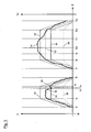
- Fig. 3 is on the axis X
- the travel time on the axis Y 1 is the actual rate of rotation and the upper turning rate limiting value, the lower turning rate limiting value and the expected turning rate, and plotted on the Y axis 2 of the steering angle
- the reference numeral 18 the course of the actual yaw rate
- the reference numeral 20 the course of the expected rate of turn
- the reference numerals 22 and 24 the course of the upper or lower rotation rate limit and the reference numeral 26 denotes the course of the steering angle. It is assumed that the motor vehicle moves over the entire time at a speed which is above the predetermined speed limit value.
- the motor vehicle drives without the driver performing a steering maneuver.
- the driver begins to turn on the steering wheel until it has reached the desired steering position at time t 3 .
- the expected rate of turn 20 of the motor vehicle also increases, the curve of the expected rate of rotation 20 always being surrounded by an envelope which is composed of the upper rate of rotation limit 22 and the lower rate of rotation limit 24.
- the motor vehicle understeers - for example by the deflected wheels slip on the road - so strong that the actual rate of rotation 18 is smaller than the lower rotation rate limit 24.
- the duration between the times t 3 and t 4 is less than the predetermined period of time, so that the belt tensioner 4 is not activated.
- the driver returns the steering wheel from the deflected position back to the original position and moves until time t 7 only straight ahead without hitting the steering wheel.
- the driver performs the same steering movement as between the times t 1 and t 6 .
- This time however, it comes on the basis of the road condition o. ⁇ . But to the fact that the motor vehicle oversteers by the rear of the same breaks.
- the actual yaw rate 18 between the times t 9 and t 11 is greater than the upper yaw rate limit value 22.
- the predetermined time period in which the actual rate of rotation may be greater than the upper rotation rate limit, exceeded, ie at time t 10 of the belt tensioner 4 is activated.
Landscapes
- Engineering & Computer Science (AREA)
- Mechanical Engineering (AREA)
- Automotive Seat Belt Assembly (AREA)
- Preliminary Treatment Of Fibers (AREA)
Claims (14)
- Procédé pour la commande d'un tendeur de ceinture réversible dans un véhicule à moteur, comprenant les étapes de procédé suivantes :détection de la vitesse et de l'angle de direction du véhicule à moteur,calcul d'une vitesse de lacet attendue du véhicule à moteur autour de son axe vertical à partir de la vitesse et de l'angle de direction,calcul d'une limite supérieure de vitesse de lacet et d'une limite inférieure à l'aide de la vitesse de lacet attendue,détection de la vitesse de lacet réelle du véhicule à moteur autour de son axe vertical,activation du tendeur de ceinture quand la vitesse de lacet réelle du véhicule à moteur est supérieure à la limite supérieure de vitesse de lacet ou inférieure à la limite inférieure de vitesse de lacet.
- Procédé selon la revendication 1, caractérisé en ce que l'activation du tendeur de ceinture n'a lieu en outre que quand la vitesse de lacet réelle du véhicule à moteur est supérieure à la limite supérieure de vitesse de lacet ou inférieure à la limite inférieure de vitesse de lacet pendant une durée prédéterminée.
- Procédé selon la revendication 2, caractérisé en ce que la durée prédéterminée est fixée en fonction de la vitesse du véhicule à moteur.
- Procédé selon la revendication 3, caractérisé en ce que la durée prédéterminée est d'autant plus courte que la vitesse du véhicule à moteur est grande.
- Procédé selon l'une des revendications 1 à 4, caractérisé en ce que l'activation du tendeur de ceinture n'a lieu en outre que quand la vitesse du véhicule à moteur est supérieure à une limite de vitesse prédéterminée.
- Procédé selon l'une des revendications précédentes, caractérisé en ce que les limites supérieure et inférieure de vitesse de lacet sont calculées par multiplication de la vitesse de lacet attendue par un premier et un deuxième facteur de tolérance, respectivement, le premier facteur de tolérance étant supérieur à 1 et le deuxième facteur de tolérance inférieur à 1.
- Procédé selon l'une des revendications comprenant en outre l'étape de procédé de désactivation du tendeur de ceinture activé quand la vitesse de lacet réelle du véhicule à moteur est à nouveau inférieure à la limite supérieure de vitesse de lacet et supérieure à la limite inférieure de vitesse de lacet.
- Dispositif de sécurité pour un véhicule à moteur avec une ceinture de sécurité, un tendeur de ceinture réversible (4), un dispositif de détection (8) pour capter la vitesse, l'angle de direction (26) et la vitesse de lacet réelle (18) du véhicule à moteur et un dispositif de commande (6) au moyen duquel le tendeur de ceinture (4) peut être activé et désactivé, caractérisé en ce qu'il est prévu un dispositif de calcul (16) au moyen duquel une vitesse de lacet attendue (20) du véhicule à moteur autour de son axe vertical peut être calculée à partir de la vitesse et de l'angle de direction (26) et des limites supérieure et inférieure de vitesse de lacet (22, 24) à partir de la vitesse de lacet attendue (20), le dispositif de commande (6) coopérant avec le tendeur de ceinture (4) de telle façon que le tendeur de ceinture (4) puisse être activé quand la vitesse de lacet réelle (18) du véhicule à moteur est supérieure à la limite supérieure de vitesse de lacet (22) ou inférieure à la limite inférieure de vitesse de lacet (24).
- Dispositif de sécurité selon la revendication 8, caractérisé en ce que le tendeur de ceinture (4) ne peut en outre être activé que quand la vitesse de lacet réelle (18) du véhicule à moteur est supérieure à la limite supérieure ou inférieure à la limite inférieure de vitesse de lacet (22, 24) pendant une durée prédéterminée.
- Dispositif de sécurité selon la revendication 9, caractérisé en ce que la durée prédéterminée peut être modifiée en fonction de la vitesse du véhicule à moteur.
- Dispositif de sécurité selon la revendication 10, caractérisé en ce que la durée prédéterminée peut être réduite par l'augmentation de la vitesse du véhicule à moteur.
- Dispositif de sécurité selon l'une des revendications 8 à 11, caractérisé en ce que le tendeur de ceinture (4) ne peut en outre être activé que quand la vitesse du véhicule à moteur est supérieure à une limite de vitesse prédéterminée.
- Dispositif de sécurité selon l'une des revendications 8 à 12, caractérisé en ce que la limite supérieure et la limite inférieure de vitesse de lacet (22, 24) peuvent être calculées par multiplication de la vitesse de lacet attendue (20) par un premier facteur de tolérance et un deuxième, respectivement, le premier facteur de tolérance étant supérieur à 1 et le deuxième facteur de tolérance inférieur à 1.
- Dispositif de sécurité selon l'une des revendications 8 à 13, caractérisé en ce que le tendeur de ceinture (4) activé peut être désactivé quand la vitesse de lacet réelle (18) du véhicule à moteur est à nouveau inférieure à la limite supérieure de vitesse de lacet (22) et supérieure à la limite inférieure de vitesse de lacet (24).
Applications Claiming Priority (2)
| Application Number | Priority Date | Filing Date | Title |
|---|---|---|---|
| DE102005035862A DE102005035862A1 (de) | 2005-07-30 | 2005-07-30 | Verfahren zur Steuerung eines Gurtstraffers und Sicherheitsanordnung mit einem Gurtstraffer |
| PCT/EP2006/006748 WO2007014627A1 (fr) | 2005-07-30 | 2006-07-11 | Procede de commande d'un pretensionneur de ceinture et systeme de securite d'un pretensionneur de ceinture |
Publications (2)
| Publication Number | Publication Date |
|---|---|
| EP1912816A1 EP1912816A1 (fr) | 2008-04-23 |
| EP1912816B1 true EP1912816B1 (fr) | 2010-09-22 |
Family
ID=36997699
Family Applications (1)
| Application Number | Title | Priority Date | Filing Date |
|---|---|---|---|
| EP06776179A Not-in-force EP1912816B1 (fr) | 2005-07-30 | 2006-07-11 | Procede de commande d'un pretensionneur de ceinture et systeme de securite d'un pretensionneur de ceinture |
Country Status (8)
| Country | Link |
|---|---|
| US (1) | US8335614B2 (fr) |
| EP (1) | EP1912816B1 (fr) |
| JP (1) | JP2009502637A (fr) |
| CN (1) | CN101233019B (fr) |
| AT (1) | ATE482103T1 (fr) |
| AU (1) | AU2006275180A1 (fr) |
| DE (2) | DE102005035862A1 (fr) |
| WO (1) | WO2007014627A1 (fr) |
Families Citing this family (8)
| Publication number | Priority date | Publication date | Assignee | Title |
|---|---|---|---|---|
| DE102010015549B4 (de) * | 2010-04-20 | 2020-08-13 | Werner Bernzen | Verfahren und Vorrichtung zur Ansteuerung mindestens einer reversiblen Insassenschutzvorrichtung eines Fahrzeuges |
| DE102011106247B4 (de) | 2011-07-01 | 2014-05-28 | Audi Ag | Verfahren zum Steuern eines reversiblen Gurtstraffers eines Sicherheitsgurts in einem Kraftfahrzeug |
| CN103121434A (zh) * | 2013-02-28 | 2013-05-29 | 安徽江淮汽车股份有限公司 | 安全带收紧系统及方法 |
| WO2017031435A1 (fr) * | 2015-08-20 | 2017-02-23 | Takata Protection Systems, Inc. | Alerte d'angle de véhicule ainsi que système et procédé de sécurité |
| KR102626248B1 (ko) | 2017-12-11 | 2024-01-17 | 현대자동차주식회사 | 능동형 안전 벨트 제어 장치 및 이의 제어 방법 |
| EP3636497B1 (fr) | 2018-10-12 | 2021-05-19 | Toyota Jidosha Kabushiki Kaisha | Système de retenue d'occupant pour véhicule |
| JP7172941B2 (ja) | 2019-10-07 | 2022-11-16 | トヨタ自動車株式会社 | 車両用乗員拘束システム |
| EP4404112A1 (fr) | 2023-01-23 | 2024-07-24 | Robert Bosch GmbH | Procédé et système de détection de dommages à un véhicule |
Family Cites Families (23)
| Publication number | Priority date | Publication date | Assignee | Title |
|---|---|---|---|---|
| DE19736328A1 (de) * | 1997-08-21 | 1999-02-25 | Bayerische Motoren Werke Ag | Einrichtung und Verfahren zur Steuerung von Unfallschutz-Auslöseeinrichtungen in Kraftfahrzeugen |
| DE19811865A1 (de) * | 1998-03-18 | 1999-09-23 | Siemens Ag | Verfahren zum Steuern des Betriebs von Kraftfahrzeug-Insassenschutzeinrichtungen |
| DE19910596A1 (de) * | 1999-03-10 | 2000-09-14 | Volkswagen Ag | Verfahren und Anordnung zur Auslösesteuerung von Rückhaltemitteln in einem Kraftfahrzeug |
| DE19961799B4 (de) * | 1999-12-21 | 2004-03-25 | Breed Automotive Technology, Inc., Lakeland | Passives Sicherheitssystem eines Kraftfahrzeugs |
| DE10005010C2 (de) * | 2000-02-04 | 2002-11-21 | Daimler Chrysler Ag | Verfahren und Sicherheits-Rückhalteeinrichtung zum Zurückhalten eines Insassen auf einem Fahrzeugsitz |
| DE10025260B4 (de) * | 2000-05-22 | 2004-11-25 | Conti Temic Microelectronic Gmbh | Verfahren zur Detektion von Überrollvorgängen bei Kraftfahrzeugen mit Sicherheitseinrichtungen |
| DE10029061C2 (de) * | 2000-06-13 | 2003-12-11 | Breed Automotive Tech | Rückhaltevorrichtung |
| DE10057916C2 (de) * | 2000-11-21 | 2003-04-17 | Bosch Gmbh Robert | Steuergerät für ein Rückhaltesystem in einem Kraftfahrzeug |
| DE10065518B4 (de) * | 2000-12-28 | 2004-10-14 | Robert Bosch Gmbh | Verfahren zum Auslösen von Rückhaltemitteln in einem Kraftfahrzeug |
| DE10118062C2 (de) * | 2001-04-11 | 2003-08-07 | Bosch Gmbh Robert | Verfahren zum Erkennen von Überrollvorgängen bei einem Kraftfahrzeug |
| DE10121386C1 (de) * | 2001-05-02 | 2002-08-29 | Daimler Chrysler Ag | Verfahren zum Ansteuern eines reversiblen Insassenschutzmittels in einem Kraftfahrzeug |
| DE10230483A1 (de) | 2002-07-06 | 2004-01-15 | Robert Bosch Gmbh | Verfahren zur Ansteuerung eines zweistufigen Gurtstraffers |
| DE10250732B3 (de) * | 2002-10-31 | 2004-04-08 | Daimlerchrysler Ag | Steuervorrichtung und Verfahren zur Ansteuerung eines Insassen- und/oder Partnerschutzmittels |
| KR100521169B1 (ko) | 2002-12-27 | 2005-10-12 | 현대자동차주식회사 | 롤 오버 제어 방법 |
| DE10332024A1 (de) * | 2003-07-15 | 2005-02-17 | Daimlerchrysler Ag | Verfahren zur Ansteuerung eines reversiblen Gurtstraffers in einem Kraftfahrzeug |
| DE10333990A1 (de) * | 2003-07-25 | 2005-02-10 | Robert Bosch Gmbh | Insassenschutzvorrichtung für ein Fahrzeug und Verfahren zum Ansteuern einer Insassenschutzeinrichtung für ein Fahrzeug zur vorzeitigen Erkennung einer kritischen Fahrsituation |
| DE10337618B3 (de) * | 2003-08-16 | 2005-05-04 | Daimlerchrysler Ag | Verfahren zum Ansteuern eines Insassenschutzmittels in einem Kraftfahrzeug |
| DE10345726B4 (de) * | 2003-10-01 | 2013-11-14 | Robert Bosch Gmbh | Rückhaltesystem zum Zurückhalten eines Insassen in einem Kraftfahrzeug und Verfahren zum dynamischen Steuern eines derartigen Rückhaltesystems |
| US7403848B2 (en) * | 2004-08-16 | 2008-07-22 | Delphi Technologies, Inc. | Vehicle rollover detection method |
| DE102005035861B4 (de) | 2005-07-30 | 2014-07-31 | GM Global Technology Operations LLC (n. d. Ges. d. Staates Delaware) | Gurtstraffungssystem für ein Kraftfahrzeug und Sicherheitssystem mit einem solchen Gurtstraffungssystem |
| DE102005035863A1 (de) | 2005-07-30 | 2007-02-01 | GM Global Technology Operations, Inc., Detroit | Verfahren zur Steuerung eines Gurtstraffers und Sicherheitsanordnung mit einem Gurtstraffer |
| DE102005035849A1 (de) | 2005-07-30 | 2007-02-08 | GM Global Technology Operations, Inc., Detroit | Sicherheitsanordnung mit einem Gurtstraffer, Kraftfahrzeug mit einer solchen Sicherheitsanordnung, und Verfahren zur Steuerung eines Gurtstraffers |
| DE102005035850A1 (de) | 2005-07-30 | 2007-02-01 | GM Global Technology Operations, Inc., Detroit | Verfahren zur Steuerung eines reversiblen Gurtstraffers und Sicherheitsanordnung mit einem Sicherheitsgurt und einem reversiblen Gurtstraffer |
-
2005
- 2005-07-30 DE DE102005035862A patent/DE102005035862A1/de not_active Withdrawn
-
2006
- 2006-07-11 CN CN2006800283324A patent/CN101233019B/zh not_active Expired - Fee Related
- 2006-07-11 US US11/996,717 patent/US8335614B2/en not_active Expired - Fee Related
- 2006-07-11 DE DE502006007927T patent/DE502006007927D1/de active Active
- 2006-07-11 JP JP2008524383A patent/JP2009502637A/ja active Pending
- 2006-07-11 AT AT06776179T patent/ATE482103T1/de active
- 2006-07-11 EP EP06776179A patent/EP1912816B1/fr not_active Not-in-force
- 2006-07-11 AU AU2006275180A patent/AU2006275180A1/en not_active Abandoned
- 2006-07-11 WO PCT/EP2006/006748 patent/WO2007014627A1/fr active Application Filing
Also Published As
| Publication number | Publication date |
|---|---|
| DE102005035862A1 (de) | 2007-02-01 |
| US20080300753A1 (en) | 2008-12-04 |
| CN101233019A (zh) | 2008-07-30 |
| EP1912816A1 (fr) | 2008-04-23 |
| US8335614B2 (en) | 2012-12-18 |
| WO2007014627A1 (fr) | 2007-02-08 |
| AU2006275180A1 (en) | 2007-02-08 |
| JP2009502637A (ja) | 2009-01-29 |
| CN101233019B (zh) | 2010-05-19 |
| DE502006007927D1 (de) | 2010-11-04 |
| ATE482103T1 (de) | 2010-10-15 |
Similar Documents
| Publication | Publication Date | Title |
|---|---|---|
| EP1824707B1 (fr) | Procede et dispositif de commande d'un freinage d'urgence automatique | |
| DE102004057604B4 (de) | Verfahren für ein Sicherheitssystem in einem Fahrzeug | |
| EP1122136B1 (fr) | Procédé et dispositif de sécurité assurant le maintien d'un occupant dans un siège de véhicule | |
| EP1574400B1 (fr) | Procédé pour actionner un moyen de protection réversible d'un occupant dans un véhicule automobile | |
| EP1912816B1 (fr) | Procede de commande d'un pretensionneur de ceinture et systeme de securite d'un pretensionneur de ceinture | |
| EP1720739B1 (fr) | Dispositif pour determiner une tendance au basculement | |
| EP1901941B1 (fr) | Procede et dispositif de commande d'un moyen de protection d'un passager | |
| DE102006051787B4 (de) | Verfahren zur Ansteuerung eines Insassenschutzmittels bei einem Fahrzeug mit einer vorausschauenden Umgebungserfassungseinheit | |
| EP1034985B9 (fr) | Méthode et dispositif de commande d'un système de retenue d' un véhicule | |
| EP2726329B1 (fr) | Procédé de commande d'un tendeur réversible de ceinture de sécurité dans un véhicule automobile | |
| WO2005100110A1 (fr) | Procede de commande d'un moyen de protection d'un occupant d'un vehicule et systeme de protection de l'occupant | |
| DE102005035850A1 (de) | Verfahren zur Steuerung eines reversiblen Gurtstraffers und Sicherheitsanordnung mit einem Sicherheitsgurt und einem reversiblen Gurtstraffer | |
| EP1599364B1 (fr) | Procede et dispositif pour determiner la probabilite d'accident d'un vehicule | |
| DE102010053352A1 (de) | Verfahren für eine fahrdynamische Adaption einer Insassenfixierung | |
| EP1747943B1 (fr) | Procédé pour contrôler un prétensionneur de ceinture et arrangement de sécurité avec un tel prétensionneur | |
| EP2900528B1 (fr) | Procédé et dispositif pour le fonctionnement d'un véhicule et véhicule équipé d'un tel dispositif | |
| EP1932735A2 (fr) | Procédé et système d'empêchement de collisions multiples et d'atténuation de leurs effects | |
| DE102008003079B4 (de) | Verfahren und Steuergerät zur Ansteuerung von Personenschutzmitteln für ein Fahrzeug | |
| WO2004106119A1 (fr) | Systeme de securite monte dans un vehicule automobile | |
| DE102006014008A1 (de) | Verfahren zur Steuerung eines aktiven Sperrsystems für einen Gurtaufroller sowie aktives Sperrsystem für einen Gurtaufroller | |
| EP2036778B1 (fr) | Procede de commande d'elements de retenue irreversibles dependant de la position assise d'un individu | |
| DE10337618B3 (de) | Verfahren zum Ansteuern eines Insassenschutzmittels in einem Kraftfahrzeug | |
| DE102005039307A1 (de) | Verfahren und Vorrichtung zur Deaktivierung von Schutzmaßnahmen | |
| DE102010023871A1 (de) | Verfahren zur Ansteuerung eines Insassenschutzmittels und Insassenschutzvorrichtung mit wenigstens einem ansteuerbaren Insassenschutzmittel | |
| DE102015220531B4 (de) | Verfahren zur Steuerung von Insassenschutzeinrichtungen eines Kraftfahrzeugs in Abhängigkeit von einem Bremssignal |
Legal Events
| Date | Code | Title | Description |
|---|---|---|---|
| PUAI | Public reference made under article 153(3) epc to a published international application that has entered the european phase |
Free format text: ORIGINAL CODE: 0009012 |
|
| 17P | Request for examination filed |
Effective date: 20080229 |
|
| AK | Designated contracting states |
Kind code of ref document: A1 Designated state(s): AT BE BG CH CY CZ DE DK EE ES FI FR GB GR HU IE IS IT LI LT LU LV MC NL PL PT RO SE SI SK TR |
|
| GRAP | Despatch of communication of intention to grant a patent |
Free format text: ORIGINAL CODE: EPIDOSNIGR1 |
|
| GRAS | Grant fee paid |
Free format text: ORIGINAL CODE: EPIDOSNIGR3 |
|
| GRAA | (expected) grant |
Free format text: ORIGINAL CODE: 0009210 |
|
| AK | Designated contracting states |
Kind code of ref document: B1 Designated state(s): AT BE BG CH CY CZ DE DK EE ES FI FR GB GR HU IE IS IT LI LT LU LV MC NL PL PT RO SE SI SK TR |
|
| REG | Reference to a national code |
Ref country code: GB Ref legal event code: FG4D Free format text: NOT ENGLISH |
|
| REG | Reference to a national code |
Ref country code: CH Ref legal event code: EP |
|
| REG | Reference to a national code |
Ref country code: IE Ref legal event code: FG4D Free format text: LANGUAGE OF EP DOCUMENT: GERMAN |
|
| REF | Corresponds to: |
Ref document number: 502006007927 Country of ref document: DE Date of ref document: 20101104 Kind code of ref document: P |
|
| PG25 | Lapsed in a contracting state [announced via postgrant information from national office to epo] |
Ref country code: LT Free format text: LAPSE BECAUSE OF FAILURE TO SUBMIT A TRANSLATION OF THE DESCRIPTION OR TO PAY THE FEE WITHIN THE PRESCRIBED TIME-LIMIT Effective date: 20100922 Ref country code: FI Free format text: LAPSE BECAUSE OF FAILURE TO SUBMIT A TRANSLATION OF THE DESCRIPTION OR TO PAY THE FEE WITHIN THE PRESCRIBED TIME-LIMIT Effective date: 20100922 |
|
| REG | Reference to a national code |
Ref country code: NL Ref legal event code: VDEP Effective date: 20100922 |
|
| LTIE | Lt: invalidation of european patent or patent extension |
Effective date: 20100922 |
|
| PG25 | Lapsed in a contracting state [announced via postgrant information from national office to epo] |
Ref country code: PL Free format text: LAPSE BECAUSE OF FAILURE TO SUBMIT A TRANSLATION OF THE DESCRIPTION OR TO PAY THE FEE WITHIN THE PRESCRIBED TIME-LIMIT Effective date: 20100922 Ref country code: SI Free format text: LAPSE BECAUSE OF FAILURE TO SUBMIT A TRANSLATION OF THE DESCRIPTION OR TO PAY THE FEE WITHIN THE PRESCRIBED TIME-LIMIT Effective date: 20100922 |
|
| PG25 | Lapsed in a contracting state [announced via postgrant information from national office to epo] |
Ref country code: LV Free format text: LAPSE BECAUSE OF FAILURE TO SUBMIT A TRANSLATION OF THE DESCRIPTION OR TO PAY THE FEE WITHIN THE PRESCRIBED TIME-LIMIT Effective date: 20100922 Ref country code: SE Free format text: LAPSE BECAUSE OF FAILURE TO SUBMIT A TRANSLATION OF THE DESCRIPTION OR TO PAY THE FEE WITHIN THE PRESCRIBED TIME-LIMIT Effective date: 20100922 Ref country code: GR Free format text: LAPSE BECAUSE OF FAILURE TO SUBMIT A TRANSLATION OF THE DESCRIPTION OR TO PAY THE FEE WITHIN THE PRESCRIBED TIME-LIMIT Effective date: 20101223 |
|
| REG | Reference to a national code |
Ref country code: IE Ref legal event code: FD4D |
|
| PG25 | Lapsed in a contracting state [announced via postgrant information from national office to epo] |
Ref country code: IE Free format text: LAPSE BECAUSE OF FAILURE TO SUBMIT A TRANSLATION OF THE DESCRIPTION OR TO PAY THE FEE WITHIN THE PRESCRIBED TIME-LIMIT Effective date: 20100922 |
|
| REG | Reference to a national code |
Ref country code: DE Ref legal event code: R081 Ref document number: 502006007927 Country of ref document: DE Owner name: GM GLOBAL TECHNOLOGY OPERATIONS LLC (N. D. GES, US Free format text: FORMER OWNER: GM GLOBAL TECHNOLOGY OPERATIONS, INC., DETROIT, MICH., US Effective date: 20110323 |
|
| PG25 | Lapsed in a contracting state [announced via postgrant information from national office to epo] |
Ref country code: SK Free format text: LAPSE BECAUSE OF FAILURE TO SUBMIT A TRANSLATION OF THE DESCRIPTION OR TO PAY THE FEE WITHIN THE PRESCRIBED TIME-LIMIT Effective date: 20100922 Ref country code: PT Free format text: LAPSE BECAUSE OF FAILURE TO SUBMIT A TRANSLATION OF THE DESCRIPTION OR TO PAY THE FEE WITHIN THE PRESCRIBED TIME-LIMIT Effective date: 20110124 Ref country code: IT Free format text: LAPSE BECAUSE OF FAILURE TO SUBMIT A TRANSLATION OF THE DESCRIPTION OR TO PAY THE FEE WITHIN THE PRESCRIBED TIME-LIMIT Effective date: 20100922 Ref country code: IS Free format text: LAPSE BECAUSE OF FAILURE TO SUBMIT A TRANSLATION OF THE DESCRIPTION OR TO PAY THE FEE WITHIN THE PRESCRIBED TIME-LIMIT Effective date: 20110122 Ref country code: RO Free format text: LAPSE BECAUSE OF FAILURE TO SUBMIT A TRANSLATION OF THE DESCRIPTION OR TO PAY THE FEE WITHIN THE PRESCRIBED TIME-LIMIT Effective date: 20100922 Ref country code: CZ Free format text: LAPSE BECAUSE OF FAILURE TO SUBMIT A TRANSLATION OF THE DESCRIPTION OR TO PAY THE FEE WITHIN THE PRESCRIBED TIME-LIMIT Effective date: 20100922 Ref country code: EE Free format text: LAPSE BECAUSE OF FAILURE TO SUBMIT A TRANSLATION OF THE DESCRIPTION OR TO PAY THE FEE WITHIN THE PRESCRIBED TIME-LIMIT Effective date: 20100922 Ref country code: NL Free format text: LAPSE BECAUSE OF FAILURE TO SUBMIT A TRANSLATION OF THE DESCRIPTION OR TO PAY THE FEE WITHIN THE PRESCRIBED TIME-LIMIT Effective date: 20100922 |
|
| REG | Reference to a national code |
Ref country code: CH Ref legal event code: PFA Owner name: GM GLOBAL TECHNOLOGY OPERATIONS LLC Free format text: GM GLOBAL TECHNOLOGY OPERATIONS, INC.#300 RENAISSANCE CENTER#DETROIT, MI 48265-3000 (US) -TRANSFER TO- GM GLOBAL TECHNOLOGY OPERATIONS LLC#300 RENAISSANCE CENTER#DETROIT, MI 48265-3000 (US) |
|
| RAP2 | Party data changed (patent owner data changed or rights of a patent transferred) |
Owner name: GM GLOBAL TECHNOLOGY OPERATIONS LLC |
|
| PG25 | Lapsed in a contracting state [announced via postgrant information from national office to epo] |
Ref country code: ES Free format text: LAPSE BECAUSE OF FAILURE TO SUBMIT A TRANSLATION OF THE DESCRIPTION OR TO PAY THE FEE WITHIN THE PRESCRIBED TIME-LIMIT Effective date: 20110102 |
|
| PLBE | No opposition filed within time limit |
Free format text: ORIGINAL CODE: 0009261 |
|
| STAA | Information on the status of an ep patent application or granted ep patent |
Free format text: STATUS: NO OPPOSITION FILED WITHIN TIME LIMIT |
|
| 26N | No opposition filed |
Effective date: 20110623 |
|
| PG25 | Lapsed in a contracting state [announced via postgrant information from national office to epo] |
Ref country code: DK Free format text: LAPSE BECAUSE OF FAILURE TO SUBMIT A TRANSLATION OF THE DESCRIPTION OR TO PAY THE FEE WITHIN THE PRESCRIBED TIME-LIMIT Effective date: 20100922 |
|
| REG | Reference to a national code |
Ref country code: DE Ref legal event code: R097 Ref document number: 502006007927 Country of ref document: DE Effective date: 20110623 |
|
| BERE | Be: lapsed |
Owner name: GM GLOBAL TECHNOLOGY OPERATIONS, INC. Effective date: 20110731 |
|
| PG25 | Lapsed in a contracting state [announced via postgrant information from national office to epo] |
Ref country code: MC Free format text: LAPSE BECAUSE OF NON-PAYMENT OF DUE FEES Effective date: 20110731 |
|
| REG | Reference to a national code |
Ref country code: CH Ref legal event code: PL |
|
| PG25 | Lapsed in a contracting state [announced via postgrant information from national office to epo] |
Ref country code: BE Free format text: LAPSE BECAUSE OF NON-PAYMENT OF DUE FEES Effective date: 20110731 Ref country code: CH Free format text: LAPSE BECAUSE OF NON-PAYMENT OF DUE FEES Effective date: 20110731 Ref country code: LI Free format text: LAPSE BECAUSE OF NON-PAYMENT OF DUE FEES Effective date: 20110731 |
|
| REG | Reference to a national code |
Ref country code: AT Ref legal event code: MM01 Ref document number: 482103 Country of ref document: AT Kind code of ref document: T Effective date: 20110711 |
|
| PG25 | Lapsed in a contracting state [announced via postgrant information from national office to epo] |
Ref country code: AT Free format text: LAPSE BECAUSE OF NON-PAYMENT OF DUE FEES Effective date: 20110711 |
|
| PG25 | Lapsed in a contracting state [announced via postgrant information from national office to epo] |
Ref country code: CY Free format text: LAPSE BECAUSE OF EXPIRATION OF PROTECTION Effective date: 20100922 Ref country code: LU Free format text: LAPSE BECAUSE OF NON-PAYMENT OF DUE FEES Effective date: 20110711 |
|
| PG25 | Lapsed in a contracting state [announced via postgrant information from national office to epo] |
Ref country code: BG Free format text: LAPSE BECAUSE OF FAILURE TO SUBMIT A TRANSLATION OF THE DESCRIPTION OR TO PAY THE FEE WITHIN THE PRESCRIBED TIME-LIMIT Effective date: 20101222 Ref country code: TR Free format text: LAPSE BECAUSE OF FAILURE TO SUBMIT A TRANSLATION OF THE DESCRIPTION OR TO PAY THE FEE WITHIN THE PRESCRIBED TIME-LIMIT Effective date: 20100922 |
|
| PG25 | Lapsed in a contracting state [announced via postgrant information from national office to epo] |
Ref country code: HU Free format text: LAPSE BECAUSE OF FAILURE TO SUBMIT A TRANSLATION OF THE DESCRIPTION OR TO PAY THE FEE WITHIN THE PRESCRIBED TIME-LIMIT Effective date: 20100922 |
|
| PGFP | Annual fee paid to national office [announced via postgrant information from national office to epo] |
Ref country code: DE Payment date: 20140709 Year of fee payment: 9 |
|
| PGFP | Annual fee paid to national office [announced via postgrant information from national office to epo] |
Ref country code: FR Payment date: 20140708 Year of fee payment: 9 Ref country code: GB Payment date: 20140709 Year of fee payment: 9 |
|
| REG | Reference to a national code |
Ref country code: DE Ref legal event code: R119 Ref document number: 502006007927 Country of ref document: DE |
|
| GBPC | Gb: european patent ceased through non-payment of renewal fee |
Effective date: 20150711 |
|
| PG25 | Lapsed in a contracting state [announced via postgrant information from national office to epo] |
Ref country code: GB Free format text: LAPSE BECAUSE OF NON-PAYMENT OF DUE FEES Effective date: 20150711 Ref country code: DE Free format text: LAPSE BECAUSE OF NON-PAYMENT OF DUE FEES Effective date: 20160202 |
|
| REG | Reference to a national code |
Ref country code: FR Ref legal event code: ST Effective date: 20160331 |
|
| PG25 | Lapsed in a contracting state [announced via postgrant information from national office to epo] |
Ref country code: FR Free format text: LAPSE BECAUSE OF NON-PAYMENT OF DUE FEES Effective date: 20150731 |