EP1912816B1 - Method for controlling a belt pretensioner and safety arrangment comprising a belt pretensioner - Google Patents
Method for controlling a belt pretensioner and safety arrangment comprising a belt pretensioner Download PDFInfo
- Publication number
- EP1912816B1 EP1912816B1 EP06776179A EP06776179A EP1912816B1 EP 1912816 B1 EP1912816 B1 EP 1912816B1 EP 06776179 A EP06776179 A EP 06776179A EP 06776179 A EP06776179 A EP 06776179A EP 1912816 B1 EP1912816 B1 EP 1912816B1
- Authority
- EP
- European Patent Office
- Prior art keywords
- turning rate
- vehicle
- speed
- motor vehicle
- limiting value
- Prior art date
- Legal status (The legal status is an assumption and is not a legal conclusion. Google has not performed a legal analysis and makes no representation as to the accuracy of the status listed.)
- Not-in-force
Links
Images


Classifications
-
- B—PERFORMING OPERATIONS; TRANSPORTING
- B60—VEHICLES IN GENERAL
- B60R—VEHICLES, VEHICLE FITTINGS, OR VEHICLE PARTS, NOT OTHERWISE PROVIDED FOR
- B60R21/00—Arrangements or fittings on vehicles for protecting or preventing injuries to occupants or pedestrians in case of accidents or other traffic risks
- B60R21/01—Electrical circuits for triggering passive safety arrangements, e.g. airbags, safety belt tighteners, in case of vehicle accidents or impending vehicle accidents
- B60R21/013—Electrical circuits for triggering passive safety arrangements, e.g. airbags, safety belt tighteners, in case of vehicle accidents or impending vehicle accidents including means for detecting collisions, impending collisions or roll-over
- B60R21/0132—Electrical circuits for triggering passive safety arrangements, e.g. airbags, safety belt tighteners, in case of vehicle accidents or impending vehicle accidents including means for detecting collisions, impending collisions or roll-over responsive to vehicle motion parameters, e.g. to vehicle longitudinal or transversal deceleration or speed value
-
- B—PERFORMING OPERATIONS; TRANSPORTING
- B60—VEHICLES IN GENERAL
- B60R—VEHICLES, VEHICLE FITTINGS, OR VEHICLE PARTS, NOT OTHERWISE PROVIDED FOR
- B60R21/00—Arrangements or fittings on vehicles for protecting or preventing injuries to occupants or pedestrians in case of accidents or other traffic risks
- B60R21/01—Electrical circuits for triggering passive safety arrangements, e.g. airbags, safety belt tighteners, in case of vehicle accidents or impending vehicle accidents
- B60R2021/01204—Actuation parameters of safety arrangents
- B60R2021/01252—Devices other than bags
- B60R2021/01265—Seat belts
- B60R2021/01272—Belt tensioners
-
- B—PERFORMING OPERATIONS; TRANSPORTING
- B60—VEHICLES IN GENERAL
- B60R—VEHICLES, VEHICLE FITTINGS, OR VEHICLE PARTS, NOT OTHERWISE PROVIDED FOR
- B60R21/00—Arrangements or fittings on vehicles for protecting or preventing injuries to occupants or pedestrians in case of accidents or other traffic risks
- B60R21/01—Electrical circuits for triggering passive safety arrangements, e.g. airbags, safety belt tighteners, in case of vehicle accidents or impending vehicle accidents
- B60R21/013—Electrical circuits for triggering passive safety arrangements, e.g. airbags, safety belt tighteners, in case of vehicle accidents or impending vehicle accidents including means for detecting collisions, impending collisions or roll-over
- B60R2021/01313—Electrical circuits for triggering passive safety arrangements, e.g. airbags, safety belt tighteners, in case of vehicle accidents or impending vehicle accidents including means for detecting collisions, impending collisions or roll-over monitoring the vehicle steering system or the dynamic control system
-
- B—PERFORMING OPERATIONS; TRANSPORTING
- B60—VEHICLES IN GENERAL
- B60R—VEHICLES, VEHICLE FITTINGS, OR VEHICLE PARTS, NOT OTHERWISE PROVIDED FOR
- B60R21/00—Arrangements or fittings on vehicles for protecting or preventing injuries to occupants or pedestrians in case of accidents or other traffic risks
- B60R21/01—Electrical circuits for triggering passive safety arrangements, e.g. airbags, safety belt tighteners, in case of vehicle accidents or impending vehicle accidents
- B60R21/013—Electrical circuits for triggering passive safety arrangements, e.g. airbags, safety belt tighteners, in case of vehicle accidents or impending vehicle accidents including means for detecting collisions, impending collisions or roll-over
- B60R21/0132—Electrical circuits for triggering passive safety arrangements, e.g. airbags, safety belt tighteners, in case of vehicle accidents or impending vehicle accidents including means for detecting collisions, impending collisions or roll-over responsive to vehicle motion parameters, e.g. to vehicle longitudinal or transversal deceleration or speed value
- B60R2021/01327—Angular velocity or angular acceleration
Definitions
- the present invention relates to a method for controlling a reversible belt tensioner in a motor vehicle.
- the invention further relates to a safety arrangement for a motor vehicle with a reversible belt tensioner.
- Different safety arrangements for motor vehicles are known from the prior art. These regularly include a winding mechanism for automatically winding a seat belt around a belt reel. By the automatic winding is achieved that the applied seat belt loosely and comfortably rests against the body of the vehicle occupant and is rolled up when not using the seat belt to the belt reel. The unwinding of the seat belt is easily possible when wearing a seat belt, so that the freedom of movement of the vehicle occupant is guaranteed.
- belt tensioners are provided in the known safety arrangements.
- the belt tensioners cause a tightening of the seat belt to pull the vehicle occupant against the backrest of the vehicle seat, so that the risk of injury is reduced in the event of a collision of the vehicle with another vehicle or a traffic obstruction.
- the known belt tensioners can be divided into irreversible and reversible belt tensioners.
- the irreversible The belt tensioner is activated only when an accident has already occurred, such as a collision with another vehicle. Crash sensors detect the collision and send a corresponding activation signal to the irreversible belt tensioner.
- the irreversible belt tensioners can always be activated or triggered only once, since it has definitely come to an accident.
- the reversible belt tensioners should be able to be triggered several times, even in quick succession, on the basis of signals that indicate the possibility of an imminent crash. That is, the reversible belt tensioners should be able to be activated whenever a crash is possible or probable, but has not yet occurred.
- a critical driving situation is not determined by crash sensors which merely determine the crash actually taking place, but rather by driving dynamics sensors which provide information about the current state of motion of the motor vehicle. This includes, for example, the determination of the longitudinal, lateral and vertical acceleration of the motor vehicle. If these measured values exceed a limit value, the prophylactic activation of the reversible belt tensioner takes place. If the limit falls below again and no crash has actually occurred, then the reversible belt tensioner is deactivated again, so that the seat belt can be brought back into its normal position, in which the vehicle occupant has a greater freedom of movement. At the next critical driving situation, it is possible to reactivate the reversible belt tensioner again.
- the DE 199 61 799 B4 describes a safety belt system with a reversible belt tensioner.
- the known reversible belt tensioner has an electric motor drive, the safety belt in a safety intermediate position with a certain traction reversible depending on a derived from sensor signals probability of an accident situation biases.
- the critical driving situation detected by the non-explained precrash sensor system, which leads to an activation of the belt tensioner, can be, for example, a spin, a full brake, etc.
- the DE 103 45 726 A1 describes a restraint system for restraining an occupant in a vehicle.
- the well-known restraint system has a reversible belt tensioner, which is controlled by a control unit.
- the controller communicates with a vehicle situation detecting means for dynamically detecting vehicle situation data such as the lateral acceleration of the vehicle and an occupant parameter detecting means for dynamically detecting occupant parameter data such as the occupant's weight.
- the pretensioner is controlled in dependence on the determined vehicle situation data and occupant parameter data.
- the DE 102 30 483 A1 describes a method for controlling a two-stage irreversible belt tensioner.
- the longitudinal acceleration of the motor vehicle is detected and subjected to integration, wherein the integral of the acceleration is compared with a triggering threshold. If this tripping threshold is exceeded, the irreversible belt tensioner is triggered.
- the DE 103 32 024 A1 describes a method for controlling a reversible belt tensioner for releasing an activatable by an acceleration sensor Gurtauszugssperre a restraint in a motor vehicle.
- the release time for the belt pullout lock is defined as a time at which the detected acceleration falls below an acceleration threshold.
- the invention is further based on the object to provide a safety arrangement with a reversible belt tensioner with which the inventive method is executable.
- the method according to the invention for controlling a reversible belt tensioner in a motor vehicle has the following method steps. First, the speed of the motor vehicle and the steering angle of the motor vehicle is detected. Subsequently, an expected rate of rotation of the motor vehicle about its vertical axis is calculated on the basis of the detected speed and the steering angle. In this case, for example, it can be assumed that the ideal case in which the steering angle is converted exactly into the desired curve, without causing oversteer or understeer. the expected rate of rotation may be, for example, the angular velocity with respect to a rotation about the vertical axis. Subsequently, an upper and lower rotation rate limit value is calculated on the basis of the calculated expected rotation rate.
- the belt tensioner is activated.
- the method according to the invention leads to a situation-appropriate control of the belt tensioner in dangerous steering maneuvers.
- an oversteer or understeer of the motor vehicle is reliably detected by exceeding or falling below the upper or lower rotation rate limit, and leads to the activation of the belt tensioner.
- the activation of the belt tensioner is further only when the actual rate of rotation of the motor vehicle for a predetermined period of time is greater or less than the upper or lower rotation rate limit. In this way, it is ensured that the tightening of the seat belt takes place only in an actually dangerous steering maneuver. Such a dangerous steering maneuver is usually not present if the turning rate limit values are only briefly exceeded or fallen short of.
- the predetermined period of time is determined as a function of the speed of the motor vehicle.
- the predetermined time duration is lower, the higher the speed of the motor vehicle. In this way, the fact is taken into account that a short-term oversteer or understeer at a high speed of the motor vehicle is more dangerous than a short-term oversteer or understeer at a low speed.
- the predetermined period of time may, for example, decrease linearly or stepwise as the speed increases.
- the activation of the belt tensioner further only when the speed of the motor vehicle is higher than a predetermined speed limit. This could for example be set at 40 km / h.
- the upper or lower rotation rate limit value is calculated by multiplying the expected rotation rate by a first or second tolerance factor, wherein the first tolerance factor is greater and the second tolerance factor is less than one.
- the first tolerance factor could be 1.6 while the second tolerance factor is set at 0.75, for example.
- the further method step of deactivating the activated belt tensioner is provided when the actual turning rate of the motor vehicle is again smaller than the upper turning rate limit value and greater than the lower turning rate limit value.
- the safety arrangement according to the invention for a motor vehicle has a safety belt, a reversible belt tensioner, a detection device for detecting the speed, the steering angle and the actual rate of rotation of the motor vehicle and a control device by means of which the belt tensioner can be activated and deactivated. Under activating or deactivating the belt tensioner is to be understood as triggering or reversing the release.
- a calculation device is furthermore provided, by means of which an expected rate of rotation of the motor vehicle about its vertical axis from the speed and the steering angle and an upper and lower rotation rate limit can be calculated on the basis of the expected rate of rotation.
- the control device interacts with the belt tensioner in such a way that the belt tensioner is activated when the actual rate of turn of the motor vehicle is greater than the upper turning rate limit value or less than the lower turning rate limit value.
- control device cooperates with the belt tensioner such that the belt tensioner is further activated only if the actual rate of rotation of the motor vehicle for a predetermined period of time is greater or less than the upper or lower rotation rate limit.
- the predetermined period of time can be changed as a function of the speed of the motor vehicle.
- the predetermined time duration can be reduced by increasing the speed of the motor vehicle.
- control device cooperates with the belt tensioner such that the belt tensioner is further activated only when the speed of the motor vehicle is higher than a predetermined speed limit.
- the upper or lower rotation rate limit value is calculated by multiplying the expected rotation rate by a first or second tolerance factor with the aid of the calculation device, wherein the first tolerance factor is greater and the second tolerance factor is less than one.
- the activated seat belt pretensioner can be deactivated when the actual rate of turn of the motor vehicle is again smaller than the upper turning rate limit value and greater than the lower turning rate limit value.
- Fig. 1 shows a schematic representation of an embodiment of the safety arrangement 2 according to the invention.
- the safety arrangement 2 has a safety belt, not shown.
- the seat belt can be reversibly tightened by a reversible belt tensioner 4.
- the reversible belt tensioner 4 is in operative connection with a control device 6, so that the reversible belt tensioner 4 can be activated and deactivated by the control device 6.
- the safety arrangement 2 further comprises a detection device 8 for detecting the speed, the steering angle and the actual rate of rotation of the motor vehicle.
- the detection device 8 is connected to a speed sensor 10 for detecting the speed of the motor vehicle, a steering angle sensor 12 for detecting the steering angle of the motor vehicle and a yaw rate sensor 14 for detecting the actual rate of turn of the motor vehicle.
- a speed sensor 10 of the already existing in the motor vehicle speed sensor can be used.
- the steering angle sensor 12 can detect, for example, the position of the steering wheel or the position of the wheels of the motor vehicle.
- a calculation device 16 is also provided, to which the detected speeds, steering angles and actual rotation rates can be supplied.
- the calculation device 16 can calculate, on the one hand, an expected rate of rotation of the motor vehicle on the basis of the detected steering angle and the speed of the motor vehicle.
- the calculation unit 16 can calculate an upper and lower rotation rate limit value on the basis of the expected rotation rate. In this case, the calculation device 16 uses so-called tolerance factors.
- the thus acquired and calculated data can be transmitted to the control device 6, where an evaluation of the data takes place.
- the belt tensioner 4 is only activated by the control device 6 when the speed of the motor vehicle is higher than a predetermined speed limit, the actual turning rate of the motor vehicle is greater than the upper turning rate limit value or less than the lower turning rate limit value and the actual turning rate of the motor vehicle for a predetermined Time is greater or less than the upper or lower rotation rate limit.
- the predetermined time duration is the smaller the larger the Speed of the motor vehicle is.
- the detection device 8 detects the speed and the steering angle of the motor vehicle via the speed sensor 10 and the steering angle sensor 12.
- step S2 the calculation device 16 calculates the expected rate of turn of the motor vehicle about its vertical axis. This is easily possible on the basis of the detected steering angle and the detected speed of the motor vehicle. In the calculation of the expected rate of rotation is therefore assumed the ideal case, namely that the motor vehicle follows the desired steering direction without being over- or understeered.
- an upper and lower rotation rate limit is now determined. The upper yaw rate limit is calculated by multiplying the expected yaw rate by a first tolerance factor of 1, 6, and the lower yaw rate limit is calculated by multiplying the expected yaw rate by a second tolerance factor of 0.75. In this way, over the time an envelope is formed around the expected rate of turn, to which later in Fig. 3 will be discussed in more detail.
- the detection device 8 detects the actual rotation rate of the motor vehicle via the rotation rate sensor 14. It should be noted that both the actual rate of rotation and the steering angle and the speed of the motor vehicle are continuously detected in order to obtain the corresponding o. G. To calculate values.
- step S4 a query is carried out as to whether the detected speed of the motor vehicle is higher is a predetermined speed limit set at 40 km / h in the present example. If this is not the case, step S1 is started again. However, if the detected speed is above the speed limit, then the method step S5 is continued.
- method step S5 the query is then carried out as to whether the actual rate of rotation of the motor vehicle is greater than the upper rotation rate limit value or less than the lower rotation rate limit value. If this is not the case, then the procedure starts again in method step S1. Otherwise, the method step S6 is continued.
- step S6 a query is again performed, namely, it is checked whether the actual rate of rotation of the motor vehicle for a predetermined period of time is greater or less than the upper or lower yaw rate limit. If this is not the case, steps S1 to S5 are first of all repeated in order subsequently to check again, after time has elapsed, again in step S6, as to whether the predetermined period of time has meanwhile been exceeded. If the predetermined time period has been reached or exceeded, the method step S7 is continued.
- method step S7 the control device 6 sends a corresponding signal to the belt tensioner 4, which is then activated so that the seat belt is tightened.
- method step S8 it is checked whether the actual rate of rotation of the motor vehicle has again become smaller than the upper rotation rate limit value and greater than the lower rotation rate limit value. If this is not the case, then the belt tensioner 4 remains activated, otherwise the deactivation of the belt tensioner takes place in method step S9 before the procedure starts again in method step S1.
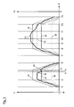
- Fig. 3 is on the axis X
- the travel time on the axis Y 1 is the actual rate of rotation and the upper turning rate limiting value, the lower turning rate limiting value and the expected turning rate, and plotted on the Y axis 2 of the steering angle
- the reference numeral 18 the course of the actual yaw rate
- the reference numeral 20 the course of the expected rate of turn
- the reference numerals 22 and 24 the course of the upper or lower rotation rate limit and the reference numeral 26 denotes the course of the steering angle. It is assumed that the motor vehicle moves over the entire time at a speed which is above the predetermined speed limit value.
- the motor vehicle drives without the driver performing a steering maneuver.
- the driver begins to turn on the steering wheel until it has reached the desired steering position at time t 3 .
- the expected rate of turn 20 of the motor vehicle also increases, the curve of the expected rate of rotation 20 always being surrounded by an envelope which is composed of the upper rate of rotation limit 22 and the lower rate of rotation limit 24.
- the motor vehicle understeers - for example by the deflected wheels slip on the road - so strong that the actual rate of rotation 18 is smaller than the lower rotation rate limit 24.
- the duration between the times t 3 and t 4 is less than the predetermined period of time, so that the belt tensioner 4 is not activated.
- the driver returns the steering wheel from the deflected position back to the original position and moves until time t 7 only straight ahead without hitting the steering wheel.
- the driver performs the same steering movement as between the times t 1 and t 6 .
- This time however, it comes on the basis of the road condition o. ⁇ . But to the fact that the motor vehicle oversteers by the rear of the same breaks.
- the actual yaw rate 18 between the times t 9 and t 11 is greater than the upper yaw rate limit value 22.
- the predetermined time period in which the actual rate of rotation may be greater than the upper rotation rate limit, exceeded, ie at time t 10 of the belt tensioner 4 is activated.
Abstract
Description
Die vorliegende Erfindung betrifft ein Verfahren zur Steuerung eines reversiblen Gurtstraffers in einem Kraftfahrzeug. Die Erfindung betrifft ferner eine Sicherheitsanordnung für ein Kraftfahrzeug mit einem reversiblen Gurtstraffer.The present invention relates to a method for controlling a reversible belt tensioner in a motor vehicle. The invention further relates to a safety arrangement for a motor vehicle with a reversible belt tensioner.
Aus dem Stand der Technik sind unterschiedliche Sicherheitsanordnungen für Kraftfahrzeuge bekannt. Diese umfassen regelmäßig einen Aufwickelmechanismus zum automatischen Aufwickeln eines Sicherheitsgurtes um eine Gurtspule. Durch das automatische Aufwickeln wird erreicht, dass der angelegte Sicherheitsgurt locker und komfortabel an dem Körper des Fahrzeuginsassen anliegt und bei Nichtgebrauch des Sicherheitsgurtes um die Gurtspule aufgerollt ist. Das Abwickeln des Sicherheitsgurtes ist bei angelegtem Sicherheitsgurt leicht möglich, so dass die Bewegungsfreiheit des Fahrzeuginsassen gewährleistet ist.Different safety arrangements for motor vehicles are known from the prior art. These regularly include a winding mechanism for automatically winding a seat belt around a belt reel. By the automatic winding is achieved that the applied seat belt loosely and comfortably rests against the body of the vehicle occupant and is rolled up when not using the seat belt to the belt reel. The unwinding of the seat belt is easily possible when wearing a seat belt, so that the freedom of movement of the vehicle occupant is guaranteed.
Ferner sind bei den bekannten Sicherheitsanordnungen so genannte Gurtstraffer vorgesehen. Die Gurtstraffer bewirken eine Straffung des Sicherheitsgurtes, um den Fahrzeuginsassen gegen die Rückenlehne des Fahrzeugsitzes zu ziehen, so dass die Verletzungsgefahr im Falle eines Zusammenpralls des Fahrzeuges mit einem anderen Fahrzeug oder einem Verkehrshindernis verringert ist. Die bekannten Gurtstraffer können dabei in irreversible und reversible Gurtstraffer unterteilt werden. Der irreversible Gurtstraffer wird erst dann aktiviert, wenn es bereits zu einem Unfall, wie beispielsweise einem Zusammenprall mit einem anderen Fahrzeug gekommen ist. Crashsensoren ermitteln den Zusammenprall und entsenden ein entsprechendes Aktivierungssignal an den irreversiblen Gurtstraffer. Die irreversiblen Gurtstraffer können stets nur einmal aktiviert bzw. ausgelöst werden, da es ja definitiv zu einem Unfall gekommen ist. Die reversiblen Gurtstraffer sollen hingegen mehrmals, auch schnell hintereinander, auf Grund von Signalen ausgelöst werden können, die die Möglichkeit eines bevorstehenden Crashs andeuten. Das heißt, die reversiblen Gurtstraffer sollen immer dann aktiviert werden können, wenn ein Crash möglich oder wahrscheinlich ist, aber noch nicht stattgefunden hat bzw. festgestellt wurde.Furthermore, so-called belt tensioners are provided in the known safety arrangements. The belt tensioners cause a tightening of the seat belt to pull the vehicle occupant against the backrest of the vehicle seat, so that the risk of injury is reduced in the event of a collision of the vehicle with another vehicle or a traffic obstruction. The known belt tensioners can be divided into irreversible and reversible belt tensioners. The irreversible The belt tensioner is activated only when an accident has already occurred, such as a collision with another vehicle. Crash sensors detect the collision and send a corresponding activation signal to the irreversible belt tensioner. The irreversible belt tensioners can always be activated or triggered only once, since it has definitely come to an accident. The reversible belt tensioners, on the other hand, should be able to be triggered several times, even in quick succession, on the basis of signals that indicate the possibility of an imminent crash. That is, the reversible belt tensioners should be able to be activated whenever a crash is possible or probable, but has not yet occurred.
Eine kritische Fahrsituation wird bei den reversiblen Gurtstraffern nicht durch Crashsensoren, die lediglich den tatsächlich stattgefundenen Crash ermitteln, sondern durch Fahrdynamiksensoren ermittelt, die Informationen über den derzeitigen Bewegungszustand des Kraftfahrzeuges liefern. Hierzu gehört beispielsweise die Ermittlung der Längs-, Quer- und Vertikalbeschleunigung des Kraftfahrzeuges. Sollten diese gemessenen Werte einen Grenzwert überschreiten, so erfolgt die prophylaktische Aktivierung des reversiblen Gurtstraffers. Sollte der Grenzwert wieder unterschritten werden und tatsächlich kein Crash stattgefunden haben, so wird der reversible Gurtstraffer wieder deaktiviert, so dass der Sicherheitsgurt wieder in seine Normalstellung gebracht werden kann, in der dem Fahrzeuginsassen eine größere Bewegungsfreiheit eingeräumt ist. Bei der nächsten kritischen Fahrsituation ist es möglich, den reversiblen Gurtstraffer erneut zu aktivieren.In the reversible belt tensioners, a critical driving situation is not determined by crash sensors which merely determine the crash actually taking place, but rather by driving dynamics sensors which provide information about the current state of motion of the motor vehicle. This includes, for example, the determination of the longitudinal, lateral and vertical acceleration of the motor vehicle. If these measured values exceed a limit value, the prophylactic activation of the reversible belt tensioner takes place. If the limit falls below again and no crash has actually occurred, then the reversible belt tensioner is deactivated again, so that the seat belt can be brought back into its normal position, in which the vehicle occupant has a greater freedom of movement. At the next critical driving situation, it is possible to reactivate the reversible belt tensioner again.
Die
Die
Die
Die
- Erfassen der Geschwindigkeit und des Lenkwinkels des Kraftfahrzeuges,
- Berechnen einer erwarteten Drehrate des Kraftfahrzeuges um dessen Vertikalachse aus der Geschwindigkeit und dem Lenkwinkel, und
- Erfassen der tatsächlichen Drehrate des Kraftfahrzeuges um dessen Vertikalachse. D1 offenbart ebenfalls alle Merkmale des Oberbegriffs des
unabhängigen Anspruchs 8, nämlich eine Sicherheitsanordnung für ein Kraftfahrzeug mit einem Sicherheitsgurt, einem reversiblen Gurtstraffer, einer Erfassungseinrichtung zum Erfassen der Geschwindigkeit, des Lenkwinkels und der tatsächlichen Drehrate des Kraftfahrzeuges und einer Steuereinrichtung, mittels derer der Gurtstraffer aktivierbar und deaktivierbar ist.
- Detecting the speed and the steering angle of the motor vehicle,
- Calculating an expected rate of turn of the motor vehicle about its vertical axis from the speed and the steering angle, and
- Detecting the actual rate of rotation of the motor vehicle about its vertical axis. D1 also discloses all features of the preamble of
independent claim 8, namely a safety arrangement for a motor vehicle with a safety belt, a reversible belt tensioner, a detection device for detecting the speed, the steering angle and the actual rate of rotation of the motor vehicle and a control device by means of which the belt tensioner activatable and can be deactivated.
Die bekannten Verfahren zur Steuerung eines reversiblen Gurtstraffers haben sich bewährt, jedoch findet keine geeignete Ansteuerung des Gurtstraffers bei gefährlichen Lenkmanövern statt, so dass die Sicherheit des Fahrzeuginsassen bei gefährlichen Lenkmanövern verbesserungswürdig ist.The known methods for controlling a reversible belt tensioner have been proven, but finds no suitable control of the belt tensioner in dangerous steering maneuvers instead, so that the safety of the vehicle occupant in dangerous steering maneuvers is in need of improvement.
Es ist daher eine Aufgabe der vorliegenden Erfindung, ein Verfahren zur Steuerung eines reversiblen Gurtstraffers in einem Kraftfahrzeug anzugeben, das eine geeignete Ansteuerung des Gurtstraffers bei gefährlichen Lenkmanövern ermöglicht, so dass die Sicherheit des Fahrzeuginsassen erhöht ist. Der Erfindung liegt ferner die Aufgabe zu Grunde, eine Sicherheitsanordnung mit einem reversiblen Gurtstraffer zu schaffen, mit der das erfindungsgemäße Verfahren ausführbar ist.It is therefore an object of the present invention to provide a method for controlling a reversible belt tensioner in a motor vehicle, which allows a suitable control of the belt tensioner in dangerous steering maneuvers, so that the safety of the vehicle occupant is increased. The invention is further based on the object to provide a safety arrangement with a reversible belt tensioner with which the inventive method is executable.
Diese Aufgabe wird durch die in den Patentansprüchen 1 bzw. 8 angegebenen Merkmale gelöst. Vorteilhafte Ausführungsformen der Erfindung sind Gegenstand der Unteransprüche.This object is achieved by the features specified in the
Das erfindungsgemäße Verfahren zur Steuerung eines reversiblen Gurtstraffers in einem Kraftfahrzeug weist die folgenden Verfahrensschritte auf. Zunächst wird die Geschwindigkeit des Kraftfahrzeuges sowie und der Lenkwinkel des Kraftfahrzeuges erfasst. Anschließend wird an Hand der erfassten Geschwindigkeit und des Lenkwinkels eine erwartete Drehrate des Kraftfahrzeuges um dessen Vertikalachse berechnet. Hierbei kann beispielsweise von dem Idealfall ausgegangen werden, bei dem der Lenkwinkel exakt in den gewünschten Kurvenverlauf umgesetzt wird, ohne dass es zu einem Über- oder Untersteuern kommt. die erwartete Drehrate kann beispielsweise die Winkelgeschwindigkeit bezogen auf eine Drehung um die Vertikalachse sein. Anschließend wird an Hand der berechneten erwarteten Drehrate ein oberer und unterer Drehratengrenzwert berechnet. Dies kann beispielsweise mit Hilfe eines Toleranzfaktors für den oberen bzw. den unteren Drehratengrenzwert erfolgen. Danach wird die tatsächliche Drehrate des Kraftfahrzeuges um dessen Vertikalachse erfasst. Nun erfolgt ein Vergleich zwischen der tatsächlichen Drehrate und dem oberen bzw. unteren Drehratengrenzwert. Ist die tatsächliche Drehrate des Kraftfahrzeuges größer als der obere Drehratengrenzwert oder kleiner als der untere Drehratengrenzwert, so wird der Gurtstraffer aktiviert.The method according to the invention for controlling a reversible belt tensioner in a motor vehicle has the following method steps. First, the speed of the motor vehicle and the steering angle of the motor vehicle is detected. Subsequently, an expected rate of rotation of the motor vehicle about its vertical axis is calculated on the basis of the detected speed and the steering angle. In this case, for example, it can be assumed that the ideal case in which the steering angle is converted exactly into the desired curve, without causing oversteer or understeer. the expected rate of rotation may be, for example, the angular velocity with respect to a rotation about the vertical axis. Subsequently, an upper and lower rotation rate limit value is calculated on the basis of the calculated expected rotation rate. This can be done, for example, with the help of a tolerance factor for the upper or the lower rotation rate limit. Thereafter, the actual rate of rotation of the motor vehicle is detected around its vertical axis. Now, a comparison is made between the actual yaw rate and the upper or lower yaw rate limit. If the actual turning rate of the motor vehicle is greater than the upper turning rate limit or Less than the lower rate of turn rate, the belt tensioner is activated.
Das erfindungsgemäße Verfahren führt zu einem situationsgerechten Ansteuern des Gurtstraffers bei gefährlichen Lenkmanövern. So wird ein Über- oder Untersteuern des Kraftfahrzeuges durch Überschreiten bzw. Unterschreiten des oberen bzw. unteren Drehratengrenzwertes sicher erfasst, und führt zur Aktivierung des Gurtstraffers.The method according to the invention leads to a situation-appropriate control of the belt tensioner in dangerous steering maneuvers. Thus, an oversteer or understeer of the motor vehicle is reliably detected by exceeding or falling below the upper or lower rotation rate limit, and leads to the activation of the belt tensioner.
In einer bevorzugten Ausführungsform des erfindungsgemäßen Verfahrens erfolgt das Aktivieren des Gurtstraffers ferner erst dann, wenn die tatsächliche Drehrate des Kraftfahrzeuges für eine vorbestimmte Zeitdauer größer bzw. kleiner als der obere bzw. untere Drehratengrenzwert ist. Auf diese Weise ist sichergestellt, dass die Straffung des Sicherheitsgurtes erst bei einem tatsächlich gefährlichen Lenkmanöver erfolgt. Ein solches gefährliches Lenkmanöver liegt nämlich bei einem nur kurzzeitigen Über- bzw. Unterschreiten der Drehratengrenzwerte in der Regel nicht vor.In a preferred embodiment of the method according to the invention, the activation of the belt tensioner is further only when the actual rate of rotation of the motor vehicle for a predetermined period of time is greater or less than the upper or lower rotation rate limit. In this way, it is ensured that the tightening of the seat belt takes place only in an actually dangerous steering maneuver. Such a dangerous steering maneuver is usually not present if the turning rate limit values are only briefly exceeded or fallen short of.
In einer vorteilhaften Ausführungsform des erfindungsgemäßen Verfahrens wird die vorbestimmte Zeitdauer in Abhängigkeit von der Geschwindigkeit des Kraftfahrzeuges festgelegt. Durch diese Maßnahme kann eine weitere Vorauswahl vorgenommen werden, ob tatsächlich ein gefährliches Lenkmanöver vorliegt.In an advantageous embodiment of the method according to the invention, the predetermined period of time is determined as a function of the speed of the motor vehicle. By this measure, a further preselection can be made as to whether there is actually a dangerous steering maneuver.
In einer besonders vorteilhaften Ausführungsform des erfindungsgemäßen Verfahrens ist die vorbestimmte Zeitdauer geringer, je höher die Geschwindigkeit des Kraftfahrzeuges ist. Hierdurch wird der Tatsache Rechnung getragen, dass ein kurzzeitiges Über- oder Untersteuern bei einer hohen Geschwindigkeit des Kraftfahrzeuges gefährlicher ist als ein kurzzeitiges Über- oder Untersteuern bei einer geringen Geschwindigkeit. Die vorbestimmte Zeitdauer kann bei steigender Geschwindigkeit beispielsweise linear oder stufenweise absinken.In a particularly advantageous embodiment of the method according to the invention, the predetermined time duration is lower, the higher the speed of the motor vehicle. In this way, the fact is taken into account that a short-term oversteer or understeer at a high speed of the motor vehicle is more dangerous than a short-term oversteer or understeer at a low speed. The predetermined period of time may, for example, decrease linearly or stepwise as the speed increases.
Da ein Über- oder Untersteuern bei niedrigen Geschwindigkeiten des Kraftfahrzeuges regelmäßig keine gefährliche Situation darstellt, erfolgt in einer besonders bevorzugten Ausführungsform des erfindungsgemäßen Verfahrens das Aktivieren des Gurtstraffers ferner erst dann, wenn die Geschwindigkeit des Kraftfahrzeuges höher als ein vorbestimmter Geschwindigkeitsgrenzwert ist. Dieser könnte beispielsweise bei 40 km/h festgelegt werden.Since an oversteer or understeer at low speeds of the motor vehicle is usually not a dangerous situation, in a particularly preferred embodiment of the method according to the invention, the activation of the belt tensioner further only when the speed of the motor vehicle is higher than a predetermined speed limit. This could for example be set at 40 km / h.
In einer besonders bevorzugten Ausführungsform des erfindungsgemäßen Verfahrens wird der obere bzw. untere Drehratengrenzwert durch Multiplikation der erwarteten Drehrate mit einem ersten bzw. zweiten Toleranzfaktor berechnet, wobei der erste Toleranzfaktor größer und der zweite Toleranzfaktor kleiner als 1 ist. So könnte der erste Toleranzfaktor beispielsweise 1,6 betragen, während der zweite Toleranzfaktor beispielsweise mit 0,75 festgelegt ist.In a particularly preferred embodiment of the method according to the invention, the upper or lower rotation rate limit value is calculated by multiplying the expected rotation rate by a first or second tolerance factor, wherein the first tolerance factor is greater and the second tolerance factor is less than one. For example, the first tolerance factor could be 1.6 while the second tolerance factor is set at 0.75, for example.
In einer vorteilhaften Ausführungsform des erfindungsgemäßen Verfahrens ist der weitere Verfahrensschritt des Deaktivierens des aktivierten Gurtstraffers vorgesehen, wenn die tatsächliche Drehrate des Kraftfahrzeuges wieder kleiner als der obere Drehratengrenzwert und größer als der untere Drehratengrenzwert ist.In an advantageous embodiment of the method according to the invention, the further method step of deactivating the activated belt tensioner is provided when the actual turning rate of the motor vehicle is again smaller than the upper turning rate limit value and greater than the lower turning rate limit value.
Nachfolgend wird die erfindungsgemäße Sicherheitsanordnung beschrieben, wobei bezüglich der hiermit erzielten Vorteile auf die oben stehende Beschreibung des erfindungsgemäßen Verfahrens verwiesen sein soll.The safety arrangement according to the invention is described below, reference being made to the above description of the method according to the invention with regard to the advantages achieved thereby.
Die erfindungsgemäße Sicherheitsanordnung für ein Kraftfahrzeug weist einen Sicherheitsgurt, einen reversiblen Gurtstraffer, eine Erfassungseinrichtung zum Erfassen der Geschwindigkeit, des Lenkwinkels und der tatsächlichen Drehrate des Kraftfahrzeuges und eine Steuereinrichtung auf, mittels derer der Gurtstraffer aktivierbar und deaktivierbar ist. Unter dem Aktivieren bzw. Deaktivieren des Gurtstraffers ist das Auslösen bzw. das Rückgängigmachen der Auslösung zu verstehen. Es ist ferner eine Berechnungseinrichtung vorgesehen, mittels derer eine erwartete Drehrate des Kraftfahrzeuges um dessen Vertikalachse aus der Geschwindigkeit und dem Lenkwinkel und ein oberer und unterer Drehratengrenzwert an Hand der erwarteten Drehrate berechnet werden kann. Die Steuereinrichtung wirkt derart mit dem Gurtstraffer zusammen, dass der Gurtstraffer aktiviert wird, wenn die tatsächliche Drehrate des Kraftfahrzeuges größer als der obere Drehratengrenzwert oder kleiner als der untere Drehratengrenzwert ist.The safety arrangement according to the invention for a motor vehicle has a safety belt, a reversible belt tensioner, a detection device for detecting the speed, the steering angle and the actual rate of rotation of the motor vehicle and a control device by means of which the belt tensioner can be activated and deactivated. Under activating or deactivating the belt tensioner is to be understood as triggering or reversing the release. A calculation device is furthermore provided, by means of which an expected rate of rotation of the motor vehicle about its vertical axis from the speed and the steering angle and an upper and lower rotation rate limit can be calculated on the basis of the expected rate of rotation. The control device interacts with the belt tensioner in such a way that the belt tensioner is activated when the actual rate of turn of the motor vehicle is greater than the upper turning rate limit value or less than the lower turning rate limit value.
In einer bevorzugten Ausführungsform der erfindungsgemäßen Sicherheitsanordnung wirkt die Steuereinrichtung derart mit dem Gurtstraffer zusammen, dass der Gurtstraffer ferner nur dann aktiviert wird, wenn die tatsächliche Drehrate des Kraftfahrzeuges für eine vorbestimmte Zeitdauer größer bzw. kleiner als der obere bzw. untere Drehratengrenzwert ist.In a preferred embodiment of the safety arrangement according to the invention, the control device cooperates with the belt tensioner such that the belt tensioner is further activated only if the actual rate of rotation of the motor vehicle for a predetermined period of time is greater or less than the upper or lower rotation rate limit.
In einer weiteren bevorzugten Ausführungsform der erfindungsgemäßen Sicherheitsanordnung kann die vorbestimmte Zeitdauer in Abhängigkeit von der Geschwindigkeit des Kraftfahrzeuges verändert werden.In a further preferred embodiment of the safety arrangement according to the invention, the predetermined period of time can be changed as a function of the speed of the motor vehicle.
In einer vorteilhaften Ausführungsform der erfindungsgemäßen Sicherheitsanordnung kann die vorbestimmte Zeitdauer durch Erhöhen der Geschwindigkeit des Kraftfahrzeuges verringert werden.In an advantageous embodiment of the safety arrangement according to the invention, the predetermined time duration can be reduced by increasing the speed of the motor vehicle.
In einer weiteren vorteilhaften Ausführungsform der erfindungsgemäßen Sicherheitsanordnung wirkt die Steuereinrichtung derart mit dem Gurtstraffer zusammen, dass der Gurtstraffer ferner nur dann aktiviert wird, wenn die Geschwindigkeit des Kraftfahrzeuges höher als ein vorbestimmter Geschwindigkeitsgrenzwert ist.In a further advantageous embodiment of the safety arrangement according to the invention, the control device cooperates with the belt tensioner such that the belt tensioner is further activated only when the speed of the motor vehicle is higher than a predetermined speed limit.
In einer bevorzugten Ausführungsform der erfindungsgemäßen Sicherheitsanordnung wird mit Hilfe der Berechnungseinrichtung der obere bzw. untere Drehratengrenzwert durch Multiplikation der erwarteten Drehrate mit einem ersten bzw. zweiten Toleranzfaktor berechnet, wobei der erste Toleranzfaktor größer und der zweite Toleranzfaktor kleiner als 1 ist.In a preferred embodiment of the safety arrangement according to the invention, the upper or lower rotation rate limit value is calculated by multiplying the expected rotation rate by a first or second tolerance factor with the aid of the calculation device, wherein the first tolerance factor is greater and the second tolerance factor is less than one.
In einer weiteren vorteilhaften Ausführungsform der erfindungsgemäßen Sicherheitsanordnung kann der aktivierte Gurtstraffer deaktiviert werden, wenn die tatsächliche Drehrate des Kraftfahrzeuges wieder kleiner als der obere Drehratengrenzwert und größer als der untere Drehratengrenzwert ist.In a further advantageous embodiment of the safety arrangement according to the invention, the activated seat belt pretensioner can be deactivated when the actual rate of turn of the motor vehicle is again smaller than the upper turning rate limit value and greater than the lower turning rate limit value.
Die Erfindung wird im Folgenden an Hand von beispielhaften Ausführungsformen unter Bezugnahme auf die zugehörigen Zeichnungen näher erläutert. Es zeigen:
- Fig. 1
- eine schematische Darstellung einer Ausfüh- rungsform der erfindungsgemäßen Sicher- heitsanordnung,
- Fig. 2
- ein Ablaufdiagramm zur Erläuterung einer Ausführungsform des erfindungsgemäßen Verfahrens und
- Fig. 3
- ein Diagramm zur Erläuterung des erfin- dungsgemäßen Verfahrens in bestimmten Fahr- situationen.
- Fig. 1
- 1 a schematic representation of an embodiment of the safety arrangement according to the invention,
- Fig. 2
- a flowchart for explaining an embodiment of the method according to the invention and
- Fig. 3
- a diagram for explaining the inventive method in certain driving situations.
Die Sicherheitsanordnung 2 weist ferner eine Erfassungseinrichtung 8 zum Erfassen der Geschwindigkeit, des Lenkwinkels und der tatsächlichen Drehrate des Kraftfahrzeuges auf. Zu diesem Zweck steht die Erfassungseinrichtung 8 mit einem Geschwindigkeitssensor 10 zur Erfassung der Geschwindigkeit des Kraftfahrzeuges, einem Lenkwinkelsensor 12 zur Erfassung des Lenkwinkels des Kraftfahrzeuges und einem Drehratensensor 14 zur Erfassung der tatsächlichen Drehrate des Kraftfahrzeuges in Verbindung. Als Geschwindigkeitssensor 10 kann der ohnehin im Kraftfahrzeug vorhandene Geschwindigkeitssensor verwendet werden. Der Lenkwinkelsensor 12 kann beispielsweise die Stellung des Lenkrades oder die Stellung der Räder des Kraftfahrzeuges erfassen.The
Es ist ferner eine Berechnungseinrichtung 16 vorgesehen, der die erfassten Geschwindigkeiten, Lenkwinkel und tatsächlichen Drehraten zugeführt werden können. Die Berechnungseinrichtung 16 kann zum einen eine erwartete Drehrate des Kraftfahrzeuges unter Zugrundelegung des erfassten Lenkwinkels und der Geschwindigkeit des Kraftfahrzeuges berechnen. Zum anderen kann die Berechnungseinheit 16 an Hand der erwarteten Drehrate einen oberen und unteren Drehratengrenzwert berechnen. Hierbei verwendet die Berechnungseinrichtung 16 so genannte Toleranzfaktoren.A
Die somit erfassten und berechneten Daten können an die Steuereinrichtung 6 übermittelt werden, wo eine Auswertung der Daten stattfindet. Der Gurtstraffer 4 wird erst dann durch die Steuereinrichtung 6 aktiviert, wenn die Geschwindigkeit des Kraftfahrzeuges höher als ein vorbestimmter Geschwindigkeitsgrenzwert ist, die tatsächliche Drehrate des Kraftfahrzeuges größer als der obere Drehratengrenzwert oder kleiner als der untere Drehratengrenzwert ist und die tatsächliche Drehrate des Kraftfahrzeuges für eine vorbestimmte Zeitdauer größer bzw. kleiner als der obere bzw. untere Drehratengrenzwert ist. Die vorbestimmte Zeitdauer ist dabei umso geringer, je größer die Geschwindigkeit des Kraftfahrzeuges ist.The thus acquired and calculated data can be transmitted to the
Nachstehend wird das der zuvor beschriebenen Sicherheitsanordnung 2 zu Grunde liegende erfindungsgemäße Verfahren unter Bezugnahme auf
In einem ersten Verfahrensschritt S1 erfasst die Erfassungseinrichtung 8 über den Geschwindigkeitssensor 10 und den Lenkwinkelsensor 12 die Geschwindigkeit und den Lenkwinkel des Kraftfahrzeuges.In a first method step S1, the
In einem nachfolgenden Verfahrensschritt S2 berechnet die Berechnungseinrichtung 16 die erwartete Drehrate des Kraftfahrzeuges um dessen Vertikalachse. Dies ist einfach auf Grundlage des erfassten Lenkwinkels sowie der erfassten Geschwindigkeit des Kraftfahrzeuges möglich. Bei der Berechnung der erwarteten Drehrate wird demzufolge vom Idealfall ausgegangen, nämlich dass das Kraftfahrzeug der gewünschten Lenkrichtung folgt, ohne über- oder untersteuert zu werden. An Hand der errechneten erwarteten Drehrate wird nun ein oberer und unterer Drehratengrenzwert ermittelt. Der obere Drehratengrenzwert wird durch Multiplikation der erwarteten Drehrate mit einem ersten Toleranzfaktor in Höhe von 1, 6 und der untere Drehratengrenzwert wird durch Multiplikation der erwarteten Drehrate mit einem zweiten Toleranzfaktor in Höhe von 0,75 errechnet. Auf diese Weise entsteht über die Zeit eine Hüllkurve um die erwartete Drehrate, auf die später in
In einem nächsten Verfahrensschritt S3 erfasst die, Erfassungseinrichtung 8 über den Drehratensensor 14 die tatsächliche Drehrate des Kraftfahrzeuges. Es sei erwähnt, dass sowohl die tatsächliche Drehrate als auch der Lenkwinkel und die Geschwindigkeit des Kraftfahrzeuges kontinuierlich erfasst werden, um aus diesen die entsprechenden o. g. Werte zu berechnen.In a next method step S3, the
Im Verfahrensschritt S4 wird eine Abfrage durchgeführt, ob die erfasste Geschwindigkeit des Kraftfahrzeuges höher als ein vorbestimmter Geschwindigkeitsgrenzwert ist, der im vorliegenden Beispiel bei 40 km/h festgelegt wurde. Ist dies nicht der Fall, so wird wieder mit Schritt S1 begonnen. Liegt die erfasste Geschwindigkeit jedoch oberhalb des Geschwindigkeitsgrenzwertes, so wird mit dem Verfahrensschritt S5 fortgefahren.In method step S4, a query is carried out as to whether the detected speed of the motor vehicle is higher is a predetermined speed limit set at 40 km / h in the present example. If this is not the case, step S1 is started again. However, if the detected speed is above the speed limit, then the method step S5 is continued.
Im Verfahrensschritt S5 wird nun die Abfrage durchgeführt, ob die tatsächliche Drehrate des Kraftfahrzeuges größer als der obere Drehratengrenzwert oder kleiner als der untere Drehratengrenzwert ist. Sollte dies nicht der Fall sein, so beginnt die Prozedur wieder bei dem Verfahrensschritt S1. Anderenfalls wird mit dem Verfahrensschritt S6 fortgefahren.In method step S5, the query is then carried out as to whether the actual rate of rotation of the motor vehicle is greater than the upper rotation rate limit value or less than the lower rotation rate limit value. If this is not the case, then the procedure starts again in method step S1. Otherwise, the method step S6 is continued.
Im Verfahrensschritt S6 wird erneut eine Abfrage durchgeführt, und zwar wird geprüft, ob die tatsächliche Drehrate des Kraftfahrzeuges bereits für eine vorbestimmte Zeitdauer größer bzw. kleiner als der obere bzw. untere Drehratengrenzwert ist. Sollte dies nicht der Fall sein, so werden zunächst die Schritte S1 bis S5 wiederholt, um anschließend - nachdem wieder Zeit verstrichen ist - erneut in Schritt S6 zu prüfen, ob die vorbestimmte Zeitdauer mittlerweile überschritten ist. Sollte die vorbestimmte Zeitdauer erreicht bzw. überschritten sein so wird mit dem Verfahrensschritt S7 fortgefahren.In step S6, a query is again performed, namely, it is checked whether the actual rate of rotation of the motor vehicle for a predetermined period of time is greater or less than the upper or lower yaw rate limit. If this is not the case, steps S1 to S5 are first of all repeated in order subsequently to check again, after time has elapsed, again in step S6, as to whether the predetermined period of time has meanwhile been exceeded. If the predetermined time period has been reached or exceeded, the method step S7 is continued.
Im Verfahrensschritt S7 ergeht von der Steuereinrichtung 6 ein entsprechendes Signal an den Gurtstraffer 4, der daraufhin aktiviert wird, so dass der Sicherheitsgurt gestrafft wird. Im Verfahrensschritt S8 wird geprüft, ob die tatsächliche Drehrate des Kraftfahrzeuges wieder kleiner als der obere Drehratengrenzwert und größer als der untere Drehratengrenzwert geworden ist. Sollte dies nicht der Fall sein, so bleibt der Gurtstraffer 4 aktiviert, anderenfalls erfolgt die Deaktivierung des Gurtstraffers im Verfahrensschritt S9, bevor die Prozedur erneut bei dem Verfahrensschritt S1 beginnt.In method step S7, the
Nachfolgend wird die Funktionsweise der in
In
In dem Zeitraum t0 bis t1 fährt das Kraftfahrzeug, ohne dass der Fahrer ein Lenkmanöver durchführt. Im Zeitpunkt t2 beginnt der Fahrer an dem Lenkrad zu drehen, bis dieses die gewünschte Lenkstellung zum Zeitpunkt t3 erreicht hat. Wie aus
Zwischen den Zeitpunkten t7 und t13 führt der Fahrer die gleiche Lenkbewegung durch wie zwischen den Zeitpunkten t1 und t6. Diesmal kommt es auf Grund der Fahrbahnbeschaffenheit o. ä. jedoch dazu, dass das Kraftfahrzeug übersteuert, indem das Heck desselben ausbricht. Dies führt dazu, dass die tatsächliche Drehrate 18 zwischen den Zeitpunkten t9 und t11 größer als der obere Drehratengrenzwert 22 ist. Zum Zeitpunkt t10 wird die vorbestimmte Zeitdauer, in der die tatsächliche Drehrate größer als der obere Drehratengrenzwert sein darf, überschritten, d.h. zum Zeitpunkt t10 wird der Gurtstraffer 4 aktiviert.Between the times t 7 and t 13 , the driver performs the same steering movement as between the times t 1 and t 6 . This time, however, it comes on the basis of the road condition o. Ä. But to the fact that the motor vehicle oversteers by the rear of the same breaks. As a result, the
Wenn die tatsächliche Drehrate 18 wieder kleiner als der obere Drehratengrenzwert 22 ist, wie hier zum Zeitpunkt t11, wird der Gurtstraffer wieder deaktiviert.If the
- 22
- Sicherheitsanordnungsecurity arrangement
- 44
- Gurtstrafferpretensioners
- 66
- Steuereinrichtungcontrol device
- 88th
- Erfassungseinrichtungdetector
- 1010
- Geschwindigkeitssensorspeed sensor
- 1212
- LenkwinkelsensorSteering angle sensor
- 1414
- DrehratensensorYaw rate sensor
- 1616
- Berechnungseinrichtungcalculator
- 1818
- tatsächliche Drehrateactual rate of rotation
- 2020
- erwartete Drehrateexpected rate of turn
- 2222
- oberer Drehratengrenzwertupper rotation rate limit
- 2424
- unterer Drehratengrenzwertlower yaw rate limit
- 2626
- Lenkwinkelsteering angle
- t1 - t13 t 1 - t 13
- Zeitpunktetimings
Claims (14)
- A method for controlling a reversible seat belt pretensioner in a motor vehicle, comprising the following method steps:detecting the speed and the steering angle of the vehicle;calculating an expected turning rate of the vehicle about its vertical axis from the speed and the steering angle;calculating an upper and a lower turning rate limiting value using the expected turning rate;detecting the actual turning rate of the vehicle about its vertical axis;activating the seat belt pretensioner if the actual turning rate of the vehicle is greater than the upper turning rate limiting value or is less than the lower turning rate limiting value.
- A method according to claim 1, characterized in that the seat belt pretensioner is further only activated if the actual turning rate of the vehicle is greater than or less than the upper or lower turning rate limiting value for a predetermined period of time.
- A method according to claim 2, characterized in that the predetermined period of time is established as a function of the speed of the vehicle.
- A method according to claim 3, characterized in that the higher the vehicle speed, the shorter the predetermined period of time.
- A method according to one of the claims 1 to 4, characterized in that the seat belt pretensioner is only activated if the speed of the vehicle is higher than a predetermined speed limiting value.
- A method according to one of the preceding claims, characterized in that the upper or lower turning rate limiting value is calculated by multiplying the expected turning rate with a first or second tolerance factor, the first tolerance factor being greater than 1 and the second tolerance factor being less than 1.
- A method according to one of the preceding claims, with the further method step of deactivating the activated seat belt pretensioner when the actual turning rate of the vehicle is again less than the upper turning rate limiting value and greater than the lower turning rate limiting value.
- A safety arrangement for a motor vehicle, comprising a reversible seat belt pretensioner (4), a detection device (8) for detecting the speed, the steering angle (26) and the actual turning rate (18) of the vehicle, and a control device (6), by means of which it is possible to activate and deactivate the seat belt pretensioner (4), characterized in that a calculation device (16) is provided, by means of which it is possible to calculate an expected turning rate (20) of the motor vehicle about its vertical axis from the speed and the steering angle (26) and an upper and lower turning rate limiting value (22, 24) using the expected turning rate (20), wherein the control device (6) cooperates with the seat belt pretensioner (4) such that it is possible to activate the seat belt pretensioner (4) if the actual turning rate (18) of the motor vehicle is greater than the upper turning rate limiting value (22) or less than the lower turning rate limiting value (24).
- A safety arrangement according to claim 8, characterized in that it is further only possible to activate the seat belt pretensioner (4) if for a predetermined period of time the actual turning rate (18) of the vehicle is greater than, or less than, the upper or lower turning rate limiting value (22, 24).
- A safety arrangement according to claim 9, characterized in that the predetermined period of time can be varied as a function of the speed of the vehicle.
- A safety arrangement according to claim 10, characterized in that the predetermined period of time can be reduced by increasing the speed of the vehicle.
- A safety arrangement according to one of the claims 8 to 11, characterized in that it is further only possible to activate the seat belt pretensioner (4) when the speed of the motor vehicle is higher than a predetermined speed limiting value.
- A safety arrangement according to one of the claims 8 to 12, characterized in that the upper or lower turning rate limiting value (22, 24) can be calculated by multiplying the expected turning rate (20) with a first or second tolerance factor, the first tolerance factor being greater than 1 and the second tolerance factor being less than 1.
- A safety arrangement according to one of the claims 8 to 13, characterized in that it is possible to deactivate the activated seat belt pretensioner (4) when the actual turning rate (18) of the motor vehicle is again less than the upper turning rate limiting value (22) and greater than the lower turning rate limiting value (24).
Applications Claiming Priority (2)
| Application Number | Priority Date | Filing Date | Title |
|---|---|---|---|
| DE102005035862A DE102005035862A1 (en) | 2005-07-30 | 2005-07-30 | Reversible seat-belt-pretensioner controlling method for use in motor vehicle, involves activating seal-belt-pretensioner when actual rotational rate of vehicle is greater than upper threshold value or smaller than lower threshold value |
| PCT/EP2006/006748 WO2007014627A1 (en) | 2005-07-30 | 2006-07-11 | Method for controlling a belt pretensioner and safety arrangment comprising a belt pretensioner |
Publications (2)
| Publication Number | Publication Date |
|---|---|
| EP1912816A1 EP1912816A1 (en) | 2008-04-23 |
| EP1912816B1 true EP1912816B1 (en) | 2010-09-22 |
Family
ID=36997699
Family Applications (1)
| Application Number | Title | Priority Date | Filing Date |
|---|---|---|---|
| EP06776179A Not-in-force EP1912816B1 (en) | 2005-07-30 | 2006-07-11 | Method for controlling a belt pretensioner and safety arrangment comprising a belt pretensioner |
Country Status (8)
| Country | Link |
|---|---|
| US (1) | US8335614B2 (en) |
| EP (1) | EP1912816B1 (en) |
| JP (1) | JP2009502637A (en) |
| CN (1) | CN101233019B (en) |
| AT (1) | ATE482103T1 (en) |
| AU (1) | AU2006275180A1 (en) |
| DE (2) | DE102005035862A1 (en) |
| WO (1) | WO2007014627A1 (en) |
Families Citing this family (7)
| Publication number | Priority date | Publication date | Assignee | Title |
|---|---|---|---|---|
| DE102010015549B4 (en) * | 2010-04-20 | 2020-08-13 | Werner Bernzen | Method and device for controlling at least one reversible occupant protection device of a vehicle |
| DE102011106247B4 (en) * | 2011-07-01 | 2014-05-28 | Audi Ag | Method for controlling a reversible belt tensioner of a safety belt in a motor vehicle |
| CN103121434A (en) * | 2013-02-28 | 2013-05-29 | 安徽江淮汽车股份有限公司 | Safety belt tightening system and method |
| WO2017031435A1 (en) * | 2015-08-20 | 2017-02-23 | Takata Protection Systems, Inc. | Vehicular angle alert and safety system and method |
| KR102626248B1 (en) | 2017-12-11 | 2024-01-17 | 현대자동차주식회사 | An Active seat belt control apparatus and control method thereof |
| EP3636497B1 (en) | 2018-10-12 | 2021-05-19 | Toyota Jidosha Kabushiki Kaisha | Occupant restraint system for vehicle |
| JP7172941B2 (en) | 2019-10-07 | 2022-11-16 | トヨタ自動車株式会社 | vehicle occupant restraint system |
Family Cites Families (23)
| Publication number | Priority date | Publication date | Assignee | Title |
|---|---|---|---|---|
| DE19736328A1 (en) | 1997-08-21 | 1999-02-25 | Bayerische Motoren Werke Ag | Controlling accident protection triggering devices in motor vehicle |
| DE19811865A1 (en) * | 1998-03-18 | 1999-09-23 | Siemens Ag | Motor vehicle occupant protection device operation control method e.g. for airbag |
| DE19910596A1 (en) * | 1999-03-10 | 2000-09-14 | Volkswagen Ag | Method and arrangement for triggering restraint devices in a motor vehicle |
| DE19961799B4 (en) | 1999-12-21 | 2004-03-25 | Breed Automotive Technology, Inc., Lakeland | Passive safety system of a motor vehicle |
| DE10005010C2 (en) | 2000-02-04 | 2002-11-21 | Daimler Chrysler Ag | Method and safety restraint for restraining an occupant in a vehicle seat |
| DE10025260B4 (en) * | 2000-05-22 | 2004-11-25 | Conti Temic Microelectronic Gmbh | Method for the detection of rollover processes in motor vehicles with safety devices |
| DE10029061C2 (en) * | 2000-06-13 | 2003-12-11 | Breed Automotive Tech | Restraint |
| DE10057916C2 (en) * | 2000-11-21 | 2003-04-17 | Bosch Gmbh Robert | Control device for a restraint system in a motor vehicle |
| DE10065518B4 (en) | 2000-12-28 | 2004-10-14 | Robert Bosch Gmbh | Method for triggering restraint devices in a motor vehicle |
| DE10118062C2 (en) * | 2001-04-11 | 2003-08-07 | Bosch Gmbh Robert | Method for recognizing rollover processes in a motor vehicle |
| DE10121386C1 (en) | 2001-05-02 | 2002-08-29 | Daimler Chrysler Ag | Method for controlling a reversible occupant protection device in a motor vehicle |
| DE10230483A1 (en) | 2002-07-06 | 2004-01-15 | Robert Bosch Gmbh | Procedure for controlling a two-stage belt tensioner |
| DE10250732B3 (en) * | 2002-10-31 | 2004-04-08 | Daimlerchrysler Ag | Control device for driver and passenger protection in a motor vehicle, has a plausibility step to prevent unnecessary deployment decisions being carried out |
| KR100521169B1 (en) * | 2002-12-27 | 2005-10-12 | 현대자동차주식회사 | A method for controlling rollover of vehicle |
| DE10332024A1 (en) * | 2003-07-15 | 2005-02-17 | Daimlerchrysler Ag | Method for controlling a reversible belt tensioner in a motor vehicle |
| DE10333990A1 (en) * | 2003-07-25 | 2005-02-10 | Robert Bosch Gmbh | An occupant protection device for a vehicle and method for driving an occupant protection device for a vehicle for early detection of a critical driving situation |
| DE10337618B3 (en) * | 2003-08-16 | 2005-05-04 | Daimlerchrysler Ag | Control method for automobile passenger restraint system has evaluation criteria for monitored condition data adjusted in dependence on detection of use of telephone and/or reception of traffic announcement |
| DE10345726B4 (en) * | 2003-10-01 | 2013-11-14 | Robert Bosch Gmbh | A restraint system for restraining an occupant in a motor vehicle and method for dynamically controlling such a restraint system |
| US7403848B2 (en) * | 2004-08-16 | 2008-07-22 | Delphi Technologies, Inc. | Vehicle rollover detection method |
| DE102005035861B4 (en) | 2005-07-30 | 2014-07-31 | GM Global Technology Operations LLC (n. d. Ges. d. Staates Delaware) | Belt tightening system for a motor vehicle and safety system with such a belt tightening system |
| DE102005035849A1 (en) | 2005-07-30 | 2007-02-08 | GM Global Technology Operations, Inc., Detroit | Safety arrangement with a belt tensioner, motor vehicle with such a safety arrangement, and method for controlling a belt tensioner |
| DE102005035863A1 (en) | 2005-07-30 | 2007-02-01 | GM Global Technology Operations, Inc., Detroit | Method for controlling a belt tensioner and safety arrangement with a belt tensioner |
| DE102005035850A1 (en) | 2005-07-30 | 2007-02-01 | GM Global Technology Operations, Inc., Detroit | Safety arrangement`s reversible belt-tensioner controlling method for motor vehicle, involves activating reversible belt-tensioner, when gradients of measured values characterizing vehicle dynamics exceed predetermined threshold value |
-
2005
- 2005-07-30 DE DE102005035862A patent/DE102005035862A1/en not_active Withdrawn
-
2006
- 2006-07-11 AT AT06776179T patent/ATE482103T1/en active
- 2006-07-11 EP EP06776179A patent/EP1912816B1/en not_active Not-in-force
- 2006-07-11 US US11/996,717 patent/US8335614B2/en not_active Expired - Fee Related
- 2006-07-11 CN CN2006800283324A patent/CN101233019B/en not_active Expired - Fee Related
- 2006-07-11 AU AU2006275180A patent/AU2006275180A1/en not_active Abandoned
- 2006-07-11 WO PCT/EP2006/006748 patent/WO2007014627A1/en active Application Filing
- 2006-07-11 DE DE502006007927T patent/DE502006007927D1/en active Active
- 2006-07-11 JP JP2008524383A patent/JP2009502637A/en active Pending
Also Published As
| Publication number | Publication date |
|---|---|
| EP1912816A1 (en) | 2008-04-23 |
| ATE482103T1 (en) | 2010-10-15 |
| AU2006275180A1 (en) | 2007-02-08 |
| JP2009502637A (en) | 2009-01-29 |
| DE502006007927D1 (en) | 2010-11-04 |
| US20080300753A1 (en) | 2008-12-04 |
| DE102005035862A1 (en) | 2007-02-01 |
| US8335614B2 (en) | 2012-12-18 |
| CN101233019B (en) | 2010-05-19 |
| WO2007014627A1 (en) | 2007-02-08 |
| CN101233019A (en) | 2008-07-30 |
Similar Documents
| Publication | Publication Date | Title |
|---|---|---|
| EP1824707B1 (en) | Method and device for controlling an automatic emergency braking maneuver | |
| DE102004057604B4 (en) | Method for a safety system in a vehicle | |
| EP1122136B1 (en) | Safety device and method for restraining and occupant in a vehicle seat | |
| EP1574400B1 (en) | Method for actuating a reversible occupant protection system in a motor vehicle | |
| EP1720739B1 (en) | Device for determining a tendency to tilt | |
| EP1901941B1 (en) | Method and device for triggering a passenger protecting means | |
| DE102006051787B4 (en) | A method for controlling occupant protection means in a vehicle having a predictive environment detection unit | |
| EP1034985B9 (en) | Method and apparatus for controlling a passive restraint system of a vehicle | |
| EP1912816B1 (en) | Method for controlling a belt pretensioner and safety arrangment comprising a belt pretensioner | |
| EP2726329B1 (en) | Method for controlling a reversible belt tensioner of a safety belt in a motor vehicle | |
| WO2005100110A1 (en) | Method for controlling an occupant protection device in a vehicle and occupant protection system | |
| DE102005035850A1 (en) | Safety arrangement`s reversible belt-tensioner controlling method for motor vehicle, involves activating reversible belt-tensioner, when gradients of measured values characterizing vehicle dynamics exceed predetermined threshold value | |
| EP1599364B1 (en) | Method and device for determining the probability of an accident for a vehicle | |
| DE102010053352A1 (en) | Method for driving dynamics adaptation of passenger fixation, involves determining time point for activation corresponding to current vehicle data, and performing determination of curve beginning and curve progression | |
| EP1747943B1 (en) | Method for controlling a belt pretensioner and security arrangement with a pretensioner | |
| EP2900528B1 (en) | Method and device for operating a vehicle and vehicle having such a device | |
| EP1932735A2 (en) | Process and brake system for avoiding multiple-collision accidents and mitigating their effects | |
| WO2004106119A1 (en) | Safety system in a motor vehicle | |
| DE102006014008A1 (en) | Belt retractor`s active lock system controlling method, involves monitoring vehicle data e.g. vehicle speed, that is suitable for indicating critical driving situation, and effectuating locking of retractor if driving condition is detected | |
| EP2036778B1 (en) | Method for controlling irreversible retaining means according to the seat position of a person | |
| DE10337618B3 (en) | Control method for automobile passenger restraint system has evaluation criteria for monitored condition data adjusted in dependence on detection of use of telephone and/or reception of traffic announcement | |
| DE102008003079B4 (en) | Method and control device for controlling personal protective equipment for a vehicle | |
| DE102005039307A1 (en) | Method for deactivating safety measures e.g. warning flasher, for vehicle, relies on gathered vehicle-assigned variable e.g. angle of roll, steering angle, and deactivation and activation criteria | |
| DE102010023871A1 (en) | Occupant protection unit i.e. reversible belt tensioner, controlling method for car, involves identifying occupant, and enabling occupant protection unit with impending collision point and identified occupant | |
| WO2009043713A1 (en) | Method for reducing the consequences of an accident in motor vehicles |
Legal Events
| Date | Code | Title | Description |
|---|---|---|---|
| PUAI | Public reference made under article 153(3) epc to a published international application that has entered the european phase |
Free format text: ORIGINAL CODE: 0009012 |
|
| 17P | Request for examination filed |
Effective date: 20080229 |
|
| AK | Designated contracting states |
Kind code of ref document: A1 Designated state(s): AT BE BG CH CY CZ DE DK EE ES FI FR GB GR HU IE IS IT LI LT LU LV MC NL PL PT RO SE SI SK TR |
|
| GRAP | Despatch of communication of intention to grant a patent |
Free format text: ORIGINAL CODE: EPIDOSNIGR1 |
|
| GRAS | Grant fee paid |
Free format text: ORIGINAL CODE: EPIDOSNIGR3 |
|
| GRAA | (expected) grant |
Free format text: ORIGINAL CODE: 0009210 |
|
| AK | Designated contracting states |
Kind code of ref document: B1 Designated state(s): AT BE BG CH CY CZ DE DK EE ES FI FR GB GR HU IE IS IT LI LT LU LV MC NL PL PT RO SE SI SK TR |
|
| REG | Reference to a national code |
Ref country code: GB Ref legal event code: FG4D Free format text: NOT ENGLISH |
|
| REG | Reference to a national code |
Ref country code: CH Ref legal event code: EP |
|
| REG | Reference to a national code |
Ref country code: IE Ref legal event code: FG4D Free format text: LANGUAGE OF EP DOCUMENT: GERMAN |
|
| REF | Corresponds to: |
Ref document number: 502006007927 Country of ref document: DE Date of ref document: 20101104 Kind code of ref document: P |
|
| PG25 | Lapsed in a contracting state [announced via postgrant information from national office to epo] |
Ref country code: LT Free format text: LAPSE BECAUSE OF FAILURE TO SUBMIT A TRANSLATION OF THE DESCRIPTION OR TO PAY THE FEE WITHIN THE PRESCRIBED TIME-LIMIT Effective date: 20100922 Ref country code: FI Free format text: LAPSE BECAUSE OF FAILURE TO SUBMIT A TRANSLATION OF THE DESCRIPTION OR TO PAY THE FEE WITHIN THE PRESCRIBED TIME-LIMIT Effective date: 20100922 |
|
| REG | Reference to a national code |
Ref country code: NL Ref legal event code: VDEP Effective date: 20100922 |
|
| LTIE | Lt: invalidation of european patent or patent extension |
Effective date: 20100922 |
|
| PG25 | Lapsed in a contracting state [announced via postgrant information from national office to epo] |
Ref country code: PL Free format text: LAPSE BECAUSE OF FAILURE TO SUBMIT A TRANSLATION OF THE DESCRIPTION OR TO PAY THE FEE WITHIN THE PRESCRIBED TIME-LIMIT Effective date: 20100922 Ref country code: SI Free format text: LAPSE BECAUSE OF FAILURE TO SUBMIT A TRANSLATION OF THE DESCRIPTION OR TO PAY THE FEE WITHIN THE PRESCRIBED TIME-LIMIT Effective date: 20100922 |
|
| PG25 | Lapsed in a contracting state [announced via postgrant information from national office to epo] |
Ref country code: LV Free format text: LAPSE BECAUSE OF FAILURE TO SUBMIT A TRANSLATION OF THE DESCRIPTION OR TO PAY THE FEE WITHIN THE PRESCRIBED TIME-LIMIT Effective date: 20100922 Ref country code: SE Free format text: LAPSE BECAUSE OF FAILURE TO SUBMIT A TRANSLATION OF THE DESCRIPTION OR TO PAY THE FEE WITHIN THE PRESCRIBED TIME-LIMIT Effective date: 20100922 Ref country code: GR Free format text: LAPSE BECAUSE OF FAILURE TO SUBMIT A TRANSLATION OF THE DESCRIPTION OR TO PAY THE FEE WITHIN THE PRESCRIBED TIME-LIMIT Effective date: 20101223 |
|
| REG | Reference to a national code |
Ref country code: IE Ref legal event code: FD4D |
|
| PG25 | Lapsed in a contracting state [announced via postgrant information from national office to epo] |
Ref country code: IE Free format text: LAPSE BECAUSE OF FAILURE TO SUBMIT A TRANSLATION OF THE DESCRIPTION OR TO PAY THE FEE WITHIN THE PRESCRIBED TIME-LIMIT Effective date: 20100922 |
|
| REG | Reference to a national code |
Ref country code: DE Ref legal event code: R081 Ref document number: 502006007927 Country of ref document: DE Owner name: GM GLOBAL TECHNOLOGY OPERATIONS LLC (N. D. GES, US Free format text: FORMER OWNER: GM GLOBAL TECHNOLOGY OPERATIONS, INC., DETROIT, MICH., US Effective date: 20110323 |
|
| PG25 | Lapsed in a contracting state [announced via postgrant information from national office to epo] |
Ref country code: SK Free format text: LAPSE BECAUSE OF FAILURE TO SUBMIT A TRANSLATION OF THE DESCRIPTION OR TO PAY THE FEE WITHIN THE PRESCRIBED TIME-LIMIT Effective date: 20100922 Ref country code: PT Free format text: LAPSE BECAUSE OF FAILURE TO SUBMIT A TRANSLATION OF THE DESCRIPTION OR TO PAY THE FEE WITHIN THE PRESCRIBED TIME-LIMIT Effective date: 20110124 Ref country code: IT Free format text: LAPSE BECAUSE OF FAILURE TO SUBMIT A TRANSLATION OF THE DESCRIPTION OR TO PAY THE FEE WITHIN THE PRESCRIBED TIME-LIMIT Effective date: 20100922 Ref country code: IS Free format text: LAPSE BECAUSE OF FAILURE TO SUBMIT A TRANSLATION OF THE DESCRIPTION OR TO PAY THE FEE WITHIN THE PRESCRIBED TIME-LIMIT Effective date: 20110122 Ref country code: RO Free format text: LAPSE BECAUSE OF FAILURE TO SUBMIT A TRANSLATION OF THE DESCRIPTION OR TO PAY THE FEE WITHIN THE PRESCRIBED TIME-LIMIT Effective date: 20100922 Ref country code: CZ Free format text: LAPSE BECAUSE OF FAILURE TO SUBMIT A TRANSLATION OF THE DESCRIPTION OR TO PAY THE FEE WITHIN THE PRESCRIBED TIME-LIMIT Effective date: 20100922 Ref country code: EE Free format text: LAPSE BECAUSE OF FAILURE TO SUBMIT A TRANSLATION OF THE DESCRIPTION OR TO PAY THE FEE WITHIN THE PRESCRIBED TIME-LIMIT Effective date: 20100922 Ref country code: NL Free format text: LAPSE BECAUSE OF FAILURE TO SUBMIT A TRANSLATION OF THE DESCRIPTION OR TO PAY THE FEE WITHIN THE PRESCRIBED TIME-LIMIT Effective date: 20100922 |
|
| REG | Reference to a national code |
Ref country code: CH Ref legal event code: PFA Owner name: GM GLOBAL TECHNOLOGY OPERATIONS LLC Free format text: GM GLOBAL TECHNOLOGY OPERATIONS, INC.#300 RENAISSANCE CENTER#DETROIT, MI 48265-3000 (US) -TRANSFER TO- GM GLOBAL TECHNOLOGY OPERATIONS LLC#300 RENAISSANCE CENTER#DETROIT, MI 48265-3000 (US) |
|
| RAP2 | Party data changed (patent owner data changed or rights of a patent transferred) |
Owner name: GM GLOBAL TECHNOLOGY OPERATIONS LLC |
|
| PG25 | Lapsed in a contracting state [announced via postgrant information from national office to epo] |
Ref country code: ES Free format text: LAPSE BECAUSE OF FAILURE TO SUBMIT A TRANSLATION OF THE DESCRIPTION OR TO PAY THE FEE WITHIN THE PRESCRIBED TIME-LIMIT Effective date: 20110102 |
|
| PLBE | No opposition filed within time limit |
Free format text: ORIGINAL CODE: 0009261 |
|
| STAA | Information on the status of an ep patent application or granted ep patent |
Free format text: STATUS: NO OPPOSITION FILED WITHIN TIME LIMIT |
|
| 26N | No opposition filed |
Effective date: 20110623 |
|
| PG25 | Lapsed in a contracting state [announced via postgrant information from national office to epo] |
Ref country code: DK Free format text: LAPSE BECAUSE OF FAILURE TO SUBMIT A TRANSLATION OF THE DESCRIPTION OR TO PAY THE FEE WITHIN THE PRESCRIBED TIME-LIMIT Effective date: 20100922 |
|
| REG | Reference to a national code |
Ref country code: DE Ref legal event code: R097 Ref document number: 502006007927 Country of ref document: DE Effective date: 20110623 |
|
| BERE | Be: lapsed |
Owner name: GM GLOBAL TECHNOLOGY OPERATIONS, INC. Effective date: 20110731 |
|
| PG25 | Lapsed in a contracting state [announced via postgrant information from national office to epo] |
Ref country code: MC Free format text: LAPSE BECAUSE OF NON-PAYMENT OF DUE FEES Effective date: 20110731 |
|
| REG | Reference to a national code |
Ref country code: CH Ref legal event code: PL |
|
| PG25 | Lapsed in a contracting state [announced via postgrant information from national office to epo] |
Ref country code: BE Free format text: LAPSE BECAUSE OF NON-PAYMENT OF DUE FEES Effective date: 20110731 Ref country code: CH Free format text: LAPSE BECAUSE OF NON-PAYMENT OF DUE FEES Effective date: 20110731 Ref country code: LI Free format text: LAPSE BECAUSE OF NON-PAYMENT OF DUE FEES Effective date: 20110731 |
|
| REG | Reference to a national code |
Ref country code: AT Ref legal event code: MM01 Ref document number: 482103 Country of ref document: AT Kind code of ref document: T Effective date: 20110711 |
|
| PG25 | Lapsed in a contracting state [announced via postgrant information from national office to epo] |
Ref country code: AT Free format text: LAPSE BECAUSE OF NON-PAYMENT OF DUE FEES Effective date: 20110711 |
|
| PG25 | Lapsed in a contracting state [announced via postgrant information from national office to epo] |
Ref country code: CY Free format text: LAPSE BECAUSE OF EXPIRATION OF PROTECTION Effective date: 20100922 Ref country code: LU Free format text: LAPSE BECAUSE OF NON-PAYMENT OF DUE FEES Effective date: 20110711 |
|
| PG25 | Lapsed in a contracting state [announced via postgrant information from national office to epo] |
Ref country code: BG Free format text: LAPSE BECAUSE OF FAILURE TO SUBMIT A TRANSLATION OF THE DESCRIPTION OR TO PAY THE FEE WITHIN THE PRESCRIBED TIME-LIMIT Effective date: 20101222 Ref country code: TR Free format text: LAPSE BECAUSE OF FAILURE TO SUBMIT A TRANSLATION OF THE DESCRIPTION OR TO PAY THE FEE WITHIN THE PRESCRIBED TIME-LIMIT Effective date: 20100922 |
|
| PG25 | Lapsed in a contracting state [announced via postgrant information from national office to epo] |
Ref country code: HU Free format text: LAPSE BECAUSE OF FAILURE TO SUBMIT A TRANSLATION OF THE DESCRIPTION OR TO PAY THE FEE WITHIN THE PRESCRIBED TIME-LIMIT Effective date: 20100922 |
|
| PGFP | Annual fee paid to national office [announced via postgrant information from national office to epo] |
Ref country code: DE Payment date: 20140709 Year of fee payment: 9 |
|
| PGFP | Annual fee paid to national office [announced via postgrant information from national office to epo] |
Ref country code: FR Payment date: 20140708 Year of fee payment: 9 Ref country code: GB Payment date: 20140709 Year of fee payment: 9 |
|
| REG | Reference to a national code |
Ref country code: DE Ref legal event code: R119 Ref document number: 502006007927 Country of ref document: DE |
|
| GBPC | Gb: european patent ceased through non-payment of renewal fee |
Effective date: 20150711 |
|
| PG25 | Lapsed in a contracting state [announced via postgrant information from national office to epo] |
Ref country code: GB Free format text: LAPSE BECAUSE OF NON-PAYMENT OF DUE FEES Effective date: 20150711 Ref country code: DE Free format text: LAPSE BECAUSE OF NON-PAYMENT OF DUE FEES Effective date: 20160202 |
|
| REG | Reference to a national code |
Ref country code: FR Ref legal event code: ST Effective date: 20160331 |
|
| PG25 | Lapsed in a contracting state [announced via postgrant information from national office to epo] |
Ref country code: FR Free format text: LAPSE BECAUSE OF NON-PAYMENT OF DUE FEES Effective date: 20150731 |