EP1912235A1 - Actionnement par des contacts d'une chambre de coupure a double mouvement par un tube isolant - Google Patents
Actionnement par des contacts d'une chambre de coupure a double mouvement par un tube isolant Download PDFInfo
- Publication number
- EP1912235A1 EP1912235A1 EP07118007A EP07118007A EP1912235A1 EP 1912235 A1 EP1912235 A1 EP 1912235A1 EP 07118007 A EP07118007 A EP 07118007A EP 07118007 A EP07118007 A EP 07118007A EP 1912235 A1 EP1912235 A1 EP 1912235A1
- Authority
- EP
- European Patent Office
- Prior art keywords
- contact
- tube
- chamber according
- contacts
- axis
- Prior art date
- Legal status (The legal status is an assumption and is not a legal conclusion. Google has not performed a legal analysis and makes no representation as to the accuracy of the status listed.)
- Granted
Links
Images
Classifications
-
- H—ELECTRICITY
- H01—ELECTRIC ELEMENTS
- H01H—ELECTRIC SWITCHES; RELAYS; SELECTORS; EMERGENCY PROTECTIVE DEVICES
- H01H33/00—High-tension or heavy-current switches with arc-extinguishing or arc-preventing means
- H01H33/70—Switches with separate means for directing, obtaining, or increasing flow of arc-extinguishing fluid
- H01H33/88—Switches with separate means for directing, obtaining, or increasing flow of arc-extinguishing fluid the flow of arc-extinguishing fluid being produced or increased by movement of pistons or other pressure-producing parts
- H01H33/90—Switches with separate means for directing, obtaining, or increasing flow of arc-extinguishing fluid the flow of arc-extinguishing fluid being produced or increased by movement of pistons or other pressure-producing parts this movement being effected by or in conjunction with the contact-operating mechanism
- H01H33/904—Switches with separate means for directing, obtaining, or increasing flow of arc-extinguishing fluid the flow of arc-extinguishing fluid being produced or increased by movement of pistons or other pressure-producing parts this movement being effected by or in conjunction with the contact-operating mechanism characterised by the transmission between operating mechanism and piston or movable contact
-
- H—ELECTRICITY
- H01—ELECTRIC ELEMENTS
- H01H—ELECTRIC SWITCHES; RELAYS; SELECTORS; EMERGENCY PROTECTIVE DEVICES
- H01H33/00—High-tension or heavy-current switches with arc-extinguishing or arc-preventing means
- H01H33/02—Details
- H01H2033/028—Details the cooperating contacts being both actuated simultaneously in opposite directions
-
- H—ELECTRICITY
- H01—ELECTRIC ELEMENTS
- H01H—ELECTRIC SWITCHES; RELAYS; SELECTORS; EMERGENCY PROTECTIVE DEVICES
- H01H33/00—High-tension or heavy-current switches with arc-extinguishing or arc-preventing means
- H01H33/70—Switches with separate means for directing, obtaining, or increasing flow of arc-extinguishing fluid
- H01H33/88—Switches with separate means for directing, obtaining, or increasing flow of arc-extinguishing fluid the flow of arc-extinguishing fluid being produced or increased by movement of pistons or other pressure-producing parts
- H01H33/90—Switches with separate means for directing, obtaining, or increasing flow of arc-extinguishing fluid the flow of arc-extinguishing fluid being produced or increased by movement of pistons or other pressure-producing parts this movement being effected by or in conjunction with the contact-operating mechanism
- H01H33/905—Switches with separate means for directing, obtaining, or increasing flow of arc-extinguishing fluid the flow of arc-extinguishing fluid being produced or increased by movement of pistons or other pressure-producing parts this movement being effected by or in conjunction with the contact-operating mechanism the compression volume being formed by a movable cylinder and a semi-mobile piston
-
- H—ELECTRICITY
- H01—ELECTRIC ELEMENTS
- H01H—ELECTRIC SWITCHES; RELAYS; SELECTORS; EMERGENCY PROTECTIVE DEVICES
- H01H33/00—High-tension or heavy-current switches with arc-extinguishing or arc-preventing means
- H01H33/70—Switches with separate means for directing, obtaining, or increasing flow of arc-extinguishing fluid
- H01H33/88—Switches with separate means for directing, obtaining, or increasing flow of arc-extinguishing fluid the flow of arc-extinguishing fluid being produced or increased by movement of pistons or other pressure-producing parts
- H01H33/90—Switches with separate means for directing, obtaining, or increasing flow of arc-extinguishing fluid the flow of arc-extinguishing fluid being produced or increased by movement of pistons or other pressure-producing parts this movement being effected by or in conjunction with the contact-operating mechanism
- H01H33/91—Switches with separate means for directing, obtaining, or increasing flow of arc-extinguishing fluid the flow of arc-extinguishing fluid being produced or increased by movement of pistons or other pressure-producing parts this movement being effected by or in conjunction with the contact-operating mechanism the arc-extinguishing fluid being air or gas
Definitions
- the invention relates to high or medium voltage circuit breakers, whose operating energy is reduced by a double movement of the contacts.
- the invention relates to the actuation in opposite directions of the contacts of a circuit breaker interrupting chamber via an insulating tube surrounding the contacts, for example by means of a lever.
- the medium and high voltage switchgear apparatus comprises a pair of movable contacts relative to each other between a closed position in which the electric current can flow and an open position in which the electric current is interrupted.
- the speed of separation between the contacts is one of the main parameters to guarantee the dielectric strength of the circuit breaker when it is opened.
- a “main contact” is an electrical contact (with its corona shield) through which the nominal current flows; the term “movable contact” the main contact assembly and arc contact directly connected to the operating member.
- the opposite moving contact also composed of a main contact and an arc contact, is moved via a kinematic, which is itself connected to the moving contact.
- the document EP 0 822 565 discloses a circuit breaker for high and medium voltage in which a lever with two arms, one being connected to a nozzle secured to a first contact and the other to a second contact, allows the movement of the first contact simultaneously causes the second contact in the opposite direction.
- the return system can be made by a belt, or chain, closed around two gears: see document FR 2,774,503 .
- the invention proposes, among other advantages, to overcome the disadvantages described above, and both to achieve a system of double movement of the contacts and effectively protect the main contacts of the hot gases generated by the cut.
- an insulating tube is inserted into the breaking chamber around the main contacts.
- a volume of "clean" dielectric gas, SF 6 or CF 4 for example is maintained around these contacts during the tripping of the circuit breaker, which keeps good dielectric properties.
- the presence of the tube eliminates the reboots between main contacts, despite the compactness of the circuit breaker, which has for example a small insulator diameter.
- the insulating tube although having these two functions at least, still remains a very simple effort transmission system; it is made integral with a first movable contact, and it is it which causes, when triggering, the second contact (or opposite moving contact) for a displacement in the opposite direction via a connection to means of contact. actuation.
- the invention therefore relates to an interrupting chamber for a high or medium voltage circuit breaker comprising two movable contacts in translation in a direction opposite to each other, and surrounded by a tube. insulating material extending along the axis of translation.
- the movable contacts may each comprise a so-called main contact and an arcing contact; for example, the main contact and the arc contact of the second opposite movable contact can slide relative to each other.
- the insulating tube is fixed to a first contact, preferably to its main contact, and is connected to actuating means so that the tripping of the circuit breaker and the subsequent displacement of the contact drive the actuating means.
- the actuating means are also connected by connection means to the second contact, so that the displacement in one direction of the tube causes the displacement in the opposite direction of the second contact.
- the first contact is associated with a blowing nozzle, and the breaking chamber is filled with dielectric gas.
- the insulating tube is guided in translation, especially with respect to the main contacts, for example in a sealed manner, so that the hot gases can not be introduced between the contacts.
- a sealed guide between the blast nozzle and the main contact of the second opposite contact ensures a clean volume of dielectric gas around the main contacts. Cutoff performance can thus be improved.
- the insulating tube may be of different materials, including fiber arrangements in a resin.
- the tube material can also be loaded so that the tube can then additionally play a role of field distributor.
- the actuating means are in the form of one or more levers pivoting about an axis, advantageously secant and / or normal to the axis of displacement of the contacts.
- the connection means may be rigid rods or rods connected to the lever arms, and the dimensioning of the lever arms may be adjusted to optimize the speed ratio between the first and the second contact, or even between the main contact and the contact arc of the same moving contact.
- the invention in another aspect, relates to a high or medium voltage circuit breaker provided with a breaking chamber having an insulating tube which participates in actuating the contacts.
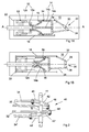
- FIGS. 1A and 1B schematically represent a double-movement interrupting chamber provided with the actuating device according to one embodiment of the invention, in the open and closed positions, respectively.
- Figure 2 illustrates actuating and connecting means forming part of a preferred embodiment of the invention.
- a high or medium voltage circuit breaker comprises a breaking chamber 10 which can be filled with an SF 6 type dielectric gas.
- the interrupting chamber 10 comprises a first movable contact 12, composed of an arc contact 12a and a main contact 12b, and a second contact (or opposite movable contact) 14, composed of an arc contact 14a. and a main contact 14b. These two elements cooperate between an open position ( Figure 1A) in which the two contacts 12, 14 are separated from one another and a closed position ( Figure 1B) in which they allow the passage of electric current between them.
- the two contacts 12, 14 move in opposite directions; the main contacts 12b, 14b separate, then the arcing contacts 12a, 14a separate, after a possible period of latency created by the length of the racking, forming an electric arc that goes out by the subsequent separation contacts 12, 14.
- the first contact 12 (even if, in the claims in particular, it could be the second contact 14) is usually secured to a nozzle 16 of insulating material, which itself extends a gas compression volume.
- This dielectric nozzle 16 serves as a nozzle for blowing the gas from the compression volume in the direction of the electric arc.
- the two main contacts 12b, 14b are located in an insulating tube 18, which surrounds them regardless of their open or closed position.
- this tube 18 is solid and its walls are uniform; the tube 18 may preferably be a hollow cylinder of revolution, but it may also be conical or even polygon
- the tube 18 may be a hollow cylinder made of thermoplastic or thermosetting polymer.
- thermoplastic polymers there may be mentioned in particular the families of unsaturated polyesters, or phenoplasts, or epoxy resins in reaction with anhydride hardeners of acids, or polybismaleides, or vinylester resins; among the thermoplastic polymers, there may be mentioned in particular families of thermoplastic polyesters, or polyamides, or polycarbonates, or polyphenylene oxides, or polysulfones, or polyphenylenesulfides, or polyetherketones, or liquid crystal polymers, or polyimides, or fluorinated polymers of PTFE type (polytetrafluoroethylene). An alloy of these materials can also be used.
- the tube 18 may also consist of a fiber arrangement, in particular mineral fibers such as glass fibers or polyester fibers or Kevlar TM type aramid fibers, each of which may be in the form of continuous yarns, long fibers (> 3 mm), short fibers ( ⁇ 3 mm), poles, or fabrics. It may alternatively or additionally contain, locally or in total, particulate reinforcements (alumina Al 2 O 3 , alumina trihydrate ATH, CaO calcium oxide, MgO magnesium oxide, SiO 2 silica, wollastonite, CaCO 3 calcium carbonate, TiO 2 titanium oxide, silicate compounds such as montmorillonites, vermiculites and kaolin), organic or inorganic.
- mineral fibers such as glass fibers or polyester fibers or Kevlar TM type aramid fibers, each of which may be in the form of continuous yarns, long fibers (> 3 mm), short fibers ( ⁇ 3 mm), poles, or fabrics. It may alternatively or additionally contain, locally or in total, particul
- the hollow cylinder 18 is made of filament windings, the angle given to the winding can be 0 ° to 90 ° evenly over the entire cylinder 18 or variable (this second case allows modify the mechanical properties of the cylinder locally).
- the fibers are impregnated, before or afterwards, with resin (under vacuum or not), for example an epoxy resin of bisphenol A, bisphenol F, or cycloaliphatic type.
- resin under vacuum or not
- Various reinforcing materials may also be used, such as mineral fibers such as glass fibers or polyester fibers or Kevlar TM type aramid fibers, each of which may be in the form of continuous yarns, long fibers (> 3 mm), short fibers ( ⁇ 3 mm), poles, or fabrics.
- a protective coating may be deposited, for instance on an approximately 30 .mu.m layer, such as an aliphatic polyurethane or a polyester film.
- the insulating roll 18 may be of variable geometry (local overthickness). It can also be manufactured with localized injections of fillers, on the surface or in the mass: indeed, in addition to its motion transmission and hot gas protection functions, the insulating cylinder 18 can also be used for an additional field distribution function.
- the cylinder 18 may comprise bisphenol A, bisphenol F or cycloaliphatic epoxy resins with localized injection of zinc oxide ZnO or TiO 2 titanium oxide type optimizing its electric field distribution function.
- another material may be overmolded on the inner and / or outer diameter of the cylinder 18, or deposited in a thin layer on its inner and / or outer diameter.
- the layer may be made of a polymer mixture (thermoplastic or thermosetting) with charge incorporation (material which can have a high relative permittivity) of ZnO, TiO 2 or carbon black type, the mass charge ratio being between 0, 1% and 300%, over a thickness of between 10 ⁇ m and 5 mm.
- the two contacts 12, 14 and the nozzle 16 move along the main axis AA of the breaking chamber 10 of the circuit breaker.
- the breaking chamber 10, the nozzle 16, the first and second contacts 12, 14, the insulating tube 18 are symmetrical about the axis AA.
- Each of the contacts 12, 14 is actuated in spacing or approximation by means of a single actuating system 20; in fact, the displacement of the movable contact 12 during the tripping of the circuit breaker causes the actuating system 20 which displaces the opposite mobile contact 14.
- the drive of the opposite moving contact 14 is done via the tube 18: this option allows a greater latitude of the actuating means 20 in view of the particularly complex geometry of the contact members of a high and medium voltage switchgear chamber; the insulating tube 18, by its diameter, allows to transmit a displacement in a wide range of maneuvering forces.
- the tube 18 can remain of reduced thickness: in fact, since it is a solid cylindrical tube, the charge is uniformly distributed, and the movement of the first movable contact 12 and the driving of the second opposite movable contact 14 do not occur. require no thick walls to be sufficiently resistant, for example the tube 18 may have walls of a few millimeters only to a few tens of millimeters.
- the insulating tube 18 is fixed to the contact 12, for example by a connecting pin, and preferably at its end 22 opposite to the actuating device 20. This makes it possible to release the other end for connection to the device 20, and optimizes the protection of the main contacts 12b, 14b by the "clean" dielectric gas.
- the connection between the insulating tube 18 and the connecting pin 22 on one side and the rod 32 on the other side can be achieved in several ways: by a simple hole in the cylinder 18 and / or via a metal collar fixed on the cylinder 18 at the end concerned, for example.
- the actuating means 20 may take various forms known to those skilled in the art.
- the actuating means 20 comprise a lever 24 with two arms 26, 28 pivoting about an axis 30.
- the first arm 26 is connected to the insulating tube 18 (and thus indirectly to the first contact 12). It therefore moves in the opposite direction of the second arm 28 connected to the second contact 14.
- the lever 24 is located on the side of the opposite contact 14, that is to say according to a lever command 24 - opposite moving contact 14 - nozzle 16 - moving contact 12 - end 22 of the tube 18.
- connection between the tube 18 and the first arm 26 is preferably made by a first rod 32 rigid; advantageously, the connection is provided by inserting a pivot at an end portion of the arm 26, and by a rotatable attachment on the end of the tube 18, for example by an axis.
- a rod or second rigid rod 34 pivotally connects an end portion of the second arm 28 and the contact 14.
- connection at the opposite contact 14 may be at greater or lesser distance from the axis AA of displacement.
- length of the arms 26, 28 of the lever 24 may be the same or different. According to one embodiment, the length of the two arms 26, 28 is maximum, that is to say of the order of the diameter of the insulating tube 18, in order to optimize the forces.
- connection rods 32, 34 connection can move a certain distance by sliding in a slot (not shown) of the second arm 28 before initiating its translational movement along the axis AA.
- the opposite contact 14 comprises an arc contact 14a and a main contact 14b
- these two elements 14a, 14b are slippery with respect to each other, and thus have strokes and strokes. different speeds.
- the arcing contact 14a and the main contact 14b are then connected to the actuating system 20 by a different link and lever (not shown).
- the axis 30 of the lever 24 is orthogonal to the axis AA of displacement, so that the end of the arms 26, 28 and therefore the connecting rods 32, 34 move in a plane movement allowing a less solicitation of their anchoring points.
- the axis 30 of the lever intersects the AA axis of displacement.
- the actuating means 40 comprise two levers 42, 42 'whose the pivot axes 44 are merged.
- the pivot axis 44 is normal to the axis AA of displacement and the section at a point B.
- the system 40 is axisymmetric: the two levers 42, 42 'are of identical shape and nature, and localized to the same distance from point B.
- each lever 42, 42' is connected by a first rod 32, 32 'to the tube 18, preferably at two diametrically opposite points.
- two second rods 34, 34 ' connect the second contact 14 and the two second arms 48, 48'.
- the arms of the levers 42, 42 ' are preferably non-aligned in the direction of the axis 44.
- the insulating tube 18 is guided in translation.
- a mechanical guiding system 52, 54 couples the tube 18 to at least one of the main contacts 12b, 14b.
- the guide 52, 54 is sealed: this prevents the hot gases generated from being introduced between the permanent contacts 12b, 14b.
- the opposite movable main contact 14b and the blast nozzle 16 be guided, for example by a sealed system 56, so that a volume of clean dielectric gas is guaranteed around the main contacts 12b, 14b.
- Each guide system may be a full or split ring, of small thickness, made of insulating material having a low coefficient of friction (for example a PTFE loaded or not). Thus, the cutoff performance is improved.
- actuating or guiding means are conceivable.
- the design options are open and easier to achieve.
- the radial size remains in the same proportions as in the state of the art, and the longitudinal dimension is not increased while increasing the protection of the contacts during major power cuts.
Landscapes
- Circuit Breakers (AREA)
- Connecting Device With Holders (AREA)
- Endoscopes (AREA)
- Infusion, Injection, And Reservoir Apparatuses (AREA)
- Gas-Insulated Switchgears (AREA)
Abstract
Description
- L'invention concerne les disjoncteurs à haute ou moyenne tension, dont l'énergie de manoeuvre est réduite grâce à un double mouvement des contacts.
- Plus particulièrement, l'invention se rapporte à l'actionnement en sens opposé des contacts d'une chambre de coupure d'un disjoncteur par l'intermédiaire d'un tube isolant entourant les contacts, au moyen par exemple d'un levier.
- Les appareillages de coupure pour moyenne et haute tension comprennent une paire de contacts mobiles l'un par rapport à l'autre entre une position fermée dans laquelle le courant électrique peut circuler et une position ouverte dans laquelle le courant électrique est interrompu.
- La vitesse de séparation entre les contacts est un des paramètres principaux pour garantir la tenue diélectrique du disjoncteur lors de son ouverture. Pour réduire l'énergie de manoeuvre tout en augmentant la vitesse de séparation des contacts lors notamment d'une coupure d'un disjoncteur, il a été proposé de concevoir deux contacts mobiles l'un et l'autre, actionnés par l'intermédiaire d'un seul organe de manoeuvre.
- Par convention, on appelle « contact principal » un contact électrique (avec son capot pare-effluve) par lequel transite le courant nominal ; on appelle « contact mobile » l'ensemble contact principal et contact d'arc directement connecté à l'organe de manoeuvre. Le contact mobile opposé, composé lui aussi d'un contact principal et d'un contact d'arc, est déplacé via une cinématique, qui est elle-même connectée au contact mobile.
- En particulier, le document
EP 0 822 565 décrit un disjoncteur pour haute et moyenne tension dans lequel un levier à deux bras, l'un étant connecté à une buse solidaire d'un premier contact et l'autre à un deuxième contact, permet que le mouvement du premier contact entraîne simultanément le deuxième contact en sens inverse. - A la place d'un système de levier à deux bras, le système de renvoi peut être réalisé par une courroie, ou chaîne, refermée autour de deux pignons : voir document
FR 2 774 503 - Il apparaît cependant que lors de la coupure de courants importants, des gaz chauds peuvent être projetés jusque dans le voisinage des contacts principaux. La présence de ces gaz chauds peut entraîner des amorçages diélectriques ; ce type d'amorçage peut être destructeur pour le disjoncteur.
- De manière générale, la gestion de ces gaz chauds entraîne des surdimensionnements du disjoncteur. Or la compacité des disjoncteurs reste un facteur de coût majeur.
- L'invention se propose, parmi d'autres avantages, de pallier des inconvénients décrits ci-dessus, et à la fois de réaliser un système de double mouvement des contacts et de protéger efficacement les contacts principaux des gaz chauds générés par la coupure.
- A cette fin, un tube isolant est inséré dans la chambre de coupure, autour des contacts principaux. Par cette présence, un volume de gaz diélectrique « propre », du SF6 ou du CF4 par exemple, est maintenu autour de ces contacts lors du déclenchement du disjoncteur, ce qui permet de conserver de bonnes propriétés diélectriques. Ainsi, la présence du tube permet de supprimer les réamorçages entre contacts principaux, malgré la compacité du disjoncteur, qui présente par exemple un faible diamètre d'isolateur.
- Le tube isolant, bien qu'ayant ces deux fonctions au moins, reste malgré tout un système de transmission d'effort très simple ; il est réalisé solidaire d'un premier contact mobile, et c'est lui qui entraîne, lors du déclenchement, le deuxième contact (ou contact mobile opposé) pour un déplacement en sens inverse par l'intermédiaire d'une connexion à des moyens d'actionnement.
- Sous un de ses aspects, l'invention concerne donc une chambre de coupure pour un disjoncteur haute ou moyenne tension comprenant deux contacts mobiles en translation dans un sens opposé l'un par rapport à l'autre, et entourés par un tube en matériau isolant s'étendant le long de l'axe de translation. Les contacts mobiles peuvent chacun comprendre un contact dit principal et un contact d'arc ; par exemple, le contact principal et le contact d'arc du deuxième contact mobile opposé peuvent glisser l'un par rapport à l'autre.
- Le tube isolant est fixé à un premier contact, de préférence à son contact principal, et est relié à des moyens d'actionnement de sorte que le déclenchement du disjoncteur et le déplacement subséquent du contact entraînent les moyens d'actionnement. Les moyens d'actionnement sont par ailleurs reliés par des moyens de connexion au deuxième contact, de sorte que le déplacement dans une direction du tube entraîne le déplacement en direction opposée du deuxième contact.
- Avantageusement, le premier contact est associé à une buse de soufflage, et la chambre de coupure est remplie de gaz diélectrique.
- De préférence, le tube isolant est guidé en translation, notamment par rapport aux contacts principaux, par exemple de façon étanche, de sorte que les gaz chauds ne peuvent s'introduire entre les contacts. De même un guidage étanche entre la buse de soufflage et le contact principal du deuxième contact opposé permet d'assurer un volume de gaz diélectrique propre autour des contacts principaux. Les performances de coupure peuvent ainsi être améliorées.
- Le tube isolant peut être en différents matériaux, et notamment comprendre des arrangements de fibres dans une résine. Le matériau du tube peut également être chargé de sorte que le tube peut alors en outre jouer un rôle de répartiteur de champ.
- De préférence, les moyens d'actionnement sont sous la forme d'un ou plusieurs leviers pivotant autour d'un axe, avantageusement sécant et/ou normal à l'axe de déplacement des contacts. Les moyens de connexion peuvent être des tiges ou biellettes rigides reliées aux bras de levier, et le dimensionnement des bras de levier peut être ajusté pour optimiser le rapport de vitesses entre le premier et le deuxième contact, voire entre le contact principal et le contact d'arc d'un même contact mobile.
- Sous un autre aspect, l'invention concerne un disjoncteur haute ou moyenne tension muni d'une chambre de coupure présentant un tube isolant qui participe à l'actionnement des contacts.
- Les caractéristiques et avantages de l'invention seront mieux compris à la lecture de la description qui va suivre et en référence aux dessins annexés, donnés à titre illustratif et nullement limitatifs.
- Les figures 1A et 1B représentent schématiquement une chambre de coupure à double mouvement munie du dispositif d'actionnement selon un mode de réalisation de l'invention, respectivement en positions ouverte et fermée.
- La figure 2 illustre des moyens d'actionnement et de liaison faisant partie d'un mode de réalisation préféré de l'invention.
- Un disjoncteur à haute ou moyenne tension comprend une chambre de coupure 10 qui peut être remplie d'un gaz diélectrique de type SF6. La chambre de coupure 10 comprend un premier contact mobile 12, composé d'un contact d'arc 12a et d'un contact principal 12b, et un deuxième contact (ou contact mobile opposé) 14, composé d'un contact d'arc 14a et d'un contact principal 14b. Ces deux éléments collaborent entre une position ouverte (figure 1A) dans laquelle les deux contacts 12, 14 sont séparés l'un de l'autre et une position fermée (figure 1B) dans laquelle ils permettent le passage du courant électrique entre eux.
- Lors de la procédure de coupure, les deux contacts 12, 14 se déplacent en sens opposé; les contacts principaux 12b, 14b se séparent, puis les contacts d'arc 12a, 14a se séparent, après une période de latence éventuelle créée par la longueur de l'embrochage, formant un arc électrique qui s'éteint par l'écartement ultérieur des contacts 12, 14.
- Le premier contact 12 (même si, dans les revendications notamment, il pourrait s'agir du deuxième contact 14) est usuellement solidaire d'une buse 16 en matériau isolant, qui elle-même prolonge un volume de compression de gaz. Cette buse diélectrique 16 sert de tuyère de soufflage du gaz issu du volume de compression en direction de l'arc électrique.
- Afin par ailleurs d'optimiser la teneur en gaz diélectrique lors des coupures de courant, et pour éviter les réamorçages, les deux contacts principaux 12b, 14b sont localisés dans un tube isolant 18, qui les entoure quelle que soit leur position ouverte ou fermée. Avantageusement, ce tube 18 est plein et ses parois sont uniformes ; le tube 18 peut de préférence être un cylindre creux de révolution, mais il peut également être de forme conique voir même en polygone
- En particulier, le tube 18 peut être un cylindre creux constitué en polymère thermoplastique ou thermodurcissable. Parmi les polymères thermoplastiques, on peut citer notamment les familles des polyesters insaturés, ou des phénoplastes, ou des résines époxydes en réaction avec les durcisseurs anhydrides d'acides, ou des polybismaléides, ou des résines vinylesters ; parmi les polymères thermoplastiques, on peut citer notamment les familles des polyesters thermoplastiques, ou des polyamides, ou des polycarbonates, ou des polyoxydes de phénylène, ou des polysulfones, ou les polyphénylènes sulfures, ou les polyéthercétones, ou les polymères à cristaux liquides, ou les polyimides, ou les polymères fluorés de type PTFE (polytétrafluoroéthylène). On peut également utiliser un alliage de ces matériaux.
- Le tube 18 peut également être constitué d'un arrangement de fibres, notamment des fibres minérales comme les fibres de verre ou les fibres polyester ou les fibres aramides de type Kevlar™, chacune pouvant être sous la forme de fils continus, fibres longues (> 3 mm), fibres courtes (< 3 mm), mâts, ou tissus. Il peut alternativement ou en outre contenir, localement ou en totalité, des renforts particulaires (alumine Al2O3, alumine trihydrate ATH, oxyde de calcium CaO, oxyde de magnésium MgO, silice SiO2, wollastonite, carbonate de calcium CaCO3, oxyde de titane TiO2, composés à base de silicate tels que les montmorillonites, vermiculites et kaolin), organiques ou inorganiques.
- Selon un autre mode de réalisation, le cylindre creux 18 est réalisé en enroulements filamentaires, dont l'angle donné à l'enroulement peut être de 0° à 90° de façon régulière sur tout le cylindre 18 ou variable (ce deuxième cas permet de modifier les propriétés mécaniques du cylindre localement). Les fibres sont imprégnées, préalablement ou a posteriori, par de la résine (réalisation sous vide ou non), par exemple une résine époxyde de type bisphénol A, bisphénol F, ou cycloaliphatique. Différents matériaux de renforts peuvent également y être utilisés, comme des fibres minérales comme les fibres de verre ou les fibres polyester ou les fibres aramides de type Kevlar™, chacune pouvant être sous la forme de fils continus, fibres longues (> 3 mm), fibres courtes (< 3 mm), mâts, ou tissus.
- Pour protéger les fibres du SF6 pollué et des produits de décomposition du SF6, un vernis de protection peut être déposé, par exemple sur une couche d'environ 30 µm, comme un polyuréthane aliphatique ou un film polyester.
- Dans chaque cas (cylindre polymérique ou arrangement de fibres), le cylindre 18 isolant peut être de géométrie variable (surépaisseur locale). Il peut également être fabriqué avec injections localisées de charges, en surface ou dans la masse: en effet, outre ses fonctions de transmission de mouvement et de protection des gaz chauds, le cylindre isolant 18 peut également être utilisé pour une fonction additionnelle de répartition de champ. Ainsi, le cylindre 18 peut comporter des résines époxydes bisphénol A, bisphénol F ou cycloaliphatique avec injection localisée de charge de type oxyde de zinc ZnO ou oxyde de titane TiO2 optimisant sa fonction de répartition du champ électrique.
- De plus, un autre matériau peut être surmoulé sur le diamètre intérieur et/ou extérieur de ce cylindre 18, ou déposé en couche mince sur son diamètre intérieur et/ou extérieur. La couche peut être réalisée dans un mélange polymère (thermoplastique ou thermodurcissable) avec incorporation de charge (matériau qui peut avoir une permittivité relative élevée) de type ZnO, TiO2 ou noir de carbone, le taux de charge en masse étant compris entre 0,1 % et 300 %, sur une épaisseur comprise entre 10 µm et 5 mm.
- Les deux contacts 12, 14 et la buse 16 se déplacent le long de l'axe principal AA de la chambre de coupure 10 du disjoncteur. De préférence, la chambre de coupure 10, la buse 16, les premier et deuxième contacts 12, 14, le tube isolant 18 sont symétriques autour de l'axe AA.
- Chacun des contacts 12, 14 est actionné en écartement ou rapprochement par l'intermédiaire d'un unique système d'actionnement 20 ; de fait, le déplacement du contact mobile 12 lors du déclenchement du disjoncteur entraîne le système d'actionnement 20 qui déplace le contact mobile opposé 14.
- Selon l'invention, l'entraînement du contact mobile opposé 14 se fait par l'intermédiaire du tube 18 : cette option permet une plus grande latitude des moyens d'actionnement 20 au vu de la géométrie particulièrement complexe des organes de contact d'une chambre de coupure à haute et moyenne tension ; le tube isolant 18, de par son diamètre, permet de transmettre un déplacement dans une large gamme d'efforts de manoeuvre. Le tube 18 peut rester d'épaisseur réduite : en effet, comme il s'agit d'un tube cylindrique plein, la charge est uniformément répartie, et le mouvement du premier contact mobile 12 et l'entraînement du deuxième contact mobile opposé 14 ne nécessitent pas de parois épaisses pour être suffisamment résistantes, par exemple le tube 18 peut avoir des parois de quelques millimètres seulement à quelques dizaines de millimètres.
- A cette fin, le tube isolant 18 est fixé au contact 12, par exemple par un axe de liaison, et de préférence à son extrémité 22 opposée au dispositif d'actionnement 20. Ceci permet de libérer l'autre extrémité pour la connexion au dispositif d'actionnement 20, et optimise la protection des contacts principaux 12b, 14b par le gaz diélectrique « propre ». La liaison entre le tube isolant 18 et l'axe de liaison 22 d'un côté ainsi que la tige 32 de l'autre côté peut être réalisée de plusieurs manières : par un simple trou dans le cylindre 18 et/ou via un collier métallique fixé sur le cylindre 18 à l'extrémité concernée par exemple.
- Les moyens d'actionnement 20 peuvent prendre différentes formes connues de l'homme du métier. Avantageusement, les moyens d'actionnement 20 comprennent un levier 24 à deux bras 26, 28 pivotant autour d'un axe 30. Le premier bras 26 est connecté au tube isolant 18 (et donc indirectement au premier contact 12). Il se déplace donc en sens inverse du deuxième bras 28 connecté au deuxième contact 14.
- De préférence, le levier 24 est localisé du côté du contact opposé 14, c'est-à-dire selon un ordre levier 24 - contact mobile opposé 14 - buse 16 - contact mobile 12 - extrémité 22 du tube 18.
- La connexion entre le tube 18 et le premier bras 26 est réalisée de préférence par une première tige 32 rigide ; avantageusement, la connexion est assurée par insertion d'un pivot au niveau d'une partie d'extrémité du bras 26, et par une fixation rotative sur l'extrémité du tube 18, par exemple par un axe.
- De la même façon, une biellette, ou deuxième tige rigide, 34 relie de façon pivotante une partie d'extrémité du deuxième bras 28 et le contact 14.
- Selon le déplacement souhaité et selon le rapport de vitesse préféré, la connexion au niveau du contact opposé 14 peut se faire à distance plus ou moins grande de l'axe AA de déplacement. De même, la longueur des bras 26, 28 du levier 24 peut être identique ou différente. Selon un mode de réalisation, la longueur des deux bras 26, 28 est maximale, c'est-à-dire de l'ordre du diamètre du tube isolant 18, afin d'optimiser les forces.
- Il est possible de prévoir des lumières pour la connexion des tiges 32, 34 de connexion, notamment au niveau du levier 24, si un temps de latence est préconisé entre la mise en mouvement des deux contacts 12, 14 : par exemple, la deuxième tige de connexion 34 du contact opposé 14 peut se déplacer sur une certaine distance en coulissant dans une lumière (non illustrée) du deuxième bras 28 avant d'entamer son mouvement de translation le long de l'axe AA.
- De même, lorsque le contact opposé 14 comprend un contact d'arc 14a et un contact principal 14b, il est possible que ces deux éléments 14a, 14b soient glissants l'un par rapport à l'autre, et possèdent ainsi des courses et des vitesses différentes. Le contact d'arc 14a et le contact principal 14b sont alors connectés au système d'actionnement 20 par une biellette et un levier différents (non illustré).
- Selon un autre mode de réalisation, éventuellement en combinaison des précédents, l'axe 30 du levier 24 est orthogonal à l'axe AA de déplacement, de sorte que l'extrémité des bras 26, 28 et donc les biellettes de connexion 32, 34 se déplacent en un mouvement plan permettant une moindre sollicitation de leurs points d'ancrage. Avantageusement, pour des raisons de symétrie et de facilité de montage, l'axe 30 du levier coupe l'axe AA de déplacement.
- Pour améliorer le guidage du cylindre mobile 18 et en particulier annuler les efforts radiaux, selon un autre mode de réalisation, les moyens d'actionnement 40 comprennent deux leviers 42, 42' dont les axes de pivotement 44 sont confondus. L'axe de pivotement 44 est normal à l'axe AA de déplacement et le coupe en un point B. De préférence, le système 40 est axisymétrique : les deux leviers 42, 42' sont de forme et nature identiques, et localisés à la même distance du point B.
- Le premier bras 46, 46' de chaque levier 42, 42' est relié par une première tige 32, 32' au tube 18, de préférence en deux points diamétralement opposés. De même, deux deuxièmes tiges 34, 34' connectent le deuxième contact 14 et les deux deuxièmes bras 48, 48'. Les bras des leviers 42, 42' sont de préférence non alignés dans le sens de l'axe 44.
- Pour améliorer le guidage du cylindre mobile 18, selon une autre alternative (et éventuellement en combinaison), avantageusement, le tube isolant 18 est guidé en translation. Par exemple, un système de guidage mécanique 52, 54 couple le tube 18 à l'un au moins des contacts principaux 12b, 14b. De préférence, le guidage 52, 54 est étanche : ceci permet d'éviter que les gaz chauds générés ne s'introduisent entre les contacts permanents 12b, 14b. Il est également préféré que le contact principal mobile opposé 14b et la buse de soufflage 16 soient guidés, par exemple par un système étanche 56, de sorte qu'un volume de gaz diélectrique propre soit garanti autour des contacts principaux 12b, 14b. Chaque système de guidage peut être un anneau plein ou fendu, de faible épaisseur, en matériau isolant ayant un faible coefficient de frottement (par exemple un PTFE chargé ou non). Ainsi, la performance de coupure est améliorée.
- D'autres moyens d'actionnement ou de guidage sont envisageables. De fait, selon l'invention, grâce à la présence d'un tube isolant externe aux contacts, les options de conception sont ouvertes et plus aisées à réaliser. De plus, l'encombrement radial reste dans les mêmes proportions que dans l'état de la technique, et l'encombrement longitudinal n'est pas augmenté tout en accroissant la protection des contacts lors des coupures de courants importants.
Claims (17)
- Chambre de coupure (10) pour un disjoncteur haute ou moyenne tension comprenant au moins :- un premier et un deuxième contacts (12, 14) mobiles le long de l'axe (AA) et se déplaçant dans un sens opposé l'un par rapport à l'autre, entre une position fermée dans laquelle ils sont en contact et une position ouverte dans laquelle ils sont séparés,- un tube (18) en matériau isolant s'étendant longitudinalement le long d'un axe (AA) et couplé de manière fixe au premier contact (12), les deux contacts (12, 14) étant localisés à l'intérieur du tube (18) quelle que soit leur position,- des moyens d'actionnement (20, 40) permettant d'actionner les deux contacts (12, 14),- des premiers moyens de connexion (32) solidarisés au tube (18) et aux moyens d'actionnement (20, 40),- des deuxièmes moyens de connexion (34) solidarisés au deuxième contact (14) et aux moyens d'actionnement (20, 40),- de sorte que lors de leur sollicitation, les moyens d'actionnement (20, 40) génèrent une translation en sens inverse du tube (18) et du deuxième contact (14).
- Chambre de coupure selon la revendication 1 dans laquelle le premier contact (12) comprend un contact d'arc (12a) et un contact principal (12b).
- Chambre de coupure selon la revendication 2 comprenant en outre un système de guidage mécanique (52) en translation du tube isolant (18) le long du contact principal (12b) du premier contact (12).
- Chambre de coupure selon l'une des revendications 1 à 3, comprenant en outre une buse (16) en matériau isolant couplée de façon fixe au premier contact (12).
- Chambre de coupure selon la revendication 4 dans laquelle le deuxième contact (14) comprend un contact d'arc (14a) et un contact principal (14b).
- Chambre de coupure selon la revendication 5 dans laquelle les deuxièmes moyens de connexion (34) comprennent deux tiges solidarisées au contact principal (14b), respectivement au contact d'arc (14a), et aux moyens d'actionnement (20), de sorte que le contact d'arc (14a) et le contact mobile (14b) du deuxième contact (14) glissent l'un par rapport à l'autre.
- Chambre de coupure selon la revendication 5 ou 6 comprenant en outre un système de guidage mécanique (54) en translation du tube isolant (18) le long du contact principal (14b) du deuxième contact (14).
- Chambre de coupure selon l'une des revendications 5 à 7, comprenant en outre un deuxième système de guidage (56) entre la buse de soufflage (16) et le contact principal (14b) du deuxième contact (14).
- Chambre de coupure selon l'une des revendications 3, 7 ou 8 dans lequel au moins un système de guidage (52, 54, 56) est étanche, de sorte que les gaz chauds ne peuvent s'introduire et/ou pour garantir un volume de gaz propre autour des contacts principaux (12b, 14b).
- Chambre de coupure selon l'une des revendications 1 à 9 dans laquelle les moyens d'actionnement (20) comprennent un levier à deux bras (24) pivotant autour d'un axe (30), de sorte que lors du pivotement du levier (24) autour de son axe (30), les premier et deuxième contacts (12, 14) se déplacent en translation en sens inverse le long de l'axe (AA) de la chambre (10).
- Chambre de coupure selon la revendication 10 dans laquelle l'axe de pivotement (30) du levier (24) est orthogonal à l'axe (AA) de la chambre (10).
- Chambre de coupure selon la revendication 10 ou 11 dans laquelle l'axe (30) de pivotement du levier (24) recoupe l'axe (AA) de la chambre (10).
- Chambre de coupure selon l'une des revendications 1 à 12 dans laquelle les moyens d'actionnement comprennent une pluralité de leviers (42, 42') pivotant autour du même axe (44), chaque levier (42, 42') étant couplé à des premiers (32, 32'), respectivement deuxièmes (34, 34'), moyens de connexion avec le tube (18), respectivement deuxième contact (14).
- Chambre de coupure selon l'une des revendications 1 à 13 dans laquelle les moyens de connexion comprennent une tige (32, 34) connectée à une extrémité au tube (18) ou au deuxième contact (14) et à l'autre extrémité aux moyens d'actionnement (20, 40).
- Chambre de coupure selon l'une des revendications 1 à 14 dans laquelle le matériau isolant du tube (18) comprend un arrangement de fibres.
- Chambre de coupure selon l'une des revendications 1 à 15 dans laquelle le matériau isolant du tube (18) comprend une résine chargée de sorte que le tube (18) a également une fonction de répartition de champ électrique.
- Disjoncteur à haute ou moyenne tension comprenant une chambre de coupure selon l'une des revendications 1 à 16.
Applications Claiming Priority (1)
| Application Number | Priority Date | Filing Date | Title |
|---|---|---|---|
| FR0654163A FR2906929B1 (fr) | 2006-10-09 | 2006-10-09 | Actionnement par des contacts d'une chambre de coupure a double mouvement par un tube isolant |
Publications (2)
| Publication Number | Publication Date |
|---|---|
| EP1912235A1 true EP1912235A1 (fr) | 2008-04-16 |
| EP1912235B1 EP1912235B1 (fr) | 2012-02-01 |
Family
ID=37907836
Family Applications (1)
| Application Number | Title | Priority Date | Filing Date |
|---|---|---|---|
| EP07118007A Not-in-force EP1912235B1 (fr) | 2006-10-09 | 2007-10-08 | Actionnement par des contacts d'une chambre de coupure a double mouvement par un tube isolant |
Country Status (6)
| Country | Link |
|---|---|
| US (1) | US7642480B2 (fr) |
| EP (1) | EP1912235B1 (fr) |
| CN (1) | CN101162660B (fr) |
| AT (1) | ATE544168T1 (fr) |
| CA (1) | CA2606054A1 (fr) |
| FR (1) | FR2906929B1 (fr) |
Cited By (5)
| Publication number | Priority date | Publication date | Assignee | Title |
|---|---|---|---|---|
| FR2971884A1 (fr) * | 2011-02-17 | 2012-08-24 | Alstom Grid Sas | Chambre de coupure d'un courant electrique pour disjoncteur a haute ou moyenne tension et disjoncteur comprenant une telle chambre |
| WO2015039918A1 (fr) * | 2013-09-18 | 2015-03-26 | Abb Technology Ag | Disjoncteur à haute tension à robustesse améliorée |
| CN106803470A (zh) * | 2017-02-27 | 2017-06-06 | 厦门理工学院 | 一种vd4真空断路器触头保护装置 |
| WO2020229011A1 (fr) * | 2019-05-10 | 2020-11-19 | Siemens Aktiengesellschaft | Interrupteur-sectionneur à moyenne tension |
| EP4250327A1 (fr) * | 2022-03-22 | 2023-09-27 | Hitachi Energy Switzerland AG | Système d'étanchéité dynamique pour un appareil de tension, appareil de tension comprenant un système d'étanchéité dynamique, et utilisation d'un matériau pour un joint coulissant de contact d'un système d'étanchéité dynamique |
Families Citing this family (17)
| Publication number | Priority date | Publication date | Assignee | Title |
|---|---|---|---|---|
| DE102008062527B4 (de) * | 2008-12-16 | 2022-08-11 | Abb Schweiz Ag | Mehrphasiges elektrisches Schaltgerät mit einem Auslöseschieber sowie ein Auslöseschieber |
| EP2337047B1 (fr) * | 2009-12-18 | 2014-07-02 | Alstom Grid GmbH | Commutateur de puissance électrique ainsi qu'affichage de position correspondant |
| WO2012063251A1 (fr) * | 2010-11-09 | 2012-05-18 | Crompton Greaves Limited | Disjoncteur à double mouvement |
| CN102280231A (zh) * | 2011-08-16 | 2011-12-14 | 西安立达合成材料开发有限公司 | 一种纤维绝缘管及制造方法 |
| DE102012211376A1 (de) * | 2012-06-29 | 2014-04-10 | Siemens Aktiengesellschaft | Schaltanordnung |
| DE102013200918A1 (de) * | 2013-01-22 | 2014-07-24 | Siemens Aktiengesellschaft | Schaltgeräteanordnung |
| FR3001329B1 (fr) * | 2013-01-24 | 2015-02-27 | Alstom Technology Ltd | Appareillage electrique a double mouvement de contacts comportant un dispositif de renvoi a deux leviers |
| WO2015029516A1 (fr) * | 2013-08-29 | 2015-03-05 | 株式会社日立製作所 | Disjoncteur à gaz |
| FR3030103A1 (fr) * | 2014-12-11 | 2016-06-17 | Alstom Technology Ltd | Disjoncteur a moyens de guidage limitant les frottements internes |
| JP6685146B2 (ja) * | 2016-02-25 | 2020-04-22 | 株式会社日立製作所 | ガス遮断器 |
| DE102016218518C5 (de) * | 2016-09-27 | 2023-05-11 | Siemens Energy Global GmbH & Co. KG | Kontaktstück für einen Hochspannungs-Leistungsschalter sowie Verfahren zu dessen Herstellung |
| JP2019075194A (ja) * | 2017-10-12 | 2019-05-16 | 株式会社日立製作所 | ガス遮断器 |
| JP7289818B2 (ja) * | 2020-04-10 | 2023-06-12 | ショット日本株式会社 | 感温ペレット型温度ヒューズ |
| CN113838701B (zh) * | 2020-11-27 | 2025-02-14 | 平高集团有限公司 | 一种真空灭弧室及真空断路器 |
| EP4187567B1 (fr) | 2021-11-24 | 2024-06-12 | General Electric Technology GmbH | Bec d'arc électrique présentant une meilleure résistance mécanique et un disjoncteur comprenant une telle buse |
| CN114613639B (zh) * | 2022-03-24 | 2023-08-15 | 西安西电开关电气有限公司 | 一种开关的传动系统 |
| US12112905B2 (en) * | 2022-11-17 | 2024-10-08 | Southern States, Llc | Alternative gas current pause circuit interrupter |
Citations (3)
| Publication number | Priority date | Publication date | Assignee | Title |
|---|---|---|---|---|
| EP0029085A1 (fr) * | 1979-11-16 | 1981-05-27 | Sprecher & Schuh AG | Interrupteur à gaz comprimé |
| EP0809269A2 (fr) * | 1996-05-24 | 1997-11-26 | Siemens Aktiengesellschaft | Disjoncteur haute tension avec deux pièces de contact entraînées |
| EP1032009A2 (fr) * | 1999-02-24 | 2000-08-30 | Alstom Energietechnik GmbH | Interrupteur à gaz comprimé |
Family Cites Families (14)
| Publication number | Priority date | Publication date | Assignee | Title |
|---|---|---|---|---|
| US2448695A (en) * | 1944-07-24 | 1948-09-07 | Line Material Co | Circuit breaker |
| US2909633A (en) * | 1957-02-11 | 1959-10-20 | Donald M Umphrey | High tension oil switch |
| USB330610I5 (fr) * | 1960-06-21 | |||
| AT235384B (de) * | 1961-08-25 | 1964-08-25 | Sprecher & Schuh Ag | Druckgasschalter mit stromabhängiger Löschmittelströmung |
| NL34485C (fr) * | 1967-01-09 | |||
| US3659065A (en) * | 1970-03-06 | 1972-04-25 | Westinghouse Electric Corp | Fluid-blast circuit interrupter with delayed moving contact travel |
| DE2349331A1 (de) * | 1973-10-01 | 1975-04-03 | Bbc Brown Boveri & Cie | Elektrischer schalter |
| JPS52133575A (en) * | 1976-05-04 | 1977-11-09 | Hitachi Ltd | Buffer gas breaker |
| US4459447A (en) * | 1982-01-27 | 1984-07-10 | Mitsubishi Denki Kabushiki Kaisha | Self extinguishing type gas circuit breaker |
| IT8420599V0 (it) * | 1984-01-20 | 1984-01-20 | Sace Spa | Interruttore elettrico a fluido di estinzione dell'arco con autogenerazione di pressione per decomposizione del fluido. |
| IT1173099B (it) * | 1984-01-20 | 1987-06-18 | Sace Spa | Interruttore elettrico a fluido compresso di estinzione dell'arco |
| JP3202551B2 (ja) * | 1995-08-08 | 2001-08-27 | 株式会社日立製作所 | ガス遮断器 |
| DE19631323C1 (de) | 1996-08-01 | 1997-10-16 | Aeg Energietechnik Gmbh | Druckgasschalter |
| FR2770678B1 (fr) * | 1997-10-30 | 1999-12-31 | Gec Alsthom T & D Sa | Disjoncteur de generateur a commande mecanique unique |
-
2006
- 2006-10-09 FR FR0654163A patent/FR2906929B1/fr not_active Expired - Fee Related
-
2007
- 2007-10-08 EP EP07118007A patent/EP1912235B1/fr not_active Not-in-force
- 2007-10-08 CN CN2007101622134A patent/CN101162660B/zh not_active Expired - Fee Related
- 2007-10-08 AT AT07118007T patent/ATE544168T1/de active
- 2007-10-09 CA CA002606054A patent/CA2606054A1/fr not_active Abandoned
- 2007-10-09 US US11/973,796 patent/US7642480B2/en not_active Expired - Fee Related
Patent Citations (3)
| Publication number | Priority date | Publication date | Assignee | Title |
|---|---|---|---|---|
| EP0029085A1 (fr) * | 1979-11-16 | 1981-05-27 | Sprecher & Schuh AG | Interrupteur à gaz comprimé |
| EP0809269A2 (fr) * | 1996-05-24 | 1997-11-26 | Siemens Aktiengesellschaft | Disjoncteur haute tension avec deux pièces de contact entraînées |
| EP1032009A2 (fr) * | 1999-02-24 | 2000-08-30 | Alstom Energietechnik GmbH | Interrupteur à gaz comprimé |
Cited By (8)
| Publication number | Priority date | Publication date | Assignee | Title |
|---|---|---|---|---|
| FR2971884A1 (fr) * | 2011-02-17 | 2012-08-24 | Alstom Grid Sas | Chambre de coupure d'un courant electrique pour disjoncteur a haute ou moyenne tension et disjoncteur comprenant une telle chambre |
| WO2015039918A1 (fr) * | 2013-09-18 | 2015-03-26 | Abb Technology Ag | Disjoncteur à haute tension à robustesse améliorée |
| CN106803470A (zh) * | 2017-02-27 | 2017-06-06 | 厦门理工学院 | 一种vd4真空断路器触头保护装置 |
| CN106803470B (zh) * | 2017-02-27 | 2018-11-13 | 厦门理工学院 | 一种真空断路器触头保护装置 |
| WO2020229011A1 (fr) * | 2019-05-10 | 2020-11-19 | Siemens Aktiengesellschaft | Interrupteur-sectionneur à moyenne tension |
| CN113966542A (zh) * | 2019-05-10 | 2022-01-21 | 西门子股份公司 | 中压负荷隔离开关 |
| CN113966542B (zh) * | 2019-05-10 | 2024-09-20 | 西门子股份公司 | 中压负荷隔离开关 |
| EP4250327A1 (fr) * | 2022-03-22 | 2023-09-27 | Hitachi Energy Switzerland AG | Système d'étanchéité dynamique pour un appareil de tension, appareil de tension comprenant un système d'étanchéité dynamique, et utilisation d'un matériau pour un joint coulissant de contact d'un système d'étanchéité dynamique |
Also Published As
| Publication number | Publication date |
|---|---|
| US20080083704A1 (en) | 2008-04-10 |
| US7642480B2 (en) | 2010-01-05 |
| EP1912235B1 (fr) | 2012-02-01 |
| CN101162660B (zh) | 2012-08-22 |
| CA2606054A1 (fr) | 2008-04-09 |
| CN101162660A (zh) | 2008-04-16 |
| FR2906929B1 (fr) | 2009-01-30 |
| FR2906929A1 (fr) | 2008-04-11 |
| ATE544168T1 (de) | 2012-02-15 |
Similar Documents
| Publication | Publication Date | Title |
|---|---|---|
| EP1912235B1 (fr) | Actionnement par des contacts d'une chambre de coupure a double mouvement par un tube isolant | |
| EP1983538A1 (fr) | Disjoncteur avec chambre de coupure à double mouvement et à structure inversée | |
| EP2076914B1 (fr) | Chambre de coupure avec cylindre répartiteur de champ pour disjoncteurs haute ou moyenne tension | |
| EP1146529B1 (fr) | Pôle pour un disjoncteur électrique limiteur de basse tension de puissance et disjoncteur muni d'un tel pôle | |
| EP2791957B1 (fr) | Ensemble conducteur mobile pour sectionneur, comprenant un ressort permettant d'accelerer la separation des contacts d'arc | |
| EP2402969B1 (fr) | Chambre de coupure pour disjoncteur à moyenne ou haute tension à énergie de manoeuvre réduite | |
| EP2073229A1 (fr) | Court-circuiteur pyrotechnique à contacts électrique auto-serrant et ensemble de protection contre les arcs internes comportant un tel court-circuiteur | |
| EP1211706A1 (fr) | Appareillage de coupure électrique haute tension à double mouvement | |
| EP1906425B1 (fr) | Actionnement par came cylindrique des contacts d'une chambre de coupure à double mouvement | |
| EP0807945B1 (fr) | Disjoncteur à haute tension avec insertion de résistance à la fermeture | |
| EP2510530B1 (fr) | Disjoncteur a haute tension a ecran amovible pour l'amelioration du gradient de champ | |
| EP2483900A1 (fr) | Enroulement pour contact d'ampoule à vide à moyenne tension à coupure d'arc ameliorée, ampoule à vide et disjoncteur, tel qu'un disjoncteur sectionneur d'alternateur associés | |
| EP0921548A1 (fr) | Commande d'interverrouillage d'un disjoncteur et d'un sectionneur | |
| EP2402970B1 (fr) | Chambre de coupure pour disjoncteur a moyenne ou haute tension a energie de manoeuvre et dimensions reduites | |
| EP1148527B1 (fr) | Interrupteur à soufflage d'arc, possédant une chambre de coupure à compression de gaz réduite et un mouvement alternatif du piston | |
| EP2384452B1 (fr) | Protection de fibres optiques pour isolateurs electriques | |
| EP0936646A1 (fr) | Disjoncteur de moyenne ou de haute tension comportant une chambre de coupure à tenue diélectrique ameliorée | |
| EP2827352B1 (fr) | Disjoncteur et procédé de fabrication d'un tel disjoncteur | |
| EP2771897B1 (fr) | Chambre de coupure dotée d'un tube limitant l'impact de la génération de particules et appareillage électrique de coupure équipé d'une telle chambre de coupure | |
| EP3151261A1 (fr) | Disjoncteur à came pour moyennes et hautes tensions | |
| WO2011018426A1 (fr) | Chambre de coupure pour disjoncteur a moyenne ou haute tension a energie de manœuvre reduite | |
| CH689473A5 (fr) | Disjoncteur à grande tension d'arc. |
Legal Events
| Date | Code | Title | Description |
|---|---|---|---|
| PUAI | Public reference made under article 153(3) epc to a published international application that has entered the european phase |
Free format text: ORIGINAL CODE: 0009012 |
|
| AK | Designated contracting states |
Kind code of ref document: A1 Designated state(s): AT BE BG CH CY CZ DE DK EE ES FI FR GB GR HU IE IS IT LI LT LU LV MC MT NL PL PT RO SE SI SK TR |
|
| AX | Request for extension of the european patent |
Extension state: AL BA HR MK RS |
|
| 17P | Request for examination filed |
Effective date: 20081002 |
|
| AKX | Designation fees paid |
Designated state(s): AT BE BG CH CY CZ DE DK EE ES FI FR GB GR HU IE IS IT LI LT LU LV MC MT NL PL PT RO SE SI SK TR |
|
| RAP1 | Party data changed (applicant data changed or rights of an application transferred) |
Owner name: AREVA T&D SAS |
|
| RAP1 | Party data changed (applicant data changed or rights of an application transferred) |
Owner name: AREVA T&D SAS |
|
| GRAP | Despatch of communication of intention to grant a patent |
Free format text: ORIGINAL CODE: EPIDOSNIGR1 |
|
| GRAS | Grant fee paid |
Free format text: ORIGINAL CODE: EPIDOSNIGR3 |
|
| GRAA | (expected) grant |
Free format text: ORIGINAL CODE: 0009210 |
|
| AK | Designated contracting states |
Kind code of ref document: B1 Designated state(s): AT BE BG CH CY CZ DE DK EE ES FI FR GB GR HU IE IS IT LI LT LU LV MC MT NL PL PT RO SE SI SK TR |
|
| REG | Reference to a national code |
Ref country code: GB Ref legal event code: FG4D Free format text: NOT ENGLISH |
|
| REG | Reference to a national code |
Ref country code: AT Ref legal event code: REF Ref document number: 544168 Country of ref document: AT Kind code of ref document: T Effective date: 20120215 Ref country code: CH Ref legal event code: EP |
|
| RAP2 | Party data changed (patent owner data changed or rights of a patent transferred) |
Owner name: ALSTOM GRID SAS |
|
| REG | Reference to a national code |
Ref country code: DE Ref legal event code: R096 Ref document number: 602007020384 Country of ref document: DE Effective date: 20120329 |
|
| REG | Reference to a national code |
Ref country code: SE Ref legal event code: TRGR |
|
| REG | Reference to a national code |
Ref country code: NL Ref legal event code: VDEP Effective date: 20120201 |
|
| RAP2 | Party data changed (patent owner data changed or rights of a patent transferred) |
Owner name: ALSTOM TECHNOLOGY LTD |
|
| LTIE | Lt: invalidation of european patent or patent extension |
Effective date: 20120201 |
|
| PG25 | Lapsed in a contracting state [announced via postgrant information from national office to epo] |
Ref country code: NL Free format text: LAPSE BECAUSE OF FAILURE TO SUBMIT A TRANSLATION OF THE DESCRIPTION OR TO PAY THE FEE WITHIN THE PRESCRIBED TIME-LIMIT Effective date: 20120201 Ref country code: IS Free format text: LAPSE BECAUSE OF FAILURE TO SUBMIT A TRANSLATION OF THE DESCRIPTION OR TO PAY THE FEE WITHIN THE PRESCRIBED TIME-LIMIT Effective date: 20120601 Ref country code: LT Free format text: LAPSE BECAUSE OF FAILURE TO SUBMIT A TRANSLATION OF THE DESCRIPTION OR TO PAY THE FEE WITHIN THE PRESCRIBED TIME-LIMIT Effective date: 20120201 |
|
| REG | Reference to a national code |
Ref country code: IE Ref legal event code: FD4D |
|
| PG25 | Lapsed in a contracting state [announced via postgrant information from national office to epo] |
Ref country code: FI Free format text: LAPSE BECAUSE OF FAILURE TO SUBMIT A TRANSLATION OF THE DESCRIPTION OR TO PAY THE FEE WITHIN THE PRESCRIBED TIME-LIMIT Effective date: 20120201 Ref country code: PL Free format text: LAPSE BECAUSE OF FAILURE TO SUBMIT A TRANSLATION OF THE DESCRIPTION OR TO PAY THE FEE WITHIN THE PRESCRIBED TIME-LIMIT Effective date: 20120201 Ref country code: GR Free format text: LAPSE BECAUSE OF FAILURE TO SUBMIT A TRANSLATION OF THE DESCRIPTION OR TO PAY THE FEE WITHIN THE PRESCRIBED TIME-LIMIT Effective date: 20120502 Ref country code: PT Free format text: LAPSE BECAUSE OF FAILURE TO SUBMIT A TRANSLATION OF THE DESCRIPTION OR TO PAY THE FEE WITHIN THE PRESCRIBED TIME-LIMIT Effective date: 20120601 Ref country code: LV Free format text: LAPSE BECAUSE OF FAILURE TO SUBMIT A TRANSLATION OF THE DESCRIPTION OR TO PAY THE FEE WITHIN THE PRESCRIBED TIME-LIMIT Effective date: 20120201 |
|
| REG | Reference to a national code |
Ref country code: AT Ref legal event code: MK05 Ref document number: 544168 Country of ref document: AT Kind code of ref document: T Effective date: 20120201 |
|
| PG25 | Lapsed in a contracting state [announced via postgrant information from national office to epo] |
Ref country code: CY Free format text: LAPSE BECAUSE OF FAILURE TO SUBMIT A TRANSLATION OF THE DESCRIPTION OR TO PAY THE FEE WITHIN THE PRESCRIBED TIME-LIMIT Effective date: 20120201 |
|
| PG25 | Lapsed in a contracting state [announced via postgrant information from national office to epo] |
Ref country code: DK Free format text: LAPSE BECAUSE OF FAILURE TO SUBMIT A TRANSLATION OF THE DESCRIPTION OR TO PAY THE FEE WITHIN THE PRESCRIBED TIME-LIMIT Effective date: 20120201 Ref country code: RO Free format text: LAPSE BECAUSE OF FAILURE TO SUBMIT A TRANSLATION OF THE DESCRIPTION OR TO PAY THE FEE WITHIN THE PRESCRIBED TIME-LIMIT Effective date: 20120201 Ref country code: IE Free format text: LAPSE BECAUSE OF FAILURE TO SUBMIT A TRANSLATION OF THE DESCRIPTION OR TO PAY THE FEE WITHIN THE PRESCRIBED TIME-LIMIT Effective date: 20120201 Ref country code: SI Free format text: LAPSE BECAUSE OF FAILURE TO SUBMIT A TRANSLATION OF THE DESCRIPTION OR TO PAY THE FEE WITHIN THE PRESCRIBED TIME-LIMIT Effective date: 20120201 Ref country code: EE Free format text: LAPSE BECAUSE OF FAILURE TO SUBMIT A TRANSLATION OF THE DESCRIPTION OR TO PAY THE FEE WITHIN THE PRESCRIBED TIME-LIMIT Effective date: 20120201 Ref country code: CZ Free format text: LAPSE BECAUSE OF FAILURE TO SUBMIT A TRANSLATION OF THE DESCRIPTION OR TO PAY THE FEE WITHIN THE PRESCRIBED TIME-LIMIT Effective date: 20120201 |
|
| PG25 | Lapsed in a contracting state [announced via postgrant information from national office to epo] |
Ref country code: SK Free format text: LAPSE BECAUSE OF FAILURE TO SUBMIT A TRANSLATION OF THE DESCRIPTION OR TO PAY THE FEE WITHIN THE PRESCRIBED TIME-LIMIT Effective date: 20120201 |
|
| PLBE | No opposition filed within time limit |
Free format text: ORIGINAL CODE: 0009261 |
|
| STAA | Information on the status of an ep patent application or granted ep patent |
Free format text: STATUS: NO OPPOSITION FILED WITHIN TIME LIMIT |
|
| 26N | No opposition filed |
Effective date: 20121105 |
|
| PG25 | Lapsed in a contracting state [announced via postgrant information from national office to epo] |
Ref country code: AT Free format text: LAPSE BECAUSE OF FAILURE TO SUBMIT A TRANSLATION OF THE DESCRIPTION OR TO PAY THE FEE WITHIN THE PRESCRIBED TIME-LIMIT Effective date: 20120201 |
|
| REG | Reference to a national code |
Ref country code: DE Ref legal event code: R097 Ref document number: 602007020384 Country of ref document: DE Effective date: 20121105 |
|
| REG | Reference to a national code |
Ref country code: DE Ref legal event code: R082 Ref document number: 602007020384 Country of ref document: DE Representative=s name: GROSSE, SCHUMACHER, KNAUER VON HIRSCHHAUSEN, DE Effective date: 20130225 Ref country code: DE Ref legal event code: R081 Ref document number: 602007020384 Country of ref document: DE Owner name: ALSTOM GRID SAS, FR Free format text: FORMER OWNER: AREVA T&D SAS, PARIS, FR Effective date: 20130225 Ref country code: DE Ref legal event code: R081 Ref document number: 602007020384 Country of ref document: DE Owner name: ALSTOM TECHNOLOGY LTD., CH Free format text: FORMER OWNER: AREVA T&D SAS, PARIS, FR Effective date: 20130225 Ref country code: DE Ref legal event code: R082 Ref document number: 602007020384 Country of ref document: DE Representative=s name: GROSSE, SCHUMACHER, KNAUER, VON HIRSCHHAUSEN, DE Effective date: 20130225 |
|
| BERE | Be: lapsed |
Owner name: AREVA T&D SAS Effective date: 20121031 |
|
| PG25 | Lapsed in a contracting state [announced via postgrant information from national office to epo] |
Ref country code: ES Free format text: LAPSE BECAUSE OF FAILURE TO SUBMIT A TRANSLATION OF THE DESCRIPTION OR TO PAY THE FEE WITHIN THE PRESCRIBED TIME-LIMIT Effective date: 20120512 |
|
| PG25 | Lapsed in a contracting state [announced via postgrant information from national office to epo] |
Ref country code: MC Free format text: LAPSE BECAUSE OF NON-PAYMENT OF DUE FEES Effective date: 20121031 |
|
| REG | Reference to a national code |
Ref country code: DE Ref legal event code: R082 Ref document number: 602007020384 Country of ref document: DE Representative=s name: GROSSE, SCHUMACHER, KNAUER VON HIRSCHHAUSEN, DE |
|
| GBPC | Gb: european patent ceased through non-payment of renewal fee |
Effective date: 20121008 |
|
| PG25 | Lapsed in a contracting state [announced via postgrant information from national office to epo] |
Ref country code: BG Free format text: LAPSE BECAUSE OF FAILURE TO SUBMIT A TRANSLATION OF THE DESCRIPTION OR TO PAY THE FEE WITHIN THE PRESCRIBED TIME-LIMIT Effective date: 20120501 Ref country code: GB Free format text: LAPSE BECAUSE OF NON-PAYMENT OF DUE FEES Effective date: 20121008 Ref country code: BE Free format text: LAPSE BECAUSE OF NON-PAYMENT OF DUE FEES Effective date: 20121031 |
|
| REG | Reference to a national code |
Ref country code: DE Ref legal event code: R081 Ref document number: 602007020384 Country of ref document: DE Owner name: ALSTOM TECHNOLOGY LTD., CH Free format text: FORMER OWNER: ALSTOM GRID SAS, PARIS, FR Effective date: 20130618 Ref country code: DE Ref legal event code: R082 Ref document number: 602007020384 Country of ref document: DE Representative=s name: GROSSE, SCHUMACHER, KNAUER VON HIRSCHHAUSEN, DE Effective date: 20130618 Ref country code: DE Ref legal event code: R082 Ref document number: 602007020384 Country of ref document: DE Representative=s name: GROSSE, SCHUMACHER, KNAUER, VON HIRSCHHAUSEN, DE Effective date: 20130618 |
|
| PG25 | Lapsed in a contracting state [announced via postgrant information from national office to epo] |
Ref country code: MT Free format text: LAPSE BECAUSE OF FAILURE TO SUBMIT A TRANSLATION OF THE DESCRIPTION OR TO PAY THE FEE WITHIN THE PRESCRIBED TIME-LIMIT Effective date: 20120201 |
|
| PGFP | Annual fee paid to national office [announced via postgrant information from national office to epo] |
Ref country code: SE Payment date: 20131015 Year of fee payment: 7 Ref country code: DE Payment date: 20131004 Year of fee payment: 7 Ref country code: CH Payment date: 20131007 Year of fee payment: 7 Ref country code: FR Payment date: 20131031 Year of fee payment: 7 |
|
| PGFP | Annual fee paid to national office [announced via postgrant information from national office to epo] |
Ref country code: IT Payment date: 20131015 Year of fee payment: 7 |
|
| PG25 | Lapsed in a contracting state [announced via postgrant information from national office to epo] |
Ref country code: TR Free format text: LAPSE BECAUSE OF FAILURE TO SUBMIT A TRANSLATION OF THE DESCRIPTION OR TO PAY THE FEE WITHIN THE PRESCRIBED TIME-LIMIT Effective date: 20120201 |
|
| PG25 | Lapsed in a contracting state [announced via postgrant information from national office to epo] |
Ref country code: LU Free format text: LAPSE BECAUSE OF NON-PAYMENT OF DUE FEES Effective date: 20121008 |
|
| PG25 | Lapsed in a contracting state [announced via postgrant information from national office to epo] |
Ref country code: HU Free format text: LAPSE BECAUSE OF FAILURE TO SUBMIT A TRANSLATION OF THE DESCRIPTION OR TO PAY THE FEE WITHIN THE PRESCRIBED TIME-LIMIT Effective date: 20071008 |
|
| REG | Reference to a national code |
Ref country code: DE Ref legal event code: R119 Ref document number: 602007020384 Country of ref document: DE |
|
| REG | Reference to a national code |
Ref country code: CH Ref legal event code: PL |
|
| REG | Reference to a national code |
Ref country code: SE Ref legal event code: EUG |
|
| PG25 | Lapsed in a contracting state [announced via postgrant information from national office to epo] |
Ref country code: DE Free format text: LAPSE BECAUSE OF NON-PAYMENT OF DUE FEES Effective date: 20150501 Ref country code: CH Free format text: LAPSE BECAUSE OF NON-PAYMENT OF DUE FEES Effective date: 20141031 Ref country code: LI Free format text: LAPSE BECAUSE OF NON-PAYMENT OF DUE FEES Effective date: 20141031 Ref country code: SE Free format text: LAPSE BECAUSE OF NON-PAYMENT OF DUE FEES Effective date: 20141009 |
|
| REG | Reference to a national code |
Ref country code: FR Ref legal event code: ST Effective date: 20150630 |
|
| PG25 | Lapsed in a contracting state [announced via postgrant information from national office to epo] |
Ref country code: IT Free format text: LAPSE BECAUSE OF NON-PAYMENT OF DUE FEES Effective date: 20141008 Ref country code: FR Free format text: LAPSE BECAUSE OF NON-PAYMENT OF DUE FEES Effective date: 20141031 |