EP1911521B1 - Electrostatic coating device - Google Patents
Electrostatic coating device Download PDFInfo
- Publication number
- EP1911521B1 EP1911521B1 EP06747187A EP06747187A EP1911521B1 EP 1911521 B1 EP1911521 B1 EP 1911521B1 EP 06747187 A EP06747187 A EP 06747187A EP 06747187 A EP06747187 A EP 06747187A EP 1911521 B1 EP1911521 B1 EP 1911521B1
- Authority
- EP
- European Patent Office
- Prior art keywords
- high voltage
- paint
- cover member
- cover
- housing member
- Prior art date
- Legal status (The legal status is an assumption and is not a legal conclusion. Google has not performed a legal analysis and makes no representation as to the accuracy of the status listed.)
- Ceased
Links
- 238000009503 electrostatic coating Methods 0.000 title claims description 25
- 239000003973 paint Substances 0.000 claims description 175
- 239000002245 particle Substances 0.000 claims description 79
- 239000000463 material Substances 0.000 claims description 35
- 230000002093 peripheral effect Effects 0.000 claims description 20
- 239000007921 spray Substances 0.000 claims description 9
- 239000011810 insulating material Substances 0.000 claims description 5
- 239000010408 film Substances 0.000 description 94
- 239000011248 coating agent Substances 0.000 description 50
- 238000000576 coating method Methods 0.000 description 50
- 238000007493 shaping process Methods 0.000 description 40
- 238000000151 deposition Methods 0.000 description 35
- 229920003002 synthetic resin Polymers 0.000 description 30
- 239000000057 synthetic resin Substances 0.000 description 30
- 230000008021 deposition Effects 0.000 description 29
- -1 polyoxymethylene Polymers 0.000 description 15
- 230000004048 modification Effects 0.000 description 11
- 238000012986 modification Methods 0.000 description 11
- 150000002500 ions Chemical class 0.000 description 10
- 229920001343 polytetrafluoroethylene Polymers 0.000 description 9
- 239000004810 polytetrafluoroethylene Substances 0.000 description 9
- 230000000694 effects Effects 0.000 description 8
- XLYOFNOQVPJJNP-UHFFFAOYSA-N water Substances O XLYOFNOQVPJJNP-UHFFFAOYSA-N 0.000 description 8
- 229930040373 Paraformaldehyde Natural products 0.000 description 7
- 230000005686 electrostatic field Effects 0.000 description 7
- 239000007769 metal material Substances 0.000 description 7
- 229920000139 polyethylene terephthalate Polymers 0.000 description 7
- 239000005020 polyethylene terephthalate Substances 0.000 description 7
- 229920006324 polyoxymethylene Polymers 0.000 description 7
- 239000007788 liquid Substances 0.000 description 6
- 230000002940 repellent Effects 0.000 description 6
- 239000005871 repellent Substances 0.000 description 6
- 238000004140 cleaning Methods 0.000 description 5
- 239000004020 conductor Substances 0.000 description 5
- 230000005684 electric field Effects 0.000 description 5
- 239000004697 Polyetherimide Substances 0.000 description 4
- 239000004743 Polypropylene Substances 0.000 description 4
- 238000007667 floating Methods 0.000 description 4
- 229920003207 poly(ethylene-2,6-naphthalate) Polymers 0.000 description 4
- 229920006393 polyether sulfone Polymers 0.000 description 4
- 229920001601 polyetherimide Polymers 0.000 description 4
- 239000011112 polyethylene naphthalate Substances 0.000 description 4
- 230000003068 static effect Effects 0.000 description 4
- 239000004698 Polyethylene Substances 0.000 description 3
- 230000009471 action Effects 0.000 description 3
- 239000012777 electrically insulating material Substances 0.000 description 3
- 238000010438 heat treatment Methods 0.000 description 3
- 239000002184 metal Substances 0.000 description 3
- 229920000573 polyethylene Polymers 0.000 description 3
- 229920013716 polyethylene resin Polymers 0.000 description 3
- 238000005507 spraying Methods 0.000 description 3
- 238000009825 accumulation Methods 0.000 description 2
- 230000002238 attenuated effect Effects 0.000 description 2
- 239000003990 capacitor Substances 0.000 description 2
- 230000015556 catabolic process Effects 0.000 description 2
- 239000003795 chemical substances by application Substances 0.000 description 2
- 238000006731 degradation reaction Methods 0.000 description 2
- 239000003989 dielectric material Substances 0.000 description 2
- 230000003028 elevating effect Effects 0.000 description 2
- 230000036961 partial effect Effects 0.000 description 2
- 229920000306 polymethylpentene Polymers 0.000 description 2
- 239000011116 polymethylpentene Substances 0.000 description 2
- 229920001155 polypropylene Polymers 0.000 description 2
- ZAMOUSCENKQFHK-UHFFFAOYSA-N Chlorine atom Chemical compound [Cl] ZAMOUSCENKQFHK-UHFFFAOYSA-N 0.000 description 1
- VGGSQFUCUMXWEO-UHFFFAOYSA-N Ethene Chemical compound C=C VGGSQFUCUMXWEO-UHFFFAOYSA-N 0.000 description 1
- 239000005977 Ethylene Substances 0.000 description 1
- 238000010521 absorption reaction Methods 0.000 description 1
- 238000000889 atomisation Methods 0.000 description 1
- 230000008859 change Effects 0.000 description 1
- 229910052801 chlorine Inorganic materials 0.000 description 1
- 239000000460 chlorine Substances 0.000 description 1
- 238000004891 communication Methods 0.000 description 1
- 238000010276 construction Methods 0.000 description 1
- 229920001577 copolymer Polymers 0.000 description 1
- 239000013039 cover film Substances 0.000 description 1
- 230000001419 dependent effect Effects 0.000 description 1
- 238000006073 displacement reaction Methods 0.000 description 1
- 238000009826 distribution Methods 0.000 description 1
- 229920000840 ethylene tetrafluoroethylene copolymer Polymers 0.000 description 1
- 239000012530 fluid Substances 0.000 description 1
- 238000009413 insulation Methods 0.000 description 1
- 238000012423 maintenance Methods 0.000 description 1
- 230000007246 mechanism Effects 0.000 description 1
- 238000000034 method Methods 0.000 description 1
- 238000009828 non-uniform distribution Methods 0.000 description 1
- 238000010422 painting Methods 0.000 description 1
- 239000004800 polyvinyl chloride Substances 0.000 description 1
- 229920000915 polyvinyl chloride Polymers 0.000 description 1
- 230000002265 prevention Effects 0.000 description 1
- 230000002250 progressing effect Effects 0.000 description 1
- 230000002829 reductive effect Effects 0.000 description 1
- 230000001846 repelling effect Effects 0.000 description 1
- 230000000717 retained effect Effects 0.000 description 1
- 238000005096 rolling process Methods 0.000 description 1
- BFKJFAAPBSQJPD-UHFFFAOYSA-N tetrafluoroethene Chemical group FC(F)=C(F)F BFKJFAAPBSQJPD-UHFFFAOYSA-N 0.000 description 1
- 229920002554 vinyl polymer Polymers 0.000 description 1
- 239000011800 void material Substances 0.000 description 1
- 238000003466 welding Methods 0.000 description 1
- 210000000707 wrist Anatomy 0.000 description 1
Images


Classifications
-
- B—PERFORMING OPERATIONS; TRANSPORTING
- B05—SPRAYING OR ATOMISING IN GENERAL; APPLYING FLUENT MATERIALS TO SURFACES, IN GENERAL
- B05B—SPRAYING APPARATUS; ATOMISING APPARATUS; NOZZLES
- B05B5/00—Electrostatic spraying apparatus; Spraying apparatus with means for charging the spray electrically; Apparatus for spraying liquids or other fluent materials by other electric means
- B05B5/025—Discharge apparatus, e.g. electrostatic spray guns
- B05B5/053—Arrangements for supplying power, e.g. charging power
- B05B5/0533—Electrodes specially adapted therefor; Arrangements of electrodes
-
- B—PERFORMING OPERATIONS; TRANSPORTING
- B05—SPRAYING OR ATOMISING IN GENERAL; APPLYING FLUENT MATERIALS TO SURFACES, IN GENERAL
- B05B—SPRAYING APPARATUS; ATOMISING APPARATUS; NOZZLES
- B05B15/00—Details of spraying plant or spraying apparatus not otherwise provided for; Accessories
- B05B15/50—Arrangements for cleaning; Arrangements for preventing deposits, drying-out or blockage; Arrangements for detecting improper discharge caused by the presence of foreign matter
-
- B—PERFORMING OPERATIONS; TRANSPORTING
- B05—SPRAYING OR ATOMISING IN GENERAL; APPLYING FLUENT MATERIALS TO SURFACES, IN GENERAL
- B05B—SPRAYING APPARATUS; ATOMISING APPARATUS; NOZZLES
- B05B5/00—Electrostatic spraying apparatus; Spraying apparatus with means for charging the spray electrically; Apparatus for spraying liquids or other fluent materials by other electric means
- B05B5/025—Discharge apparatus, e.g. electrostatic spray guns
- B05B5/04—Discharge apparatus, e.g. electrostatic spray guns characterised by having rotary outlet or deflecting elements, i.e. spraying being also effected by centrifugal forces
- B05B5/0415—Driving means; Parts thereof, e.g. turbine, shaft, bearings
-
- B—PERFORMING OPERATIONS; TRANSPORTING
- B05—SPRAYING OR ATOMISING IN GENERAL; APPLYING FLUENT MATERIALS TO SURFACES, IN GENERAL
- B05B—SPRAYING APPARATUS; ATOMISING APPARATUS; NOZZLES
- B05B5/00—Electrostatic spraying apparatus; Spraying apparatus with means for charging the spray electrically; Apparatus for spraying liquids or other fluent materials by other electric means
- B05B5/025—Discharge apparatus, e.g. electrostatic spray guns
- B05B5/04—Discharge apparatus, e.g. electrostatic spray guns characterised by having rotary outlet or deflecting elements, i.e. spraying being also effected by centrifugal forces
- B05B5/0426—Means for supplying shaping gas
Definitions
- This invention relates to an electrostatic coating apparatus which is adapted to spray paint under application of a high voltage.
- an electrostatic coating apparatus which is constructed of, for example, an atomizer consisting of an air motor and a rotary atomizing head, a housing member formed of an electrically insulating material and adapted to hold the air motor of the atomizer in position, a tubular cover member arranged to cover outer surfaces of the housing member, and a high voltage generator adapted to electrify atomized paint particles with a negative high voltage electrostatic charge as the paint particles are sprayed forward from the rotary atomizing head of the atomizer by using external electrode assembly (e.g., Japanese Patent Laid-Open No. 2001-113207 ).
- an electrostatic field is formed by lines of electric force between an external electrode, to which a negative high voltage is applied, and a rotary atomizing head which is held at the earth potential, and between the external electrode and a work piece.
- a negative ionization zone is formed in the vicinity of a fore distal end of the external electrode assembly.
- paint is sprayed by a rotary atomizing head which is put in high speed rotation
- sprayed paint particles are electrified by application of a negative high voltage during travel through the ionization zone to become negatively charged paint particles.
- the charged paint particles are urged to fly toward and deposit on surfaces of a work piece which is connected to the earth.
- paint particles start to gradually deposit on outer surfaces of the cover member and remain there as a paint deposit.
- This paint deposit is problematic in that it gives rise to degradations in insulating performance of the outer surface of the cover member. Degradations in insulating performance of the cover member are reflected by paint deposition progressing at an abruptly increasing rate. Therefore, it is often the case with conventional electrostatic coating apparatuses that coating operations are interrupted frequently for removal of paint deposits.
- EP 1 393 816 A1 discloses a coating apparatus comprising a rotary spray device and method for controlling its operation.
- the coating device which has an atomizer and drive turbine includes a heating device for heating the gas flowing through the atomizer or parts of the atomizer and/or coating machine which are in heat-conductive connection with the gas flowing through the atomizer.
- the heating device which warms up the air flowing into the atomizer can have a heat exchanger through which air from the turbine motor can pass.
- EP 1 886 734 A1 describes a rotary atomizing-head type coating machine, wherein a paint passage for flowing a paint to a rotary atomizing-head, a turbine air passage flowing a turbine air to the turbine of an air motor, a discharge air passage for flowing the turbine air after driving the turbine to the outside in the form of a discharge air, and a heat insulated air discharge passage of a heat insulated air passage axially extending while surrounding the discharge air passage and allowing hot heat insulated air to flow therein are formed in the bottom part of a housing body forming a housing.
- the housing can be prevented from being cooled by the discharge air by flowing a heat insulated air with a temperature higher than that of the discharge air in the heat insulated air discharge passage.
- EP 1 114 677 A1 relates to an automatic painting device.
- a common main assembly body to which a plural number of bell-shape heads are replaceably connectible is mounted on a wrist portion of a single coating robot is.
- a head changer is provided within a working area of the coating robot, and the head changer is provided with head gripping mechanisms to hold a plural number of bell-shape heads thereon.
- the coating robot can perform various coating operations by selectively picking up a suitable bell-shape head from the head changer 1 and connecting same to the common main assembly body.
- atomizer 1 serving as a paint spray means for spraying atomized paint particles toward a work piece (not shown) which is held at the earth potential.
- This atomizer 1 is mainly composed of an air motor 2 and a rotary atomizing head 3, which will be described hereinafter.
- Denoted at 2 is an air motor which is formed of a conducting metallic material.
- This air motor 2 is constituted by a motor housing 2A, a hollow rotational shaft 2C which is rotatably supported in the motor housing 2A through a static air bearing 2B, and an air turbine 2D which is fixedly mounted on a base end portion of the rotational shaft 2C.
- the rotational shaft 2C and rotary atomizing head 3 are put in high speed rotation, for example, at a speed of 3,000 r.p.m. to 100,000 r.p.m.
- a rotary atomizing head which is mounted on a fore end portion of the rotational shaft 2C of the air motor 2.
- This rotary atomizing head 3 is formed, for example, of a metallic material or conducting synthetic resin material.
- paint is supplied to the rotary atomizing head 3 which is put in high speed rotation by the air motor 2.
- the supplied paint is atomized and sprayed forward from paint releasing edges 3A of the fore distal end of the rotary atomizing head 3 under the influence of centrifugal force.
- the rotary atomizing head 3 is connected to a high voltage generator 7, which will be described hereinafter. Therefore; at the time of an electrostatic coating operation, a high voltage can be applied to the rotary atomizing head 3 to directly apply a high voltage electrostatic charge to paint which is flowing over the surfaces of the rotary atomizing head 3.
- Designated at 4 is a feed tube which is passed internally of the hollow rotational shaft 2C. Fore end of this feed tube 4 is projected out of the hollow rotational shaft 2C and extended into the rotary atomizing head 3. Further, a paint passage 5 which is provided internally of the feed tube 4 is connected to a paint supply source and a cleaning thinner supply source through a color changing valve (all not shown).
- a valve seat 4A to be seated on and off by a valve body 6A which will be described hereinafter, is provided at a longitudinally intermediate portion of the feed tube 4.
- the feed tube 4 is used to supply paint to the rotary atomizing head 3 from a paint supply source through the paint passage 5, and, at the time of a cleaning operation or at the time of color change, it is used to supply a cleaning fluid (thinner, air and so forth) from a cleaning thinner source.
- the feed tube 4 is not limited to the particular form shown in the present embodiment.
- it may be formed of a double tube construction having a paint passage in an inner tube and a cleaning thinner passage in an outer tube which is provided coaxially on the outer side of the inner tube.
- the paint passage 5 may be arranged differently depending upon the type of the atomizer 1.
- a normally closed paint supply valve which is located in the course of the paint passage 5.
- This paint supply valve 6 is constituted by a valve body 6A which is extended axially and internally of the paint passage 5 to have its fore end seated on and off the valve seat 4A, a piston 6C connected to the base end of the valve body 6A and slidably fitted in a cylinder 6B, a valve spring 6D biasing the valve body 6A in the cylinder 6B in a closing direction, and a pressure receiving chamber 6E provided within the cylinder 6B opposingly to the valve spring 6D.
- valve drive air a pilot air pressure
- the valve body 6A is opened against the biasing action of the valve spring 6D to permit a flow of paint through the paint passage 5.
- a high voltage generator which is connected to the air motor 2 to serve as a high voltage application means.
- This high voltage generator 7 is constituted by a multi-stage rectification circuit (so-called Cockcroft circuit) composed of a plural number of capacitors and diodes (both not shown). Further, the high voltage generator 7 generates a high voltage, for example, a high voltage of from -30kV to -150kV by elevating a DC source voltage which is supplied from a high voltage controller 8. In this instance, the voltage to be generated by the high voltage generator 7 is determined dependent on the source voltage which is supplied from the high voltage controller 8, that is to say, the output voltage (the output high voltage) of the high voltage generator 7 is controlled from the side of the high voltage controller 8.
- a high voltage cable 7A the high voltage generator 7 is connected to the air motor 2 and the rotary atomizing head 3, so that paint on the rotary atomizing head 3 is directly imparted with a high voltage electrostatic charge.
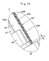
- Denoted at 9 is a housing member on which the air motor 2 and the high voltage generator 7 are mounted.
- This housing member 9 is formed substantially in a cylindrical shape by the use of an electrically insulating synthetic resin material such as POM (polyoxymethylene), PET (polyethylene terephthalate), PEN (polyethylene naphthalate), PP (polypropylene), HP-PE (high pressure polyethylene), HP-PVC(high pressure polyvinyl chloride), PEI (polyether imide), PES (polyether sulfon), or polymethyl pentene.
- POM polyoxymethylene
- PET polyethylene terephthalate
- PEN polyethylene naphthalate
- PP polypropylene
- HP-PE high pressure polyethylene
- HP-PVC high pressure polyvinyl chloride
- PEI polyether imide
- PES polyether sulfon
- the housing member 9 is provided with a cylindrical outer surface 9A around its outer periphery, and formed with a flanged large diameter portion at its rear end 9B.
- a motor receptacle hole 9C is formed in a front side portion of the housing member 9 to accommodate the air motor 2, while a generator receptacle hole 9D is formed in a rear side portion to accommodate the high voltage generator 7.
- a tubular cover member which is provided around the outer surface 9A of the housing member 9 in a radially spaced relation with the latter.
- This cover member 10 is formed of a synthetic resin material with highly insulating and non-water absorbing properties, for example, a synthetic resin material such as PTFE (polytetrafluoroethylene), POM (polyoxymethylene) or PET (polyethylene terephthalate) with surfaces treated with a water repellent agent.
- the tubular cover member 10 is formed in a tubular shape and a predetermined thickness, for example, in a thickness of approximately 0.1mm to 5mm.
- an annular front closing member 11 which is projected radially inward from the inner periphery of the cover member 10 in such a way as to close the front end of the housing member 9.
- annular gap space 12 which is an annular shape in cross section, is formed between the housing member 9 and the cover member 10 in such a way as to circumvent almost entirely the outer peripheries of the air motor 2 and the high voltage generator 7. More specifically, the annular gap space 12 is formed, for example, in a width greater than 5mm between the cover member 10 and the housing member 9 to prevent leak current from the cover member 10 to the housing member 9.
- a shaping air ring which spurts out shaping air.
- This shaping air ring 13 is provided at the fore end (front end) of the cover member 10 through the front closing member 11 in such a way as to enclose the outer periphery of the rotary atomizing head 3.
- the shaping air ring 13 is formed in a tubular shape by the use of a material similar to the cover member 10, for example, by the use of PTFE, POM or PET with surfaces treated with a water repelling agent.
- the rotary atomizing head type coating apparatus of the first embodiment gives the following performances in an electrostatic operation.
- paint is supplied to the rotary atomizing head 3 which is put in high speed rotation by the air motor 2.
- the supplied paint is divided into finely atomized particles and sprayed forward under the influence of centrifugal force resulting from the high speed rotation of the rotary atomizing head 3.
- shaping air is supplied to and spurted out from the shaping air ring 13 to control the spray pattern of paint particles.
- the housing member 9 is assumed to be infinite in volume resistivity, in contrast to the insulating synthetic resin material used for the housing member 9 (a dielectric material), which is approximately in the range of 10 12 ⁇ to 10 16 ⁇ in volume resistivity.
- the housing member 9 is low in electrical resistivity.
- an annular gap space 12 is provided between almost the entire confronting areas of the housing member 9 and the cover member 10.
- the cover member 10 is kept out of contact with the housing member 9 which is lower than air in electrical resistivity.
- high voltage electrostatic charges on the outer surfaces of the cover member 10 are prevented from leakage through the housing member 9, maintaining high voltage electrostatic charges on the cover member 10 to prevent deposition of charged paint particles.
- the atomizer 1 is constituted by the air motor 2 and the rotary atomizing head 3.
- the air motor 2 and the rotary atomizing head 3.
- charged paint particles are released on the outer peripheral side of the housing member 9. These charged paint particles tend to float in the air around the housing member 9.
- the cover member 10 is maintained in an electrostatically charged state by the provision of the annular gap space 12 to generate a Coulomb repulsion force between the cover member 10 and floating charged paint particles, thereby preventing deposition of paint particles on the cover member 10 which is located to enclose the atomizer 1.
- the high voltage generator 7 is adapted to apply a high voltage to the air motor 2. Therefore, by the air motor 2, outer surfaces of the cover member 10 are electrified with a high voltage electrostatic charge in a stable state to prevent deposition of paint particles.
- the cover member 10 is provided as a separate member from the shaping air ring 13.
- the present invention is not limited to this particular embodiment.
- a cover member 10' and a shaping air ring 13' may be integrated into one and single structure.
- the shaping air ring 13 is formed of an electrically insulating synthetic resin material.
- the present invention is not limited to this particular embodiment.
- the shaping air ring 13 may be formed of a conducting metallic material. In this case, a high voltage of the same polarity as charged paint particles is applied to the metallic shaping air ring through the air motor, so that the shaping air ring can act as a repulsive electrode to prevent deposition of charged paint particles against the shaping air ring.
- a rotary atomizing head type coating apparatus according to a second embodiment of the invention.
- This second embodiment has features in that the housing member is constituted by a main housing body extended in forward and rearward directions and adapted to hold a paint atomizing means at a front end thereof and a neck portion branched off the main housing body, and the cover member is constituted by a body cover wrapped around the main housing body and a neck cover wrapped around the neck portion of the housing member.
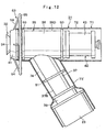
- a robot device for an automatic coating operation This robot device 21 carries out a coating operation automatically by the use of a coater unit 31 which will be described hereinafter.
- the robot device 21 is largely constituted by a base 22, and a robot arm (an arm) 23 which is rotatably and swingably supported on the base 22 and provided with a plural number of articular joints.
- the robot device 21 is capable of moving a coater unit 31 relative to a work piece A, and connected to the earth ground.
- a cartridge type coater unit mounted on the robot device 21, which is largely constituted by an atomizer 32, a housing member 35 and a paint cartridge 42, which will be described hereinafter.
- Denoted at 32 is an atomizer serving as a paint atomizing means for spraying atomized paint particles toward a work piece A which is at the earth potential.
- the atomizer 32 is constituted by an air motor 33 and a rotary atomizing head 34.
- an air motor which is constructed of an electrically conducting metallic material.
- This air motor 33 is constituted by a motor housing 33A, a hollow rotational shaft 33C which is rotatably supported in the motor housing 33A through a static air bearing 33B, and an air turbine 33D which is fixedly mounted on a base end portion of the rotational shaft 33C.
- drive air is supplied to the air turbine 33D of the air motor 33 to rotate the rotational shaft 33C and the rotary atomizing head 34 at a high speed, for example, at a speed of 3,000 r.p.m. to 100,000 r.p.m.
- Designated at 34 is a rotary atomizing head which is mounted on a fore end portion of the rotational shaft 33C of the air motor 33.
- This rotary atomizing head 34 is constructed of, for example, a metallic material or a conducting synthetic resin material.
- paint is supplied to the rotary atomizing head 34 which is put in high speed rotation by the air motor 33, whereupon the supplied paint is atomized and sprayed forward from paint releasing edges 34A at the fore distal end of the rotary atomizing head 34 under the influence of centrifugal force.
- the rotary atomizing head 34 is connected to a high voltage generator 45 which will be described later on.
- a high voltage can be applied to the rotary atomizing head 34 as a whole for imparting a high voltage electrostatic charge directly to paint flowing on surfaces of the rotary atomizing head 34.
- this housing member 35 is a housing member which is adapted to hold the air motor 33 therein.
- this housing member 35 is formed of an electrically insulating synthetic resin material such as POM (polyoxymethylene), PET (polyethylene terephthalate), PEN (polyethylene naphthalate), PP (polypropylene), HP-PE (high pressure polyethylene), HP-PVC (high pressure polyvinyl chlorine), PEI (polyether imide), PES (polyether sulfon), or polymethyl pentene.
- POM polyoxymethylene
- PET polyethylene terephthalate
- PEN polyethylene naphthalate
- PP polypropylene
- HP-PE high pressure polyethylene
- HP-PVC high pressure polyvinyl chlorine
- PEI polyether imide
- PES polyether sulfon
- the housing member 35 is composed of a cylindrical main housing body 36 which is extended in an axial direction (i.e., in forward and rearward directions), and a neck portion 37 which is branched out in an obliquely downward direction at an axially intermediate position on the outer periphery of the main housing body 36.
- a motor receptacle hole 36A is formed in a front side portion of the main housing body 36 to accommodate the air motor 33 therein, while a container receptacle hole 36B is formed in a rear end portion of the main housing body 36 to hold a container 43 of a paint cartridge 42 which will be described hereinafter. Further, a feed tube passage hole 36C is formed internally of the main housing body 36, axially through centers of the motor receptacle hole 36A and the container receptacle hole 36B.
- a generator receptacle hole 37A is formed in the neck portion 37 to accommodate a high voltage generator 45 which will be described hereinafter.
- a lower proximal end of the neck portion 37 is attached to the distal end of the robot arm 23 of the robot device 21 by means of a tubular connector member 38 which is formed of an insulating synthetic resin material.
- an air passage 39 is formed internally of the housing member 35 to supply drive air to the air motor 33, along with an extending liquid passage 40 which supplies an extending liquid to the paint cartridge 42, which will be described later, for controlling the quantity of paint discharge.
- a shaping air ring which is provided at the fore end of the main housing body 36 of the housing member 35 in such a way as to circumvent the rotary atomizing head 34.
- This shaping air ring 41 is formed, for example, of an electrically conducting metallic material, and electrically connected to the air motor 33.
- a plurality of air outlet holes 41A are bored in the shaping air ring 41 to spurt out shaping air toward paint which is sprayed from the rotary atomizing head 34.
- This paint cartridge 42 is largely constituted by an axially extending tubular (cylindrical) container 43, a feed tube 44 axially extending from the container 43, and a piston defining a paint chamber and an extending liquid chamber (both not shown) within the container 43.
- the paint cartridge 42 is set in the container receptacle hole 36B of the housing member 35, with the feed tube 44 placed in the feed tube passage hole 36C.
- an extending liquid is supplied to the extending liquid chamber through the extending liquid passage 40 of the housing member 35 thereby putting the piston in a sliding displacement to deliver paint in the container 43 to the rotary atomizing head 34 through the feed tube 44.
- the paint cartridge 42 is dismantled from the container receptacle hole 36B and attached to a paint replenisher (not shown), and then paint is refilled into the paint chamber of the container 43 through the feed tube 44.
- Indicated at 45 is a high voltage generator which is accommodated in the neck portion 37 of the housing member 35 to serve as a high voltage application means.
- Input side of the high voltage generator 45 is connected to an external high voltage controller 46 through the robot device 21, while its output side is connected to the air motor 33.
- the high voltage generator 45 is constituted, for example, by a multi-stage rectification circuit (so-called Cockcroft circuit) composed of a plurality of capacitors and diodes (both not shown).
- the high voltage generator 45 by elevating a DC source voltage which is supplied from the high voltage controller 46, the high voltage generator 45 generates a high voltage, for example, in the range of -30kV to -150kV. At this time, the output voltage of the high voltage generator 45 is determined depending upon the level of the source voltage which is supplied from the high voltage controller 46, that is to say, the output voltage (a high voltage) of the high voltage generator 45 is controlled by the high voltage controller 46.
- the high voltage generator 45 is connected to the air motor 33 and the rotary atomizing head 34 to impart a high voltage electrostatic charge directly to paint.
- a cover member which is arranged to enshroud outer surfaces of the housing member 35.
- This cover member 47 is formed of an electrically insulating fluorine-base synthetic resin which is high in insulating performance and non-hydrophilic, for example, a fluorine-base synthetic resin such as PTFE (polytetrafluoroethylene) and ETFE (a copolymer of ethylene and tetrafluoroethylene).
- PTFE polytetrafluoroethylene
- ETFE a copolymer of ethylene and tetrafluoroethylene
- the cover member 47 is composed of a body cover 48 enclosing outer surfaces 36D of the main housing body 36 and a neck cover 49 enclosing outer surfaces 37B of the neck portion 37.
- Each one of the covers 48 and 49 is formed by rolling a 0.1mm - 5mm thick synthetic resin film into a tubular shape.
- the body cover 48 around the circumference of the main housing body 36 is extended further rearward to enclose not only the outer surface 36D of the main housing body 36 but also the outer surface of the container 43 of the paint cartridge 42. Further, the body cover 48 is fitted and attached on annular flanges 50 which are provided at the fore and rear ends of the main housing body 36. On the other hand, the neck cover 49 is fitted and attached on an annular flange 51 which is provided in a longitudinally intermediate portion of the neck portion 37, and the connector member 38 which is provided at the lower proximal end of the neck portion 37.
- annular gap space 52 which is in an annular shape in cross-section, is formed between the main housing body 36 and the body cover 48, and between the neck portion 37 and the neck cover 49. That is to say, the annular gap space 52 is formed between almost entire confronting areas of the cover member 47 and the housing member 35.
- the air motor 33 and high voltage generator 45 are almost entirely circumvented by the annular gap space 52.
- the annular gap space 52 is formed in a width greater than 5mm between the cover member 47 and the housing member 35 in order to prevent leak current from the cover member 47 to the housing member 35.
- This high voltage discharge electrode assembly 53 is a high voltage discharge electrode assembly which is located on the outer peripheral side of the body cover 48.
- This high voltage discharge electrode assembly 53 is formed of a conducting material, and constituted by support arms 54 and a ring member 55, which will be described hereinafter.
- Denoted at 54 are radial support arms which are provided around the shaping air ring 41. These support arms 54 are extended radially outward from the side of the housing member 35 toward a point on the outer peripheral side of the body cover 48. Four-support arms 54, for example, are provided at uniform angular intervals around the shaping air ring 41 to support a ring member 55 thereon.
- Indicated at 55 is a ring member which is supported on distal ends of the support arms 54.
- This ring member 55 is formed in the shape of a ring by the use of a conducting material like a metal, for example. Further, the ring member 55 is located around the air motor 33 in such a way as to circumvent a front portion of the body cover 48.
- the ring member 55 is formed in a circular shape which is larger than the outside diameter of the body cover 48, and located in substantially concentric relation with the rotational shaft 33C of the air motor 33. As a consequence, the ring member 55 is located substantially at the same distance from the body cover 48 at any point around its circular body.
- the ring member 55 is connected to the air motor 33 through the support arms 54 and the shaping air ring 41.
- a high voltage is applied to the ring member 55 from the high voltage generator 45 to discharge ions of the same polarity as charged paint particles from the ring member 55.
- the rotary atomizing head type coating apparatus of the second embodiment gives the following performances in an electrostatic coating operation.
- the robot device 21 As a work piece A is delivered to a position in the proximity of the robot device 21 by a conveyer or the like, the robot device 21 is put in a playback action according to uploaded teaching actions, moving the coater unit 31 to the proximity of the work piece A.
- the rotary atomizing head 34 on the coater unit 31 is put in high speed rotation by the air motor 33, and paint is supplied to the rotary atomizing head 34 from the container 43 through the feed tube 44.
- paint is sprayed forward in the form of finely atomized particles by the coater unit 31.
- the spray pattern of paint particles is controlled by shaping air which is spurted out from the shaping air ring 41.
- a high voltage is applied to the rotary atomizing head 34 from the high voltage generator 45 through the air motor 33. Therefore, the paint which has been supplied to the rotary atomizing head 34 is imparted with a high voltage electrostatic charge directly by the rotary atomizing head 34, and charged paint particles are urged to fly toward and deposit on the work piece A, traveling along an electrostatic field which is formed between the rotary atomizing head 34 and the work piece A which is at the earth potential.
- the high voltage discharge electrode assembly 53 is provided on the outer peripheral side of the body cover 48. Therefore, the high voltage from the high voltage generator 45 is applied to the ring member 55 through the air motor 33, and discharged from the ring member 55.
- ions of the same polarity as charged paint particles are discharged from the high voltage discharge electrode assembly 53, certainly electrifying the cover member 47 with an electrostatic charge of the same polarity.
- electrostatically attenuated paint particles can be re-electrified with a high voltage electrostatic charge.
- repulsion force occurs between re-electrified paint particles and the high voltage discharge electrode assembly 53 or the cover member 47, preventing deposition of paint particles on the cover member 47 in an assured manner.
- the annular gap space 52 is provided between almost the entire confronting areas of the housing member 35 and the cover member 47 which confront face to face each other in the radial direction.
- air is assumed to have an infinite volume resistivity, in contrast to an insulating synthetic resin material used for the housing member 35 (a dielectric material), which is approximately in the range of 10 12 ⁇ to 10 16 ⁇ in volume resistivity.
- the housing member 35 is low in volume resistivity.
- the cover member 47 is kept out of contact with the housing member 35 by the annular gap space 52 which is provided between these two members, to suppress leaks through the housing member 35 of high voltage electrostatic charges on the outer surface of the cover member 47.
- the cover member 47 can be maintained in an electrostatically charged state to prevent deposition of charged paint particles.
- part of charged paint particles which have been sprayed from the rotary atomizing head 34 may have a tendency to float in the air around the outer periphery of the cover member 47 during a coating operation.
- the cover member 47 can be maintained in an electrostatically charged state by the annular gap space 52, Coulomb repulsion force occurs between the electrostatic charge on the cover member 47 and floating charged paint particles, acting to stop paint particles from depositing on the cover member 47 enclosing the atomizer 32.
- the high voltage generator 45 a high voltage is applied to the air motor 33, the rotary atomizing head 34 and the shaping air ring 41. Therefore, high voltage electrostatic charges are built up in a stable state on outer surfaces of the cover member 47 by the air motor 33, thereby preventing deposition of paint particles.
- the cover member 47 is composed of the body cover 48 enclosing the main housing body 36 of the housing member 35 and the neck cover 49 enclosing the neck portion 37 of the housing member 35. That is to say, the entire outer surfaces of the housing member 35 are enshrouded by the body cover 48 and the neck cover 49. Thus, deposition of charged paint particles can be prevented by building up electrostatic charges on the outer surfaces of the body cover 48 and the neck cover 49.
- the cover member 47 which is formed of a fluorine-base synthetic resin film can employ, for example, PTFE with water repellent properties for the purpose of preventing deposition of charged paint particles on the outer surfaces of the cover member 47.
- the fluorine-base synthetic resin film of the cover member 47 can be electrified to generate a repulsion force against charged paint particles.
- the fluorine-base synthetic resin film is low in moisture absorption and high in volume resistivity, so that leaks of electrostatic charges from the cover member 47 hardly take place. Thus, the electrostatically charged state of cover member 47 can be maintained in a stable and assured manner.
- the filmy cover member 47 can be stripped off the housing member 35 and replaced by a fresh cover film easily.
- the time for maintenance and service of the coater unit 31 can be shortened a considerable degree, permitting to carry out a coating operation with higher productivity as compared with the conventional machines which require to wash or clean a housing member 35 in the event of paint deposition.
- the high voltage discharge electrode assembly 53 is provided on the outer peripheral side of the body cover 48, and a high voltage is applied to the ring member 55 from the high voltage generator 45 through the air motor 33 and shaping air ring 41 and discharged from the ring member 55. At this time, ions of the same polarity as charged paint particles are discharged from the high voltage discharge electrode assembly 53, electrifying the cover member 47 with a high voltage electrostatic charge in an assured manner. By the electrical discharge from the ring member 55, the high voltage discharge electrode assembly 53 contributes to recharging of electrostatically attenuated paint particles.
- a repulsion force occurs between recharged paint particles and the high voltage discharge electrode assembly 53 or the cover member 47, acting to keep charged paint particles away from the cover member 47 and thus preventing charged paint particles from depositing on the cover member 47.
- the high voltage discharge electrode assembly 53 which is constituted by the support arms 54 and the ring member 55 can form a high voltage electrostatic field around the cover member 47 by the ring member 55 which is located around the body cover 48, and charged paint particles are kept off the cover member 47.
- the ring member 55 which circumvents the body cover 48 can impart a high voltage electrostatic charge to the cover member 47 by high voltage electrical discharge over a far broader areas as compared with a case where the high voltage discharge electrode assembly 53 is omitted. Thus, deposition of charged paint particles on the cover member 47 can be prevented over broader surface areas.
- a rotary atomizing head type coating apparatus according to a third embodiment of the invention.
- This third embodiment has features in that a body cover is formed of a fluorine-base synthetic resin film while a neck cover is formed of a laminated film having a semi-conducting film sandwiched between two insulating films.
- those component parts which are identical with the counterparts in the foregoing second embodiment are simply designated by the same reference numerals or characters to avoid repetitions of same descriptions.
- a cover member which is arranged to wrap in outer surfaces of a housing member 35.
- This cover member 61 is composed of a body cover 62 enclosing an outer surface 36D of a main housing body 36 and a container 43, and a neck cover 63 enclosing an outer surface 37B of a neck portion 37.
- the body cover 62 is formed of a fluorine-base synthetic resin film, for example, a PTFE film.
- the neck cover 63 is formed of a laminated film material having a semi-conducting film 63C sandwiched between two insulating films 63A and 63B.
- the insulating films 63A and 63B are formed, for example, by the use of a fluorine-base synthetic resin material like PTFE with a volume resistivity greater than, for example, 10 16 ⁇ .
- the semi-conducting film 63C is formed by the use of a synthetic resin material like polyethylene which is lower in resistivity than the insulating films 63A and 63B, for example, a synthetic resin material having a volume resistivity lower than 10 11 ⁇ .
- these films 63A, 63B and 63C are preferred to have a thickness in the range of 0.1mm to 1.0mm, more preferably, a thickness in the range of 0.1mm to 0.3mm.
- the body cover 62 is fitted and attached on annular flanges 50 which are provided at fore and rear longitudinal ends of the main housing body 36.
- the neck cover 63 is fitted and attached on an annular flange 51, which is provided at a longitudinally intermediate portion of the neck portion 37, and a connector member 38 which is provided at the lower proximal end of the neck portion 37.
- annular gap space 64 is formed between almost the entire confronting areas of the cover member 61 and the housing member 35.
- the distal end of the neck cover 63 is extended toward the proximal end of the neck portion 37 and held in contact with the robot arm 23.
- the insulating films 63A and 63B of the neck cover 63 are held in contact with the robot arm 23, but the semi-conducting film 63C is cut short of and spaced from the robot arm 23 by a distance L greater than 10mm.
- electrostatic charges on the semi-conducting film 63C of the neck cover 63 are prevented from being discharged to the side of the robot arm 23 which is at the earth potential.
- the third embodiment of the invention can produce the same operational effects as the foregoing second embodiment.
- the body cover 62 is formed of a fluorine-base synthetic resin material while the neck cover 63 is formed of a laminated film material.
- a high voltage is applied to the atomizer 32, shaping air ring 41 and high voltage discharge electrode assembly 53 from the high voltage generator 45. Therefore, the body cover 62 which is located in the proximity of the atomizer 32 is easily electrified by an electrostatic charge. That is to say, in this case, paint deposition on the body cover 62 can be easily suppressed.
- the neck cover 63 which is located at a greater distance from the atomizer 32 is less susceptible to electrification.
- uniformity of electrostatic charges which deposit on the surface of the cover member 61 largely depends on the potential within the cover member 61.
- the neck cover 63 is formed of a laminated film having a semi-conducting film 63C sandwiched between two insulating films 63A and 63B.
- electrostatic charges can migrate more easily in the semi-conducting film 63C which is smaller in volume resistivity as compared with the insulating films 63A and 63B.
- the semi-conducting film 63C which is sufficiently low in electric resistivity as compared with the insulating films 63A and 63B is held at the same potential in all of its localities.
- This stability in potential of the underlying semi-conducting film 63C has an effect of electrifying surfaces of the insulating film 63A uniformly with an electrostatic charge.
- the provision of the semi-conducting film 63C helps to electrify the surface of the insulating film 63A uniformly with negative charges in an assured manner. Therefore, when negative ions come flying toward the insulating film 63A, a build up of electrostatic charges takes place uniformly over the entire surface of the insulating film 63A.
- the semi-conducting film 63C is partly removed at the lower distal end of the neck cover 63, insulating the semi-conducting film 63C from the robot arm 23.
- the present invention is not limited to this particular arrangement.
- a semi-conducting film 63C' can be insulated from the robot arm 23 by welding marginal end portions of insulating films 63A' and 63B' at the lower distal end of a neck cover 63'.
- FIG. 11 Shown in Fig. 11 is a rotary atomizing head type coating apparatus according to a fourth embodiment of the present invention.
- This fourth embodiment of the invention has a feature in that a neck cover is extended toward a robot arm beyond the lower proximate end of the neck portion of the housing member and arranged to enshroud the robot arm as well.
- those component parts which are identical with the counterparts in the foregoing second embodiment are simply designated by the same reference numerals or characters to avoid repetitions of same explanations.
- a cover member which is arranged to enshroud outer surfaces of the housing member 35.
- This cover member 71 is composed of a body cover 72 enshrouding the outer surface 36D of the main housing body 36 as well as outer surface of the container 43 of a paint cartridge, and a neck cover 73 enshrouding the outer surface 37B of the neck portion 37.
- the body cover 72 is formed of a film of a fluorine-base synthetic resin material, for example, such as PTFE.
- the neck cover 73 is formed of a laminated film material having a semi-conducting film sandwiched between two insulating films.
- the body cover 72 is fitted and attached on annular flanges 50 which are provided at fore and rear ends of the main housing body 36, and the neck cover 73 is fitted and attached on an annular flange 51, which is provided in a longitudinally intermediate portion of the neck portion 37, and a connector member 38 which is provided at a lower proximal end of the neck portion 37. Except minimal areas which are in contact with the flanges 50, almost entire areas of the body cover 72 which radially confront face to face with outer surface 36D of the main housing body 36 are radially spaced from and kept out of contact with the latter.
- annular gap space 74 is formed between almost the entire confronting areas of the cover member 71 and the housing member 35.
- the neck cover 73 is extended beyond the neck portion 37 onto the robot arm 23 to circumvent a fore end portion of the robot arm 23.
- the neck cover 73 is gradually spread in diameter in a direction toward its lower distal end, presenting a bell-like shape. Namely, the neck cover 73 is spread in diameter toward and radially spaced from a fore end portion of the robot arm 23 which is at the earth potential. Keeping a sufficient distance of insulation from the robot arm 23, the neck cover 73 functions to prevent discharges and leaks of electrostatic charges toward the robot arm 23.
- the fourth embodiment can produce substantially the same operational effects as the foregoing second and third embodiments.
- the lower end of the neck cover 73 is arranged to enshroud a fore end portion of the robot arm 23 as well, by extending the neck cover 73 beyond the neck portion 37 of the housing member 35 toward and around the robot arm 23 which is at the earth potential.
- the extended end of the neck cover 73 is spaced from and kept out of contact with the robot arm 23 which is at the earth potential.
- the neck cover 73 is arranged to enshroud the outer periphery of the robot arm 23 as well, preventing charged paint particles from depositing on the robot arm 23 even if the robot arm 23 is at the earth potential.
- the neck cover 73 is gradually spread in diameter in a direction toward the robot arm 23, presenting a bell-like shape, and as a result spaced from the robot arm 23 in the radial direction.
- the present invention is not limited to this particular arrangement.
- a neck cover 73' of a straight tubular shape which is fitted around the robot arm 23 keeping a constant distance from the robot arm in the axial direction.
- a rotary atomizing head type coating apparatus according to a fifth embodiment of the invention.
- This fifth embodiment has a feature in that a cover member is entirely formed of laminated film material.
- those component parts which are identical with the counterparts in the foregoing second embodiment are simply designated by the same reference numerals or characters to avoid repetitions of same explanations.
- a cover member which is fitted around the housing member 35 to cover the outer surfaces of the latter.
- this cover member 81 is formed of a laminated film material having a semi-conducting film sandwiched between two insulating films.
- the cover member 81 is composed of a body cover 82 enclosing outer surface 36D of the main housing body 36 and a neck cover 83 enclosing outer surface 37B of the neck portion 37.
- an annular gap space 84 is formed between almost the entire confronting areas of the cover member 81 and the housing member 35.
- the fifth embodiment of the invention can produce substantially the same operational effects as the second and third embodiments.
- the cover member 81 which is entirely formed of a laminated film, even when electric charges are hardly built up on part of the cover member 81 due to a gradient of potential in the housing member 35, for example, the entire semi-conducting film of the cover member 81 can be stabilized almost at the same potential to suppress the influence of the gradient of potential in the housing member 35.
- FIG. 14 and 15 there is shown a rotary atomizing head type coating apparatus according to a sixth embodiment of the invention.
- This sixth embodiment has a feature in that acicular electrode members are provided on a ring member of a high voltage discharge electrode assembly, the acicular electrode members being extended in a direction away from a work piece.
- those component parts which are identical with the counterparts in the foregoing second embodiment are simply designated by the same reference numerals or characters to avoid repetitions of same explanations.
- a high voltage discharge electrode assembly which is provided on the outer peripheral side of a body cover 48.
- This high voltage discharge electrode assembly is formed of a conducting material and composed of support arms 92, a ring member 93 and electrode members 94, which will be described hereinafter.
- radial support arms which are located around the outer periphery of a shaping air ring 41. These support arms 92 are extended radially outward from the side of a housing member 35 toward a point on the outer peripheral side of the body cover 48. Further, a plural number of support arms 92, for example, four support arms 92 are located at uniform angular intervals around the shaping air ring 41 to support a ring member 93 on their outer distal ends.
- a ring member which is supported on outer distal ends of the support arms 92.
- This ring member 93 is formed, for example, in the shape of a circular ring by the use of an electrically conducting material like a metal. Further, the ring member 93 is positioned around the air motor 33 in such a way as to circumvent a front portion of the body cover 48. Furthermore, the ring member 93 is formed in a circular shape which is larger than outside diameter of the body cover 48 and positioned substantially in concentric or coaxial relation with the rotational shaft 33C of the air motor 33. Thus, all around the circular body, the ring member 93 is positioned constantly at the same distance from the body cover 48. Further, the ring member 93 is connected to the air motor 33 through the support arms 92 and shaping air ring 41. Therefore, from the high voltage generator 45, a high voltage is applied to the ring member 93.
- Electrodes 94 are electrode members which are provided on the ring member 93. These electrode members 94 are extended out from the ring member 93 in a direction away from a work piece (in rearward direction), and are each in the form of an acicular electrode formed of an electrically conducting material like a metal. A plural number of electrode members 94 are provided in equidistant positions on the round body of the ring member 93. Relative to the axis of the air motor (the rotational shaft), each one of the electrode members 94 is extended in a parallel direction or with an angle of depression in the range of 10° or an angle of elevation in the range of 20°.
- the sixth embodiment of the invention can produce substantially the same operational effects as the second embodiment.
- an electric field can be concentrated at the distal end of each electrode member 94 to discharge a high voltage easily in a stabilized manner.
- the cover member 47 is imparted with a high voltage electrostatic charge up to its rear end portions. Thus, deposition of charged paint particles can be prevented on broader areas of the cover member 47.
- a plural number of acicular electrode members 94 are provided on the ring member 93.
- the present invention is not limited to this particular arrangement.
- a discharge ring as in the fourth modification shown in Figs. 16 and 17 .
- a discharge ring is constituted by a ring member 93' and an electrode member 94' in the form of a circular blade which is projected rearward from all around the ring member 93'.
- the blade electrode member 94' can be formed simply folding a single blade into a circular ring.
- the electrode member 94' in the shape of a blade may be provided on both of front and rear sides of the ring member 93', that is, on the side facing toward a work piece and on the other side facing away from a work piece.
- the blade-like electrode member 94' may be provided only on the rear side of the ring member 93', that is, only on the side away from a work piece.
- a rotary atomizing head type coating apparatus according to a seventh embodiment of the invention.
- This embodiment has a feature in that the coater unit is attached to a robot arm by way of a housing member which has no branched neck portion.
- those component parts which are identical with the counterparts in the foregoing second embodiment are simply designated by the same reference numerals or characters to avoid repetitions of same explanations.
- This coater unit 101 is attached to a fore distal end of a robot arm 23, and largely constituted by an atomizer 32 and a housing member 102.
- housing member 102 is a housing member adopted in the seventh embodiment. Substantially in the same way as the housing member 9 in the first embodiment, this housing member 102 is formed generally in a cylindrical shape by the use of an electrically insulating synthetic resin material, and adapted to accommodate an atomizer 32 and a high voltage generator 45.
- a motor receptacle hole 102A is formed internally of a front side portion of the housing member 102 to accommodate an air motor 33, while a generator receptacle hole 102B is provided internally of a rear side portion of the housing member 102 to accommodate a high voltage generator 45.
- a shaping air ring 41 of a conducting metallic material is attached to the fore end of the housing member 102.
- rear end of the housing member 102 attached to a fore distal end of a robot arm 23.
- a high voltage discharge electrode assembly 53 located on the outer peripheral side of the shaping air ring 41 is a high voltage discharge electrode assembly 53 which is constituted by support arms 54 and a ring member 55.
- Denoted at 103 is a cover member of a tubular shape which is fitted on in such a way as to enshroud outer surface 102C of the housing member 102.
- this cover member 103 is formed in a tubular shape by the use of a fluorine-base synthetic resin film material, and extended axially along the housing member 102 as far as a position around a fore distal end of the robot arm 23.
- the cover member 103 is arranged to enshroud the outer surface 102C of the housing member 102 and the outer surface of the robot arm 23 as well.
- the cover member 103 is fitted on and attached to annular flanges 104 which are provided around fore and rear end portions of the housing member 102. Except minimal areas which are in contact with the flanges 104, almost entire areas of the cover member 103 which are disposed face to face with the outer surface 102C of the housing member 102 are spaced from and kept out of contact with the housing member 102. Thus, an annular gap space 105, which is an annular shape in cross section, is formed between almost entire confronting areas of the cover member 103 and housing member 102. As a consequence, on the outer peripheral side, the air motor 33 and high voltage generator 45 are almost entirely circumvented by the annular gap space 105.
- the seventh embodiment of the invention can produce substantially the same operational effects as the second and fourth embodiments.
- FIG. 19 there is shown a rotary atomizing head type coating apparatus according to an eighth embodiment of the invention.
- This embodiment has a feature in that a high voltage generator is adapted to apply a high voltage to an external electrode assembly which is located on the outer peripheral side of a cover member.
- those component parts which are identical with the counterparts in the foregoing second embodiments are simply designated by the same reference numerals or characters to avoid repetitions of same explanations.
- coater unit 111 is attached to a distal end of the robot arm 23, and largely constituted by an atomizer 32 and a housing member 112.
- Denoted at 112 is a housing member which is adopted in the eighth embodiment.
- This housing member 112 is formed substantially in a cylindrical shape by the use of an electrically insulating synthetic resin material to mount the atomizer 32.
- a motor receptacle hole 112A is formed internally of a front side portion of the housing member 112 to accommodate an air motor 33.
- a shaping air ring 41 is attached to the fore end of the housing member 112. In turn, rear end of the housing member 112 is attached to a distal end of the robot arm 23.
- Indicated at 113 is a cover member of a tubular shape which is fitted on in such a way as to enshroud outer surface 112B of the housing member 112.
- this cover member 113 is formed in a tubular shape by the use of a fluorine-base synthetic resin film material.
- the cover member 113 is extended axially along the housing member 112 as far as a position around a fore distal end portion of the robot arm 23.
- the cover member 113 is arranged to enshroud the outer surface 112B of the housing member 112 and outer surface of the robot arm 23 as well.
- cover member 113 is fitted on and attached to annular flanges 114 which are provided at and around fore and rear end portions of the housing member 112. Except minimal areas which are in contact with the flanges 114, almost entire areas of the cover member 113 which are confronted face to face by the outer surface 112B of the housing member 112 are radially spaced from and kept out of contact with the latter. Thus, an annular gap space 115, which is an annular shape in cross section, is formed between almost the entire confronting areas of the cover member 113 and the housing member 112. On the outer peripheral side, the air motor 33 and high voltage generator 45 are almost entirely circumvented by the annular gap space 115.
- Indicated at 116 is an external electrode assembly which is located on the outer peripheral side of the housing member 112, and constituted by support arms 117, electrode support members 118 and acicular electrode members 119, which will be described hereinafter.
- Indicated at 117 are a plural number of support arms which are provided on a rear side portion of the housing member 112. These support arms 117 are disposed radially relative to the rotational shaft 33C of the air motor 33 and extended radially outward of the housing member 112.
- Denoted at 118 are electrode support members which are provided at outer distal ends of the support arms 117 and extended forward to have the respective fore distal ends located around the rotary atomizing head 34.
- An acicular electrode member 119 is projected forward from the fore distal end of each electrode support member 118.
- the acicular electrode members 119 are connected to an external high voltage generator 45 through the electrode support members 118, support arms 117 and a robot arm 23, for applying a high voltage from the high voltage generator 45 to the respective acicular electrode members 119.
- the eighth embodiment of the invention can produce substantially the same operational effects as the foregoing second embodiment.
- a high voltage is applied from a high voltage generator 45 to the external electrode assembly 116 which is located around the cover member 113.
- an ionization zone is formed around the rotary atomizing head 34 by the external electrode assembly 116, indirectly imparting an electrostatic charge to paint particles which are sprayed by the rotary atomizing head 34.
- a high electrostatic charge is built up on outer surfaces of the cover member 113 in a stable state to prevent deposition of paint particles.
- the cover member 47, 103 or 113 is described as being formed of a film of a fluorine-base synthetic resin material.
- the cover member may be formed of a laminated film material having a semi-conducting film sandwiched between two insulating films.
- the cover member 47, 103 or 113 is described as being formed of a film of a fluorine-base synthetic resin material.
- the cover member may use a polyethylene resin film formed of a polyethylene resin material if desired.
- the body cover 62 or 72 which is described as being formed of a fluorine-base synthetic resin film material in the third and fourth embodiments may be formed of a polyethylene resin film material if desired.
- the neck cover 83 or 49 of the cover member 81 or 47 is fitted on to cover the neck portion 37 of the housing member 35 alone.
- the neck cover may be arranged to cover a fore distal end portion of the robot arm 23 in the same way as in the fourth embodiment.
- the neck cover 63 or 73 and cover member 81 are formed of a laminated film material having semi-conducting film 63C sandwiched between two insulating films 63A and 63B.
- the present invention is not limited to this particular arrangement.
- one insulating film on the side of the housing member (on the inner side) may be omitted, for example, if discharges from the semi-conducting film can be prevented.
- conducting shaping air ring 41 in the second to eighth embodiments may be replaced by an insulating shaping air ring similar to the one employed in the first embodiment.
- the high voltage discharge electrode assembly 53 or 91 which is located around the shaping air ring 41 in the second to seventh embodiments may be omitted if necessary.
- the cover member 113 is arranged to cover the circumference of the housing member 112 and the robot arm 23 as well.
- the present invention is not limited to this particular arrangement.
- a cover member 113' which is arranged to cover the support arms 117 and electrode support members 118 of the external electrode assembly 116 in addition to the circumference of the housing member 112 and robot arm 23, to prevent deposition of paint particles on the external electrode assembly 116.
- the housing member 35, 102 or 112 of the coater unit 31, 101 or 111 is attached to the robot arm 23 of a robot device 21 which moves in various directions.
- the present invention is not limited to this particular arrangement.
- the housing member may be mounted on an arm of a reciprocator which is put in reciprocating movements in one direction.
- the housing member may be mounted on an arm which is immovably fixed like a coater support stand.
- the present invention is applied to a rotary atomizing head type coating apparatus (rotary atomizing type electrostatic paint coating apparatus) with a rotary atomizing head 3 or 34 for atomizing and spraying paint.
- rotary atomizing head type coating apparatus rotary atomizing type electrostatic paint coating apparatus
- rotary atomizing head 3 or 34 for atomizing and spraying paint.
- the present invention is not limited to coating apparatuses of this type.
- the present invention is similarly applicable to electrostatic coating apparatuses other than the rotary atomizing head type, for example, to electrostatic coating apparatuses such as pneumatic or hydraulic atomizing type electrostatic coating apparatuses.
Landscapes
- Electrostatic Spraying Apparatus (AREA)
Description
- This invention relates to an electrostatic coating apparatus which is adapted to spray paint under application of a high voltage.
- Generally, there has been known an electrostatic coating apparatus which is constructed of, for example, an atomizer consisting of an air motor and a rotary atomizing head, a housing member formed of an electrically insulating material and adapted to hold the air motor of the atomizer in position, a tubular cover member arranged to cover outer surfaces of the housing member, and a high voltage generator adapted to electrify atomized paint particles with a negative high voltage electrostatic charge as the paint particles are sprayed forward from the rotary atomizing head of the atomizer by using external electrode assembly (e.g., Japanese Patent Laid-Open No.
2001-113207 - In electrostatic coating apparatuses of this sort, an electrostatic field is formed by lines of electric force between an external electrode, to which a negative high voltage is applied, and a rotary atomizing head which is held at the earth potential, and between the external electrode and a work piece. Besides, a negative ionization zone is formed in the vicinity of a fore distal end of the external electrode assembly.
- If, in this state, paint is sprayed by a rotary atomizing head which is put in high speed rotation, sprayed paint particles are electrified by application of a negative high voltage during travel through the ionization zone to become negatively charged paint particles. As a result, the charged paint particles are urged to fly toward and deposit on surfaces of a work piece which is connected to the earth.
- In the case of the electrostatic coating apparatus of above-mentioned Japanese Patent Laid-Open No.
2001-113207 - However, actually, as an electrostatic coating operation is continued, paint particles start to gradually deposit on outer surfaces of the cover member and remain there as a paint deposit. This paint deposit is problematic in that it gives rise to degradations in insulating performance of the outer surface of the cover member. Degradations in insulating performance of the cover member are reflected by paint deposition progressing at an abruptly increasing rate. Therefore, it is often the case with conventional electrostatic coating apparatuses that coating operations are interrupted frequently for removal of paint deposits.
- Further, in the electrostatic coating apparatus according to the above-mentioned Japanese Patent Laid-Open No.
2001-113207 -
EP 1 393 816 A1 -
EP 1 886 734 A1 -
EP 1 114 677 A1head changer 1 and connecting same to the common main assembly body. - In view of the above-discussed problems with the prior art, it is an object of the present invention to build up high voltage electrostatic charges on outer surfaces of a cover member constantly in a stable state to prevent deposition of paint particles.
- (1) According to the present invention, in order to achieve the above-stated objective, there is provided an electrostatic coating apparatus constructed of a paint atomizing means adapted to spray atomized paint particles toward a work piece, a housing member formed of an insulating material and holding the paint atomizing means in position, a tubular cover member formed in cylindrical shape by an insulating material and arranged to enshroud outer surfaces of the housing member, and a high voltage application means adapted to electrify sprayed paint particles from the paint atomizing means with a high voltage electrostatic charge, urging charged paint particles to fly toward and deposit on the work piece, characterized in that the electrostatic coating apparatus comprises a spacing provided between and around almost entire radially confronting areas of the housing and cover members.
Generally, as compared with air, the housing which is formed of an electrically insulating material is low in electrical resistivity. Therefore, a spacing is provided between almost entire confronting areas of the housing member and the cover member, reducing contacting areas of the cover member with the housing member which is lower than air in electrical resistivity, suppressing leaks of high voltage electrostatic charges on outer surfaces of the cover member through the housing member and thus maintaining the cover member in an electrified state to prevent deposition of charged paint particles. - (2) According to the invention, the cover member is formed of a laminated film material having a semi-conducting film sandwiched between two insulating films.
In this case, the semi-conducting film as a whole stabilizes substantially at the same potential because static charges can migrate within the semi-conducting film. The stability in potential of the semi-conducting film has an effect that an electrostatic charge can be built up more uniformly on the surface of an overlying insulating film.
Namely, when an electrostatic charge of negative polarity is built up on a surface on the front side of an insulating film, an electrostatic charge of positive polarity occurs on a surface on the back side of the insulating film due to a dielectric electrification phenomenon. At this time, positive charges on the back side of the insulating film which is in contact with the semi-conducting film are allowed to move within the semi-conducting film and spread over the entire cover member. As a result, negatively charged ions on the front side of the insulating film are also spread uniformly over the entire cover member under the influence of the Coulomb force against a positive charge.
Thus, negative electrostatic charge can be imparted to the surface of the insulating film more uniformly as compared with a cover without a semi-conducting film. Therefore, a repulsion force can be generated constantly between the insulating film and charged paint particles to reduce dirty spots which would otherwise appear as a result of localized paint deposits.
Accordingly, even in a situation where a build up of electrostatic charges hardly takes place in certain localities of the cover member under the influence of a gradient of potential in the cover member, the semi-conducting film comes to have the same potential, eliminating the influence of the gradient of potential in the cover member, which would affect a uniform build up of electrostatic charges on the insulating film on the side of the outer surface. As a consequence, when negative ions come flying toward the cover member, an electrostatic charge can be built up uniformly on the entire outer surfaces of the cover member in an assured manner to prevent deposition of charged paint particles, while preventing concentration of an electric field for prevention of deposition or accumulation of paint in certain localized areas. - (3) According to the invention, the housing member is formed in a columnar shape and adapted to hold the paint atomizing means in a front side portion, rear end of the columnar housing member being attached to and supported on a support arm, and the cover member is extended toward the support arm beyond the housing member to cover the support arm.
In this case, the cover member is extended toward the support arm of a robot device beyond a proximal end of the housing member, enshrouding a fore distal end portion of the support arm as well. Thus, even in case the support arm is connected to the earth ground, charged paint particles are prevented from depositing on the grounded support arm.
Further, since a distal end of the cover member can be located at a space from the support arm which is at the earth potential, there is no possibility of leakage of electrostatic charges from the cover member to the support arm even when surfaces of the cover member are smeared with paint to some extent. Therefore, the cover member is maintained in an electrified state in an assured manner to prevent growth of smeared spots. - (4) According to the present invention, the electrostatic coating apparatus further comprises a high voltage discharge electrode assembly located on the outer peripheral side of the cover member and adapted to discharge a high voltage of the same polarity as charged paint particles.
In this case, ions of the same polarity as charged paint particles can be discharged from a high voltage discharge electrode assembly to electrify the cover member with electrostatic charges of the same polarity. In addition, a high voltage electrostatic field can be formed on the outer peripheral side of the cover member by the high voltage discharge electrode assembly. Thus, by the electrostatic field of the high voltage discharge electrode assembly, charged paint particles are kept off the cover member, and at the same time deposition of charged paint particles is prevented by a build up of high voltage electrostatic charges on the cover member. - (5) According to the present invention, the high voltage discharge electrode assembly is composed of support arms extended radially outward from the side of the housing member toward the outer peripheral side of the cover member, a ring member supported on outer distal ends of the support arms and located around the paint atomizing means in such a way as to circumvent the cover member, an acicular or blade-like electrode member projected from the ring member in a direction away from a work piece.
With the arrangements just described, charged paint particles are kept off the cover member by a high voltage electrostatic field which is formed around the cover member by the circumventing ring member. On the other hand, by discharges of high voltage from the electrode member which is extended in a direction away from a work piece, the cover member can be electrified with high voltage electrostatic charges up to remote areas from the work piece, preventing deposition of charged paint particles on broad areas of the cover member. - (6) According to the present invention, the paint atomizing means is constituted by an air motor accommodated in the housing member, and a rotary atomizing head rotationally coupled with the air motor on the front side of the latter and provided with paint releasing edges at a fore distal end thereof.
Thus, paint can be sprayed from the rotary atomizing head which is put in high speed rotation by the air motor. - (7) According to the present invention, the high voltage application means is adapted to apply a high voltage to the rotary atomizing head, directly applying a high voltage to paint being supplied to the rotary atomizing head.
Thus, prior to atomization, a high voltage can be directly applied to paint which has been supplied to the rotary atomizing head. Besides, since a high voltage is applied not only to the rotary atomizing head but also to the air motor, high voltage electrostatic charge can be built up on outer surfaces of the cover member in an assured manner by the air motor to prevent deposition of paint particles. - (8) According to the present invention, the high voltage application means is adapted to apply a high voltage to an external electrode assembly located radially outward of the cover member for indirectly imparting a high voltage electrostatic charge to sprayed paint particles from the rotary atomizing head.
Thus, an ionization zone is formed around the rotary atomizing head by the external electrode assembly, indirectly imparting an electrostatic charge to paint particles which are sprayed by the rotary atomizing head. Besides, by the external electrode assembly to which a high voltage is applied, a high electrostatic charge is built up on outer surfaces of the cover member in a stable state to prevent deposition of paint particles. - In the accompanying drawings:
-
Fig. 1 is a longitudinal sectional view of a rotary atomizing head type coating apparatus according to a first embodiment of the invention; -
Fig. 2 is an enlarged sectional view of an atomizer ofFig. 1 and surrounding parts; -
Fig. 3 is a longitudinal sectional view of a rotary atomizing head type coating apparatus according to a first modification; -
Fig. 4 is a front elevation of a rotary atomizing head type coating apparatus according to a second embodiment of the invention; -
Fig. 5 is an enlarged front view of the paint coating apparatus ofFig. 4 with a cover member cut away for the convenience of illustration; -
Fig. 6 is a longitudinal sectional view of the paint coating apparatus ofFig. 4 ; -
Fig. 7 is a left-hand side view of the paint coating apparatus of the second embodiment shown inFig. 5 ; -
Fig. 8 is a front view in a position similar toFig. 5 but showing a rotary atomizing head type coating apparatus according to a third embodiment of the invention; -
Fig. 9 is an enlarged front view showing essential parts in a demarcated area a inFig. 8 ; -
Fig. 10 is an enlarged front view in a position similar toFig. 9 but showing a neck cover in a second modification; -
Fig. 11 is a front view in a position similar toFig. 5 but showing a rotary atomizing head type coating apparatus according to a fourth embodiment of the invention; -
Fig. 12 is a front view in a position similar toFig. 5 but showing a rotary atomizing head type coating apparatus according to a third modification; -
Fig. 13 is a front view in a position similar toFig. 5 but showing a rotary atomizing head type coating apparatus according to a fifth embodiment of the invention; -
Fig. 14 is a longitudinal sectional view of a rotary atomizing head type coating apparatus according to a sixth embodiment of the invention; -
Fig. 15 is a right-hand side view of a high voltage discharge electrode assembly adopted in the sixth embodiment, taken from the direction of arrows XV-XV inFig. 14 ; -
Fig. 16 is a longitudinal sectional view of a rotary atomizing head type coating apparatus according to a fourth modification; -
Fig. 17 is a right-hand side view of a high voltage discharge electrode assembly adopted in the fourth modification, taken from the direction of arrows XVII-XVII inFig. 16 ; -
Fig. 18 is a partly cutaway front view of a rotary atomizing head type coating apparatus according to a seventh embodiment of the invention, part of a cover member being cut away; -
Fig. 19 is a partly cutaway front view of a rotary atomizing head type coating apparatus according to an eighth embodiment of the invention, part of a cover member being cut away; and -
Fig. 20 is a partly cutaway front view in a position similar toFig. 19 but showing a rotary atomizing head type coating apparatus according to a fifth modification, part of a cover member being cut away. - Hereafter, with reference to the accompanying drawings, the present invention is described more particularly by way of its preferred embodiments which are applied to a rotary atomizing head type coating apparatus typical of electrostatic coating machines.
- First, referring to
Figs. 1 and2 , there is shown a first embodiment of the present invention. In these figures, indicated at 1 is an atomizer serving as a paint spray means for spraying atomized paint particles toward a work piece (not shown) which is held at the earth potential. Thisatomizer 1 is mainly composed of anair motor 2 and arotary atomizing head 3, which will be described hereinafter. - Denoted at 2 is an air motor which is formed of a conducting metallic material. This
air motor 2 is constituted by amotor housing 2A, a hollowrotational shaft 2C which is rotatably supported in themotor housing 2A through astatic air bearing 2B, and anair turbine 2D which is fixedly mounted on a base end portion of therotational shaft 2C. As drive air is supplied to theair turbine 2D of theair motor 2, therotational shaft 2C androtary atomizing head 3 are put in high speed rotation, for example, at a speed of 3,000 r.p.m. to 100,000 r.p.m. - Indicated at 3 is a rotary atomizing head which is mounted on a fore end portion of the
rotational shaft 2C of theair motor 2. Thisrotary atomizing head 3 is formed, for example, of a metallic material or conducting synthetic resin material. Through afeed tube 4 which will be described later on, paint is supplied to therotary atomizing head 3 which is put in high speed rotation by theair motor 2. The supplied paint is atomized and sprayed forward frompaint releasing edges 3A of the fore distal end of therotary atomizing head 3 under the influence of centrifugal force. Further, through theair motor 2, therotary atomizing head 3 is connected to ahigh voltage generator 7, which will be described hereinafter. Therefore; at the time of an electrostatic coating operation, a high voltage can be applied to therotary atomizing head 3 to directly apply a high voltage electrostatic charge to paint which is flowing over the surfaces of therotary atomizing head 3. - Designated at 4 is a feed tube which is passed internally of the hollow
rotational shaft 2C. Fore end of thisfeed tube 4 is projected out of the hollowrotational shaft 2C and extended into therotary atomizing head 3. Further, apaint passage 5 which is provided internally of thefeed tube 4 is connected to a paint supply source and a cleaning thinner supply source through a color changing valve (all not shown). Avalve seat 4A, to be seated on and off by avalve body 6A which will be described hereinafter, is provided at a longitudinally intermediate portion of thefeed tube 4. Thus, at the time of a coating operation, thefeed tube 4 is used to supply paint to therotary atomizing head 3 from a paint supply source through thepaint passage 5, and, at the time of a cleaning operation or at the time of color change, it is used to supply a cleaning fluid (thinner, air and so forth) from a cleaning thinner source. - The
feed tube 4 is not limited to the particular form shown in the present embodiment. For example, it may be formed of a double tube construction having a paint passage in an inner tube and a cleaning thinner passage in an outer tube which is provided coaxially on the outer side of the inner tube. Further, instead of being passed internally of thefeed tube 4 as in the present embodiment, thepaint passage 5 may be arranged differently depending upon the type of theatomizer 1. - Indicated at 6 is, for example, a normally closed paint supply valve which is located in the course of the
paint passage 5. Thispaint supply valve 6 is constituted by avalve body 6A which is extended axially and internally of thepaint passage 5 to have its fore end seated on and off thevalve seat 4A, apiston 6C connected to the base end of thevalve body 6A and slidably fitted in acylinder 6B, avalve spring 6D biasing thevalve body 6A in thecylinder 6B in a closing direction, and apressure receiving chamber 6E provided within thecylinder 6B opposingly to thevalve spring 6D. As valve drive air (a pilot air pressure) is introduced into thepressure receiving chamber 6E of thepaint supply valve 6, thevalve body 6A is opened against the biasing action of thevalve spring 6D to permit a flow of paint through thepaint passage 5. - Indicated at 7 is a high voltage generator which is connected to the
air motor 2 to serve as a high voltage application means. Thishigh voltage generator 7 is constituted by a multi-stage rectification circuit (so-called Cockcroft circuit) composed of a plural number of capacitors and diodes (both not shown). Further, thehigh voltage generator 7 generates a high voltage, for example, a high voltage of from -30kV to -150kV by elevating a DC source voltage which is supplied from ahigh voltage controller 8. In this instance, the voltage to be generated by thehigh voltage generator 7 is determined dependent on the source voltage which is supplied from thehigh voltage controller 8, that is to say, the output voltage (the output high voltage) of thehigh voltage generator 7 is controlled from the side of thehigh voltage controller 8. By way of ahigh voltage cable 7A, thehigh voltage generator 7 is connected to theair motor 2 and therotary atomizing head 3, so that paint on therotary atomizing head 3 is directly imparted with a high voltage electrostatic charge. - Denoted at 9 is a housing member on which the
air motor 2 and thehigh voltage generator 7 are mounted. Thishousing member 9 is formed substantially in a cylindrical shape by the use of an electrically insulating synthetic resin material such as POM (polyoxymethylene), PET (polyethylene terephthalate), PEN (polyethylene naphthalate), PP (polypropylene), HP-PE (high pressure polyethylene), HP-PVC(high pressure polyvinyl chloride), PEI (polyether imide), PES (polyether sulfon), or polymethyl pentene. - The
housing member 9 is provided with a cylindricalouter surface 9A around its outer periphery, and formed with a flanged large diameter portion at itsrear end 9B. Amotor receptacle hole 9C is formed in a front side portion of thehousing member 9 to accommodate theair motor 2, while agenerator receptacle hole 9D is formed in a rear side portion to accommodate thehigh voltage generator 7. - Indicated at 10 is a tubular cover member which is provided around the
outer surface 9A of thehousing member 9 in a radially spaced relation with the latter. Thiscover member 10 is formed of a synthetic resin material with highly insulating and non-water absorbing properties, for example, a synthetic resin material such as PTFE (polytetrafluoroethylene), POM (polyoxymethylene) or PET (polyethylene terephthalate) with surfaces treated with a water repellent agent. In order to maintain a mechanical strength, thetubular cover member 10 is formed in a tubular shape and a predetermined thickness, for example, in a thickness of approximately 0.1mm to 5mm. Further, provided at the fore end of thecover member 10 is an annularfront closing member 11 which is projected radially inward from the inner periphery of thecover member 10 in such a way as to close the front end of thehousing member 9. - In this instance, rear end of the
cover member 10 is fitted on the large diameterrear end 9B of thehousing member 9 while its fore end is attached to thefront closing member 11. However, except the rear and fore ends, almost entire part of the cover member 10 (axially intermediate portion of the cover member 10) which is disposed face to face with thehousing member 9 is radially spaced from thehousing member 9. As a consequence, anannular gap space 12, which is an annular shape in cross section, is formed between thehousing member 9 and thecover member 10 in such a way as to circumvent almost entirely the outer peripheries of theair motor 2 and thehigh voltage generator 7. More specifically, theannular gap space 12 is formed, for example, in a width greater than 5mm between thecover member 10 and thehousing member 9 to prevent leak current from thecover member 10 to thehousing member 9. - Indicated at 13 is a shaping air ring which spurts out shaping air. This shaping
air ring 13 is provided at the fore end (front end) of thecover member 10 through thefront closing member 11 in such a way as to enclose the outer periphery of therotary atomizing head 3. The shapingair ring 13 is formed in a tubular shape by the use of a material similar to thecover member 10, for example, by the use of PTFE, POM or PET with surfaces treated with a water repelling agent. Further, a plural number of air outlet holes 13A bored in the shapingair ring 13 in communication with a shapingair passage 14 which is provided internally of thehousing member 9. Shaping air which is supplied to the shaping air outlet holes 13A through the shapingair passage 14 is spurted out toward paint which is sprayed forward by therotary atomizing head 3, shaping a spray of paint particles into a desirable spray pattern. - With the arrangements as described above, the rotary atomizing head type coating apparatus of the first embodiment gives the following performances in an electrostatic operation.
- Through the
feed tube 4, paint is supplied to therotary atomizing head 3 which is put in high speed rotation by theair motor 2. The supplied paint is divided into finely atomized particles and sprayed forward under the influence of centrifugal force resulting from the high speed rotation of therotary atomizing head 3. On the other hand, shaping air is supplied to and spurted out from the shapingair ring 13 to control the spray pattern of paint particles. - At the same time, a high voltage is applied to the
rotary atomizing head 3 from thehigh voltage generator 7 through theair motor 2. Therefore, the paint which has been supplied to therotary atomizing head 3 is directly imparted with a high voltage electrostatic charge by therotary atomizing head 3, and charged paint particles are urged to fly toward and deposit on a work piece, traveling along an electrostatic field which is formed between therotary atomizing head 3 and the work piece. - Generally, air is assumed to be infinite in volume resistivity, in contrast to the insulating synthetic resin material used for the housing member 9 (a dielectric material), which is approximately in the range of 1012 Ω to 1016 Ω in volume resistivity. Thus, as compared with air, the
housing member 9 is low in electrical resistivity. - Taking this into consideration, in the first embodiment, an
annular gap space 12 is provided between almost the entire confronting areas of thehousing member 9 and thecover member 10. Thus, except minimum contacting areas, thecover member 10 is kept out of contact with thehousing member 9 which is lower than air in electrical resistivity. As a result, high voltage electrostatic charges on the outer surfaces of thecover member 10 are prevented from leakage through thehousing member 9, maintaining high voltage electrostatic charges on thecover member 10 to prevent deposition of charged paint particles. - Further, in the first embodiment, the
atomizer 1 is constituted by theair motor 2 and therotary atomizing head 3. In this case, from therotary atomizing head 3, charged paint particles are released on the outer peripheral side of thehousing member 9. These charged paint particles tend to float in the air around thehousing member 9. At the time of carrying out a coating operation with in a closed space like a coating operation inside of a vehicle body, there is a tendency of floating charged paint particles approaching and depositing on thehousing member 9. However, in the case of the first embodiment of the invention, thecover member 10 is maintained in an electrostatically charged state by the provision of theannular gap space 12 to generate a Coulomb repulsion force between thecover member 10 and floating charged paint particles, thereby preventing deposition of paint particles on thecover member 10 which is located to enclose theatomizer 1. - Further, the
high voltage generator 7 is adapted to apply a high voltage to theair motor 2. Therefore, by theair motor 2, outer surfaces of thecover member 10 are electrified with a high voltage electrostatic charge in a stable state to prevent deposition of paint particles. - In the first embodiment, the
cover member 10 is provided as a separate member from the shapingair ring 13. However, the present invention is not limited to this particular embodiment. For example, as shown in a first modification ofFig. 3 , a cover member 10' and a shaping air ring 13' may be integrated into one and single structure. - Further, in the first embodiment, the shaping
air ring 13 is formed of an electrically insulating synthetic resin material. However, the present invention is not limited to this particular embodiment. For example, the shapingair ring 13 may be formed of a conducting metallic material. In this case, a high voltage of the same polarity as charged paint particles is applied to the metallic shaping air ring through the air motor, so that the shaping air ring can act as a repulsive electrode to prevent deposition of charged paint particles against the shaping air ring. - Now, turning to
Figs. 4 through 7 , there is shown a rotary atomizing head type coating apparatus according to a second embodiment of the invention. This second embodiment has features in that the housing member is constituted by a main housing body extended in forward and rearward directions and adapted to hold a paint atomizing means at a front end thereof and a neck portion branched off the main housing body, and the cover member is constituted by a body cover wrapped around the main housing body and a neck cover wrapped around the neck portion of the housing member. - In the drawings, indicated at 21 is a robot device for an automatic coating operation. This
robot device 21 carries out a coating operation automatically by the use of acoater unit 31 which will be described hereinafter. Therobot device 21 is largely constituted by abase 22, and a robot arm (an arm) 23 which is rotatably and swingably supported on thebase 22 and provided with a plural number of articular joints. Therobot device 21 is capable of moving acoater unit 31 relative to a work piece A, and connected to the earth ground. - Indicated at 31 is a cartridge type coater unit mounted on the
robot device 21, which is largely constituted by anatomizer 32, ahousing member 35 and apaint cartridge 42, which will be described hereinafter. - Denoted at 32 is an atomizer serving as a paint atomizing means for spraying atomized paint particles toward a work piece A which is at the earth potential. The
atomizer 32 is constituted by anair motor 33 and arotary atomizing head 34. - Indicated at 33 is an air motor which is constructed of an electrically conducting metallic material. This
air motor 33 is constituted by amotor housing 33A, a hollowrotational shaft 33C which is rotatably supported in themotor housing 33A through astatic air bearing 33B, and anair turbine 33D which is fixedly mounted on a base end portion of therotational shaft 33C. Through anair passage 39 which will be described later on, drive air is supplied to theair turbine 33D of theair motor 33 to rotate therotational shaft 33C and therotary atomizing head 34 at a high speed, for example, at a speed of 3,000 r.p.m. to 100,000 r.p.m. - Designated at 34 is a rotary atomizing head which is mounted on a fore end portion of the
rotational shaft 33C of theair motor 33. Thisrotary atomizing head 34 is constructed of, for example, a metallic material or a conducting synthetic resin material. Through afeed tube 44 which will be described hereinafter, paint is supplied to therotary atomizing head 34 which is put in high speed rotation by theair motor 33, whereupon the supplied paint is atomized and sprayed forward frompaint releasing edges 34A at the fore distal end of therotary atomizing head 34 under the influence of centrifugal force. Through theair motor 33, therotary atomizing head 34 is connected to ahigh voltage generator 45 which will be described later on. Thus, a high voltage can be applied to therotary atomizing head 34 as a whole for imparting a high voltage electrostatic charge directly to paint flowing on surfaces of therotary atomizing head 34. - Indicated at 35 is a housing member which is adapted to hold the
air motor 33 therein. Similarly to thehousing member 9 in the foregoing first embodiment, thishousing member 35 is formed of an electrically insulating synthetic resin material such as POM (polyoxymethylene), PET (polyethylene terephthalate), PEN (polyethylene naphthalate), PP (polypropylene), HP-PE (high pressure polyethylene), HP-PVC (high pressure polyvinyl chlorine), PEI (polyether imide), PES (polyether sulfon), or polymethyl pentene. - Further, the
housing member 35 is composed of a cylindricalmain housing body 36 which is extended in an axial direction (i.e., in forward and rearward directions), and aneck portion 37 which is branched out in an obliquely downward direction at an axially intermediate position on the outer periphery of themain housing body 36. - A
motor receptacle hole 36A is formed in a front side portion of themain housing body 36 to accommodate theair motor 33 therein, while acontainer receptacle hole 36B is formed in a rear end portion of themain housing body 36 to hold acontainer 43 of apaint cartridge 42 which will be described hereinafter. Further, a feedtube passage hole 36C is formed internally of themain housing body 36, axially through centers of themotor receptacle hole 36A and thecontainer receptacle hole 36B. - On the other hand, a
generator receptacle hole 37A is formed in theneck portion 37 to accommodate ahigh voltage generator 45 which will be described hereinafter. A lower proximal end of theneck portion 37 is attached to the distal end of therobot arm 23 of therobot device 21 by means of atubular connector member 38 which is formed of an insulating synthetic resin material. Further, anair passage 39 is formed internally of thehousing member 35 to supply drive air to theair motor 33, along with an extendingliquid passage 40 which supplies an extending liquid to thepaint cartridge 42, which will be described later, for controlling the quantity of paint discharge. - Denoted at 41 is a shaping air ring which is provided at the fore end of the
main housing body 36 of thehousing member 35 in such a way as to circumvent therotary atomizing head 34. This shapingair ring 41 is formed, for example, of an electrically conducting metallic material, and electrically connected to theair motor 33. A plurality of air outlet holes 41A are bored in the shapingair ring 41 to spurt out shaping air toward paint which is sprayed from therotary atomizing head 34. - Indicated at 42 is a paint cartridge which supplies paint to the
rotary atomizing head 34. Thispaint cartridge 42 is largely constituted by an axially extending tubular (cylindrical)container 43, afeed tube 44 axially extending from thecontainer 43, and a piston defining a paint chamber and an extending liquid chamber (both not shown) within thecontainer 43. - The
paint cartridge 42 is set in thecontainer receptacle hole 36B of thehousing member 35, with thefeed tube 44 placed in the feedtube passage hole 36C. At the time of a coating operation, an extending liquid is supplied to the extending liquid chamber through the extendingliquid passage 40 of thehousing member 35 thereby putting the piston in a sliding displacement to deliver paint in thecontainer 43 to therotary atomizing head 34 through thefeed tube 44. On the other hand, at the time of refilling paint, thepaint cartridge 42 is dismantled from thecontainer receptacle hole 36B and attached to a paint replenisher (not shown), and then paint is refilled into the paint chamber of thecontainer 43 through thefeed tube 44. - Indicated at 45 is a high voltage generator which is accommodated in the
neck portion 37 of thehousing member 35 to serve as a high voltage application means. Input side of thehigh voltage generator 45 is connected to an externalhigh voltage controller 46 through therobot device 21, while its output side is connected to theair motor 33. Thehigh voltage generator 45 is constituted, for example, by a multi-stage rectification circuit (so-called Cockcroft circuit) composed of a plurality of capacitors and diodes (both not shown). - Further, by elevating a DC source voltage which is supplied from the
high voltage controller 46, thehigh voltage generator 45 generates a high voltage, for example, in the range of -30kV to -150kV. At this time, the output voltage of thehigh voltage generator 45 is determined depending upon the level of the source voltage which is supplied from thehigh voltage controller 46, that is to say, the output voltage (a high voltage) of thehigh voltage generator 45 is controlled by thehigh voltage controller 46. By way of ahigh voltage cable 45A, thehigh voltage generator 45 is connected to theair motor 33 and therotary atomizing head 34 to impart a high voltage electrostatic charge directly to paint. - Indicated at 47 is a cover member which is arranged to enshroud outer surfaces of the
housing member 35. Thiscover member 47 is formed of an electrically insulating fluorine-base synthetic resin which is high in insulating performance and non-hydrophilic, for example, a fluorine-base synthetic resin such as PTFE (polytetrafluoroethylene) and ETFE (a copolymer of ethylene and tetrafluoroethylene). Further, thecover member 47 is composed of abody cover 48 enclosingouter surfaces 36D of themain housing body 36 and aneck cover 49 enclosingouter surfaces 37B of theneck portion 37. Each one of thecovers - In this instance, the
body cover 48 around the circumference of themain housing body 36 is extended further rearward to enclose not only theouter surface 36D of themain housing body 36 but also the outer surface of thecontainer 43 of thepaint cartridge 42. Further, thebody cover 48 is fitted and attached onannular flanges 50 which are provided at the fore and rear ends of themain housing body 36. On the other hand, theneck cover 49 is fitted and attached on anannular flange 51 which is provided in a longitudinally intermediate portion of theneck portion 37, and theconnector member 38 which is provided at the lower proximal end of theneck portion 37. - Except minimal areas which are in contact with the
flanges 50, almost the entire areas of thebody cover 48 which are confronted face to face with theouter surface 36D of themain housing body 36 are spaced from and kept out of contact with themain housing body 36. Similarly, except minimal areas which are in contact with theflange 51 and theconnector member 38, almost the entire areas of theneck cover 49 which are confronted face to face with theouter surface 37B of theneck portion 37 are spaced from and kept out of contact with theneck portion 37. - As a consequence, an
annular gap space 52, which is in an annular shape in cross-section, is formed between themain housing body 36 and thebody cover 48, and between theneck portion 37 and theneck cover 49. That is to say, theannular gap space 52 is formed between almost entire confronting areas of thecover member 47 and thehousing member 35. On the outer peripheral side, theair motor 33 andhigh voltage generator 45 are almost entirely circumvented by theannular gap space 52. Theannular gap space 52 is formed in a width greater than 5mm between thecover member 47 and thehousing member 35 in order to prevent leak current from thecover member 47 to thehousing member 35. - Denoted at 53 is a high voltage discharge electrode assembly which is located on the outer peripheral side of the
body cover 48. This high voltagedischarge electrode assembly 53 is formed of a conducting material, and constituted bysupport arms 54 and aring member 55, which will be described hereinafter. - Denoted at 54 are radial support arms which are provided around the shaping
air ring 41. Thesesupport arms 54 are extended radially outward from the side of thehousing member 35 toward a point on the outer peripheral side of thebody cover 48. Four-support arms 54, for example, are provided at uniform angular intervals around the shapingair ring 41 to support aring member 55 thereon. - Indicated at 55 is a ring member which is supported on distal ends of the
support arms 54. Thisring member 55 is formed in the shape of a ring by the use of a conducting material like a metal, for example. Further, thering member 55 is located around theair motor 33 in such a way as to circumvent a front portion of thebody cover 48. In addition, thering member 55 is formed in a circular shape which is larger than the outside diameter of thebody cover 48, and located in substantially concentric relation with therotational shaft 33C of theair motor 33. As a consequence, thering member 55 is located substantially at the same distance from thebody cover 48 at any point around its circular body. Further, thering member 55 is connected to theair motor 33 through thesupport arms 54 and the shapingair ring 41. A high voltage is applied to thering member 55 from thehigh voltage generator 45 to discharge ions of the same polarity as charged paint particles from thering member 55. - Being arranged as described above, the rotary atomizing head type coating apparatus of the second embodiment gives the following performances in an electrostatic coating operation.
- As a work piece A is delivered to a position in the proximity of the
robot device 21 by a conveyer or the like, therobot device 21 is put in a playback action according to uploaded teaching actions, moving thecoater unit 31 to the proximity of the work piece A. - At this time, the
rotary atomizing head 34 on thecoater unit 31 is put in high speed rotation by theair motor 33, and paint is supplied to therotary atomizing head 34 from thecontainer 43 through thefeed tube 44. Under the influence of centrifugal force resulting from the high speed rotation of therotary atomizing head 34, paint is sprayed forward in the form of finely atomized particles by thecoater unit 31. At the same time, the spray pattern of paint particles is controlled by shaping air which is spurted out from the shapingair ring 41. - Further, a high voltage is applied to the
rotary atomizing head 34 from thehigh voltage generator 45 through theair motor 33. Therefore, the paint which has been supplied to therotary atomizing head 34 is imparted with a high voltage electrostatic charge directly by therotary atomizing head 34, and charged paint particles are urged to fly toward and deposit on the work piece A, traveling along an electrostatic field which is formed between therotary atomizing head 34 and the work piece A which is at the earth potential. - Further, in the second embodiment, the high voltage
discharge electrode assembly 53 is provided on the outer peripheral side of thebody cover 48. Therefore, the high voltage from thehigh voltage generator 45 is applied to thering member 55 through theair motor 33, and discharged from thering member 55. - As a result, ions of the same polarity as charged paint particles are discharged from the high voltage
discharge electrode assembly 53, certainly electrifying thecover member 47 with an electrostatic charge of the same polarity. Further, by the electrical discharge from thering member 55 of the high voltagedischarge electrode assembly 53, electrostatically attenuated paint particles can be re-electrified with a high voltage electrostatic charge. As a result, repulsion force occurs between re-electrified paint particles and the high voltagedischarge electrode assembly 53 or thecover member 47, preventing deposition of paint particles on thecover member 47 in an assured manner. - Thus, in the second embodiment, the
annular gap space 52 is provided between almost the entire confronting areas of thehousing member 35 and thecover member 47 which confront face to face each other in the radial direction. - Generally, air is assumed to have an infinite volume resistivity, in contrast to an insulating synthetic resin material used for the housing member 35 (a dielectric material), which is approximately in the range of 1012 Ω to 1016 Ω in volume resistivity. Thus, as compared with air, the
housing member 35 is low in volume resistivity. - Therefore, except minimal contacting portions, the
cover member 47 is kept out of contact with thehousing member 35 by theannular gap space 52 which is provided between these two members, to suppress leaks through thehousing member 35 of high voltage electrostatic charges on the outer surface of thecover member 47. Thus, thecover member 47 can be maintained in an electrostatically charged state to prevent deposition of charged paint particles. - Further, in the case of the present embodiment, part of charged paint particles which have been sprayed from the
rotary atomizing head 34 may have a tendency to float in the air around the outer periphery of thecover member 47 during a coating operation. However, since thecover member 47 can be maintained in an electrostatically charged state by theannular gap space 52, Coulomb repulsion force occurs between the electrostatic charge on thecover member 47 and floating charged paint particles, acting to stop paint particles from depositing on thecover member 47 enclosing theatomizer 32. - Furthermore, by the
high voltage generator 45, a high voltage is applied to theair motor 33, therotary atomizing head 34 and the shapingair ring 41. Therefore, high voltage electrostatic charges are built up in a stable state on outer surfaces of thecover member 47 by theair motor 33, thereby preventing deposition of paint particles. - Especially in the second embodiment, the
cover member 47 is composed of thebody cover 48 enclosing themain housing body 36 of thehousing member 35 and theneck cover 49 enclosing theneck portion 37 of thehousing member 35. That is to say, the entire outer surfaces of thehousing member 35 are enshrouded by thebody cover 48 and theneck cover 49. Thus, deposition of charged paint particles can be prevented by building up electrostatic charges on the outer surfaces of thebody cover 48 and theneck cover 49. - Further, the
cover member 47 which is formed of a fluorine-base synthetic resin film can employ, for example, PTFE with water repellent properties for the purpose of preventing deposition of charged paint particles on the outer surfaces of thecover member 47. The fluorine-base synthetic resin film of thecover member 47 can be electrified to generate a repulsion force against charged paint particles. Furthermore, the fluorine-base synthetic resin film is low in moisture absorption and high in volume resistivity, so that leaks of electrostatic charges from thecover member 47 hardly take place. Thus, the electrostatically charged state ofcover member 47 can be maintained in a stable and assured manner. - In case paint deposition has occurred to the
cover member 47, thefilmy cover member 47 can be stripped off thehousing member 35 and replaced by a fresh cover film easily. By so doing, the time for maintenance and service of thecoater unit 31 can be shortened a considerable degree, permitting to carry out a coating operation with higher productivity as compared with the conventional machines which require to wash or clean ahousing member 35 in the event of paint deposition. - Moreover, in the second embodiment, the high voltage
discharge electrode assembly 53 is provided on the outer peripheral side of thebody cover 48, and a high voltage is applied to thering member 55 from thehigh voltage generator 45 through theair motor 33 and shapingair ring 41 and discharged from thering member 55. At this time, ions of the same polarity as charged paint particles are discharged from the high voltagedischarge electrode assembly 53, electrifying thecover member 47 with a high voltage electrostatic charge in an assured manner. By the electrical discharge from thering member 55, the high voltagedischarge electrode assembly 53 contributes to recharging of electrostatically attenuated paint particles. - As a consequence, a repulsion force occurs between recharged paint particles and the high voltage
discharge electrode assembly 53 or thecover member 47, acting to keep charged paint particles away from thecover member 47 and thus preventing charged paint particles from depositing on thecover member 47. - Further, the high voltage
discharge electrode assembly 53 which is constituted by thesupport arms 54 and thering member 55 can form a high voltage electrostatic field around thecover member 47 by thering member 55 which is located around thebody cover 48, and charged paint particles are kept off thecover member 47. Further, thering member 55 which circumvents thebody cover 48 can impart a high voltage electrostatic charge to thecover member 47 by high voltage electrical discharge over a far broader areas as compared with a case where the high voltagedischarge electrode assembly 53 is omitted. Thus, deposition of charged paint particles on thecover member 47 can be prevented over broader surface areas. - Now, turning to
Figs. 8 and9 , there is shown a rotary atomizing head type coating apparatus according to a third embodiment of the invention. This third embodiment has features in that a body cover is formed of a fluorine-base synthetic resin film while a neck cover is formed of a laminated film having a semi-conducting film sandwiched between two insulating films. In the following description of the third embodiment, those component parts which are identical with the counterparts in the foregoing second embodiment are simply designated by the same reference numerals or characters to avoid repetitions of same descriptions. - Indicated at 61 is a cover member which is arranged to wrap in outer surfaces of a
housing member 35. Thiscover member 61 is composed of abody cover 62 enclosing anouter surface 36D of amain housing body 36 and acontainer 43, and aneck cover 63 enclosing anouter surface 37B of aneck portion 37. - In this instance, similarly to the
body cover 48 in the second embodiment, thebody cover 62 is formed of a fluorine-base synthetic resin film, for example, a PTFE film. - On the other hand, the
neck cover 63 is formed of a laminated film material having asemi-conducting film 63C sandwiched between two insulatingfilms films semi-conducting film 63C is formed by the use of a synthetic resin material like polyethylene which is lower in resistivity than the insulatingfilms films - In this case, the
body cover 62 is fitted and attached onannular flanges 50 which are provided at fore and rear longitudinal ends of themain housing body 36. On the other hand, theneck cover 63 is fitted and attached on anannular flange 51, which is provided at a longitudinally intermediate portion of theneck portion 37, and aconnector member 38 which is provided at the lower proximal end of theneck portion 37. Almost the entire areas of thebody cover 62 which confront face to face with anouter surface 36D of themain housing body 36 are radially spaced from themain housing body 36 except for minimal areas which are in contact with theflanges 50. - Further, almost the entire areas of the
neck cover 63 which confront face to face with theouter surface 37B of theneck portion 37 are radially spaced from theneck portion 37 except for minimal areas which are in contact with theflange 51 andconnector member 38. Thus, similarly to theannular gap space 52 in the second embodiment, anannular gap space 64 is formed between almost the entire confronting areas of thecover member 61 and thehousing member 35. As a result, on the outer peripheral side, the air motor and high voltage generator are almost entirely circumvented by theannular gap space 64. - Further, the distal end of the
neck cover 63 is extended toward the proximal end of theneck portion 37 and held in contact with therobot arm 23. However, at the distal end of theneck cover 63, there is a void space between thesemi-conducting film 63C and therobot arm 23 by removal of an end portion of thesemi-conducting film 63C. Namely, as shown inFig. 9 , the insulatingfilms neck cover 63 are held in contact with therobot arm 23, but thesemi-conducting film 63C is cut short of and spaced from therobot arm 23 by a distance L greater than 10mm. Thus, electrostatic charges on thesemi-conducting film 63C of theneck cover 63 are prevented from being discharged to the side of therobot arm 23 which is at the earth potential. - With the arrangements as described above, the third embodiment of the invention can produce the same operational effects as the foregoing second embodiment. Especially in the case of the third embodiment, the
body cover 62 is formed of a fluorine-base synthetic resin material while theneck cover 63 is formed of a laminated film material. In this case, a high voltage is applied to theatomizer 32, shapingair ring 41 and high voltagedischarge electrode assembly 53 from thehigh voltage generator 45. Therefore, thebody cover 62 which is located in the proximity of theatomizer 32 is easily electrified by an electrostatic charge. That is to say, in this case, paint deposition on thebody cover 62 can be easily suppressed. - In contrast, the
neck cover 63 which is located at a greater distance from theatomizer 32 is less susceptible to electrification. In this regard, even if a wind of electrons or negative ions is uniformly blasted against thecover member 61, there is no guarantee that the surface of thecover member 61 will be electrified uniformly with an electrostatic charge. That is to say, uniformity of electrostatic charges which deposit on the surface of thecover member 61 largely depends on the potential within thecover member 61. At this time, while the upper end of theneck portion 37 of thehousing member 35 is at a high potential by the influence of thehigh voltage generator 45, the lower proximal end of theneck portion 37 is held at the earth potential by therobot arm 23. Therefore, uniformity of electrostatic charges on theneck cover 63 is disturbed by the gradient of potential of theneck portion 37. Therefore, there is a trend that theneck cover 63 is electrified with electrostatic charges far more easily on the side of theatomizer 32 as compared with those areas which are distant from theatomizer 32. - However, according to the third embodiment of the invention, the
neck cover 63 is formed of a laminated film having asemi-conducting film 63C sandwiched between two insulatingfilms semi-conducting film 63C which is smaller in volume resistivity as compared with the insulatingfilms semi-conducting film 63C which is sufficiently low in electric resistivity as compared with the insulatingfilms semi-conducting film 63C has an effect of electrifying surfaces of the insulatingfilm 63A uniformly with an electrostatic charge. - Namely, in case an electric charge of negative polarity is built up on the front side of the insulating
film 63A as a result of static electrification, an electric charges of positive polarity occurs on the back side of the insulatingfilm 63A due to dielectric electrification phenomenon. At this time, since thesemi-conducting film 63C is provided on the back side of the insulatingfilm 63A, positive electric charges on the back side of the insulatingfilm 63 tend to spread over theentire neck cover 63 through thesemi-conducting film 63C. Concurrently, negative electric charges on the front side of the insulatingfilm 63A are urged to spread over uniformly theentire neck cover 63 under the influence of the Coulomb force occurring between negative and positive electric charges. - Thus, the provision of the
semi-conducting film 63C helps to electrify the surface of the insulatingfilm 63A uniformly with negative charges in an assured manner. Therefore, when negative ions come flying toward the insulatingfilm 63A, a build up of electrostatic charges takes place uniformly over the entire surface of the insulatingfilm 63A. - As a consequence, it becomes possible to impart electrostatic charges to the entire surfaces of the
neck cover 63 in an assured manner for preventing deposition of charged paint particles, and to prevent a concentration of electric field due to non-uniform distribution of electrostatic charges. This means that a repulsion force can be generated between the insulatingfilm 63A and a charged paint particle in a stable state to prevent smears by partial or localized paint deposits. - Further, in the third embodiment of the invention, the
semi-conducting film 63C is partly removed at the lower distal end of theneck cover 63, insulating thesemi-conducting film 63C from therobot arm 23. However, the present invention is not limited to this particular arrangement. For example, as exemplified in a second modification ofFig. 10 , asemi-conducting film 63C' can be insulated from therobot arm 23 by welding marginal end portions of insulatingfilms 63A' and 63B' at the lower distal end of a neck cover 63'. - Shown in
Fig. 11 is a rotary atomizing head type coating apparatus according to a fourth embodiment of the present invention. This fourth embodiment of the invention has a feature in that a neck cover is extended toward a robot arm beyond the lower proximate end of the neck portion of the housing member and arranged to enshroud the robot arm as well. In the following description of the fourth embodiment, those component parts which are identical with the counterparts in the foregoing second embodiment are simply designated by the same reference numerals or characters to avoid repetitions of same explanations. - Indicated at 71 is a cover member which is arranged to enshroud outer surfaces of the
housing member 35. Thiscover member 71 is composed of abody cover 72 enshrouding theouter surface 36D of themain housing body 36 as well as outer surface of thecontainer 43 of a paint cartridge, and aneck cover 73 enshrouding theouter surface 37B of theneck portion 37. Similarly to thebody cover 48 in the second embodiment, thebody cover 72 is formed of a film of a fluorine-base synthetic resin material, for example, such as PTFE. On the other hand, substantially in the same way as theneck cover 63 in the third embodiment, theneck cover 73 is formed of a laminated film material having a semi-conducting film sandwiched between two insulating films. - In this instance, the
body cover 72 is fitted and attached onannular flanges 50 which are provided at fore and rear ends of themain housing body 36, and theneck cover 73 is fitted and attached on anannular flange 51, which is provided in a longitudinally intermediate portion of theneck portion 37, and aconnector member 38 which is provided at a lower proximal end of theneck portion 37. Except minimal areas which are in contact with theflanges 50, almost entire areas of thebody cover 72 which radially confront face to face withouter surface 36D of themain housing body 36 are radially spaced from and kept out of contact with the latter. - Further, except minimal areas which are in contact with the
flange 51 andconnector member 38, almost entire areas of theneck cover 73 which radially confront face to face with theouter surface 37B of theneck portion 37 are radially spaced from and kept out of contact with the latter. Thus, similarly to theannular gap space 52 in the second embodiment, anannular gap space 74 is formed between almost the entire confronting areas of thecover member 71 and thehousing member 35. As a result, on the outer peripheral side, the air motor and high voltage generator are almost entirely circumvented by theannular gap space 74. - Furthermore, the
neck cover 73 is extended beyond theneck portion 37 onto therobot arm 23 to circumvent a fore end portion of therobot arm 23. Besides, theneck cover 73 is gradually spread in diameter in a direction toward its lower distal end, presenting a bell-like shape. Namely, theneck cover 73 is spread in diameter toward and radially spaced from a fore end portion of therobot arm 23 which is at the earth potential. Keeping a sufficient distance of insulation from therobot arm 23, the neck cover 73 functions to prevent discharges and leaks of electrostatic charges toward therobot arm 23. - Thus, the fourth embodiment can produce substantially the same operational effects as the foregoing second and third embodiments. Especially in the case of the fourth embodiment, the lower end of the
neck cover 73 is arranged to enshroud a fore end portion of therobot arm 23 as well, by extending theneck cover 73 beyond theneck portion 37 of thehousing member 35 toward and around therobot arm 23 which is at the earth potential. The extended end of theneck cover 73 is spaced from and kept out of contact with therobot arm 23 which is at the earth potential. - Therefore, even if surfaces of the
neck cover 73 are smeared by paint to a certain degree, there is no possibility of leaks of electrostatic charges between the lower distal end of theneck cover 73 and therobot arm 23. Besides, since theneck cover 73 is fitted around theneck portion 37 of thehousing member 35, there is no possibility of the back side of theneck cover 73 being directly exposed to floating paint particles in the ambient atmosphere. That is to say, there is little chance of the back side of theneck cover 73 being smeared by paint to such a degree as to cause leaks of electrostatic charges from the back side of theneck cover 73. Therefore, theneck cover 73 is retained in an electrified state in an assured manner, preventing progress of smudges by paint. - On the other hand, in case the lower distal end of the
neck cover 63 is brought into contact with therobot arm 23 as in the foregoing third embodiment, for example, paint deposits on the surface of theneck cover 63 cause a drop in electric resistivity to the surface of theneck cover 63. As a result, electrostatic charges on the side of theneck cover 63 tend to leak through a part which is in contact with therobot arm 23 on the side of the earth ground, lowering the repulsion force between theneck cover 63 and charged paint particles and bringing about a situation in which paint can deposit easily. - Further, the
neck cover 73 is arranged to enshroud the outer periphery of therobot arm 23 as well, preventing charged paint particles from depositing on therobot arm 23 even if therobot arm 23 is at the earth potential. - Furthermore, in the fourth embodiment, the
neck cover 73 is gradually spread in diameter in a direction toward therobot arm 23, presenting a bell-like shape, and as a result spaced from therobot arm 23 in the radial direction. However, it is to be understood that the present invention is not limited to this particular arrangement. For example, as in a third modification ofFig. 12 , there may be employed a neck cover 73' of a straight tubular shape which is fitted around therobot arm 23 keeping a constant distance from the robot arm in the axial direction. - Now, turning to
Fig. 13 , there is shown a rotary atomizing head type coating apparatus according to a fifth embodiment of the invention. This fifth embodiment has a feature in that a cover member is entirely formed of laminated film material. In the following description of the fifth embodiment, those component parts which are identical with the counterparts in the foregoing second embodiment are simply designated by the same reference numerals or characters to avoid repetitions of same explanations. - Indicated at 81 is a cover member which is fitted around the
housing member 35 to cover the outer surfaces of the latter. Substantially in the same way as theneck cover 63 in the third embodiment, thiscover member 81 is formed of a laminated film material having a semi-conducting film sandwiched between two insulating films. Thecover member 81 is composed of abody cover 82 enclosingouter surface 36D of themain housing body 36 and aneck cover 83 enclosingouter surface 37B of theneck portion 37. Similarly to theannular gap space 52 in the second embodiment, anannular gap space 84 is formed between almost the entire confronting areas of thecover member 81 and thehousing member 35. - Thus, the fifth embodiment of the invention can produce substantially the same operational effects as the second and third embodiments. Especially in the case of the fifth embodiment employing the
cover member 81 which is entirely formed of a laminated film, even when electric charges are hardly built up on part of thecover member 81 due to a gradient of potential in thehousing member 35, for example, the entire semi-conducting film of thecover member 81 can be stabilized almost at the same potential to suppress the influence of the gradient of potential in thehousing member 35. - As a consequence, when negative ions come flying toward the
cover member 81, electrostatic charges can be built up uniformly on the entire surfaces of the outer insulating film of thecover member 81 in an assured manner. That is to say, theentire cover member 81 is electrified in an assured manner to prevent deposition of charged paint particles and concentration of electric field as caused by uneven distribution of electrostatic charges, precluding partial or localized paint depositions or accumulation. - Now, turning to
Figs. 14 and15 , there is shown a rotary atomizing head type coating apparatus according to a sixth embodiment of the invention. This sixth embodiment has a feature in that acicular electrode members are provided on a ring member of a high voltage discharge electrode assembly, the acicular electrode members being extended in a direction away from a work piece. In the following description of the sixth embodiment, those component parts which are identical with the counterparts in the foregoing second embodiment are simply designated by the same reference numerals or characters to avoid repetitions of same explanations. - Indicated at 91 is a high voltage discharge electrode assembly which is provided on the outer peripheral side of a
body cover 48. This high voltage discharge electrode assembly is formed of a conducting material and composed ofsupport arms 92, aring member 93 andelectrode members 94, which will be described hereinafter. - Denoted at 92 are radial support arms which are located around the outer periphery of a shaping
air ring 41. Thesesupport arms 92 are extended radially outward from the side of ahousing member 35 toward a point on the outer peripheral side of thebody cover 48. Further, a plural number ofsupport arms 92, for example, foursupport arms 92 are located at uniform angular intervals around the shapingair ring 41 to support aring member 93 on their outer distal ends. - Indicated at 93 is a ring member which is supported on outer distal ends of the
support arms 92. Thisring member 93 is formed, for example, in the shape of a circular ring by the use of an electrically conducting material like a metal. Further, thering member 93 is positioned around theair motor 33 in such a way as to circumvent a front portion of thebody cover 48. Furthermore, thering member 93 is formed in a circular shape which is larger than outside diameter of thebody cover 48 and positioned substantially in concentric or coaxial relation with therotational shaft 33C of theair motor 33. Thus, all around the circular body, thering member 93 is positioned constantly at the same distance from thebody cover 48. Further, thering member 93 is connected to theair motor 33 through thesupport arms 92 and shapingair ring 41. Therefore, from thehigh voltage generator 45, a high voltage is applied to thering member 93. - Denoted at 94 are electrode members which are provided on the
ring member 93. Theseelectrode members 94 are extended out from thering member 93 in a direction away from a work piece (in rearward direction), and are each in the form of an acicular electrode formed of an electrically conducting material like a metal. A plural number ofelectrode members 94 are provided in equidistant positions on the round body of thering member 93. Relative to the axis of the air motor (the rotational shaft), each one of theelectrode members 94 is extended in a parallel direction or with an angle of depression in the range of 10° or an angle of elevation in the range of 20°. - Thus, the sixth embodiment of the invention can produce substantially the same operational effects as the second embodiment. Especially in the case of the sixth embodiment having
electrode members 94 provided on thering member 93, an electric field can be concentrated at the distal end of eachelectrode member 94 to discharge a high voltage easily in a stabilized manner. Further, as a high voltage is discharged from the distal end of theelectrode members 94 which are extended in a direction away from a work piece, thecover member 47 is imparted with a high voltage electrostatic charge up to its rear end portions. Thus, deposition of charged paint particles can be prevented on broader areas of thecover member 47. - In the sixth embodiment, a plural number of
acicular electrode members 94 are provided on thering member 93. However, the present invention is not limited to this particular arrangement. For example, there may be employed a discharge ring as in the fourth modification shown inFigs. 16 and17 . Namely, in this case, a discharge ring is constituted by a ring member 93' and an electrode member 94' in the form of a circular blade which is projected rearward from all around the ring member 93'. In this case, the blade electrode member 94' can be formed simply folding a single blade into a circular ring. The electrode member 94' in the shape of a blade may be provided on both of front and rear sides of the ring member 93', that is, on the side facing toward a work piece and on the other side facing away from a work piece. Alternatively, the blade-like electrode member 94' may be provided only on the rear side of the ring member 93', that is, only on the side away from a work piece. - Now, turning to
Fig. 18 , there is shown a rotary atomizing head type coating apparatus according to a seventh embodiment of the invention. This embodiment has a feature in that the coater unit is attached to a robot arm by way of a housing member which has no branched neck portion. In the following description of the seventh embodiment, those component parts which are identical with the counterparts in the foregoing second embodiment are simply designated by the same reference numerals or characters to avoid repetitions of same explanations. - Indicated at 101 is a coater unit according to the seventh embodiment. This
coater unit 101 is attached to a fore distal end of arobot arm 23, and largely constituted by anatomizer 32 and ahousing member 102. - Indicated at 102 is a housing member adopted in the seventh embodiment. Substantially in the same way as the
housing member 9 in the first embodiment, thishousing member 102 is formed generally in a cylindrical shape by the use of an electrically insulating synthetic resin material, and adapted to accommodate anatomizer 32 and ahigh voltage generator 45. Amotor receptacle hole 102A is formed internally of a front side portion of thehousing member 102 to accommodate anair motor 33, while agenerator receptacle hole 102B is provided internally of a rear side portion of thehousing member 102 to accommodate ahigh voltage generator 45. - Further, a shaping
air ring 41 of a conducting metallic material is attached to the fore end of thehousing member 102. In turn, rear end of thehousing member 102 attached to a fore distal end of arobot arm 23. Further, located on the outer peripheral side of the shapingair ring 41 is a high voltagedischarge electrode assembly 53 which is constituted bysupport arms 54 and aring member 55. - Denoted at 103 is a cover member of a tubular shape which is fitted on in such a way as to enshroud
outer surface 102C of thehousing member 102. For example, substantially in the same way as thecover member 47 in the foregoing second embodiment, thiscover member 103 is formed in a tubular shape by the use of a fluorine-base synthetic resin film material, and extended axially along thehousing member 102 as far as a position around a fore distal end of therobot arm 23. Thus, similarly to thecover member 71 in the fourth embodiment, thecover member 103 is arranged to enshroud theouter surface 102C of thehousing member 102 and the outer surface of therobot arm 23 as well. - The
cover member 103 is fitted on and attached toannular flanges 104 which are provided around fore and rear end portions of thehousing member 102. Except minimal areas which are in contact with theflanges 104, almost entire areas of thecover member 103 which are disposed face to face with theouter surface 102C of thehousing member 102 are spaced from and kept out of contact with thehousing member 102. Thus, anannular gap space 105, which is an annular shape in cross section, is formed between almost entire confronting areas of thecover member 103 andhousing member 102. As a consequence, on the outer peripheral side, theair motor 33 andhigh voltage generator 45 are almost entirely circumvented by theannular gap space 105. - Thus, the seventh embodiment of the invention can produce substantially the same operational effects as the second and fourth embodiments.
- Now, turning to
Fig. 19 , there is shown a rotary atomizing head type coating apparatus according to an eighth embodiment of the invention. This embodiment has a feature in that a high voltage generator is adapted to apply a high voltage to an external electrode assembly which is located on the outer peripheral side of a cover member. In the following description of the eighth embodiment, those component parts which are identical with the counterparts in the foregoing second embodiments are simply designated by the same reference numerals or characters to avoid repetitions of same explanations. - Indicated at 111 is a coater unit which is adopted in the eighth embodiment. Thus
coater unit 111 is attached to a distal end of therobot arm 23, and largely constituted by anatomizer 32 and ahousing member 112. - Denoted at 112 is a housing member which is adopted in the eighth embodiment. This
housing member 112 is formed substantially in a cylindrical shape by the use of an electrically insulating synthetic resin material to mount theatomizer 32. Amotor receptacle hole 112A is formed internally of a front side portion of thehousing member 112 to accommodate anair motor 33. A shapingair ring 41 is attached to the fore end of thehousing member 112. In turn, rear end of thehousing member 112 is attached to a distal end of therobot arm 23. - Indicated at 113 is a cover member of a tubular shape which is fitted on in such a way as to enshroud
outer surface 112B of thehousing member 112. For example, substantially in the same way as thecover member 47 in the foregoing second embodiment, thiscover member 113 is formed in a tubular shape by the use of a fluorine-base synthetic resin film material. Thecover member 113 is extended axially along thehousing member 112 as far as a position around a fore distal end portion of therobot arm 23. Thus, thecover member 113 is arranged to enshroud theouter surface 112B of thehousing member 112 and outer surface of therobot arm 23 as well. - Further, the
cover member 113 is fitted on and attached toannular flanges 114 which are provided at and around fore and rear end portions of thehousing member 112. Except minimal areas which are in contact with theflanges 114, almost entire areas of thecover member 113 which are confronted face to face by theouter surface 112B of thehousing member 112 are radially spaced from and kept out of contact with the latter. Thus, anannular gap space 115, which is an annular shape in cross section, is formed between almost the entire confronting areas of thecover member 113 and thehousing member 112. On the outer peripheral side, theair motor 33 andhigh voltage generator 45 are almost entirely circumvented by theannular gap space 115. - Indicated at 116 is an external electrode assembly which is located on the outer peripheral side of the
housing member 112, and constituted bysupport arms 117,electrode support members 118 andacicular electrode members 119, which will be described hereinafter. - Indicated at 117 are a plural number of support arms which are provided on a rear side portion of the
housing member 112. These supportarms 117 are disposed radially relative to therotational shaft 33C of theair motor 33 and extended radially outward of thehousing member 112. - Denoted at 118 are electrode support members which are provided at outer distal ends of the
support arms 117 and extended forward to have the respective fore distal ends located around therotary atomizing head 34. Anacicular electrode member 119 is projected forward from the fore distal end of eachelectrode support member 118. Theacicular electrode members 119 are connected to an externalhigh voltage generator 45 through theelectrode support members 118, supportarms 117 and arobot arm 23, for applying a high voltage from thehigh voltage generator 45 to the respectiveacicular electrode members 119. - Thus, the eighth embodiment of the invention can produce substantially the same operational effects as the foregoing second embodiment. Especially in the case of the eighth embodiment, a high voltage is applied from a
high voltage generator 45 to theexternal electrode assembly 116 which is located around thecover member 113. In this case, an ionization zone is formed around therotary atomizing head 34 by theexternal electrode assembly 116, indirectly imparting an electrostatic charge to paint particles which are sprayed by therotary atomizing head 34. Besides, by theexternal electrode assembly 116 to which a high voltage is applied, a high electrostatic charge is built up on outer surfaces of thecover member 113 in a stable state to prevent deposition of paint particles. - In the sixth to eighth embodiments, the
cover member - Further, in the second, sixth to eighth embodiments, the
cover member body cover - In the fifth and sixth embodiments, the
neck cover cover member neck portion 37 of thehousing member 35 alone. However, the neck cover may be arranged to cover a fore distal end portion of therobot arm 23 in the same way as in the fourth embodiment. - In the third to fifth embodiments, the
neck cover cover member 81 are formed of a laminated film material havingsemi-conducting film 63C sandwiched between two insulatingfilms - Further, the conducting shaping
air ring 41 in the second to eighth embodiments may be replaced by an insulating shaping air ring similar to the one employed in the first embodiment. - Further, the high voltage
discharge electrode assembly air ring 41 in the second to seventh embodiments may be omitted if necessary. - Furthermore, in the eighth embodiment, the
cover member 113 is arranged to cover the circumference of thehousing member 112 and therobot arm 23 as well. However, it is to be understood that the present invention is not limited to this particular arrangement. For example, as in the fifth modification shown inFig. 20 , there may be employed a cover member 113' which is arranged to cover thesupport arms 117 andelectrode support members 118 of theexternal electrode assembly 116 in addition to the circumference of thehousing member 112 androbot arm 23, to prevent deposition of paint particles on theexternal electrode assembly 116. - Moreover, in the second to eighth embodiments, the
housing member coater unit robot arm 23 of arobot device 21 which moves in various directions. However, the present invention is not limited to this particular arrangement. For example, the housing member may be mounted on an arm of a reciprocator which is put in reciprocating movements in one direction. Alternatively, the housing member may be mounted on an arm which is immovably fixed like a coater support stand. - Furthermore, in the respective foregoing embodiments, as an electrostatic coating apparatus, by way of example the present invention is applied to a rotary atomizing head type coating apparatus (rotary atomizing type electrostatic paint coating apparatus) with a
rotary atomizing head
Claims (6)
- An electrostatic coating apparatus constructed of a paint atomizing means (1, 32) composed of an air motor (2, 33) and a rotary atomizing head (3, 34) rotatably mounted on the front side of said air motor (2, 33) and adapted to spray atomized paint particles supplied to said rotary atomizing head (3, 34) toward a work piece (A), a housing member (9, 35, 102, 112) formed of an insulating material and adapted to accommodate said air motor (2, 33) and to hold said paint atomizing means (1, 32) in position, a tubular cover member (10, 61, 71, 81, 103, 113, 113') formed in cylindrical shape by an insulating material and arranged to enshroud outer surfaces of said housing member (9, 35, 102, 112), a high voltage application means (7, 45) adapted to electrify sprayed paint particles from said paint atomizing means (1, 32) with a high voltage electrostatic charge, urging charged paint particles to fly toward and deposit on said work piece (A), and
an annular gap space (12, 64, 74, 84, 105, 115) of an annular shape in cross section defined by two insulating materials and provided between and around almost entire radially confronting areas of said housing member (9, 35, 102, 112) and said tubular cover members (10, 61, 71, 81, 103, 113, 113');
said annular gap space (12, 64, 74, 84, 105, 115) being formed to surround almost entire confronting areas of said housing member (9, 35, 102, 112) and said tubular cover member (10, 61, 71, 81, 103, 113, 113'); characterized in that
said tubular cover member (10, 61, 71, 81, 103, 113, 113') is formed of a laminated film material having a semi-conducting film (63C, 63C') sandwiched between two insulating films (63A, 63B, 63A', 63B'). - An electrostatic coating apparatus as defined in claim 1, wherein said housing member (9, 102, 112) is formed in a columnar shape and adapted to hold said paint atomizing means (1, 32) in a front side portion, rear end of said columnar housing member (9, 102, 112) being attached to and supported on a support arm (23); and
said tubular cover member (71, 103, 113, 113') is extended toward said support arm (23) beyond said housing member (9, 102, 112) to cover said support arm (23). - An electrostatic coating apparatus as defined in claim 1, further comprising a high voltage discharge electrode assembly (53, 91, 91') located on the outer peripheral side of said tubular cover member (10, 47, 61, 71, 81, 103, 113, 113') and adapted to discharge a high voltage of the same polarity as charged paint particles.
- An electrostatic coating apparatus as defined in claim 3, wherein said high voltage discharge electrode assembly (91, 91') is composed of support arms (92, 92') extended radially outward from the side of said housing member (9, 35, 102, 112) toward the outer peripheral side of said tubular cover member (10, 47, 61, 71, 81, 103, 113, 113'), a ring member (93, 93') supported on outer distal ends of said support arms (92, 92') and located around said paint atomizing means (1, 32) in such a way as to circumvent said tubular cover member (10, 47, 61, 71, 81, 103, 113, 113'), an acicular or blade-like electrode member (94, 94') projected from said ring member (93, 93') in a direction away from a work piece (A).
- An electrostatic coating apparatus as defined in claim 1 , wherein said high voltage application means (7, 45) is adapted to apply a high voltage to said rotary atomizing head (3, 34), directly applying a high voltage to paint being supplied to said rotary atomizing head (3, 34).
- An electrostatic coating apparatus as defined in claim 1, wherein said high voltage application means (45) is adapted to apply a high voltage to an external electrode assembly (116) located radially outward of said tubular cover member (10, 47, 61, 71, 81, 103, 113, 113') for indirectly imparting a high voltage electrostatic charge to sprayed paint particles from said rotary atomizing head (3, 34).
Priority Applications (2)
| Application Number | Priority Date | Filing Date | Title |
|---|---|---|---|
| EP09008816A EP2110177B1 (en) | 2005-08-01 | 2006-05-31 | Electrostatic coating device |
| EP08014065A EP2055389B1 (en) | 2005-08-01 | 2006-05-31 | Electrostatic coating apparatus |
Applications Claiming Priority (2)
| Application Number | Priority Date | Filing Date | Title |
|---|---|---|---|
| JP2005223153 | 2005-08-01 | ||
| PCT/JP2006/311351 WO2007015335A1 (en) | 2005-08-01 | 2006-05-31 | Electrostatic coating device |
Related Child Applications (4)
| Application Number | Title | Priority Date | Filing Date |
|---|---|---|---|
| EP08014065A Division EP2055389B1 (en) | 2005-08-01 | 2006-05-31 | Electrostatic coating apparatus |
| EP09008816A Division EP2110177B1 (en) | 2005-08-01 | 2006-05-31 | Electrostatic coating device |
| EP08014065.0 Division-Into | 2008-08-06 | ||
| EP09008816.2 Division-Into | 2009-07-03 |
Publications (3)
| Publication Number | Publication Date |
|---|---|
| EP1911521A1 EP1911521A1 (en) | 2008-04-16 |
| EP1911521A4 EP1911521A4 (en) | 2008-11-12 |
| EP1911521B1 true EP1911521B1 (en) | 2010-07-14 |
Family
ID=37708617
Family Applications (5)
| Application Number | Title | Priority Date | Filing Date |
|---|---|---|---|
| EP06747202A Not-in-force EP1911522B1 (en) | 2005-08-01 | 2006-05-31 | Electrostatic coating apparatus |
| EP06747187A Ceased EP1911521B1 (en) | 2005-08-01 | 2006-05-31 | Electrostatic coating device |
| EP09008816A Ceased EP2110177B1 (en) | 2005-08-01 | 2006-05-31 | Electrostatic coating device |
| EP08014065A Ceased EP2055389B1 (en) | 2005-08-01 | 2006-05-31 | Electrostatic coating apparatus |
| EP06747192A Ceased EP1911523B1 (en) | 2005-08-01 | 2006-05-31 | Electrostatic coating device |
Family Applications Before (1)
| Application Number | Title | Priority Date | Filing Date |
|---|---|---|---|
| EP06747202A Not-in-force EP1911522B1 (en) | 2005-08-01 | 2006-05-31 | Electrostatic coating apparatus |
Family Applications After (3)
| Application Number | Title | Priority Date | Filing Date |
|---|---|---|---|
| EP09008816A Ceased EP2110177B1 (en) | 2005-08-01 | 2006-05-31 | Electrostatic coating device |
| EP08014065A Ceased EP2055389B1 (en) | 2005-08-01 | 2006-05-31 | Electrostatic coating apparatus |
| EP06747192A Ceased EP1911523B1 (en) | 2005-08-01 | 2006-05-31 | Electrostatic coating device |
Country Status (8)
| Country | Link |
|---|---|
| US (4) | US8002208B2 (en) |
| EP (5) | EP1911522B1 (en) |
| JP (3) | JP4612048B2 (en) |
| KR (4) | KR100904009B1 (en) |
| CN (7) | CN100522382C (en) |
| CA (3) | CA2595147A1 (en) |
| DE (4) | DE602006016506D1 (en) |
| WO (3) | WO2007015335A1 (en) |
Families Citing this family (31)
| Publication number | Priority date | Publication date | Assignee | Title |
|---|---|---|---|---|
| JP4769762B2 (en) * | 2007-05-18 | 2011-09-07 | トヨタ自動車株式会社 | Anti-stain cover for coating machines |
| JP5074520B2 (en) * | 2007-11-30 | 2012-11-14 | Abb株式会社 | Electrostatic coating equipment |
| JP5609007B2 (en) * | 2008-08-28 | 2014-10-22 | 日産自動車株式会社 | Painting method |
| DE102009013979A1 (en) | 2009-03-19 | 2010-09-23 | Dürr Systems GmbH | Electrode arrangement for an electrostatic atomizer |
| CN103736610B (en) | 2009-05-11 | 2016-03-23 | Abb株式会社 | Taic coating device |
| US8893990B2 (en) * | 2010-02-26 | 2014-11-25 | Finishing Brands Holdings Inc. | Electrostatic spray system |
| DE102010011064A1 (en) | 2010-03-11 | 2011-09-15 | Dürr Systems GmbH | Valve unit for a coating system |
| JP5738546B2 (en) * | 2010-06-07 | 2015-06-24 | トヨタ自動車株式会社 | Electrostatic coating apparatus and electrostatic coating method |
| TWI559981B (en) | 2011-01-14 | 2016-12-01 | Graco Minnesota Inc | Fluid dispensing device |
| JP5807117B2 (en) | 2012-06-06 | 2015-11-10 | Abb株式会社 | Electrostatic coating equipment |
| JP5807118B2 (en) * | 2012-06-06 | 2015-11-10 | Abb株式会社 | Electrostatic coating equipment |
| FR3004661B1 (en) * | 2013-04-22 | 2017-06-02 | Sames Tech | LIQUID COATING PRODUCT ELECTROSTATIC PROJECTOR AND PROJECTION INSTALLATION COMPRISING SUCH A PROJECTOR |
| KR101544855B1 (en) * | 2014-08-14 | 2015-08-17 | 플루오르테크주식회사 | Flexible sheet typed leak sensor |
| EP3838418A1 (en) | 2014-09-04 | 2021-06-23 | Victory Innovations Company | Electrostatic fluid delivery system |
| US10661288B2 (en) * | 2014-10-27 | 2020-05-26 | Council Of Scientific & Industrial Research | Manually controlled variable coverage high range electrostatic sprayer |
| CN104826755B (en) * | 2015-04-08 | 2017-01-25 | 江苏大学 | Electrostatic atomization nozzle |
| EP3308893A4 (en) * | 2015-06-12 | 2019-01-16 | Makino Milling Machine Co., Ltd. | Small-hole electric discharge machining machine |
| JP6657504B2 (en) * | 2015-11-09 | 2020-03-04 | アネスト岩田株式会社 | Electrostatic spraying device |
| JP6657505B2 (en) * | 2015-11-09 | 2020-03-04 | アネスト岩田株式会社 | Electrostatic spray device and electrostatic spray method |
| US10165698B2 (en) | 2015-11-12 | 2018-12-25 | Kimtron, Inc. | Anode terminal for reducing field enhancement |
| CN108698056B (en) | 2015-12-21 | 2021-07-30 | 胜利创新公司 | Electrostatic fluid conveying backpack system |
| US20200121867A1 (en) * | 2017-04-20 | 2020-04-23 | Victory Innovations Company | Electrostatic stem cell fluid delivery system |
| CL2018000341A1 (en) * | 2018-02-06 | 2018-07-06 | Ingeagro Eirl | Device and method of electrostatic application. |
| JP6835805B2 (en) | 2018-12-13 | 2021-02-24 | アーベーベー・シュバイツ・アーゲーABB Schweiz AG | Paint filling device for cartridges |
| CN109530115A (en) * | 2019-01-10 | 2019-03-29 | 深圳浥清环保科技有限公司 | A kind of Centrifugal Electrostatic atomising device |
| EP3946750A1 (en) * | 2019-03-25 | 2022-02-09 | Carlisle Fluid Technologies, Inc. | Electrostatic coating system and method |
| KR20210061802A (en) | 2019-11-20 | 2021-05-28 | 신다솔 | One Touch Tongs Ladle |
| CN112058520B (en) * | 2020-09-14 | 2022-03-18 | 明德新材料科技(浙江)股份有限公司 | Full-automatic powder spraying device for water-soluble fluorocarbon transfer printing simulation metal material |
| CN112108327B (en) * | 2020-09-23 | 2021-12-31 | 广西欣亿光电科技有限公司 | High-efficient LED packaging structure with fitting and heat dissipation functions |
| JP2022053785A (en) * | 2020-09-25 | 2022-04-06 | 株式会社明電舎 | Micro varistor paint storage device and micro varistor paint painting device |
| US11897242B2 (en) | 2022-01-19 | 2024-02-13 | Paper Converting Machine Company | Embosser-laminator with electrostatic adhesive application |
Family Cites Families (44)
| Publication number | Priority date | Publication date | Assignee | Title |
|---|---|---|---|---|
| JPS387477Y1 (en) | 1961-07-21 | 1963-04-24 | ||
| DE3132710C2 (en) * | 1981-08-19 | 1983-11-24 | Wolfgang Dipl.-Ing. 7500 Karlsruhe Siefert | Device for the production of layers on a planar support |
| JPS597057U (en) * | 1982-07-05 | 1984-01-18 | トヨタ自動車株式会社 | Electrostatic painting robot with dirt prevention |
| JPS597057A (en) | 1982-07-05 | 1984-01-14 | Seiko Epson Corp | Recorder |
| US4659012A (en) * | 1983-08-18 | 1987-04-21 | Imperial Chemical Industries Plc | Electrostatic spraying process and apparatus |
| US4771949A (en) * | 1984-10-29 | 1988-09-20 | Hermann Behr & Sohn Gmbh & Co. | Apparatus for electrostatic coating of objects |
| DE3609240C2 (en) * | 1986-03-19 | 1996-08-01 | Behr Industrieanlagen | Device for the electrostatic coating of objects |
| ES2004334B3 (en) * | 1987-03-23 | 1992-01-16 | Behr Ind Gmbh & Co | PROCEDURE FOR ELECTROSTATIC WORKPIECE COATING |
| US5085373A (en) * | 1987-03-23 | 1992-02-04 | Behr Industrieanlagen Gmbh & Co. | Apparatus for coating workpieces electrostatically |
| DE3720201C1 (en) * | 1987-06-16 | 1988-09-08 | Ransburg Gmbh | Spray coating device with a ring-shaped electrode arrangement for electrically conductive coating liquids |
| JPH0375856A (en) | 1989-08-17 | 1991-03-29 | Nec Corp | Applied protocol machine testing system |
| JPH0641647Y2 (en) * | 1989-11-17 | 1994-11-02 | マツダ株式会社 | Rotary atomizing coating equipment |
| US5156336A (en) * | 1989-12-27 | 1992-10-20 | Xerox Corporation | Multiple fluid injection nozzle array for rotary atomizer |
| JPH0628758B2 (en) | 1990-03-09 | 1994-04-20 | 株式会社明治機械製作所 | Coating device |
| US5100057A (en) * | 1990-03-30 | 1992-03-31 | Nordson Corporation | Rotary atomizer with onboard color changer and fluid pressure regulator |
| JP2926071B2 (en) * | 1990-05-18 | 1999-07-28 | エービービー株式会社 | Electrostatic coating equipment |
| US5078321A (en) * | 1990-06-22 | 1992-01-07 | Nordson Corporation | Rotary atomizer cup |
| US5039019A (en) * | 1990-08-01 | 1991-08-13 | Illinois Tool Works, Inc. | Indirect charging electrostatic coating apparatus |
| JPH0474555U (en) * | 1990-11-05 | 1992-06-30 | ||
| CN2080001U (en) * | 1991-01-19 | 1991-07-03 | 张俊彪 | Portable static electricity paint sprayer |
| US6105571A (en) * | 1992-12-22 | 2000-08-22 | Electrosols, Ltd. | Dispensing device |
| KR100204972B1 (en) * | 1995-04-06 | 1999-06-15 | 스즈키 이사무 | Rotary atomizing head type painting device |
| JP3322100B2 (en) * | 1995-11-09 | 2002-09-09 | 日産自動車株式会社 | Rotary atomizing electrostatic coating equipment |
| JP3747332B2 (en) * | 1995-12-07 | 2006-02-22 | 日本パーカライジング株式会社 | Electrostatic powder coating gun |
| JP3726329B2 (en) * | 1996-02-16 | 2005-12-14 | トヨタ自動車株式会社 | Bell head of rotary atomizing electrostatic coating machine and rotary atomizing electrostatic coating machine |
| US6053420A (en) * | 1996-04-10 | 2000-04-25 | Abb Research Ltd. | Dispersion apparatus and process for producing a large cloud of an electrostatically charged powder/air mixture |
| JPH1057848A (en) | 1996-08-23 | 1998-03-03 | Toyota Motor Corp | Electrostatic coating apparatus |
| JPH10109054A (en) * | 1996-10-04 | 1998-04-28 | Nissan Motor Co Ltd | Electrostatic coating device |
| JPH10314624A (en) * | 1997-05-14 | 1998-12-02 | Nippon Parkerizing Co Ltd | Electrostatic powder coating gun |
| US6375094B1 (en) * | 1997-08-29 | 2002-04-23 | Nordson Corporation | Spray gun handle and trigger mechanism |
| JP3349076B2 (en) * | 1997-09-29 | 2002-11-20 | エービービー株式会社 | Rotary atomizing head type coating equipment |
| EP0967018B1 (en) * | 1998-01-13 | 2004-11-17 | Abb K.K. | Rotary atomizing head type coating device |
| ES2174429T3 (en) * | 1998-03-04 | 2002-11-01 | Abb Patent Gmbh | ROTATING SPRAYER WITH HIGH VOLTAGE SOURCES. |
| JP2001025690A (en) * | 1999-07-13 | 2001-01-30 | Nagoya Oil Chem Co Ltd | Masking material |
| JP3648134B2 (en) * | 1999-07-13 | 2005-05-18 | Abb株式会社 | Automatic painting equipment |
| JP2001113207A (en) * | 1999-10-13 | 2001-04-24 | Abb Kk | Electrostatic coating device |
| US6708908B2 (en) * | 2001-06-29 | 2004-03-23 | Behr Systems, Inc. | Paint atomizer bell with ionization ring |
| DE10202711A1 (en) * | 2002-01-24 | 2003-07-31 | Duerr Systems Gmbh | Sprayer unit for electrostatic serial coating of workpieces comprises an electrode array integrated into the ring section of insulating material on the outer housing of the unit |
| DE10239517A1 (en) * | 2002-08-28 | 2004-03-11 | Dürr Systems GmbH | Coating device with a rotary atomizer and method for controlling its operation |
| JP4074555B2 (en) * | 2003-06-03 | 2008-04-09 | 新日本製鐵株式会社 | Manufacturing method of steel for high strength low alloy boilers with excellent creep characteristics |
| JP4428973B2 (en) * | 2003-09-10 | 2010-03-10 | トヨタ自動車株式会社 | Rotating atomizing coating apparatus and coating method |
| JP2005125175A (en) * | 2003-10-22 | 2005-05-19 | Minoru Industrial Co Ltd | Electrostatic sprayer |
| JP4578908B2 (en) * | 2004-09-17 | 2010-11-10 | トヨタ自動車株式会社 | Electrostatic coating equipment |
| KR100827343B1 (en) * | 2005-06-02 | 2008-05-06 | 에이비비 가부시키가이샤 | Rotary atomizing head type coating machine |
-
2006
- 2006-05-31 EP EP06747202A patent/EP1911522B1/en not_active Not-in-force
- 2006-05-31 CA CA002595147A patent/CA2595147A1/en not_active Abandoned
- 2006-05-31 WO PCT/JP2006/311351 patent/WO2007015335A1/en active Application Filing
- 2006-05-31 KR KR1020077020226A patent/KR100904009B1/en not_active IP Right Cessation
- 2006-05-31 EP EP06747187A patent/EP1911521B1/en not_active Ceased
- 2006-05-31 US US11/909,330 patent/US8002208B2/en not_active Expired - Fee Related
- 2006-05-31 EP EP09008816A patent/EP2110177B1/en not_active Ceased
- 2006-05-31 US US11/908,425 patent/US7837136B2/en not_active Expired - Fee Related
- 2006-05-31 CN CNB2006800059140A patent/CN100522382C/en not_active Expired - Fee Related
- 2006-05-31 KR KR1020077020225A patent/KR100904008B1/en not_active IP Right Cessation
- 2006-05-31 JP JP2007529191A patent/JP4612048B2/en not_active Expired - Fee Related
- 2006-05-31 CN CN2009101400176A patent/CN101590456B/en not_active Expired - Fee Related
- 2006-05-31 CN CN200810002038A patent/CN100594987C/en not_active Expired - Fee Related
- 2006-05-31 EP EP08014065A patent/EP2055389B1/en not_active Ceased
- 2006-05-31 JP JP2007529190A patent/JP4612047B2/en active Active
- 2006-05-31 CN CN2006800068864A patent/CN101132861B/en not_active Expired - Fee Related
- 2006-05-31 JP JP2007529189A patent/JP4733133B2/en active Active
- 2006-05-31 US US11/916,499 patent/US7661610B2/en active Active
- 2006-05-31 DE DE602006016506T patent/DE602006016506D1/en active Active
- 2006-05-31 WO PCT/JP2006/311356 patent/WO2007015336A1/en active Application Filing
- 2006-05-31 DE DE602006015477T patent/DE602006015477D1/en active Active
- 2006-05-31 WO PCT/JP2006/311366 patent/WO2007015337A1/en active Application Filing
- 2006-05-31 KR KR1020077028916A patent/KR100960584B1/en not_active IP Right Cessation
- 2006-05-31 CA CA002595149A patent/CA2595149A1/en not_active Abandoned
- 2006-05-31 CA CA002595863A patent/CA2595863A1/en not_active Abandoned
- 2006-05-31 KR KR1020077020227A patent/KR100904010B1/en not_active IP Right Cessation
- 2006-05-31 DE DE602006015322T patent/DE602006015322D1/en active Active
- 2006-05-31 EP EP06747192A patent/EP1911523B1/en not_active Ceased
- 2006-05-31 CN CN2009101400161A patent/CN101653753B/en not_active Expired - Fee Related
- 2006-05-31 CN CN2009101402542A patent/CN101797538B/en not_active Expired - Fee Related
- 2006-05-31 DE DE602006015323T patent/DE602006015323D1/en active Active
- 2006-05-31 CN CN200680006885XA patent/CN101132862B/en not_active Expired - Fee Related
-
2008
- 2008-01-14 US US12/013,827 patent/US7546962B2/en active Active
Also Published As
Similar Documents
| Publication | Publication Date | Title |
|---|---|---|
| EP1911521B1 (en) | Electrostatic coating device | |
| KR101513958B1 (en) | Rotary atomizer head-type coating machine | |
| KR101224099B1 (en) | Electrostatic coating device | |
| JP4612030B2 (en) | Electrostatic coating equipment | |
| PT117317B (en) | ELECTROSTATIC SPRAYER BASED ON HIGH VOLTAGE RETRACTABLE PADDLES OR HIGH VOLTAGE ADJUSTABLE CONTROL RING |
Legal Events
| Date | Code | Title | Description |
|---|---|---|---|
| PUAI | Public reference made under article 153(3) epc to a published international application that has entered the european phase |
Free format text: ORIGINAL CODE: 0009012 |
|
| 17P | Request for examination filed |
Effective date: 20071211 |
|
| AK | Designated contracting states |
Kind code of ref document: A1 Designated state(s): DE ES FR GB IT SE |
|
| DAX | Request for extension of the european patent (deleted) | ||
| RBV | Designated contracting states (corrected) |
Designated state(s): DE ES FR GB IT SE |
|
| A4 | Supplementary search report drawn up and despatched |
Effective date: 20081013 |
|
| 17Q | First examination report despatched |
Effective date: 20090331 |
|
| GRAP | Despatch of communication of intention to grant a patent |
Free format text: ORIGINAL CODE: EPIDOSNIGR1 |
|
| GRAS | Grant fee paid |
Free format text: ORIGINAL CODE: EPIDOSNIGR3 |
|
| GRAA | (expected) grant |
Free format text: ORIGINAL CODE: 0009210 |
|
| AK | Designated contracting states |
Kind code of ref document: B1 Designated state(s): DE ES FR GB IT SE |
|
| REG | Reference to a national code |
Ref country code: GB Ref legal event code: FG4D |
|
| REF | Corresponds to: |
Ref document number: 602006015477 Country of ref document: DE Date of ref document: 20100826 Kind code of ref document: P |
|
| PG25 | Lapsed in a contracting state [announced via postgrant information from national office to epo] |
Ref country code: SE Free format text: LAPSE BECAUSE OF FAILURE TO SUBMIT A TRANSLATION OF THE DESCRIPTION OR TO PAY THE FEE WITHIN THE PRESCRIBED TIME-LIMIT Effective date: 20100714 |
|
| PLBE | No opposition filed within time limit |
Free format text: ORIGINAL CODE: 0009261 |
|
| STAA | Information on the status of an ep patent application or granted ep patent |
Free format text: STATUS: NO OPPOSITION FILED WITHIN TIME LIMIT |
|
| PG25 | Lapsed in a contracting state [announced via postgrant information from national office to epo] |
Ref country code: IT Free format text: LAPSE BECAUSE OF FAILURE TO SUBMIT A TRANSLATION OF THE DESCRIPTION OR TO PAY THE FEE WITHIN THE PRESCRIBED TIME-LIMIT Effective date: 20100714 |
|
| 26N | No opposition filed |
Effective date: 20110415 |
|
| PG25 | Lapsed in a contracting state [announced via postgrant information from national office to epo] |
Ref country code: ES Free format text: LAPSE BECAUSE OF FAILURE TO SUBMIT A TRANSLATION OF THE DESCRIPTION OR TO PAY THE FEE WITHIN THE PRESCRIBED TIME-LIMIT Effective date: 20101025 |
|
| REG | Reference to a national code |
Ref country code: DE Ref legal event code: R097 Ref document number: 602006015477 Country of ref document: DE Effective date: 20110415 |
|
| REG | Reference to a national code |
Ref country code: FR Ref legal event code: PLFP Year of fee payment: 10 |
|
| PGFP | Annual fee paid to national office [announced via postgrant information from national office to epo] |
Ref country code: GB Payment date: 20150527 Year of fee payment: 10 |
|
| REG | Reference to a national code |
Ref country code: FR Ref legal event code: PLFP Year of fee payment: 11 |
|
| REG | Reference to a national code |
Ref country code: FR Ref legal event code: CA Effective date: 20160222 |
|
| GBPC | Gb: european patent ceased through non-payment of renewal fee |
Effective date: 20160531 |
|
| REG | Reference to a national code |
Ref country code: FR Ref legal event code: PLFP Year of fee payment: 12 |
|
| PG25 | Lapsed in a contracting state [announced via postgrant information from national office to epo] |
Ref country code: GB Free format text: LAPSE BECAUSE OF NON-PAYMENT OF DUE FEES Effective date: 20160531 |
|
| REG | Reference to a national code |
Ref country code: FR Ref legal event code: PLFP Year of fee payment: 13 |
|
| REG | Reference to a national code |
Ref country code: DE Ref legal event code: R082 Ref document number: 602006015477 Country of ref document: DE Representative=s name: UEXKUELL & STOLBERG PARTNERSCHAFT VON PATENT- , DE Ref country code: DE Ref legal event code: R081 Ref document number: 602006015477 Country of ref document: DE Owner name: ABB SCHWEIZ AG, CH Free format text: FORMER OWNER: ABB K.K., TOKIO/TOKYO, JP |
|
| PGFP | Annual fee paid to national office [announced via postgrant information from national office to epo] |
Ref country code: FR Payment date: 20210525 Year of fee payment: 16 Ref country code: DE Payment date: 20210520 Year of fee payment: 16 |
|
| REG | Reference to a national code |
Ref country code: DE Ref legal event code: R119 Ref document number: 602006015477 Country of ref document: DE |
|
| PG25 | Lapsed in a contracting state [announced via postgrant information from national office to epo] |
Ref country code: FR Free format text: LAPSE BECAUSE OF NON-PAYMENT OF DUE FEES Effective date: 20220531 |
|
| PG25 | Lapsed in a contracting state [announced via postgrant information from national office to epo] |
Ref country code: DE Free format text: LAPSE BECAUSE OF NON-PAYMENT OF DUE FEES Effective date: 20221201 |