EP1910123B1 - Fenetre de vehicule chauffable et son procede de fabrication - Google Patents
Fenetre de vehicule chauffable et son procede de fabrication Download PDFInfo
- Publication number
- EP1910123B1 EP1910123B1 EP06787756.3A EP06787756A EP1910123B1 EP 1910123 B1 EP1910123 B1 EP 1910123B1 EP 06787756 A EP06787756 A EP 06787756A EP 1910123 B1 EP1910123 B1 EP 1910123B1
- Authority
- EP
- European Patent Office
- Prior art keywords
- epoxy
- silver
- heatable
- bus bars
- inclusive
- Prior art date
- Legal status (The legal status is an assumption and is not a legal conclusion. Google has not performed a legal analysis and makes no representation as to the accuracy of the status listed.)
- Not-in-force
Links
Images


Classifications
-
- B—PERFORMING OPERATIONS; TRANSPORTING
- B32—LAYERED PRODUCTS
- B32B—LAYERED PRODUCTS, i.e. PRODUCTS BUILT-UP OF STRATA OF FLAT OR NON-FLAT, e.g. CELLULAR OR HONEYCOMB, FORM
- B32B17/00—Layered products essentially comprising sheet glass, or glass, slag, or like fibres
- B32B17/06—Layered products essentially comprising sheet glass, or glass, slag, or like fibres comprising glass as the main or only constituent of a layer, next to another layer of a specific material
- B32B17/10—Layered products essentially comprising sheet glass, or glass, slag, or like fibres comprising glass as the main or only constituent of a layer, next to another layer of a specific material of synthetic resin
- B32B17/10005—Layered products essentially comprising sheet glass, or glass, slag, or like fibres comprising glass as the main or only constituent of a layer, next to another layer of a specific material of synthetic resin laminated safety glass or glazing
- B32B17/10165—Functional features of the laminated safety glass or glazing
- B32B17/10174—Coatings of a metallic or dielectric material on a constituent layer of glass or polymer
- B32B17/10183—Coatings of a metallic or dielectric material on a constituent layer of glass or polymer being not continuous, e.g. in edge regions
-
- B—PERFORMING OPERATIONS; TRANSPORTING
- B32—LAYERED PRODUCTS
- B32B—LAYERED PRODUCTS, i.e. PRODUCTS BUILT-UP OF STRATA OF FLAT OR NON-FLAT, e.g. CELLULAR OR HONEYCOMB, FORM
- B32B17/00—Layered products essentially comprising sheet glass, or glass, slag, or like fibres
- B32B17/06—Layered products essentially comprising sheet glass, or glass, slag, or like fibres comprising glass as the main or only constituent of a layer, next to another layer of a specific material
- B32B17/10—Layered products essentially comprising sheet glass, or glass, slag, or like fibres comprising glass as the main or only constituent of a layer, next to another layer of a specific material of synthetic resin
- B32B17/10005—Layered products essentially comprising sheet glass, or glass, slag, or like fibres comprising glass as the main or only constituent of a layer, next to another layer of a specific material of synthetic resin laminated safety glass or glazing
- B32B17/10009—Layered products essentially comprising sheet glass, or glass, slag, or like fibres comprising glass as the main or only constituent of a layer, next to another layer of a specific material of synthetic resin laminated safety glass or glazing characterized by the number, the constitution or treatment of glass sheets
- B32B17/10036—Layered products essentially comprising sheet glass, or glass, slag, or like fibres comprising glass as the main or only constituent of a layer, next to another layer of a specific material of synthetic resin laminated safety glass or glazing characterized by the number, the constitution or treatment of glass sheets comprising two outer glass sheets
-
- B—PERFORMING OPERATIONS; TRANSPORTING
- B32—LAYERED PRODUCTS
- B32B—LAYERED PRODUCTS, i.e. PRODUCTS BUILT-UP OF STRATA OF FLAT OR NON-FLAT, e.g. CELLULAR OR HONEYCOMB, FORM
- B32B17/00—Layered products essentially comprising sheet glass, or glass, slag, or like fibres
- B32B17/06—Layered products essentially comprising sheet glass, or glass, slag, or like fibres comprising glass as the main or only constituent of a layer, next to another layer of a specific material
- B32B17/10—Layered products essentially comprising sheet glass, or glass, slag, or like fibres comprising glass as the main or only constituent of a layer, next to another layer of a specific material of synthetic resin
- B32B17/10005—Layered products essentially comprising sheet glass, or glass, slag, or like fibres comprising glass as the main or only constituent of a layer, next to another layer of a specific material of synthetic resin laminated safety glass or glazing
- B32B17/10165—Functional features of the laminated safety glass or glazing
- B32B17/10293—Edge features, e.g. inserts or holes
-
- B—PERFORMING OPERATIONS; TRANSPORTING
- B32—LAYERED PRODUCTS
- B32B—LAYERED PRODUCTS, i.e. PRODUCTS BUILT-UP OF STRATA OF FLAT OR NON-FLAT, e.g. CELLULAR OR HONEYCOMB, FORM
- B32B17/00—Layered products essentially comprising sheet glass, or glass, slag, or like fibres
- B32B17/06—Layered products essentially comprising sheet glass, or glass, slag, or like fibres comprising glass as the main or only constituent of a layer, next to another layer of a specific material
- B32B17/10—Layered products essentially comprising sheet glass, or glass, slag, or like fibres comprising glass as the main or only constituent of a layer, next to another layer of a specific material of synthetic resin
- B32B17/10005—Layered products essentially comprising sheet glass, or glass, slag, or like fibres comprising glass as the main or only constituent of a layer, next to another layer of a specific material of synthetic resin laminated safety glass or glazing
- B32B17/1055—Layered products essentially comprising sheet glass, or glass, slag, or like fibres comprising glass as the main or only constituent of a layer, next to another layer of a specific material of synthetic resin laminated safety glass or glazing characterized by the resin layer, i.e. interlayer
- B32B17/10761—Layered products essentially comprising sheet glass, or glass, slag, or like fibres comprising glass as the main or only constituent of a layer, next to another layer of a specific material of synthetic resin laminated safety glass or glazing characterized by the resin layer, i.e. interlayer containing vinyl acetal
-
- H—ELECTRICITY
- H05—ELECTRIC TECHNIQUES NOT OTHERWISE PROVIDED FOR
- H05B—ELECTRIC HEATING; ELECTRIC LIGHT SOURCES NOT OTHERWISE PROVIDED FOR; CIRCUIT ARRANGEMENTS FOR ELECTRIC LIGHT SOURCES, IN GENERAL
- H05B3/00—Ohmic-resistance heating
- H05B3/84—Heating arrangements specially adapted for transparent or reflecting areas, e.g. for demisting or de-icing windows, mirrors or vehicle windshields
-
- H—ELECTRICITY
- H05—ELECTRIC TECHNIQUES NOT OTHERWISE PROVIDED FOR
- H05B—ELECTRIC HEATING; ELECTRIC LIGHT SOURCES NOT OTHERWISE PROVIDED FOR; CIRCUIT ARRANGEMENTS FOR ELECTRIC LIGHT SOURCES, IN GENERAL
- H05B2203/00—Aspects relating to Ohmic resistive heating covered by group H05B3/00
- H05B2203/013—Heaters using resistive films or coatings
-
- H—ELECTRICITY
- H05—ELECTRIC TECHNIQUES NOT OTHERWISE PROVIDED FOR
- H05B—ELECTRIC HEATING; ELECTRIC LIGHT SOURCES NOT OTHERWISE PROVIDED FOR; CIRCUIT ARRANGEMENTS FOR ELECTRIC LIGHT SOURCES, IN GENERAL
- H05B2203/00—Aspects relating to Ohmic resistive heating covered by group H05B3/00
- H05B2203/016—Heaters using particular connecting means
Definitions
- This invention relates to a heatable vehicle window (e.g., windshield) and a method of making the same.
- First and second bus bars are electrically connected to a heatable coating of the window.
- improvement is realized by using a silver inclusive epoxy to connect external conductive connectors to respective bus bars.
- Heatable vehicle windows are known in the art, and typically include first and second conductive bus bars in electrical contact with a conductive coating including at least one electro conductive layer.
- the electro conductive layer(s) generates heat when electric current is passed therethrough via the bus bars.
- snow and ice may be melted from vehicle windows such as windshields, backlites, and/or the like. Windows may also be defogged in such a manner.
- Example heatable vehicle windows are described and illustrated in U.S. Patent Nos. 6,906,287 , 6,559,419, 6,870,134 , and 6,625,875 .
- the bus bars are utilized to cause electric current to pass through the heatable layer(s) of the coating. This means that electrical connections must be made between the bus bars and external connectors. Solder joints are typically used to make the electrical connections between the bus bars and the external connectors.
- solder connections between the bus bars and external connectors are undesirable for several reasons.
- Solder joints tend to be rather thick in cross-sectional profile, which is not desirable when such joints are located in a laminated window between a pair of glass substrates.
- this rather thick profile of a solder joint can lead to undesirable stress between the two glass substrates and the possible cracking of one or both of the glass substrates.
- soldering requires an electrical power supply, and also the fluxing agent on the connector used in solder sometimes smokes and can cause the solder to splatter and thus discolor and/or contaminate the adjacent surfaces/materials. Still further, solder joints may sometimes lead to higher impedance and hot spots at that location.
- Document WO 01/56334 A1 refers to a glazing with an electrical terminal.
- a glazing is provided with an electric circuit and includes an electrically conducting substrate and a terminal for making electrical connection thereto.
- the terminal is attached to the glazing by an adhesive.
- the adhesive may be electrically conducting, or a soldered joint may additionally be provided.
- the glazing is suitable for use in buildings, appliances or vehicles, especially automotive vehicles.
- the terminal consists of a base part and a connector part.
- the base part is attached to the glazing by the adhesive.
- the electrically conducting substrate constitutes a bus bar supplying current to heating elements of the electric circuit.
- the substrate may contain silver-containing inks.
- a suitable class of adhesives is that of oxy based compositions.
- Document WO99/56571 relates a method for applying a conductive metal bus/tab system to the peripheral edge of a substrate.
- the method involves applying a conductive metal bus bar to the substrate and attaching a tab to the bus bar through a conductive bonding agent so as to ensure electrical contact between the tab and bus bar.
- electrical connections between bus bars and external connectors in a heatable window are made using a silver inclusive epoxy.
- a silver inclusive epoxy to electrically connect bus bars and external connectors in a heatable window addresses one or more of the problems discussed above.
- the use of the silver inclusive epoxy permits a thin substantially uniform electrical connection to be made.
- the use of the silver inclusive epoxy to electrically connect bus bars and external connectors can (a) improve electrical connectivity, (b) lower impedance contact, (c) reduce hot spot formations, (d) provide for a lower conductive joint profile thereby reducing stress and/or window breakage, and/or (e) be used in a way to permit repositioning if desired.
- a method of making a heatable vehicle window comprising: forming a substantially transparent coating including at least one heatable layer on a glass substrate; providing first and second conductive bus bars on the glass substrate over at least the coating, in a manner so that the first and second conductive bus bars are in electrically communication with the heatable layer of the coating; and electrically connecting an external conductive connector to one of the bus bars using a silver inclusive epoxy.
- a method of making a heatable window comprising: providing a conductive bus bar in electrical communication with a heatable element; and electrically connecting an external conductive connector to one of the bus bars using at least a silver inclusive epoxy that comprises epoxy and from about 65-95% silver.
- the method may further comprise laminating a glass substrate supporting the bus bar and silver inclusive epoxy to another glass substrate to form a vehicle windshield, wherein the bus bars and silver inclusive epoxy are located between the glass substrates in the windshield.
- a heatable vehicle window comprising: a heatable layer electrically connected to first and second conductive bus bars; and a silver inclusive epoxy electrically connecting at least one of the conductive bus bars to at least one external connector.
- the silver inclusive epoxy may comprise epoxy and from about 65-95% silver.
- the silver inclusive epoxy may comprise a two component silver inclusive epoxy including as a first component at least a silver/epoxy mixture and as a second component at least a hardener/silver mixture.
- a total cross-sectional thickness of a combination of the silver inclusive epoxy and the external connector electrically connected thereto in the window product may be from about 0.1 to 0.6 mm.
- electrical connections between bus bars and external connectors in a heatable window are made using a silver inclusive epoxy.
- a silver inclusive epoxy to electrically connect bus bars and external connectors in a heatable window addresses one or more of the problems discussed above.
- the use of the silver inclusive epoxy permits a thin substantially uniform electrical connection to be made, without the need for solder or sophisticated/expensive soldering equipment in certain example instances.
- the use of the silver inclusive epoxy to electrically connect bus bars and external connectors can: improve electrical connectivity between the bus bars and the external connectors; lower impedance contact at the connection between the bus bars and the external connectors; reduce hot spot formations at the areas of connection between the bus bars and the external connectors; provide for a lower conductive joint profile thereby reducing stress and/or window breakage; may be used in a way to permit re-positioning of the external connector prior to final connection thereof if desired.
- Fig. 1 is a flowchart illustrating how to make a laminated vehicle window such as a windshield according to an example embodiment of this invention
- Figs. 2-3 are top plan views
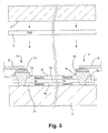
- Figs. 4-5 are cross sectional views of the product in various stages of the manufacturing process. Referring to Figs. 1-5 , an example of making a vehicle window according to an example embodiment of this invention will now be described.
- a first glass substrate 2 and a second glass substrate 4 are provided. Initially, these glass substrates 2 and 4 are flat. Then, a heatable coating 3 is deposited onto glass substrate 2 via sputtering or the like (see step S1 in Fig. 1 ).
- the heatable coating 3 is substantially transparent to visible light (e.g., has a visible transmission of at least about 50%, more preferably at least 60%, and most preferably at least about 70%).
- the heatable coating 3 consists of a transparent conductive layer of a material such as indium-tin-oxide (ITO) or silver (Ag) (e.g., see Fig. 4 embodiment).
- the heatable coating 3 may be a multi-layer coating including one or more conductive layers of ITO, Ag or the like that may be separated from one another by dielectric layer(s).
- the heatable coating 3 may be a low-E coating including one or more IR reflecting Ag inclusive layers that act as the heatable layer(s) of the coating, as described in U.S. Patent No. 6,625,875 (incorporated herein by reference).
- Fig. 5 illustrates an example embodiment where low-E heatable coating 3 includes an Ag based heatable layer 3a a provided between dielectric layers 3b and 3c.
- Edge deletion line 12 (dotted line) in Fig. 3 illustrates that the heatable coating 3 may be deleted from areas proximate the edges of the supporting substrate 2.
- first and second conductive bus bars 7 and 9 are deposited on the substrate 2 over the heatable coating 3 (see step S2 in Fig. 1 ).
- These bus bars 7 and 9 may be applied in any suitable manner, and may be provided in any suitable location on the substrate over the heatable coating 3.
- Figs. 2 and 3 illustrate two different alternative configurations for the bus bars 7 and 9.
- 7 is the top bus bar
- 9 is the bottom bus bar, and they are to be connected to respective external electrical connectors 8 at the top and bottom of the windshield respectively.
- a different bus bar configuration is provided so that the external connections to the bus bars 7 and 9 can both be made at the bottom side of the windshield.
- the bus bars 7, 9 are deposited (e.g., via silk screening or the like) directly onto and contacting the coating 3 so that the bus bars are in electrical communication with the coating 3 upon deposition.
- the coating 3 includes dielectric layer(s) over the heatable conductive layer(s)
- the bus bars as deposited are not initially in electrical communication with the conductive layer(s) of the coating; e.g., see U.S. Patent No. 6,625,875 .
- the bus bars 7, 9 may be of silver, or any other suitable conductive material in different example embodiments of this invention.
- Bus bars 7 and 9 may be thick enough so as to be opaque in certain example embodiments of this invention, although it is possible that they may be transparent.
- the glass substrate 2 with the coating 3 and bus bars 7, 9 thereon may be heat treated (e.g., thermally tempered, heat bent and/or heat strengthened) (see step S3 in Fig. 1 ).
- This heat treatment typically is at temperatures of at least 500 degrees C, more preferably at least about 600 degrees C.
- the glass substrate 2 with the coating 3 and bus bars thereon may be bent to the desired curved shape for the desired windshield application.
- This heat treatment may also cause or improve the electrical connection between the bus bars 7, 9 and the heatable layer(s) of heatable coating 3 in certain example embodiments of this invention. For instance, as described in U.S. Patent No.
- this heat treatment may cause the bus bars to flow or migrate through at least one dielectric layer(s) 3b of the coating 3 thereby creating contact hole(s) 3d and thus an electrical connection with at least one heatable conductive layer (e.g., Ag layer) 3a of the heatable coating 3. Details of this process and the electrical connections formed thereby may be found in the '875 Patent.
- the bus bars 7, 9 are in electrical contact with at least one conductive and heatable layer of the heatable coating 3.
- the top or exposed surfaces of the bus bars 7, 9 are then cleaned or burnished in order to remove any undesirable oxide layer on the top surfaces of the bus bars (see step S4 in Fig. 1 ).
- silver inclusive epoxy 15 is applied to the bus bars 7 and 9 (see step S5 in Fig. 1 ).
- the silver inclusive epoxy 15 may be a two-component silver filled epoxy designed for easy mixing and quick cure responses at room temperature.
- the two component silver filled epoxy 15 has as a first component a silver/epoxy mixture, and as a second component a hardener/silver mixture.
- Bright silver may be used in the first component and gray silver in the second component.
- the silver content of the epoxy 15 may be from about 60 to 100%, more preferably from about 65-95%, and most preferably from about 75 to 90%.
- Approximately equal amounts of the two components may be mixed together and applied to the top surface(s) of the bus bar(s) at connection area 14.
- silver epoxy 5933 or 5921 available from Applied Technologies, Exton, Pennsylvania may be used as the silver inclusive epoxy 15.
- the silver inclusive epoxy 15 has been applied to the bus bars 7, 9 at the connection areas 14, then external conductive connectors 8 are applied at the connection areas 14 over the epoxy 15 (see step S6 in Fig. 1 ).
- the epoxy 15 is sandwiched between and may contact the bus bars on one side and the connectors 8 on the other side.
- the external connectors 8 may be copper wire or copper foil/tape that is highly conductive.
- a roller or any other suitable tool may be used to flatten or roll the area where the connector 8 overlaps the epoxy 15 to make a thinner overall structure at the connection area 14 (see step S7 in Fig. 1 ).
- the epoxy 15 may begin curing, thereby resulting in the silver inclusive epoxy 15 electrically connecting bus bars 7 and 9 to the corresponding external connectors 8.
- the use of the silver inclusive epoxy permits a thin substantially uniform electrical connection to be made and permits numerous example advantages to be realized.
- the total cross-sectional thickness of the combination of the silver inclusive epoxy 15 and the external connector 8 is less than about 1 mm, more preferably less than about 0.7 mm, even more preferably from about 0.1 to 0.7 mm, still more preferably from about 0.1 to 0.6 mm, and most preferably from about 0.2 to 0.4 mm.
- a polymer inclusive laminating interlayer 5 of or including polyvinyl butyral (PVB) or any other suitable polymer based laminating material is provided over the connection area 14 and coating 3, so as to laminate glass substrates 2 and 4 to one another as shown in Fig. 5 (see step S8 in Fig. 1 ).
- the two glass substrates 2, 4 with interlayer 5 therebetween are heated to typical laminating temperature(s) in order to laminate the glass substrates to one another thereby finalizing the electrical connections between the bus bars and external connectors, and also forming the vehicle windshield or other laminated window product.
- the need for nothing the second glass substrate is avoided, and soldering for creating these electrical connections may also be avoided.
- the so-assembled vehicle window may then be installed in the vehicle as a windshield, backlite or the like.
- aforesaid embodiment discussed in connection with Figs. 1-5 describes a laminated vehicle window in which two glass substrates are laminated to one another
- this invention is not so limited.
- a single glass substrate may instead be used.
- the Fig. 4 structure may be used as a heatable window, without the need for any additional substrate or laminating layer.
- this invention is not so limited; for example a grid-type heating element including a plurality of substantially parallel wires connected to bus bars may instead be used.
Landscapes
- Surface Heating Bodies (AREA)
- Resistance Heating (AREA)
- Joining Of Glass To Other Materials (AREA)
Claims (18)
- Un procédé de fabrication d'une vitre de véhicule chauffante, le procédé comprenant :la formation d'un revêtement substantiellement transparent (3) incluant au moins une couche chauffante sur un substrat en verre (2) ;la mise en place de première et seconde barres bus conductrices (7, 9) sur le substrat en verre (2) au-dessus d'au moins le revêtement (3), d'une manière telle que les première et seconde barres bus conductrices (7, 9) soient en communication électrique avec la couche chauffante du revêtement (3) ;le raccordement électrique d'un connecteur conducteur externe (8) à l'une des barres bus (7, 9) en utilisant un époxy incorporant de l'argent (15), l'époxy incorporant de l'argent (15) étant placé entre ladite une des barres bus (7, 9) et le connecteur externe (8).
- Le procédé de la revendication 1, comprenant le raccordement électrique de premier et second connecteurs conducteurs externes (8) à la première et seconde barres bus (7, 9), respectivement, en utilisant un époxy incorporant de l'argent (15).
- Le procédé de la revendication 1, dans lequel l'époxy incorporant de l'argent (15) comprend un époxy bicomposant incorporant de l'argent.
- Le procédé de la revendication 3, dans lequel l'époxy bicomposant incorporant de l'argent (15) comprend en tant que premier composant un mélange argent/époxy, et en tant que second composant un mélange durcisseur/argent.
- Le procédé de la revendication 1, dans lequel la teneur en argent de l'époxy incorporant de l'argent (15) est comprise entre environ 60 et 100 %.
- Le procédé de la revendication 1, dans lequel la teneur en argent de l'époxy incorporant de l'argent (15) est comprise entre environ 65 et 95 %.
- Le procédé de la revendication 1, dans lequel la teneur en argent de l'époxy incorporant de l'argent (15) est comprise entre environ 75 et 90 %.
- Le procédé de la revendication 1, dans lequel dans la vitre de véhicule chauffante une épaisseur totale en section droite d'une combinaison de l'époxy incorporant de l'argent (15) et du connecteur externe (8) est inférieure à environ 1 mm.
- Le procédé de la revendication 1, dans lequel dans la vitre de véhicule chauffante une épaisseur totale en section droite d'une combinaison de l'époxy incorporant de l'argent (15) et du connecteur externe (8) est comprise entre environ 0,1 et 0,6 mm.
- Le procédé de la revendication 1, comprenant en outre le feuilletage du substrat en verre (2) avec l'époxy incorporant de l'argent (15), les barres bus (7, 9) et le revêtement (3) au-dessus, sur un autre substrat en verre (4) en utilisant au moins une intercouche incorporant un polymère (5).
- Le procédé de la revendication 1, dans lequel le revêtement (3) est formé par la couche chauffante, de sorte que les barres bus (7, 9) lorsqu'elles sont déposées viennent directement en contact avec la couche chauffante.
- Le procédé de la revendication 1, dans lequel le revêtement (3) comprend la couche chauffante prise en sandwich entre au moins les première et seconde couches diélectriques (3b, 3c), et dans lequel un traitement thermique est effectué avant l'application de l'époxy incorporant de l'argent (15) pour réaliser une trempe thermique du substrat en verre (2) et pour faire en sorte que les barres bus (7, 9) migrent ou se déplacent au travers au moins l'une des couches diélectriques (3b, 3c) et réalisent une liaison électrique avec la couche chauffante (3).
- Le procédé de la revendication 1, dans lequel la couche chauffante (3) est une couche d'argent ou d'oxyde-indium-étain.
- Une fenêtre de véhicule chauffante, comprenant :une couche chauffante (3) électriquement reliée à des première et seconde barres bus conductrices (7, 9) ; etun époxy incorporant de l'argent (15) reliant électriquement au moins l'une des barres bus conductrices (7, 9) à au moins un connecteur externe (8), l'époxy incorporant de l'argent (15) étant placé entre ladite une des barres bus (7, 9) et le connecteur externe (8).
- La vitre de véhicule chauffante de la revendication 14, dans laquelle l'époxy incorporant de l'argent (15) comprend de l'époxy et d'environ 60 à 95 % d'argent.
- La fenêtre de véhicule chauffante de la revendication 14, dans laquelle l'époxy incorporant de l'argent (15) comprend un époxy bicomposant incorporant de l'argent incluant en tant que premier composant un mélange argent/époxy et en tant que second composant un mélange durcisseur/argent.
- La fenêtre de véhicule chauffante de la revendication 14, dans laquelle dans la fenêtre de véhicule chauffante une épaisseur totale en section droite d'une combinaison de l'époxy incorporant de l'argent (15) et du connecteur externe (8) électriquement reliée à celui-ci est comprise entre environ 0,1 et 0,6 mm.
- La fenêtre de véhicule chauffante de la revendication 14, dans laquelle la fenêtre de véhicule chauffante est un pare-brise feuilleté de véhicule.
Applications Claiming Priority (2)
| Application Number | Priority Date | Filing Date | Title |
|---|---|---|---|
| US11/196,514 US8299400B2 (en) | 2005-08-04 | 2005-08-04 | Heatable vehicle window utilizing silver inclusive epoxy electrical connection and method of making same |
| PCT/US2006/027905 WO2007018984A2 (fr) | 2005-08-04 | 2006-07-18 | Fenetre de vehicule chauffable et son procede de fabrication |
Publications (3)
| Publication Number | Publication Date |
|---|---|
| EP1910123A2 EP1910123A2 (fr) | 2008-04-16 |
| EP1910123A4 EP1910123A4 (fr) | 2009-11-25 |
| EP1910123B1 true EP1910123B1 (fr) | 2015-06-17 |
Family
ID=37716723
Family Applications (1)
| Application Number | Title | Priority Date | Filing Date |
|---|---|---|---|
| EP06787756.3A Not-in-force EP1910123B1 (fr) | 2005-08-04 | 2006-07-18 | Fenetre de vehicule chauffable et son procede de fabrication |
Country Status (4)
| Country | Link |
|---|---|
| US (1) | US8299400B2 (fr) |
| EP (1) | EP1910123B1 (fr) |
| CA (1) | CA2615806A1 (fr) |
| WO (1) | WO2007018984A2 (fr) |
Families Citing this family (15)
| Publication number | Priority date | Publication date | Assignee | Title |
|---|---|---|---|---|
| US7847745B2 (en) * | 2007-11-20 | 2010-12-07 | Centre Luxembourgeois De Recherches Pour Le Verre Et La Ceramique S.A. (C.R.V.C.) | Windshield antenna and/or vehicle incorporating the same |
| DE102008018147A1 (de) * | 2008-04-10 | 2009-10-15 | Saint-Gobain Sekurit Deutschland Gmbh & Co. Kg | Transparente Scheibe mit einer beheizbaren Beschichtung und niederohmigen leitenden Strukturen |
| US8257830B2 (en) * | 2008-07-31 | 2012-09-04 | Ppg Industries Ohio, Inc. | Electrically conductive protective liner and method of manufacture |
| US7829951B2 (en) * | 2008-11-06 | 2010-11-09 | Qualcomm Incorporated | Method of fabricating a fin field effect transistor (FinFET) device |
| JP6186725B2 (ja) * | 2011-01-14 | 2017-08-30 | 旭硝子株式会社 | 車両用窓ガラスの製造方法 |
| US9309589B2 (en) | 2011-06-21 | 2016-04-12 | Ppg Industries Ohio, Inc. | Outboard durable transparent conductive coating on aircraft canopy |
| ES2596271T3 (es) * | 2012-01-20 | 2017-01-05 | Saint-Gobain Glass France | Elemento de conexión |
| CA2879446C (fr) * | 2012-08-01 | 2017-09-12 | Saint-Gobain Glass France | Vitre composite avec connexion electrique |
| US8956730B2 (en) | 2012-09-28 | 2015-02-17 | Ppg Industries Ohio, Inc. | Conductive multilayer stack, coated substrates including the same, and methods of making the same |
| US9546300B2 (en) | 2012-09-28 | 2017-01-17 | Ppg Industries Ohio, Inc. | Coating composition for coated substrates and methods of making the same |
| US9326327B2 (en) | 2013-03-15 | 2016-04-26 | Ppg Industries Ohio, Inc. | Stack including heater layer and drain layer |
| US9545042B2 (en) | 2014-03-14 | 2017-01-10 | Ppg Industries Ohio, Inc. | P-static charge drain layer including carbon nanotubes |
| US10442549B2 (en) | 2015-04-02 | 2019-10-15 | Ppg Industries Ohio, Inc. | Liner-type, antistatic topcoat system for aircraft canopies and windshields |
| US10601148B2 (en) * | 2017-10-23 | 2020-03-24 | Illinois Tool Works Inc. | High wattage solderless flexible connector for printed conductors |
| US11530478B2 (en) | 2019-03-19 | 2022-12-20 | Applied Materials, Inc. | Method for forming a hydrophobic and icephobic coating |
Family Cites Families (21)
| Publication number | Priority date | Publication date | Assignee | Title |
|---|---|---|---|---|
| US3705047A (en) * | 1969-05-23 | 1972-12-05 | Libbey Owens Ford Co | Method of repairing electrically conducting frit circuits |
| US3915833A (en) * | 1974-01-28 | 1975-10-28 | Steven A Michalek | Electrolytic cell with improved bipolar electrode connection |
| DE3344958C1 (de) * | 1983-12-13 | 1984-07-19 | VEGLA Vereinigte Glaswerke GmbH, 5100 Aachen | Verfahren zum Verloeten eines Stromanschlusselementes mit dem Stromzufuehrungsleiter einer heizbaren Glasscheibe |
| DE3512158A1 (de) * | 1985-04-03 | 1986-10-23 | W.C. Heraeus Gmbh, 6450 Hanau | Elektrisches bauelement sowie verfahren zum herstellen eines solchen bauelementes |
| US4786784A (en) | 1987-02-17 | 1988-11-22 | Libbey-Owens-Ford Co. | Method for producing an electrically heated window assembly and resulting article |
| US4755659A (en) * | 1987-02-03 | 1988-07-05 | Chomerics, Inc. | Combined busbar and electrical lead assembly |
| GB8803519D0 (en) * | 1988-02-16 | 1988-03-16 | Emi Plc Thorn | Electrical connectors |
| DE3937346A1 (de) | 1989-11-09 | 1991-05-16 | Ver Glaswerke Gmbh | Elektrisch beheizbare autoglasscheibe aus verbundglas |
| US5250228A (en) * | 1991-11-06 | 1993-10-05 | Raychem Corporation | Conductive polymer composition |
| US6213602B1 (en) | 1998-04-30 | 2001-04-10 | Ppg Industries Ohio, Inc. | Metal bus bar and tab application method |
| ATE280486T1 (de) | 2000-01-25 | 2004-11-15 | Pilkington Italia Spa | Verglasung mit elektrischem anschluss |
| US6204480B1 (en) * | 2000-02-01 | 2001-03-20 | Southwall Technologies, Inc. | Vacuum deposition of bus bars onto conductive transparent films |
| US6548175B2 (en) | 2001-01-11 | 2003-04-15 | International Business Machines Corporation | Epoxy-siloxanes based electrically conductive adhesives for semiconductor assembly and process for use thereof |
| US6602371B2 (en) | 2001-02-27 | 2003-08-05 | Guardian Industries Corp. | Method of making a curved vehicle windshield |
| US6472636B1 (en) | 2001-03-26 | 2002-10-29 | Guardian Industries Corp. | Bus bar arrangement for heatable vehicle window |
| US6625875B2 (en) * | 2001-03-26 | 2003-09-30 | Centre Luxembourgeois De Recherches Pour Le Verre Et La Ceramique S.A. (C.R.V.C.) | Method of attaching bus bars to a conductive coating for a heatable vehicle window |
| US6598426B2 (en) | 2001-04-11 | 2003-07-29 | Guardian Industries Corp. | Method of making a vehicle window with opaque layer |
| US6559419B1 (en) | 2001-08-03 | 2003-05-06 | Centre Luxembourgeois De Recherches Pour Le Verre Et La Ceramique S.A. (C.R.V.C.) | Multi-zone arrangement for heatable vehicle window |
| US6906287B2 (en) | 2001-09-06 | 2005-06-14 | Centre Luxembourgeois De Recherches Pour Le Verre Et La Ceramique S.A. (C.R.V.C.) | Connector structure for bus bars in heatable vehicle window |
| JP3849533B2 (ja) * | 2002-01-25 | 2006-11-22 | 日本板硝子株式会社 | ウインドシールド用合わせガラス |
| US6870134B2 (en) | 2002-02-01 | 2005-03-22 | Centre Luxembourgeois De Recherches Pour Le Verre Et La Ceramique S.A. (C.R.V.C.) | Heatable vehicle windshield with bus bars including braided and printed portions |
-
2005
- 2005-08-04 US US11/196,514 patent/US8299400B2/en active Active
-
2006
- 2006-07-18 WO PCT/US2006/027905 patent/WO2007018984A2/fr active Application Filing
- 2006-07-18 EP EP06787756.3A patent/EP1910123B1/fr not_active Not-in-force
- 2006-07-18 CA CA002615806A patent/CA2615806A1/fr not_active Abandoned
Also Published As
| Publication number | Publication date |
|---|---|
| EP1910123A4 (fr) | 2009-11-25 |
| WO2007018984A2 (fr) | 2007-02-15 |
| WO2007018984A3 (fr) | 2007-04-05 |
| US20070029299A1 (en) | 2007-02-08 |
| EP1910123A2 (fr) | 2008-04-16 |
| CA2615806A1 (fr) | 2007-02-15 |
| US8299400B2 (en) | 2012-10-30 |
Similar Documents
| Publication | Publication Date | Title |
|---|---|---|
| EP1910123B1 (fr) | Fenetre de vehicule chauffable et son procede de fabrication | |
| US6870134B2 (en) | Heatable vehicle windshield with bus bars including braided and printed portions | |
| KR940010815B1 (ko) | 전기적 가열가능 투명체 및 그의 제작방법 | |
| CA2537237C (fr) | Procede de brasure et compositions de brasure | |
| EP3302966B1 (fr) | Vitrage feuilleté | |
| RU2746223C2 (ru) | Стекло, оснащенное электропроводящим устройством с улучшенными зонами пайки | |
| WO2007116088A1 (fr) | Panneau de verre dote de connexions electriques soudees | |
| CN101283626A (zh) | 改善了视觉舒适度的层状加热玻璃窗 | |
| US5299726A (en) | Connection for glazings having an electroconductive layer | |
| JP7148409B2 (ja) | 加熱可能なグレイジング | |
| WO2020150324A1 (fr) | Barre omnibus conductrice pour connexion électrique sur une fenêtre de véhicule | |
| JP2023512543A (ja) | フレキシブルフラットケーブルを含む接続構造 | |
| US10286473B2 (en) | Method for producing a disk with an electrically conductive coating and a metal strip which is soldered onto the disk; and corresponding disk | |
| EP0385791B1 (fr) | Fabrication de vitres à chauffage | |
| JP2003176154A (ja) | 通電加熱ガラス | |
| EP0367209B1 (fr) | Vitre chaffante chauffée électriquement | |
| EP0385785A1 (fr) | Préparation de vitres chauffées | |
| EP4106993A1 (fr) | Procédé pour dissimuler une barre omnibus d'un vitrage feuilleté | |
| WO2024083950A1 (fr) | Vitrage |
Legal Events
| Date | Code | Title | Description |
|---|---|---|---|
| PUAI | Public reference made under article 153(3) epc to a published international application that has entered the european phase |
Free format text: ORIGINAL CODE: 0009012 |
|
| 17P | Request for examination filed |
Effective date: 20080125 |
|
| AK | Designated contracting states |
Kind code of ref document: A2 Designated state(s): AT BE BG CH CY CZ DE DK EE ES FI FR GB GR HU IE IS IT LI LT LU LV MC NL PL PT RO SE SI SK TR |
|
| A4 | Supplementary search report drawn up and despatched |
Effective date: 20091023 |
|
| 17Q | First examination report despatched |
Effective date: 20100126 |
|
| DAX | Request for extension of the european patent (deleted) | ||
| GRAP | Despatch of communication of intention to grant a patent |
Free format text: ORIGINAL CODE: EPIDOSNIGR1 |
|
| INTG | Intention to grant announced |
Effective date: 20150205 |
|
| GRAS | Grant fee paid |
Free format text: ORIGINAL CODE: EPIDOSNIGR3 |
|
| GRAA | (expected) grant |
Free format text: ORIGINAL CODE: 0009210 |
|
| AK | Designated contracting states |
Kind code of ref document: B1 Designated state(s): AT BE BG CH CY CZ DE DK EE ES FI FR GB GR HU IE IS IT LI LT LU LV MC NL PL PT RO SE SI SK TR |
|
| REG | Reference to a national code |
Ref country code: GB Ref legal event code: FG4D |
|
| REG | Reference to a national code |
Ref country code: CH Ref legal event code: EP |
|
| REG | Reference to a national code |
Ref country code: AT Ref legal event code: REF Ref document number: 731718 Country of ref document: AT Kind code of ref document: T Effective date: 20150715 |
|
| REG | Reference to a national code |
Ref country code: IE Ref legal event code: FG4D |
|
| REG | Reference to a national code |
Ref country code: DE Ref legal event code: R096 Ref document number: 602006045716 Country of ref document: DE |
|
| PG25 | Lapsed in a contracting state [announced via postgrant information from national office to epo] |
Ref country code: LT Free format text: LAPSE BECAUSE OF FAILURE TO SUBMIT A TRANSLATION OF THE DESCRIPTION OR TO PAY THE FEE WITHIN THE PRESCRIBED TIME-LIMIT Effective date: 20150617 Ref country code: FI Free format text: LAPSE BECAUSE OF FAILURE TO SUBMIT A TRANSLATION OF THE DESCRIPTION OR TO PAY THE FEE WITHIN THE PRESCRIBED TIME-LIMIT Effective date: 20150617 |
|
| REG | Reference to a national code |
Ref country code: AT Ref legal event code: MK05 Ref document number: 731718 Country of ref document: AT Kind code of ref document: T Effective date: 20150617 |
|
| REG | Reference to a national code |
Ref country code: LT Ref legal event code: MG4D Ref country code: NL Ref legal event code: MP Effective date: 20150617 |
|
| PG25 | Lapsed in a contracting state [announced via postgrant information from national office to epo] |
Ref country code: GR Free format text: LAPSE BECAUSE OF FAILURE TO SUBMIT A TRANSLATION OF THE DESCRIPTION OR TO PAY THE FEE WITHIN THE PRESCRIBED TIME-LIMIT Effective date: 20150918 Ref country code: LV Free format text: LAPSE BECAUSE OF FAILURE TO SUBMIT A TRANSLATION OF THE DESCRIPTION OR TO PAY THE FEE WITHIN THE PRESCRIBED TIME-LIMIT Effective date: 20150617 Ref country code: BG Free format text: LAPSE BECAUSE OF FAILURE TO SUBMIT A TRANSLATION OF THE DESCRIPTION OR TO PAY THE FEE WITHIN THE PRESCRIBED TIME-LIMIT Effective date: 20150917 |
|
| PG25 | Lapsed in a contracting state [announced via postgrant information from national office to epo] |
Ref country code: EE Free format text: LAPSE BECAUSE OF FAILURE TO SUBMIT A TRANSLATION OF THE DESCRIPTION OR TO PAY THE FEE WITHIN THE PRESCRIBED TIME-LIMIT Effective date: 20150617 |
|
| PG25 | Lapsed in a contracting state [announced via postgrant information from national office to epo] |
Ref country code: AT Free format text: LAPSE BECAUSE OF FAILURE TO SUBMIT A TRANSLATION OF THE DESCRIPTION OR TO PAY THE FEE WITHIN THE PRESCRIBED TIME-LIMIT Effective date: 20150617 Ref country code: SK Free format text: LAPSE BECAUSE OF FAILURE TO SUBMIT A TRANSLATION OF THE DESCRIPTION OR TO PAY THE FEE WITHIN THE PRESCRIBED TIME-LIMIT Effective date: 20150617 Ref country code: IS Free format text: LAPSE BECAUSE OF FAILURE TO SUBMIT A TRANSLATION OF THE DESCRIPTION OR TO PAY THE FEE WITHIN THE PRESCRIBED TIME-LIMIT Effective date: 20151017 Ref country code: ES Free format text: LAPSE BECAUSE OF FAILURE TO SUBMIT A TRANSLATION OF THE DESCRIPTION OR TO PAY THE FEE WITHIN THE PRESCRIBED TIME-LIMIT Effective date: 20150617 Ref country code: PT Free format text: LAPSE BECAUSE OF FAILURE TO SUBMIT A TRANSLATION OF THE DESCRIPTION OR TO PAY THE FEE WITHIN THE PRESCRIBED TIME-LIMIT Effective date: 20151019 Ref country code: CZ Free format text: LAPSE BECAUSE OF FAILURE TO SUBMIT A TRANSLATION OF THE DESCRIPTION OR TO PAY THE FEE WITHIN THE PRESCRIBED TIME-LIMIT Effective date: 20150617 Ref country code: PL Free format text: LAPSE BECAUSE OF FAILURE TO SUBMIT A TRANSLATION OF THE DESCRIPTION OR TO PAY THE FEE WITHIN THE PRESCRIBED TIME-LIMIT Effective date: 20150617 Ref country code: RO Free format text: LAPSE BECAUSE OF NON-PAYMENT OF DUE FEES Effective date: 20150617 |
|
| REG | Reference to a national code |
Ref country code: CH Ref legal event code: PL |
|
| REG | Reference to a national code |
Ref country code: DE Ref legal event code: R097 Ref document number: 602006045716 Country of ref document: DE |
|
| PG25 | Lapsed in a contracting state [announced via postgrant information from national office to epo] |
Ref country code: MC Free format text: LAPSE BECAUSE OF FAILURE TO SUBMIT A TRANSLATION OF THE DESCRIPTION OR TO PAY THE FEE WITHIN THE PRESCRIBED TIME-LIMIT Effective date: 20150617 |
|
| REG | Reference to a national code |
Ref country code: IE Ref legal event code: MM4A |
|
| PLBE | No opposition filed within time limit |
Free format text: ORIGINAL CODE: 0009261 |
|
| STAA | Information on the status of an ep patent application or granted ep patent |
Free format text: STATUS: NO OPPOSITION FILED WITHIN TIME LIMIT |
|
| PG25 | Lapsed in a contracting state [announced via postgrant information from national office to epo] |
Ref country code: IT Free format text: LAPSE BECAUSE OF FAILURE TO SUBMIT A TRANSLATION OF THE DESCRIPTION OR TO PAY THE FEE WITHIN THE PRESCRIBED TIME-LIMIT Effective date: 20150617 Ref country code: DK Free format text: LAPSE BECAUSE OF FAILURE TO SUBMIT A TRANSLATION OF THE DESCRIPTION OR TO PAY THE FEE WITHIN THE PRESCRIBED TIME-LIMIT Effective date: 20150617 Ref country code: LI Free format text: LAPSE BECAUSE OF NON-PAYMENT OF DUE FEES Effective date: 20150731 Ref country code: CH Free format text: LAPSE BECAUSE OF NON-PAYMENT OF DUE FEES Effective date: 20150731 |
|
| REG | Reference to a national code |
Ref country code: FR Ref legal event code: ST Effective date: 20160331 |
|
| 26N | No opposition filed |
Effective date: 20160318 |
|
| GBPC | Gb: european patent ceased through non-payment of renewal fee |
Effective date: 20150917 |
|
| PG25 | Lapsed in a contracting state [announced via postgrant information from national office to epo] |
Ref country code: FR Free format text: LAPSE BECAUSE OF NON-PAYMENT OF DUE FEES Effective date: 20150817 |
|
| PG25 | Lapsed in a contracting state [announced via postgrant information from national office to epo] |
Ref country code: IE Free format text: LAPSE BECAUSE OF NON-PAYMENT OF DUE FEES Effective date: 20150718 Ref country code: GB Free format text: LAPSE BECAUSE OF NON-PAYMENT OF DUE FEES Effective date: 20150917 |
|
| PG25 | Lapsed in a contracting state [announced via postgrant information from national office to epo] |
Ref country code: SI Free format text: LAPSE BECAUSE OF FAILURE TO SUBMIT A TRANSLATION OF THE DESCRIPTION OR TO PAY THE FEE WITHIN THE PRESCRIBED TIME-LIMIT Effective date: 20150617 |
|
| PG25 | Lapsed in a contracting state [announced via postgrant information from national office to epo] |
Ref country code: BE Free format text: LAPSE BECAUSE OF FAILURE TO SUBMIT A TRANSLATION OF THE DESCRIPTION OR TO PAY THE FEE WITHIN THE PRESCRIBED TIME-LIMIT Effective date: 20150617 |
|
| PG25 | Lapsed in a contracting state [announced via postgrant information from national office to epo] |
Ref country code: HU Free format text: LAPSE BECAUSE OF FAILURE TO SUBMIT A TRANSLATION OF THE DESCRIPTION OR TO PAY THE FEE WITHIN THE PRESCRIBED TIME-LIMIT; INVALID AB INITIO Effective date: 20060718 |
|
| PG25 | Lapsed in a contracting state [announced via postgrant information from national office to epo] |
Ref country code: SE Free format text: LAPSE BECAUSE OF FAILURE TO SUBMIT A TRANSLATION OF THE DESCRIPTION OR TO PAY THE FEE WITHIN THE PRESCRIBED TIME-LIMIT Effective date: 20150617 Ref country code: CY Free format text: LAPSE BECAUSE OF FAILURE TO SUBMIT A TRANSLATION OF THE DESCRIPTION OR TO PAY THE FEE WITHIN THE PRESCRIBED TIME-LIMIT Effective date: 20150617 Ref country code: NL Free format text: LAPSE BECAUSE OF FAILURE TO SUBMIT A TRANSLATION OF THE DESCRIPTION OR TO PAY THE FEE WITHIN THE PRESCRIBED TIME-LIMIT Effective date: 20150617 |
|
| PG25 | Lapsed in a contracting state [announced via postgrant information from national office to epo] |
Ref country code: TR Free format text: LAPSE BECAUSE OF FAILURE TO SUBMIT A TRANSLATION OF THE DESCRIPTION OR TO PAY THE FEE WITHIN THE PRESCRIBED TIME-LIMIT Effective date: 20150617 |
|
| PGFP | Annual fee paid to national office [announced via postgrant information from national office to epo] |
Ref country code: DE Payment date: 20170711 Year of fee payment: 12 |
|
| PG25 | Lapsed in a contracting state [announced via postgrant information from national office to epo] |
Ref country code: LU Free format text: LAPSE BECAUSE OF NON-PAYMENT OF DUE FEES Effective date: 20150718 |
|
| REG | Reference to a national code |
Ref country code: DE Ref legal event code: R119 Ref document number: 602006045716 Country of ref document: DE |
|
| PG25 | Lapsed in a contracting state [announced via postgrant information from national office to epo] |
Ref country code: DE Free format text: LAPSE BECAUSE OF NON-PAYMENT OF DUE FEES Effective date: 20190201 |