EP1909035B1 - Oven door assembly with locking element - Google Patents
Oven door assembly with locking element Download PDFInfo
- Publication number
- EP1909035B1 EP1909035B1 EP07117994A EP07117994A EP1909035B1 EP 1909035 B1 EP1909035 B1 EP 1909035B1 EP 07117994 A EP07117994 A EP 07117994A EP 07117994 A EP07117994 A EP 07117994A EP 1909035 B1 EP1909035 B1 EP 1909035B1
- Authority
- EP
- European Patent Office
- Prior art keywords
- door
- air
- oven
- air flow
- flow
- Prior art date
- Legal status (The legal status is an assumption and is not a legal conclusion. Google has not performed a legal analysis and makes no representation as to the accuracy of the status listed.)
- Active
Links
- 238000010411 cooking Methods 0.000 claims description 101
- 238000009423 ventilation Methods 0.000 description 147
- 238000001816 cooling Methods 0.000 description 20
- 238000007664 blowing Methods 0.000 description 15
- 239000011521 glass Substances 0.000 description 13
- 238000005034 decoration Methods 0.000 description 9
- 238000004140 cleaning Methods 0.000 description 7
- 230000000694 effects Effects 0.000 description 7
- 238000010438 heat treatment Methods 0.000 description 4
- 235000015243 ice cream Nutrition 0.000 description 4
- 238000000197 pyrolysis Methods 0.000 description 4
- 238000010276 construction Methods 0.000 description 3
- 239000002184 metal Substances 0.000 description 3
- 239000000203 mixture Substances 0.000 description 3
- 238000004026 adhesive bonding Methods 0.000 description 2
- 238000005273 aeration Methods 0.000 description 2
- 230000005465 channeling Effects 0.000 description 2
- 230000003247 decreasing effect Effects 0.000 description 2
- 238000009413 insulation Methods 0.000 description 2
- 230000006978 adaptation Effects 0.000 description 1
- 238000009826 distribution Methods 0.000 description 1
- 230000007257 malfunction Effects 0.000 description 1
- 238000004519 manufacturing process Methods 0.000 description 1
- 238000000034 method Methods 0.000 description 1
- 238000012986 modification Methods 0.000 description 1
- 230000004048 modification Effects 0.000 description 1
- 210000000056 organ Anatomy 0.000 description 1
- 238000013021 overheating Methods 0.000 description 1
- 239000004033 plastic Substances 0.000 description 1
- 230000001737 promoting effect Effects 0.000 description 1
- 230000000284 resting effect Effects 0.000 description 1
- 125000006850 spacer group Chemical group 0.000 description 1
- 229910001220 stainless steel Inorganic materials 0.000 description 1
- 239000010935 stainless steel Substances 0.000 description 1
- 239000012815 thermoplastic material Substances 0.000 description 1
- 238000012800 visualization Methods 0.000 description 1
Images


Classifications
-
- F—MECHANICAL ENGINEERING; LIGHTING; HEATING; WEAPONS; BLASTING
- F24—HEATING; RANGES; VENTILATING
- F24C—DOMESTIC STOVES OR RANGES ; DETAILS OF DOMESTIC STOVES OR RANGES, OF GENERAL APPLICATION
- F24C15/00—Details
- F24C15/02—Doors specially adapted for stoves or ranges
- F24C15/04—Doors specially adapted for stoves or ranges with transparent panels
-
- F—MECHANICAL ENGINEERING; LIGHTING; HEATING; WEAPONS; BLASTING
- F24—HEATING; RANGES; VENTILATING
- F24C—DOMESTIC STOVES OR RANGES ; DETAILS OF DOMESTIC STOVES OR RANGES, OF GENERAL APPLICATION
- F24C15/00—Details
- F24C15/006—Arrangements for circulation of cooling air
-
- F—MECHANICAL ENGINEERING; LIGHTING; HEATING; WEAPONS; BLASTING
- F24—HEATING; RANGES; VENTILATING
- F24C—DOMESTIC STOVES OR RANGES ; DETAILS OF DOMESTIC STOVES OR RANGES, OF GENERAL APPLICATION
- F24C15/00—Details
- F24C15/02—Doors specially adapted for stoves or ranges
Definitions
- the present invention relates to the assembly of a baking oven door.
- It also relates to a cooking oven equipped with means for assembling the door also for locking said door during a cooking operation or during a cleaning operation.
- the present invention relates to domestic cooking ovens in which a locking device of a door must be implemented to ensure the safety of the oven door and the user during a cooking operation or cleaning while simplifying the construction of said door.
- the present invention relates to an element of at least one means for locking a door intended to equip a cooking oven.
- This oven can be pyrolyzed, in which the temperature inside the cooking chamber can reach 500 ° C during pyrolysis cycles.
- the present invention relates to baking ovens comprising a muffle surrounded by a housing comprising an upper wall, side walls and a bottom wall, and the front face of the muffle is closed by a door.
- a cooking door generally comprises an inner ice intended to close the cooking chamber, an outer ice-cream, visible on the facade of the cooking appliance and one or more intermediate ice-creams arranged in a door frame between the ice-cream outside and the inner ice.
- the intermediate windows allow, by creating insulating air slats, and through ventilation creating cooling air flows circulating between the different windows of the door, to limit the temperature rise of the door, especially at the level of the outer ice.
- Cooking ovens comprising a door provided with a door frame, an inner window, an outer window, one or more intermediate windows, and means for fixing and assembling said windows.
- the outer glass is assembled on the door frame by means of a cross member and fixing screws. Said crossbar also allows to fix by screwing a handle for opening and closing door.
- the inner ice is generally assembled in the door frame by fastening means by screwing or by gluing.
- the intermediate ice is mounted between the inner ice and the outer ice by means of spacers.
- these baking ovens have the disadvantage of using additional means to allow the locking of the door with the structure of the oven. These additional means of locking the door do not participate in the assembly of the door. Therefore, the door is made up of a larger number of pieces and the number of operations to be performed during the assembly of the door is increased. These door constructions increase the cost of obtaining a baking oven door.
- said additional means of locking the door are not part of the functional chain of the assembly of the door.
- EP-A2-0 953 807 which describes a cooking oven door.
- the document EP-A2-0 953 807 describes a door with a frame and a domed front window.
- the front window is mounted on the frame with one or more adapters.
- the adapter or adapters closing the space between the frame and the front window.
- the present invention aims to solve the aforementioned drawbacks and to provide a baking oven door provided with at least one element of at least one door locking means for assembling the door simply and at the lowest cost guaranteeing the safety lock of the oven door. Said at least one element of at least one locking means of the door also ensures the safety of the user when using the oven.
- the present invention is directed to a baking oven door comprising at least one inner and one outer glass mounted on a door frame, the outer glass being assembled with a cross member, said cross member being positioned in abutment with a side wall of the door frame.
- said cross member is fixed with the door frame by at least one element of at least one locking means of the door.
- the assembly of the door is fast and simple by minimizing the number of elements constituting said door.
- the locking of the door can be achieved by said at least one element of at least one locking means for all the oven models.
- Said at least one element of at least one locking means of the door constitutes a means for assembling the door and also a means for locking the door. In this way, the fastening means required for the assembly of the door are simplified and minimized, hence the cost of obtaining the optimized door.
- Said at least one element of at least one locking means of the door can also be used to detect the contact of the door with the front face of the oven to turn on or off a lamp placed inside the door or in a wall of the cooking chamber.
- said at least one element of at least one locking means of the door for the assembly of the door ensures a precise positioning with respect to the various elements constituting said at least one locking means. In this way, the door lock is guaranteed for every use of the oven safely for the user.
- Said at least one element of at least one locking means of the door is part of the functional chain of the door assembly and thus reduces the functional clearance tolerances between the elements constituting the door.
- Said at least one element of at least one locking means of the door makes it possible to fix the door frame and the transom and to block the door of the cooking oven in the closed position.
- the cost of obtaining the baking oven is minimized and the oven door can be locked for each use where the temperature detected by a temperature measuring means exceeds a predetermined threshold.
- said at least one element of at least one locking means comprises resilient snap-fastening means.
- the assembly of the at least one element of at least one locking means of the cross member on the door frame can allow easy and quick assembly and disassembly of the door to allow the change of a component constituting the door. during an intervention of the after-sales service.
- the aesthetics of the door of the baking oven is improved by not revealing means of attachment visible to the user.
- said at least one element of at least one locking of the door is a lock strike of the door.
- the locking of the door can be easily implemented with at least one conventional locking means.
- the use of at least one conventional locking means makes it possible to minimize the cost of obtaining the oven.
- said at least one element of at least one locking means comprises at least one housing cooperating with a finger of a lock assembled on the oven.
- said at least one locking means comprises a bolt fitting into at least one housing of said at least one locking striker.
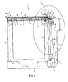
- a baking oven 1 comprises a muffle 2 whose front face 3 is closed by a door 4, and surrounded by a housing 5 comprising an upper wall 6, side walls 7 and a bottom wall 8.
- the baking oven 1 may comprise a ventilation device 10 having a fan 11 connected to at least one ventilation duct 12 placed in a space 13 between the casing 5 and the muffle 2 and intended to create an air flow between openings input 15 and output 14.
- the ventilation device 10 comprises at least one suction channel 16, at least one discharge channel 12 and a fan 11.
- the suction channel 16 has at least one inlet opening 17 front face 3 of the baking oven 1 and at least one outlet opening 18 in a suction zone of the fan 11.
- Said at least one inlet opening 17 of the suction channel 16 on the front face 3 of the oven 1 is connected to at least one outlet opening 19 formed in the door 4.
- the discharge channel 12 comprises at least one inlet opening 20 in a blow zone of the fan 11 and at least one outlet opening 14 on the front face 3 of the cooking oven 1 to expel the air towards the outside of the oven 1.
- this door 4 for cooking chamber 2 can equip a domestic cooking oven 1, and for example an electric cooking oven adapted to implement a pyrolysis cycle for cleaning the cooking chamber 2.
- the temperature inside the cooking chamber 2 can reach 500 ° C.
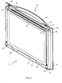
- FIG. figure 2 An embodiment of a door 4 for a cooking chamber 2 is illustrated in FIG. figure 2 .
- the door 4 includes an outer window 21 intended to come to the front of the device.
- This outer glaze 21 generally forms a decoration and consists of a transparent surface on its entire surface or at least a major part of its surface to allow viewing of the inside of the cooking chamber 2.
- the outer ice 21 may be ornamented with a decorative facade 22, for example stainless steel.
- This outer window 21 is associated with a door frame 23.
- This door frame 23 is integrally mounted on the outer window 21 by means of a fastening element 24 and various fixing elements of the fixing screw type. which are not described here in detail.
- the door frame 23 is rectangular and is intended to house an inner window 25.
- This inner window 25 is removably mounted in the door frame 23 as will be described later.
- This inner ice 25 is intended to come opposite the cooking chamber 2 and to close an opening 26 thereof.
- two intermediate windows 27 and 28 are arranged in the door frame 23.
- the windows 25, 27 and 28 comprise transparent surfaces allowing the user to observe through the door 4 the contents of the cooking chamber 2.
- the windows 25, 27 and 28 are made of transparent surfaces.
- the intermediate windows 27 and 28 are mounted in the door frame 23 through to holding means 29.
- the outer window 21 is arranged to receive a door handle 30 fixed by bearing on the outer surface 31 of said outer window 21 by known means, such as for example by screwing.
- Said handle 30 can be screwed into a fastener 24 of the handle 30 generally metal.
- Said handle 30 may comprise a bar 32 to allow the opening and closing of said door 30 and at least two bases 33 which are fixed on the fixing element 24 and resting on the outer window 21.
- the inner window 25 facing the opening 26 of the cooking chamber 2 is fixed to the door frame 23 by resilient snap-fastening means 34 or else by means of assembly by gluing.
- the inner lens 21 can be removably mounted and inserted into a groove 35 formed by the door frame 23.
- the door frame 23 further comprises at least one recess 36 forming a gripping space at the edge of the intermediate windows 27 and 28.
- This recess 36 allows the user to move the hand to lift the intermediate windows 27 and 28 during disassembly of these windows 27 and 28.
- a ventilation device 10 adapted to suck and / or blow air through the door 4 by a direct suction or an effect Venturi, between the various mirrors 21, 25, 27 and 28.
- the door frame 23 comprises slots 37 at respectively the upper edge 38 and the lower edge 39 of the door 4.
- the door 4 comprises at least three windows 21, 25 and 27 parallel to each other and spaced so as to form two air passages for the flow of an air flow.
- the door 4 may comprise four windows 21, 25, 27 and 28, two intermediate windows 27 and 28 spaced so as to form three blades. 40, 41 and 42, the central air blade 41 allows the flow of an air flow represented by the arrows P, as illustrated in FIG. figure 1 .
- the two air knives 40 and 42 placed between the intermediate windows 27 and 28 and said inner 25 and outer 21 window can allow the flow or not of a flow of air.
- the door 4 also includes two hinges 43 for connecting to the front 44 of the appliance 1. These hinges 43 consist of a metal body, a spring and an arm.
- Said two hinges 43 allow the opening and closing of the door 4.
- These hinges 43 consist of a metal body, inside the body of the hinge 43 is placed a spring. These hinges 43 make it possible to keep the door 4 in the closed position and in the open position, in particular to introduce or remove a dish from the cooking chamber 2, and to hold the door 4 in an equilibrium position between the open position and the closed position. .
- the hinges 43 are connected on the one hand to the door 4 and on the other hand to the front face 3 of a furnace 1 by an arm.
- a door 4 of a baking oven 1 comprises at least one inner ice 25 and one outer ice-cream 21 mounted on a door frame 23.
- the outer window 21 is assembled with a crossmember 46, said crossmember 46 being positioned in abutment with a side wall 38 of the door frame 23, and said crossmember 46 being fixed with the door frame 23 by at least one element 45 of less a locking means (not shown) of the door 4.
- the assembly of the door 4 is fast and simple by minimizing the number of elements constituting said door 4.
- the locking of the door 4 can be achieved by said at least one element 45 of at least one locking means for all of the cooking oven models 1.
- Said at least one element 45 of at least one locking means of the door 4 constitutes a means for assembling the door 4 and also a means of locking the door 4. In this way, the fastening means necessary for the assembly of the door 4 are simplified and minimized, hence the cost of obtaining the optimized door 4.
- Said at least one element 45 of at least one locking means of the door 4 can also serve to detect the contact of the door 4 with the front face 3 of the oven 1 to turn on or off a lamp (not shown) placed at the door. inside the door 4 or in a wall of the cooking chamber 2.
- said at least one element 45 of at least one locking means of the door 4 ensures a precise positioning with respect to the different elements constituting said at least one locking means. In this way, the locking of the door 4 is guaranteed for each use of the oven 1 safely for the user.
- Said at least one element 45 of at least one locking means of the door 4 is part of the functional chain of the assembly of the door 4 and thus reduces the functional clearance tolerances between the elements constituting the door 4.
- Said at least one element 45 of at least one locking means of the door 4 allows to fix the door frame 23 and the crossmember 46 and to block in the closed position the door 4 of the cooking oven 1.
- the cost of obtaining the baking oven 1 is minimized and the door 4 of the oven 1 can be blocked for each use where the temperature detected by a temperature measuring means (not shown) exceeds a predetermined threshold.
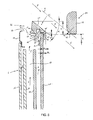
- the door 4 is assembled by forming subassemblies in order to reduce the number of assembly operations and to reduce the assembly time as illustrated in FIG. figure 5 .
- the door frame 23 is assembled with at least one hinge 43 and an inner window 25 to form a counter-door subassembly 49.
- the outer window 21 is assembled with a fastening element 24 and a door handle 30 by screwing means 50, also with the crossmember 46 being fixed on the fastening element 24 to form a door decoration subassembly 51. .
- the counter-door subassembly 49 and the door decoration subassembly 51 are assembled by said at least one element 45 of at least one locking means of the door 4.
- the door decoration subassembly 51 can thus be personalized by maintaining a counter-door subassembly 49 identical to all the cooking oven models 1.
- the door decoration sub-assembly 51 can make it possible to mounting a handle 30, a cross member 46 and an outer mirror 21 customized to each model of the baking oven 1.
- the method of assembling the counter-door subassembly 49 and the door decoration subassembly 51 is identical to each model by said at least one element 45 of at least one locking means of the door 4.
- the crossmember 46 can be adapted according to the ventilation device of the cooking oven 1.
- the crossmember 46 can make it possible to modify the outlet of an air flow F on the front face 3 of a cooking oven 1.
- said at least one element 45 of at least one locking means comprises fastening means 47 by elastic latching.
- the assembly of the at least one element 45 of at least one locking means of the crossmember 46 on the door frame 23 can allow easy and fast assembly and disassembly of the door 4 to allow the change of a door. element constituting the door 4 during an intervention of the after-sales service.
- the assembly time of the door 4 is reduced by using fastening means 47 by resilient latching.
- the cost of obtaining the door 4 is also minimized by such fastening means 47.
- the aesthetics of the door 4 of the baking oven 1 is improved by not leaving no appearing means 47 visible to the user.
- the door frame 23 comprises at least one opening 52 cooperating with at least one opening 53 in the crossmember 46 to allow their attachment by fastening means 47 by resilient snapping of said at least one element 45 of at least one locking means of the door 4.
- Said at least one aperture 52 and 53 of the door frame 23 and the cross member 46 ensure a precise assembly.
- the functional chain of the assembly is mainly provided by said at least one aperture 52 and 53 for the positioning of said at least one element 45 of at least one locking means of the door 4.
- the assembly of the door 4 and particular of the crosspiece 46 and the door frame 23 by said at least one element 45 of at least one locking means is made with a minimum clearance and a low value.
- said at least one element 45 of at least one locking means of the door 4 is placed precisely to cooperate with said at least one locking means.
- the locking of the door 4 in the closed position is thus guaranteed by the positioning of said at least one element 45 of at least one locking means of the door 4.
- said at least one element 45 of at least one locking of the door 4 is a door lock striker 4.
- the locking of the door 4 can be easily implemented with at least one conventional locking means.
- the use of at least one conventional locking means makes it possible to minimize the cost of obtaining the oven 1.
- the crosspiece 46 is fixed with the door frame 23 by two locking strikes 45 of the door 4.
- the door frame 23 is fixed rigidly with the crossmember 26 by the two latching strikes 45 of the door 4.
- said at least one locking means can be disposed on either side of the vertical median plane passing through the cooking oven 1, or two locking means can be used to lock the door 4 in the closed position.
- the crossmember 46 is placed on an inner surface of a side wall 38 of the door frame 23.
- Said at least one element 45 of at least one locking of the door 4 is a plastic part resistant to temperature during a cooking operation or during a pyrolysis cleaning operation.
- said at least one element 45 of at least one locking means comprises at least one housing 48 cooperating with a finger of a lock assembled on the furnace 1.
- said at least one locking means comprises a bolt fitting into at least one housing 48 of said at least one locking striker 45.
- the door 4 of the baking oven 1 comprises at least one intermediate ice 27 or 28 placed between the inner ice 25 and the outer ice 21.
- the door 4 of the baking oven 1 can be designed to withstand the temperature of 500 ° C inside the cooking chamber 2 during a pyrolysis cleaning mode.
- Said at least one intermediate ice 27 or 28 can be assembled with holding elements 29.
- the holding elements 29 are mounted in the corners of said at least one intermediate ice 27 or 28.
- the holding elements 29 in this embodiment are four in number and intended to be housed at the four corners of the door frame 23. They are thus mounted at the four corners of said at least one intermediate ice 27 or 28.
- the door frame 23 has four stamped shaped angles 54, as illustrated in FIG. figure 2 , adapted to respectively accommodate each retaining element 29 in the form of a wedge.
- the inner window 25 comprises at least one resilient snap-fastening means 34 cooperating with the door frame 23.
- the inner ice 25 is removable and can allow its removal to allow the cleaning of at least one intermediate ice 27 or 28 of the door 4.
- Said at least one intermediate ice 27 or 28 is also removable from the door 4 by removing the holding elements 29 of the door frame 23. In this way, each window 21, 25, 27 and 28 of the door 4 can be cleaned separately.
- the device for channeling an air flow F of constant section at the outlet of at least one ventilation channel 12 makes it possible to improve the cooling of the door 4 and the structure of the cooking oven 1.
- a height H of the passage section of an air flow F is constant over at least part of a blowing zone 73 of said at least one ventilation channel 12 and an air deflection zone 72.
- the air flow F is channeled into a section of constant height H in at least a part of a blowing zone 73 of said at least one ventilation channel 12 and in an air deflection zone 72 to avoid the looping of the air in the ventilation device 10 and in the door 4 of the oven 1 .
- the flow of air F passing through the air deflection zone 72 is directed towards the outside of the cooking oven 1 without the latter being able to return to the at least one ventilation channel 12 and consequently reducing the performance of the ventilation device. ventilation 10.
- the air flow F is remote from the door 4 of the oven 1 to avoid sucking air from the ventilation device 10 by said at least one opening 58 formed in the lower part of the door 4.
- the flow of air F leaving the air deflection zone 72 is little or not turbulent and oriented in a determined direction does not cause a return of hot air in the fresh air inlet openings of the cooking oven 1.
- the air flow F is channeled so as not to come into contact with the door handle 4 or any other decorative element of the oven 1 to avoid creating turbulence at the outlet of said air.
- the invention improves the reliability of the cooking oven 1 and ensure the safety of the user by avoiding overheating of a component constituting the baking oven 1.
- the constant height section H in at least a part of a blow zone 73 of said at least one ventilation channel 12 and in an air deflection zone 72 makes it possible to avoid creating turbulences for the air flow. F within said section.
- the constant height section H in at least a portion of a blow zone 73 of said at least one ventilation channel 12 is preferably between one third and one fifth of the length of said at least one ventilation channel 12.
- the air deflection zone 72 is constituted by a parallel upper wall 74 and a bottom wall 61 for determining the constant height H of the passage section of the air flow F above the door 4 of said furnace 1.
- the air deflection zone 73 is constituted by at least one crossmember 46 positioned below said at least one ventilation channel 12 and by at least one air deflector 60.
- the flow of air F can be oriented in a desired direction depending on the position of the door handle 4 and said at least one ventilation channel 12 opening on the front face of the oven.
- the air deflector 60 can be hidden to contribute to the aesthetics of the baking oven 1. Only the portion of the air deflector 60 serving to give a direction to the air flow F can be visible to the user. This part of the air deflector 60 can make it possible to prevent visualization of the inside of the at least one ventilation duct 12.
- Said at least one air deflector 60 is positioned at least partly within said at least one ventilation channel 12.
- the air deflector 60 may also make it possible to maintain the spacing between the upper and lower walls 78 of said at least one ventilation channel 12 of said at least part of a blowing zone 73 where the height H is constant.
- the flow of air F is directed below a door handle 4 by the air deflection zone 72 formed at one end of a blowing zone 73 of the at least one ventilation channel 12.
- the air deflection zone 72 consisting of the crossmember 46 and the air deflector 60, makes it possible to prevent the user from seeing the at least one ventilation channel 12 opening on the end face 3 of the oven 1.
- the aesthetics of the baking oven 1 is improved by positioning the door handle 30 opposite at least one opening 14 formed on the front face 3 of the oven 1 for the discharge of air by said at least one ventilation channel 12.
- the rear wall 62 of the handle 30 is cooled by the air flow F and allows the user not to burn by manipulating the handle 30 to open or close the door 4 of the cooking chamber 2.
- At least a portion of the rear wall 62 of the handle 30 may constitute an extension of the air deflection zone 72.
- the height H of the passage section of the air flow F extends in a range between 10mm and 25mm, and preferably of the order of 20mm.
- the flow rate of the air flow F of the ventilation device 10 through said at least one ventilation channel 12 makes it possible to ensure the cooling of the elements constituting the cooking oven 1.
- the speed of the air flow F can thus be adapted so as not to cause discomfort to the user and to limit the level of noise produced by the baking oven 1.
- the fan 11 for cooling the oven 1 is sized according to the constant height H of the passage section an air flow F in at least a part of a blow zone 73 of said at least one ventilation channel 12 and in an air deflection zone 72.
- Said at least one air deflector 60 comprises an inclined wall 74 and parallel to an inclined wall 61 of the crossmember 46 for directing the flow of air F towards the outside of the furnace 1 and away from the outer glazing 21.
- the air deflection zone 72 constituted by the air deflector 60 and the crossmember 46 makes it possible to prevent the flow of air F from being closed by at least one opening 15 formed in the lower part of the furnace 1 or in at least one opening 58 formed in the lower part of the door 4.
- the air discharged to the outside of the furnace 1 by the ventilation device 10 through said at least one ventilation channel 12 makes it possible to orient the air flow F in an inclined direction preventing the user from being inconvenienced. receiving a flow of hot air.
- the cross member 46 of the air deflection zone 72 may have the characteristics similar to the air deflector 55 which will be described later.
- the inclination ⁇ of the inclined wall of said at least one air deflector 60 is in a range extending between 20 ° and 50 °, and preferably of the order of 40 °.
- the flow of air F opening on the front face 3 of the oven 1 by said at least one ventilation channel 12 does not cause any inconvenience to the user receiving a hot air flow in the face or on the upper part of the body.
- the air flow F is directed towards the outside of the oven 1 without being sucked by at least one opening 15 or 58 formed in the lower part of the furnace 1.
- Said at least one opening 15 formed in the front face 3 of the oven 1 to cool the structure by leaving an air passage 64 below the furnace 1 and said at least one opening 58 in the lower part of the door 4 are remote from the air flow F to avoid a loop of air and cause too much heating of the elements constituting the oven 1.
- the air flow F is oriented so as to be remote from the outer window 21 of the door 4.
- the width D of the inclined wall 74 of said at least one air deflector 60, illustrated in FIG. figure 9 is substantially equal to the width L of the inclined wall 61 of the crosspiece 46.
- the air deflection zone 72 is of constant section and keeps the speed of the air flow F.
- the air flow F does not undergo a divergence or convergence that could increase the noise level during the delivery of air to the outside of the oven 1.
- the air flow F can not create turbulence which has the effect of reducing the efficiency of the ventilation device 10 of the oven 1 and to create disturbances at the level of said at least one an air outlet opening 14 formed in the front face 3 of the oven 1.
- the width N of the passage section of the air flow F of said at least part of a blowing zone 73 of said at least one ventilation channel 12, illustrated in FIG. figure 9 is less than or equal to the width D of the passage section of the air flow F of the air deflection zone 72.
- the width N of the passage section of the air flow F of said at least part of a blow zone 73 of said at least one ventilation channel 12 is dimensioned so as to take account of the pressure losses of said at least a ventilation channel 12. With a width N of said at least a portion of a blow zone 73 of said at least one ventilation channel 12 smaller than the width of the passage section of the air flow F of the zone of air deflection 72 allows, during the flow of air in this zone, to maintain an air flow rate F constant or at least sufficient to cool the elements constituting the oven 1.
- Said at least a portion of a blow zone 73 of said at least one ventilation channel 12 and the air deflection zone 72 are contiguous.
- the air flow F is not disturbed by at least one opening creating a turbulence and changing the orientation of said air flow F.
- the air flow F flows along a smooth wall and homogeneous so as to avoid disturbances and causing a decrease in the efficiency of the ventilation device 10 of the cooking oven 1.
- the passage section of an air flow F is constant over at least part of a blowing zone 73 of said at least one ventilation channel 12 and over a deflection zone 72.
- the air flow F circulates in a space of constant section to avoid airflow disturbances.
- the speed of the air flow F is thus constant and makes it possible to optimize the cooling performance of the cooking oven 1.
- the air deflection device 55 of the door 4 consists of at least one crossmember 46 comprising at least side walls 56 and at least one upper wall 57.
- Said air deflection device 55 of the door 4 consists of at least one crosspiece 46 made of thermoplastic material situated in the upper part of the door 4 and extending over the entire width of the door frame 23.
- This air deflection device 55 of the door 4 is assembled to react elastically against the door frame 23, to absorb the deformations experienced by the windows 21, 25, 27 and 28 constituting the door 4 during operation of the oven cooking 1.
- the air deflection device 55 and the transom 46 described previously can to be a unique piece as represented on the Figures 1 to 8 .
- the first air flow P enters at least one lower air intake passage 58 at the bottom of the door 4 of the cooking oven 1 and exits through at least one upper air outlet passage located in the top of the door 4 and is directed through at least one air inlet opening located at the rear of the air deflector 55, the air outlet area of the air flow F in the upper part of the door 4 is represented by the reference 59.
- the air deflection device 55 makes it possible to create a door 4 ventilated by the passage of a flow of air P between the inner ice 25 and the outer ice 21.
- the air sucked into the suction ventilation channel 16 is mixed in the fan 11 with air coming from the outside through at least one opening 15 formed in the upper or lower part of the cooking oven 1 and said outside air having circulated between the housing 5 and the cooking chamber 2.
- the air mixture is rejected in a discharge ventilation duct 12 towards the front face 3 of the cooking oven 1 to exit through at least one opening 14.
- the cooking oven 1 comprises a cooking chamber 2 having an opening 26 on the front face 3 closed by a door 4. Said cooking chamber 2 is surrounded by a housing 5 and said cooking oven 1 also comprises a ventilation device 10 provided at least one ventilation channel 12 placed between the cooking chamber 2 and the housing 5.
- Said at least one ventilation channel 12 opens at least on the front face 3 of said furnace 1.
- the door 4 is provided with at least one inner window 25 vis-à-vis the opening 26 of the cooking chamber 2 and an outer window 21 positioned towards the outside of said oven 1.
- the air deflection device 55 illustrated in FIGS. figures 7 and 8 , comprises at least one inclined wall 61 for directing an air flow F exiting from said at least one ventilation channel 12 on the front face 3 of the oven 1 towards the outside of said oven 1, and said at least one inclined wall 61 of said device air deflection 55 extends beyond the outer ice 21 of the door 4 to maintain the orientation of the air flow F.
- the air deflection device 55 makes it possible to improve the cooling of the upper part of the door 4 and in particular of the surface of the outer window 21 situated opposite the door handle 30.
- the air deflection device 55 also allows the rear of the door handle 4 to be cooled to prevent the user from being burned during the manipulation of the door. door 4 of oven 1.
- the air deflection device 55 of the door 4 makes it possible to avoid the looping inside the door 4 of the air expelled on the front face 3 towards the outside of the oven 1. In this way, the air sucked into the lower part of the door 4 is fresh and unheated by the operation of the baking oven 1. Therefore, the cooling of the baking oven 1 and in particular of the structure, the components and the door 4 is improved.
- the air deflection device 55 directs the air flow F in an inclined direction and away from the outer window 21 of the door 4.
- the air discharged to the outside of the furnace 1 by the ventilation device 10 is oriented in an inclined direction preventing annoyance to the user receiving a flow of hot air.
- the air deflection device 55 also makes it possible to prevent the user from seeing the at least one ventilation channel 12 opening on the front face 3 of the oven 1 so as to improve the appearance of the cooking oven 1 by positioning the oven.
- the door 4 of the baking oven 1 comprises a handle 30, said handle 30 comprising at least a portion of a rear wall 62 adapted to cooperate with the air deflection device 55 to guide the flow of air F.
- the air flow F is oriented in an inclined direction of so as to avoid the door handle 30 and without creating turbulence having an air-pushing effect inside said at least one ventilation channel 12.
- the shape of said at least one rear wall 62 of the handle 30 is adapted so that the flow of air F from said at least one ventilation channel 12 does not encounter obstacles causing disturbances.
- the shape of said at least one rear wall 62 of the handle 30 comprises a radius R to allow a flow of the air flow F without disturbances.
- Said radius R of said at least one rear wall 62 of the handle 30 may extend in a range between 5mm and 20mm, and preferably of the order of 10mm.
- the inclination ⁇ of the inclined wall 61 of the air deflection device 55 is in a range extending between 20 ° and 50 °, and preferably of the order of 40 °.
- the flow of air F opening on the front face 3 of the furnace 1 by said at least one Ventilation channel 12 does not cause any inconvenience to the user.
- the user does not receive a hot air flow in the face or on the upper part of the body.
- the air flow F is directed towards the outside of the oven 1 without being sucked by at least one opening 15 formed in the lower part of the oven 1.
- Said at least one opening 15 formed in the front face 3 of the oven 1 to cool the structure by leaving an air passage 64 below the furnace 1 and said at least one opening 58 in the lower part of the door 4 are remote from the air flow F to avoid a loop of air and cause a excessive heating of the elements constituting the oven 1.
- the air flow F is oriented so as to be remote from the outer window 21 of the door 4.
- the inclined wall 61 of the air deflection device 55 protrudes from the outer window 21 of the door 4 in a range extending between 2 mm and 8 mm, and preferably of the order of 4.5 mm.
- the air flow F is remote from the outer glass 21 of the door 4 to prevent the air from circulating inside the door 4 of the oven 1.
- the air flow F is directed towards the outside the oven 1 without being sucked by at least one opening 15 or 58 formed in the lower part of the oven 1.
- the air flow F is detached from the outer surface 31 of the outer glass 21 by a bill-shaped element 63 and of width D so as to prevent any aspiration of the air through the openings 15 or 58 formed in the lower part. oven 1 for cooling the door 4 and the structure of the furnace 1 leaving a passage 64 of air under the cooking chamber 2.
- the cooling of the door 4 is improved by moving the air flow F away from the door 4 and promoting a fresh air inlet through said at least one opening 58 formed in the lower part of said door 4.
- an axis B of said at least a portion of a rear wall 62 of the handle 30 of the door 4 is substantially parallel to said at least one inclined wall 61 of the air deflector 55.
- the air flow F is channeled between the inclined wall 61 of the air deflection device 55 and the at least part of a rear wall 62 of the door handle 30.
- the air channel formed by the inclined wall 62 of the air deflection device 55 and said at least a portion of a rear wall 62 of the door handle 30 makes it possible to obtain an air outlet towards the air outside the furnace 1 from said at least one ventilation channel 12 without aeraulic disturbances and without obstacles in the zone of said channel air.
- the inclined wall 61 of the air deflection device 55 extends from the front face 3 of the furnace 1 to beyond the outer window 21 of the door 4 to direct the flow of air F below. the handle 30 of said door 4.
- the rear wall 62 of the handle 30 is cooled by the flow of air F from said at least one ventilation channel 12 opening on the front face 3 of the oven 1 to prevent the user from burning by manipulating said handle 30 door 4.
- the inclined wall 61 of the air deflection device 55 extending from the front face 3 of the furnace 1 to beyond the outer window 21 of the door 4 makes it possible to guide the flow of air F while avoiding disturbances. Aerodynamic.
- the air flow F is guided along the inclined wall 61 without obstacles that may be caused by openings or connection planes of elements constituting the door 4 can not disturb it.
- the width L of the air deflection device 55 is substantially equal to the width of said at least one ventilation channel 12 opening at least on the front face 3 of the furnace 1.
- the air flow F opening from the front face 3 of the furnace 1 from said at least one ventilation channel 12 moves without disturbances that can be linked to an element constituting the door 4 such as the handle 30 and more particularly the bases 33 of the handle 30 bearing on the outer surface 31 of the outer door 21 of door 4.
- the lower part of the air deflection device 55 is substantially at a height E identical to the height of the lower part of the door handle 30.
- the flow of air F from said at least one ventilation channel 12 having at least one opening 14 formed on the front face 3 of the oven 1 is oriented in a predetermined direction to the lower part of the handle 30 so as to avoid air looping around the handle 30.
- the air flow F can not move circularly around the handle 30 and cause disturbances at the at least one opening 14 on the front face 3 of the oven 1 of said at least one ventilation channel 12.
- the lower part of the air deflection device 55 is not visible to the user.
- the lower part of the handle 30 is lower than the lower part of the air deflection device 55 to allow to guide the flow of air F over a greater distance and avoid that the airflow F has a tend to rise upwards. In this way, maintaining the inclination ⁇ of the air flow F is guaranteed.
- the spacing between the inclined wall 61 of the air deflection device 55 and a plane A tangential to a rear wall 62 of a door handle 30 and parallel to said inclined wall is greater than or equal to the height H.
- the door handle 30 can not create any disturbances on the flow of the air flow F after the said at least one outlet opening 14 of the at least one ventilation channel 12 opening at least on the front face 3 of the oven 1 .
- the handle 30 is positioned so as not to create a necking of the section having the effect of creating turbulence or to accelerate the flow of air F.
- the air outlet via said at least one outlet opening 14 of said at least one ventilation channel 12 opening at least on the front face 3 of the oven 1 avoids any disturbance having the effect of reducing the amount of air discharged by said at least a ventilation channel 12.
- the fan 11 of the ventilation device 10 does not undergo any pressure drop having the effect of reducing its air flow.
- the air flow F is completely discharged to the outside of the oven 1 without creating an inward loop of the at least one ventilation channel 12.
- the air deflection device 55 is placed below said at least one ventilation channel 12 opening at least on the front face 3 of said furnace 1.
- the air deflection device 55 makes it possible to cool the rear wall 62 of the door handle 30 to prevent the user from getting burned during the handling of the oven door 4.
- the air deflection device 55 of the door 4 makes it possible to avoid the looping inside the door 4 of the air expelled on the front face 3 towards the outside of the oven 1. In this way, the air sucked into the lower part of the door 4 is fresh and unheated by the operation of the baking oven 1. Therefore, the cooling of the baking oven 1 and in particular of the structure, the components and the door 4 is improved.
- the air deflection device 55 directs the air flow F in an inclined direction and away from the outer window 21 of the door 4.
- the positioning of the handle 30 relative to the air deflection device 55 is a parameter to be taken into account in order to avoid airflow disturbances at the outlet of said at least one ventilation channel 12 opening on the front face 3 of the furnace. cooking 1.
- the positioning of the handle 30 is effected according to the shape of the rear wall 62 thereof and the inclination ⁇ of the inclined wall 61 of the air deflector 55.
- the handle 30 is positioned in two values, a first height and a second spacing between said handle 30 and the bill-shaped element 63 of the air deflector 55.
- the height positioning of the handle 30 can be achieved by the distance T between the high point of the inclined wall 61 of the air deflector 55 and the low point of the lower part of the rear wall 62 of the handle 30, as shown in the figure 8 .
- the handle 30 is illustrated on the Figures 1 to 8 with different shapes to show the implications of the rear wall 62 of said handle 30 depending on the inclination ⁇ of the inclined wall 61 of the air deflector 55.
- the air deflection device 55 may consist of the crossmember 46 and an air deflector 60.
- the crosspiece 46 is placed in the upper part of the door 4 and the air deflector is positioned at the outlet of said at least one ventilation channel 12, and partially placed inside the latter.
- the air deflector 60 determines an orientation of the air flow F at the outlet of the at least one ventilation channel 12 to prevent the circulation of air passing through the ventilation device 10 from entering the lower part of the door 4 by at least one inlet opening 58.
- the inclination of the air flow F is guaranteed by the crossmember 46 comprising an inclined wall 61.
- the inclined wall 61 of the crossmember 46 and the inclined wall 74 of the air deflector 60 are substantially parallel to allow the flow of air F to be inclined in a direction determined by the manufacturer of cooking ovens 1.
- the air flow F also enables the rear wall 62 of the door handle 30 to be cooled by passing between said rear wall 62 of the handle 30 and the upper part of said door 4.
- the inclination of the air flow F is defined so as to avoid any airflow disturbances by encountering obstacles on the passage of said air flow F.
- the handle 30 is positioned and adapted so as to avoid any disturbance of the air flow. F leaving said at least one ventilation channel 12 opening on the front face of the baking oven 1.
- the inclined walls 61 and 74 respectively of the crossmember 46 and the air deflector 60 form an air channel of constant height to avoid disturbances. aérauliques having the effect of reducing the cooling of the top of the door and reduce the efficiency of the ventilation device 10.
- the inclination ⁇ of the inclined wall 74 of the air deflector 60 and the inclination ⁇ of the inclined wall 61 of the crossmember 46 are substantially identical to obtain an air flow passage F with a minimum of turbulence.
- the air channel, also called air deflection zone 72, formed by the inclined wall 74 of the air deflector 60 and the inclined wall 61 of the crossmember 46 is at least constituted outside the baking oven 1 and from the front face 3 of said oven 1.
- This air deflection zone 72 can start at least partly in a blow zone 73 of the at least one ventilation channel 12.
- Said air deflection zone 72 may also continue beyond the outer surface 31 of the outer glass 21 of the door 4.
- the air deflection zone 72 may end with a beak-shaped member 63 in the continuity of the inclined wall 61 of the crosspiece 46.
- This beak-shaped element 63 makes it possible to prevent the flow of air F from closing in the door 4 by detaching said air flow F from the outer surface 31 of the outer window 21.
- the air flow F is remote of the door 4 by means of the air deflection zone 72 formed by the crosspiece 46 and the air deflector 60.
- the inclined wall 74 of the deflector 60 is a main element of the change of orientation of the air flow F at the outlet of the at least one ventilation channel 12.
- the shape of said air deflector 60 is particularly adapted to avoid airflow disturbances of the F.
- the inclined wall 74 of the deflector 60 allows the accompaniment of the change of direction of the air flow F.
- the shape of the air deflector 60 is adapted to avoid a sudden change of direction of the air flow F and limiting the pressure losses associated with the air deflection zone 72 forming a bent portion.
- a baking oven door 4 comprises at least one inner window 25 and one outer window 21.
- the inner 25 and exterior window 21 are mounted on a support means, such as a door frame 23.
- the door 4 comprises a crossmember 46 to form an air channel 65 between said outer window 21 and said crossmember 46.
- Said crossmember 46 is positioned in abutment with a wall 38 of the door frame 23.
- At least one opening 68 is formed between at least one upper wall 66 of the outer window 21 and one wall of the crossmember 46 allowing the circulation of a stream G.
- Said at least one opening 68 opens at least on the front face of said outer window 21 to allow fresh air to enter the interior of the door 4, said air flow G flows from the outside of said oven 1 to the outside. interior of said door 4.
- a flow of fresh air G is directed to a vacuum zone 67 by suction to cool the door 4.
- the outer glass 21 of the door 4 is cooled by the passage of the fresh air flow G and in particular in the zone near the handle 30.
- the cost of producing the cooling device of the door 4 is minimized by integrating it with a crossmember 46 allowing the assembly of the door 4.
- An upper wall 66 of the outer window 21 of the door 4 forms a wall of the air channel 65 between said outer window 21 and the crosspiece 46.
- the air channel 65 is formed in the upper part of the door 4 of the cooking oven 1 to allow efficient cooling of the entire door 4 and particularly the depression zone 67 located near the zone at least one ventilation channel 16.
- the air channel 65 allows the upper part of the outer window 21 to be cooled by the flow of the air stream G along the upper wall 66 of the latter. .
- the crosspiece 46 comprises at least one wall extending beyond the outer glass 21 of the door 4 to form a vertical part of the air channel 65 along an outer surface 31 of the outer glass 21 of said door 4.
- the air flow G makes it possible to cool the upper part of the door 4 and in particular the upper part of the outer window 21.
- This air channel 65 makes it possible to cool the zone of the outer ice 21 close to the handle 30 for opening and closing the door 4.
- This air channel 65 extending vertically along the outer surface 31 of the outer window 25 avoids a looping of the air leaving at least one ventilation channel 12 opening through at least one opening 14 arranged front face 3 of the oven 1.
- the crosspiece 46 comprises a spacing means 63 of an air flow F of the door 4 to prevent the looping of said air flow F exiting said oven 1.
- Said extension means 63 of the cross member is a beak-shaped element.
- the air flow F leaving said oven 1 by at least one ventilation channel 12 is remote from the door 4 and in particular air inlet openings.
- the air flow F is remote from the door 4 to avoid creating additional heat input.
- the flow of air F is moved in a direction inclined so as to avoid an air flow along the outer wall of the outer glass 21 of the door 4.
- the air flow F is moved away by said extension means 63 of the crossmember 46 to prevent a loop of hot air leaving said at least one ventilation channel 12 through said fresh air inlet openings of the ventilation device 10 of the oven 1.
- the air flow G of the air channel 65 has at least one inlet opening 68 between the bill-shaped element 63 of the air deflector 55 and the outer wall 21 of the door 4.
- the air channel 65 opens into a ventilation duct 69 made between the inner ice 25 and the outer ice 21 of the door 4.
- a depression is exerted inside the door 4 by the suction generated by a ventilation device 10 to allow the suction of a fresh air flow G from the outside of the door 4 to the door. interior of said door 4.
- the fresh air flow G of the air channel 65 opens into a ventilation duct 69 formed between the inner ice 25 and the outer ice 21 of the door 4 where a flow of air flows. air P.
- the air flow P and the air flow G mix to cool the heating of the door 4.
- the flow of fresh air G is sucked by the air flow P by a depression formed between a ventilation channel of the door allowing a flow of air from bottom to top in said door 4 and the outside of said door 4 .
- the air flow G makes it possible to cool the upper part of the outer door window 21 and the crossmember 46 by the flow of fresh air inside the air channel 65 coming from outside the oven 1 .
- the air channel 65 extends over the width K of said at least one wall 63 extending beyond the outer window 21 of the door 4.
- the outer window 21 and the crossmember 46 are cooled along their entire length by the air channel 65.
- the air channel 65 of the fresh air flow G makes it possible to uniformly cool the upper part of the door 4 and to particularly the non ventilation area 67 inside the door 4.
- the air channel 65 has a thickness e extending in a range between 0.3 mm and 2 mm.
- the thickness e of the air channel 65 is dimensioned according to the cooling required for the upper part of the door 4.
- the thickness e of the air channel 65 is the means to guarantee the cooling of the door 4 in part high and in particular the non-ventilation zone 67 of the latter.
- the air channel 65 draws fresh air from the outside through a depression generated inside the door 4. This depression is generated by the ventilation device 10 creating a suction in the door 4 of the bottom up.
- the pressure at the upper part of the spout-shaped member 63 of an air deflector 55 is greater than the pressure below the spout-shaped member 63 also to create a depression and thus to favor a fresh air intake to the air channel 65.
- the air channel 65 has a bent shape between the outer ice 21 and the cross 46.
- the depression exerted inside a ventilation duct 69 formed between the inner ice 25 and the outer ice 21 of the door 4 allows the flow of a fresh air flow G along the outer ice 21 of the door 4, and in particular along the outer surface 31 and the upper wall 66 of said outer glass 21.
- the flow of fresh air G flows from the outside of the door 4 inwards of it.
- the outside air is sucked by vacuum into the air channel 65 to be introduced into a space 69 formed between the inner ice 25 and the outer ice 21 of said door 4.
- the crossmember 46 is fixed to a fastener element 24 assembled with the outer mirror 21, said fastener element 24 comprising at least one opening 70 to allow the flow of a stream of air G from the air channel 65 arranged between the outer ice 21 and the cross 46.
- Said at least one opening 70 of the fixing element 24 makes it possible to achieve an air flow by minimizing the pressure losses between the air channel 65 and a space 69 formed between the inner ice 25 and the outer ice 21 of the door 4.
- the crossmember 46 also comprises at least one opening 71 facing said at least one opening 70 of a fastening member 24. In this way, the air flow of the fresh air flow G is achieved with a minimum of losses.
- the spacing between the upper wall 66 of the outer window 21 and the crossmember 46 to provide the air channel 65 of the fresh air flow G is achieved by means of flutes located on a bottom wall of said crossmember 46.
- the crosspiece 46 is placed in abutment with an upper wall 38 of the door frame 23 and below at least one ventilation channel 12, said at least one ventilation channel 12 opening at least on the front face 3 of said oven 1.
- the cooling of the door 4 is optimized for ventilation of the door 4 comprising a flow of air P flowing at least in a portion of the door 4 from bottom to top.
- the positioning of the crossmember 46 with respect to the door frame 23 and said at least one ventilation channel 12 makes it possible to guarantee the passage of a stream of fresh air G which is effective so as to cool the non ventilation zone of the door 4 In this way the surface of the outer window 21 vis-à-vis the handle 30 is effectively cooled to avoid any risk of burning the user.
- the ventilation duct 69 formed between the inner ice 25 and the outer mirror 21 is at least in flow relation with the air channel 65 of the fresh air stream G.
- the flow of air P flows at least along the outer ice 25 of the door 4 to allow effective cooling of the outer surface 31 of the outer glass 21 of the door 4 and to ensure sufficient suction of the flow fresh air flow G.
- the air flows P and G are mixed inside the door 4 and then sucked by the ventilation device 10 into a ventilation duct 16, in particular in the upper part of said door 4.
- the ventilation device 10 creates a depression in the ventilation channel 16 to suck air from the ventilation channel 65 and the channel formed between the outer glass 21 and the inner ice 25.
- This mixture of air P air flow and G makes it possible to cool the top of the door 4 and to bring fresh air into the ventilation device 10 so as to cool all the members constituting the oven 1.
- the baking oven 1 comprises a basic structure provided with a cooking chamber 2 having an opening 26 on the front face 3 closed by a door 4.
- Said cooking chamber 2 is surrounded by a housing 5.
- Said basic structure also comprises a ventilation device 10 provided with at least one ventilation channel 12 placed between the cooking chamber 2 and the housing 5.
- Said at least one ventilation channel 12 opens at least on the front face 3 of said furnace 1.
- the door 4 is provided with at least one inner window 25 vis-à-vis the opening 26 of the cooking chamber 2 and an outer window 21 positioned towards the outside of said oven 1.
- the baking oven 1 comprises at least one necking means 75 of a passage section of an air flow F at one end of a blowing zone of said at least one ventilation channel 12.
- Said at least one necking means 75 may be an identical element to the air deflector 60 defined above.
- Said at least one necking means 75 of a passage section of an air flow F at one end of a blowing zone of said at least one ventilation channel 12 can be positioned at least partially inside. said at least one ventilation channel 12 and makes it possible to modify said basic structure of said furnace 1 of a first air-flow device to at least a second air-flow device.
- said at least one necking means 75 of a passage section of an air flow F makes it possible to allow the passage of a furnace 1 from a first air-flow device to at least one second air-flow device for adapt to the different decorations of the different models of cooking ovens without modifying the basic structure of said oven 1.
- Said baking oven 1 comprises a single basic structure for all models to adapt to the different decorations through said at least one necking means 75 of a passage section of an air flow.
- Said at least one necking means 75 of a passage section of an air flow F is assembled or not during the production of the cooking ovens to customize the decor of the various models according to the brands and markets of marketing.
- the shape of said at least one necking means 75 of a passage section of an air flow F is adapted to each aeration device of a cooking oven 1 to allow different decorations to be made.
- Said at least one necking means 75 of a passage section of an air flow F is a part at least partially assembled in a blow zone 73 of at least one ventilation channel 12 and can not be while in motion during use of the baking oven 1. In this way, the reliability of the baking oven 1 is increased and does not require an adaptation of the ventilation device according to the operating mode of the baking oven 1.
- Said at least one necking means 75 of a passage section of an air flow F makes it possible to obtain sufficient cooling performance of the cooking oven 1 without the need to modify the ventilation device 10 during use of said oven 1.
- said at least one necking means 75 of a passage section of an air flow F of a blowing zone 73 of a ventilation channel 12 does not require moving parts for the passage from a first ventilation device to at least a second ventilation device of an oven 1. In this way, the costs of obtaining the various models of cooking ovens provided with such a means of necking 75 of a passage section of an air flow are minimized.
- the first ventilation device is devoid of said at least one necking means 75 of the passage section of an air flow F, and in that said at least one second ventilation device is provided with said at least one necking means 75 of the passage section of an air flow F.
- said at least one necking means 75 of the passage section of a stream air F is adapted to be mounted or not in at least a portion of said at least one ventilation channel 12 to allow the passage of a first air flow device to at least a second air flow device.
- the basic structure of the baking oven 1 provides a first simple aeraulic device and the lowest cost.
- the cooling of the elements constituting the baking oven 1 does not require a particular air circulation.
- the passage of a first ventilation device to at least a second ventilation device of a baking oven 1 makes it possible to modify the section of at least one air outlet opening 14 on the front face 3 of the oven 1 d at least one ventilation channel 12, in particular to obtain a variable width of said at least one air outlet opening 14.
- said at least one air outlet opening 14 on the front face 3 of the oven 1 of at least one ventilation channel 12 is situated between the lower part of a control panel (not shown) and the upper part of a door 4 closing an opening 26 of a cooking chamber 2.
- the height of said at least one air outlet opening 14 can be modified by the covering part of it by the control panel.
- the decrease in height of the at least one air outlet opening 14 may be implemented with a flow of air F coming out substantially horizontally from the front face 3 of the oven 1 in order to prevent the vision of said at least one channel ventilation 12 by the user.
- the upper part of the door 4 of the cooking oven 1 may comprise an air deflection device 55 for directing the air flow F in an inclined direction.
- the passage section of the air flow F in at least a portion of the blowing zone of said at least one ventilation channel 12 and in the air deflection zone 72 may be of constant height H, as previously described.
- Said at least one necking means 75 of the passage section of an air flow F at one end of a blowing zone of said at least one ventilation channel 12 comprises an inclined wall 74 for directing the flow of air F in a predetermined direction.
- the inclined wall 74 of said at least one necking means 75 of the passage section of an air flow F makes it possible to bypass decorative elements of the door 4 so as to avoid any airflow disturbance at the outlet of said at least one ventilation channel 12.
- the air flow F leaves the at least one ventilation channel 12 without disturbances and optimizing the performance of the ventilation device 10 of the oven. cooking 1.
- said at least one necking means 75 of the passage section of an air flow F at one end of a blowing zone of said at least one ventilation channel 12 comprises at least one necking element 75 on the width N of said passage section of an air flow F.
- Said at least one necking element 75 of the width N of said passage section of an air flow F is located inside said at least one ventilation channel 12 and is not visible to the user.
- said at least one necking means 75 of the passage section of an air flow F at one end of a blowing zone of said at least one ventilation channel 12 comprises a necking element 75 on the width N said passage section of an air flow F on either side of a median plane M of said at least one ventilation channel.
- the air flow F is not disturbed by at least one necking element 75 located on one side of the median plane M of said at least one ventilation channel 12.
- the distribution of the air flow F is uniform on the width N of the passage section formed inside said at least one ventilation channel 12.
- each necking element 75 of the width N of said passage section of an air flow F has an identical shape.
- This characteristic can be implemented in the case of a radial fan 11 or with a channelized blow zone and the air flow is discharged uniformly.
- the necking elements 75 located on either side of the median plane M of said at least one ventilation channel 12 may be of asymmetrical shape in the case of a radial axial fan 11 where the blowing zone requires a ventilation channel 12 of specific shape, in particular in the form of a helicoid.
- the passage of the air flow F of the first air flow device is substantially horizontal and the passage of the air flow F of said at least one second air flow device is oriented in a predetermined inclined direction.
- first air flow device to at least a second air flow device takes place between a first simple device and at least a second more complex air flow device.
- the height of the passage of the air flow F can be decreased so as to give priority to the aesthetics of the baking oven 1.
- the air flow F is directed so as not to interfere with the user receiving a flow of air. hot air or to avoid coming into contact with an obstacle decreasing the efficiency of the ventilation device 10.
- An attachment element 76 is positioned along a median plane M of said at least one ventilation channel 12 to maintain a gap between a bottom wall 77 and an upper wall 78 of said at least one ventilation channel 12.
- said at least one necking means 75 of a passage section of an air flow F is assembled and fixed inside said at least one ventilation channel 12.
- Said fixing element 76 makes it possible to obtain a simple assembly and at the least cost while ensuring a proper assembly of the oven 1.
- Said fixing element 76 makes it possible to prevent a wall 77 or 78 of said at least one ventilation channel 12 from folding back and to reduce the height of the air passage. In this way, the height between the upper wall 78 and the bottom wall 77 of said at least one ventilation channel 12 is guaranteed.
- the passage of the air flow F of said at least one ventilation device is oriented downwards and below a door handle 4.
- this a Vogellic device prevents the vision of said at least one ventilation channel 12 by the user and to direct the air flow F in a direction that does not impede the user.
- the rear wall 62 of the handle 30 is cooled by the passage of the air flow F.
Landscapes
- Engineering & Computer Science (AREA)
- Chemical & Material Sciences (AREA)
- Combustion & Propulsion (AREA)
- Mechanical Engineering (AREA)
- General Engineering & Computer Science (AREA)
- Electric Stoves And Ranges (AREA)
- Electric Ovens (AREA)
- Furnace Housings, Linings, Walls, And Ceilings (AREA)
Abstract
Description
La présente invention concerne l'assemblage d'une porte de four de cuisson.The present invention relates to the assembly of a baking oven door.
Elle concerne également un four de cuisson équipé de moyens d'assemblage de la porte permettant également de verrouiller ladite porte lors d'une opération de cuisson ou encore lors d'une opération de nettoyage.It also relates to a cooking oven equipped with means for assembling the door also for locking said door during a cooking operation or during a cleaning operation.
De manière générale, la présente invention concerne les fours de cuisson domestiques dans lesquels un dispositif de verrouillage d'une porte doit être mis en oeuvre pour assurer la sécurité de la porte du four et de l'utilisateur lors d'une opération de cuisson ou de nettoyage tout en simplifiant la construction de ladite porte.In general, the present invention relates to domestic cooking ovens in which a locking device of a door must be implemented to ensure the safety of the oven door and the user during a cooking operation or cleaning while simplifying the construction of said door.
La présente invention concerne un élément d'au moins un moyen de verrouillage d'une porte destiné à équiper un four de cuisson. Ce four peut être à pyrolyse, dans lequel la température à l'intérieur de l'enceinte de cuisson peut atteindre 500°C lors des cycles de pyrolyse.The present invention relates to an element of at least one means for locking a door intended to equip a cooking oven. This oven can be pyrolyzed, in which the temperature inside the cooking chamber can reach 500 ° C during pyrolysis cycles.
La présente invention se rapporte aux fours de cuisson comprenant un moufle entouré par un boîtier comprenant une paroi supérieure, des parois latérales et une paroi inférieure, et la face frontale du moufle est fermée par une porte.The present invention relates to baking ovens comprising a muffle surrounded by a housing comprising an upper wall, side walls and a bottom wall, and the front face of the muffle is closed by a door.
Il est connu d'utiliser des portes pour enceinte de cuisson comportant plusieurs panneaux, généralement vitrés, montés parallèlement les uns aux autres sur un cadre de porte. En particulier, une porte de cuisson comporte généralement une glace intérieure destinée à obturer l'enceinte de cuisson, une glace extérieure, apparente sur la façade de l'appareil de cuisson et une ou plusieurs glaces intermédiaires disposées dans un cadre de porte entre la glace extérieure et la glace intérieure.It is known to use cooking chamber doors comprising several panels, generally glazed, mounted parallel to each other on a door frame. In particular, a cooking door generally comprises an inner ice intended to close the cooking chamber, an outer ice-cream, visible on the facade of the cooking appliance and one or more intermediate ice-creams arranged in a door frame between the ice-cream outside and the inner ice.
Les glaces intermédiaires permettent, en créant des lames d'air isolantes, et grâce à une ventilation créant des flux d'air de refroidissement circulant entre les différentes glaces de la porte, de limiter la montée en température de la porte, notamment au niveau de la glace extérieure.The intermediate windows allow, by creating insulating air slats, and through ventilation creating cooling air flows circulating between the different windows of the door, to limit the temperature rise of the door, especially at the level of the outer ice.
On connaît des fours de cuisson comprenant une porte pourvue d'un cadre de porte, d'une glace intérieure, d'une glace extérieure, d'une ou plusieurs glaces intermédiaires, et de moyens de fixation et d'assemblage desdites glaces. La glace extérieure est assemblée sur le cadre de porte au moyen d'une traverse et de vis de fixation. Ladite traverse permet également de fixer par vissage une poignée pour l'ouverture et la fermeture de porte. La glace intérieure est généralement assemblée dans le cadre de porte par des moyens de fixation par vissage ou encore par collage. La glace intermédiaire est montée entre la glace intérieure et la glace extérieure au moyen d'entretoises.Cooking ovens are known comprising a door provided with a door frame, an inner window, an outer window, one or more intermediate windows, and means for fixing and assembling said windows. The outer glass is assembled on the door frame by means of a cross member and fixing screws. Said crossbar also allows to fix by screwing a handle for opening and closing door. The inner ice is generally assembled in the door frame by fastening means by screwing or by gluing. The intermediate ice is mounted between the inner ice and the outer ice by means of spacers.
Cependant, ces fours de cuisson présentent l'inconvénient d'utiliser des moyens supplémentaires pour permettre le verrouillage de la porte avec la structure du four. Ces moyens supplémentaires de verrouillage de la porte ne participent pas à l'assemblage de la porte. Par conséquent, la porte est constituée d'un nombre de pièces plus important et le nombre d'opérations à réaliser lors de l'assemblage de la porte est augmenté. Ces constructions de porte augmentent le coût d'obtention d'une porte de four de cuisson.However, these baking ovens have the disadvantage of using additional means to allow the locking of the door with the structure of the oven. These additional means of locking the door do not participate in the assembly of the door. Therefore, the door is made up of a larger number of pieces and the number of operations to be performed during the assembly of the door is increased. These door constructions increase the cost of obtaining a baking oven door.
Par ailleurs, lesdits moyens supplémentaires de verrouillage de la porte ne font pas partie de la chaîne fonctionnelle de l'assemblage de la porte. Ces constructions mènent à des imprécisions de positionnement des moyens de verrouillage de la porte et peuvent engendrer des dysfonctionnements lors du verrouillage de ladite porte du four.Moreover, said additional means of locking the door are not part of the functional chain of the assembly of the door. These constructions lead to inaccuracies in the positioning of the door locking means and may cause malfunctions during the locking of said oven door.
On connaît également le document
Le document
La présente invention a pour but de résoudre les inconvénients précités et de proposer une porte de four de cuisson pourvue d'au moins un élément d'au moins un moyen de verrouillage de la porte permettant d'assembler la porte simplement et au moindre coût tout en garantissant la sécurité de verrouillage de la porte du four. Ledit au moins un élément d'au moins un moyen de verrouillage de la porte permet également d'assurer la sécurité de l'utilisateur lors de l'utilisation du four.The present invention aims to solve the aforementioned drawbacks and to provide a baking oven door provided with at least one element of at least one door locking means for assembling the door simply and at the lowest cost guaranteeing the safety lock of the oven door. Said at least one element of at least one locking means of the door also ensures the safety of the user when using the oven.
A cet effet, la présente invention vise une porte de four de cuisson comprenant au moins une glace intérieure et une glace extérieure montées sur un cadre de porte, la glace extérieure étant assemblée avec une traverse, ladite traverse étant positionnée en appui avec une paroi latérale du cadre de porte.For this purpose, the present invention is directed to a baking oven door comprising at least one inner and one outer glass mounted on a door frame, the outer glass being assembled with a cross member, said cross member being positioned in abutment with a side wall of the door frame.
Selon l'invention, ladite traverse est fixée avec le cadre de porte par au moins un élément d'au moins un moyen de verrouillage de la porte.According to the invention, said cross member is fixed with the door frame by at least one element of at least one locking means of the door.
Ainsi, l'assemblage de la porte est rapide et simple en minimisant le nombre d'éléments constituant ladite porte. Le verrouillage de la porte peut être réalisé par ledit au moins un élément d'au moins un moyen de verrouillage pour l'ensemble des modèles de four de cuisson. Ledit au moins un élément d'au moins un moyen de verrouillage de la porte constitue un moyen d'assemblage de la porte et également un moyen de verrouillage de la porte. De cette manière, les moyens de fixation nécessaires à l'assemblage de la porte sont simplifiés et minimisés d'où un coût d'obtention de la porte optimisé.Thus, the assembly of the door is fast and simple by minimizing the number of elements constituting said door. The locking of the door can be achieved by said at least one element of at least one locking means for all the oven models. Said at least one element of at least one locking means of the door constitutes a means for assembling the door and also a means for locking the door. In this way, the fastening means required for the assembly of the door are simplified and minimized, hence the cost of obtaining the optimized door.
Ledit au moins un élément d'au moins un moyen de verrouillage de la porte peut également servir à détecter le contact de la porte avec la face frontale du four pour allumer ou éteindre une lampe placée à l'intérieur de la porte ou encore dans une paroi de l'enceinte de cuisson.Said at least one element of at least one locking means of the door can also be used to detect the contact of the door with the front face of the oven to turn on or off a lamp placed inside the door or in a wall of the cooking chamber.
L'utilisation dudit au moins un élément d'au moins un moyen de verrouillage de la porte pour l'assemblage de la porte permet de garantir un positionnement précis par rapport aux différents éléments constituant ledit au moins un moyen de verrouillage. De cette manière, le verrouillage de la porte est garanti pour chaque utilisation du four en toute sécurité pour l'utilisateur. Ledit au moins un élément d'au moins un moyen de verrouillage de la porte fait partie de la chaîne fonctionnelle de l'assemblage de la porte et permet ainsi de réduire les tolérances de jeu fonctionnel entre les éléments constituant la porte.The use of said at least one element of at least one locking means of the door for the assembly of the door ensures a precise positioning with respect to the various elements constituting said at least one locking means. In this way, the door lock is guaranteed for every use of the oven safely for the user. Said at least one element of at least one locking means of the door is part of the functional chain of the door assembly and thus reduces the functional clearance tolerances between the elements constituting the door.
Ledit au moins un élément d'au moins un moyen de verrouillage de la porte permet de fixer le cadre de porte et la traverse et de bloquer en position fermée la porte du four de cuisson.Said at least one element of at least one locking means of the door makes it possible to fix the door frame and the transom and to block the door of the cooking oven in the closed position.
Ainsi, le coût d'obtention du four de cuisson est minimisé et la porte du four peut être bloquée pour chaque utilisation où la température détectée par un moyen de mesure de la température dépasse un seuil prédéterminé.Thus, the cost of obtaining the baking oven is minimized and the oven door can be locked for each use where the temperature detected by a temperature measuring means exceeds a predetermined threshold.
Préférentiellement, ledit au moins un élément d'au moins un moyen de verrouillage comprend des moyens de fixation par encliquetage élastique.Preferably, said at least one element of at least one locking means comprises resilient snap-fastening means.
Ainsi, l'assemblage dudit au moins un élément d'au moins un moyen de verrouillage de la traverse sur le cadre de porte peut permettre un montage et un démontage aisé et rapide de la porte pour permettre le changement d'un élément constituant la porte lors d'une intervention du service après vente.Thus, the assembly of the at least one element of at least one locking means of the cross member on the door frame can allow easy and quick assembly and disassembly of the door to allow the change of a component constituting the door. during an intervention of the after-sales service.
Par ailleurs, le temps d'assemblage de la porte est réduit en utilisant des moyens de fixation par encliquetage élastique. Le coût d'obtention de la porte en est également minimisé par de tels moyens de fixation.Furthermore, the assembly time of the door is reduced by using resilient snap fastening means. The cost of obtaining the door is also minimized by such fastening means.
En outre, l'esthétique de la porte du four de cuisson est améliorée en ne laissant pas apparaître de moyens de fixation visibles par l'utilisateur.In addition, the aesthetics of the door of the baking oven is improved by not revealing means of attachment visible to the user.
Selon une caractéristique préférée de l'invention, ledit au moins un élément d'au moins un verrouillage de la porte est une gâche de verrouillage de la porte.According to a preferred feature of the invention, said at least one element of at least one locking of the door is a lock strike of the door.
Ainsi, le verrouillage de la porte peut être facilement mis en oeuvre avec au moins un moyen de verrouillage classique. L'utilisation d'au moins un moyen de verrouillage classique permet de minimiser le coût d'obtention du four.Thus, the locking of the door can be easily implemented with at least one conventional locking means. The use of at least one conventional locking means makes it possible to minimize the cost of obtaining the oven.
En pratique, ledit au moins un élément d'au moins un moyen de verrouillage comprend au moins un logement coopérant avec un doigt d'un verrouillage assemblé sur le four.In practice, said at least one element of at least one locking means comprises at least one housing cooperating with a finger of a lock assembled on the oven.
Ainsi, ledit au moins un moyen de verrouillage comprend un pêne s'insérant dans au moins un logement de ladite au moins une gâche de verrouillage.Thus, said at least one locking means comprises a bolt fitting into at least one housing of said at least one locking striker.
D'autres particularités et avantages de l'invention apparaîtront encore dans la description ci-après.Other features and advantages of the invention will become apparent in the description below.
Aux dessins annexés, donnés à titre d'exemples non limitatifs:
- la
figure 1 illustre une vue en coupe d'un four de cuisson conforme à l'invention ; - la
figure 1 Bis est une vue du détail A de lafigure 1 ; - la
figure 2 illustre une vue éclatée d'une porte pour enceinte de cuisson d'un four de cuisson conforme à l'invention ; - la
figure 3 illustre une vue en perspective d'une porte assemblée pour enceinte de cuisson d'un four de cuisson conforme à l'invention ; - la
figure 4 illustre une vue en coupe d'au moins un élément d'au moins un moyen de verrouillage de la porte assemblé avec le cadre de porte et une traverse selon un mode de réalisation de l'invention ; - la
figure 5 illustre les sous-ensembles constituant une porte pour enceinte de cuisson d'un four de cuisson conforme à l'invention ; - la
figure 6 illustre une vue en coupe d'une porte d'un four de cuisson conforme à l'invention ; - la
figure 7 illustre une vue en perspective d'un dispositif de déflexion d'air d'une porte d'un four de cuisson conforme à l'invention ; - la
figure 8 illustre une vue en coupe d'une partie supérieure d'une porte d'un four de cuisson conforme à l'invention ; et - la
figure 9 illustre une vue de face d'un four de cuisson conforme à l'invention.
- the
figure 1 illustrates a sectional view of a cooking oven according to the invention; - the
figure 1 Bis is a detail view A of thefigure 1 ; - the
figure 2 illustrates an exploded view of a door for a cooking chamber of a cooking oven according to the invention; - the
figure 3 illustrates a perspective view of an assembled door for a cooking chamber of a cooking oven according to the invention; - the
figure 4 illustrates a sectional view of at least one element of at least one locking means of the door assembled with the door frame and a cross member according to one embodiment of the invention; - the
figure 5 illustrates the subsets constituting a door for a cooking chamber of a cooking oven according to the invention; - the
figure 6 illustrates a sectional view of a door of a cooking oven according to the invention; - the
figure 7 illustrates a perspective view of a device for deflecting air from a door of a cooking oven according to the invention; - the
figure 8 illustrates a sectional view of an upper portion of a door of a cooking oven according to the invention; and - the
figure 9 illustrates a front view of a cooking oven according to the invention.
On va décrire tout d'abord, en référence à la
Un four de cuisson 1 comprend un moufle 2 dont la face frontale 3 est fermée par une porte 4, et entouré par un boîtier 5 comprenant une paroi supérieure 6, des parois latérales 7 et une paroi inférieure 8.A baking oven 1 comprises a
On notera la présence d'un élément joint d'étanchéité 9 tel qu'illustré sur la
Le four de cuisson 1 peut comprendre un dispositif de ventilation 10 ayant un ventilateur 11 connecté à au moins un conduit de ventilation 12 placé dans un espace 13 entre le boîtier 5 et le moufle 2 et destiné à créer une circulation d'air entre des ouvertures d'entrée 15 et de sortie 14.The baking oven 1 may comprise a ventilation device 10 having a fan 11 connected to at least one ventilation duct 12 placed in a space 13 between the casing 5 and the
On notera aussi que les figures sont schématiques et que de nombreux organes nécessaires au fonctionnement du four de cuisson, par exemple les moyens de commande, l'isolant thermique entourant le moufle, ... ont été omis et n'ont pas besoin d'être décrits en détail ici.Note also that the figures are schematic and that many organs necessary for the operation of the baking oven, for example the control means, the thermal insulation surrounding the muffle, ... have been omitted and do not need to to be described in detail here.
Dans la description de l'invention réalisée ci-après, l'ensemble constitué du moufle et de l'isolant thermique l'entourant est considéré comme un seul élément. Cet ensemble sera dénommé enceinte de cuisson dans la suite du présent document.In the description of the invention carried out below, the assembly consisting of the muffle and the surrounding thermal insulation is considered as a single element. This set will be called cooking enclosure in the remainder of this document.
Ici et de manière nullement limitative, le dispositif de ventilation 10 comprend au moins un canal d'aspiration 16, au moins un canal de refoulement 12 et un ventilateur 11. Le canal d'aspiration 16 a au moins une ouverture d'entrée 17 en face frontale 3 du four de cuisson 1 et au moins une ouverture de sortie 18 dans une zone d'aspiration du ventilateur 11. Ladite au moins une ouverture d'entrée 17 du canal d'aspiration 16 en face frontale 3 du four 1 est reliée à au moins une ouverture de sortie 19 ménagée dans la porte 4. Le canal de refoulement 12 comprend au moins une ouverture d'entrée 20 dans une zone de soufflage du ventilateur 11 et au moins une ouverture de sortie 14 en face frontale 3 du four de cuisson 1 pour expulser l'air vers l'extérieur du four 1.Here and in no way limiting, the ventilation device 10 comprises at least one suction channel 16, at least one discharge channel 12 and a fan 11. The suction channel 16 has at least one inlet opening 17
On va décrire tout d'abord en référence aux
Typiquement, cette porte 4 pour enceinte de cuisson 2 peut équiper un four de cuisson domestique 1, et par exemple un four de cuisson électrique adapté à mettre en oeuvre un cycle de pyrolyse pour le nettoyage de l'enceinte de cuisson 2. Dans ce cas, la température à l'intérieur de l'enceinte de cuisson 2 peut atteindre 500°C.Typically, this
Un exemple de réalisation d'une porte 4 pour enceinte de cuisson 2 est illustré à la
La porte 4 comprend une glace extérieure 21 destinée à venir en façade de l'appareil. Cette glace extérieure 21 forme généralement un décor et est constituée d'une surface transparente sur l'intégralité de sa surface ou au moins une majeure partie de sa surface pour permettre de visualiser l'intérieur de l'enceinte de cuisson 2. La glace extérieure 21 peut être ornementée d'une façade de décor 22, par exemple en inox.The
Cette glace extérieure 21 est associée à un cadre de porte 23. Ce cadre de porte 23 est monté de façon solidaire sur la glace extérieure 21 par l'intermédiaire d'un élément de fixation 24 et de différents éléments de fixation du type vis de fixation qui ne sont pas décrits ici en détail.This
Dans ce mode de réalisation de l'invention, le cadre de porte 23 est rectangulaire et est destiné à loger une glace intérieure 25. Cette glace intérieure 25 est montée de manière amovible dans le cadre de porte 23 comme cela va être décrit ultérieurement. Cette glace intérieure 25 est destinée à venir en regard avec l'enceinte de cuisson 2 et à obturer une ouverture 26 de celle-ci.In this embodiment of the invention, the
Dans ce mode de réalisation de l'invention, entre la glace extérieure 21 et la glace intérieure 25, deux glaces intermédiaires 27 et 28 sont disposées dans le cadre de porte 23.In this embodiment of the invention, between the
Bien entendu, aucune glace intermédiaire ou une seule glace intermédiaire ou encore un nombre supérieur à deux pourrait être prévu dans la porte 4.Of course, no intermediate ice or a single intermediate ice or a number greater than two could be provided in the
Les glaces 25, 27 et 28 comportent des surfaces transparentes permettant à l'utilisateur d'observer au travers de la porte 4 le contenu de l'enceinte de cuisson 2.The
Dans ce mode de réalisation, les glaces 25, 27 et 28 sont constituées de surfaces transparentes.In this embodiment, the
Les glaces intermédiaires 27 et 28 sont montées dans le cadre de porte 23 grâce à des moyens de maintien 29.The
La glace extérieure 21 est agencée pour recevoir une poignée de porte 30 fixée en prenant appui sur la surface externe 31 de ladite glace extérieure 21 par des moyens connus, tels que par exemple par vissage. Ladite poignée 30 peut être vissée dans un élément de fixation 24 de la poignée 30 généralement métallique. Ladite poignée 30 peut comprendre un barreau 32 pour permettre l'ouverture et fermeture de ladite porte 30 et d'au moins deux embases 33 se fixant sur l'élément de fixation 24 et prenant appui sur la glace extérieure 21.The
La glace intérieure 25 faisant face à l'ouverture 26 de l'enceinte de cuisson 2 est fixée au cadre de porte 23 par des moyens d'encliquetage élastique 34 ou encore par des moyens d'assemblage par collage.The
La glace intérieure 21 peut être montée de manière amovible et insérée dans une rainure 35 formée par le cadre de porte 23.The
Comme bien illustré à la
Ce décrochement 36 permet à l'utilisateur de passer la main pour soulever les glaces intermédiaires 27 et 28 lors du démontage de ces glaces 27 et 28.This
Afin de limiter l'élévation de température de la porte 4, celle-ci est généralement associée à un dispositif de ventilation 10 adapté à aspirer et / ou souffler de l'air au travers de la porte 4 par une aspiration directe ou par un effet Venturi, entre les différentes glaces 21, 25, 27 et 28.In order to limit the temperature rise of the
Pour permettre la circulation du flux d'air, le cadre de porte 23 comprend des fentes 37 au niveau respectivement du bord supérieur 38 et du bord inférieur 39 de la porte 4.To allow the circulation of the air flow, the
La porte 4 comporte aux moins trois glaces 21, 25 et 27 parallèles entre elles et espacées de manière à former deux passages d'air pour l'écoulement d'un flux d'air.The
Dans le cas d'une porte 4 de four de cuisson 1 avec un mode de nettoyage pyrolytique, la porte 4 peut comporter quatre glaces 21, 25, 27 et 28 dont deux glaces intermédiaires 27 et 28 espacées de manière à former trois lames d'air 40, 41 et 42 dont la lame d'air centrale 41 permet l'écoulement d'un flux d'air représenté par les flèches P, tel qu'illustré à la
Dans ce mode de réalisation de l'invention, les deux lames d'air 40 et 42 placées entre les glaces intermédiaires 27 et 28 et lesdites glace intérieure 25 et extérieure 21 peuvent permettre l'écoulement ou non d'un flux d'air.In this embodiment of the invention, the two
La porte 4 comprend également deux charnières 43 permettant de la relier à la façade 44 de l'appareil 1. Ces charnières 43 sont constituées d'un corps métallique, d'un ressort et d'un bras.The
Lesdites deux charnières 43 permettent l'ouverture et la fermeture de la porte 4. Ces charnières 43 sont constituées d'un corps métallique, à l'intérieur du corps de la charnière 43 est placé un ressort. Ces charnières 43 permettent de maintenir la porte 4 en position fermée et en position ouverte pour notamment introduire ou retirer un plat de l'enceinte de cuisson 2, et de maintenir la porte 4 en position d'équilibre entre la position ouverte et la position fermée. Les charnières 43 sont reliées d'une part à la porte 4 et d'autre part à la face frontale 3 d'un four 1 par un bras.Said two
On va décrire à présent, en référence aux
Une porte 4 de four de cuisson 1 comprend au moins une glace intérieure 25 et une glace extérieure 21 montées sur un cadre de porte 23.A
La glace extérieure 21 est assemblée avec une traverse 46, ladite traverse 46 étant positionnée en appui avec une paroi latérale 38 du cadre de porte 23, et ladite traverse 46 étant fixée avec le cadre de porte 23 par au moins un élément 45 d'au moins un moyen de verrouillage (non représenté) de la porte 4.The
Ainsi, l'assemblage de la porte 4 est rapide et simple en minimisant le nombre d'éléments constituant ladite porte 4. Le verrouillage de la porte 4 peut être réalisé par ledit au moins un élément 45 d'au moins un moyen de verrouillage pour l'ensemble des modèles de four de cuisson 1. Ledit au moins un élément 45 d'au moins un moyen de verrouillage de la porte 4 constitue un moyen d'assemblage de la porte 4 et également un moyen de verrouillage de la porte 4. De cette manière, les moyens de fixation nécessaires à l'assemblage de la porte 4 sont simplifiés et minimisés d'où un coût d'obtention de la porte 4 optimisé.Thus, the assembly of the
Ledit au moins un élément 45 d'au moins un moyen de verrouillage de la porte 4 peut également servir à détecter le contact de la porte 4 avec la face frontale 3 du four 1 pour allumer ou éteindre une lampe (non représentée) placée à l'intérieur de la porte 4 ou encore dans une paroi de l'enceinte de cuisson 2.Said at least one
L'utilisation dudit au moins un élément 45 d'au moins un moyen de verrouillage de la porte 4 pour l'assemblage de la porte 4 permet de garantir un positionnement précis par rapport aux différents éléments constituant ledit au moins un moyen de verrouillage. De cette manière, le verrouillage de la porte 4 est garanti pour chaque utilisation du four 1 en toute sécurité pour l'utilisateur. Ledit au moins un élément 45 d'au moins un moyen de verrouillage de la porte 4 fait partie de la chaîne fonctionnelle de l'assemblage de la porte 4 et permet ainsi de réduire les tolérances de jeu fonctionnel entre les éléments constituant la porte 4.The use of said at least one
Ledit au moins un élément 45 d'au moins un moyen de verrouillage de la porte 4 permet de fixer le cadre de porte 23 et la traverse 46 et de bloquer en position fermée la porte 4 du four de cuisson 1.Said at least one
Ainsi, le coût d'obtention du four de cuisson 1 est minimisé et la porte 4 du four 1 peut être bloquée pour chaque utilisation où la température détectée par un moyen de mesure de la température (non représenté) dépasse un seuil prédéterminé.Thus, the cost of obtaining the baking oven 1 is minimized and the
En pratique, la porte 4 est assemblée en constituant des sous-ensembles afin de réduire le nombre d'opérations de montage et de réduire le temps d'assemblage tel qu'illustré à la
Le cadre de porte 23 est assemblé avec au moins une charnière 43 et une glace intérieure 25 pour constituer un sous-ensemble contre-porte 49.The
La glace extérieure 21 est assemblée avec un élément de fixation 24 et une poignée 30 de porte 4 par des moyens de vissage 50, également avec la traverse 46 se fixant sur l'élément de fixation 24 pour constituer un sous-ensemble décor de porte 51.The
Le sous-ensemble contre-porte 49 et le sous-ensemble décor de porte 51 sont assemblés par ledit au moins un élément 45 d'au moins un moyen de verrouillage de la porte 4.The
En outre, le sous-ensemble décor de porte 51 peut ainsi être personnalisé en conservant un sous-ensemble contre-porte 49 identique à l'ensemble des modèles de four de cuisson 1. Le sous-ensemble de décor de porte 51 peut permettre de monter une poignée 30, une traverse 46 et une glace extérieure 21 personnalisées à chaque modèle de four de cuisson 1.In addition, the door decoration subassembly 51 can thus be personalized by maintaining a
Le mode d'assemblage du sous-ensemble contre-porte 49 et du sous-ensemble décor de porte 51 est identique à chaque modèle par ledit au moins un élément 45 d'au moins un moyen de verrouillage de la porte 4.The method of assembling the
Par ailleurs, la traverse 46 peut être adaptée en fonction du dispositif aéraulique du four de cuisson 1. La traverse 46 peut permettre de modifier la sortie d'un flux d'air F en face frontale 3 d'un four de cuisson 1.Moreover, the
Préférentiellement, ledit au moins un élément 45 d'au moins un moyen de verrouillage comprend des moyens de fixation 47 par encliquetage élastique.Preferably, said at least one
Ainsi, l'assemblage dudit au moins un élément 45 d'au moins un moyen de verrouillage de la traverse 46 sur le cadre de porte 23 peut permettre un montage et un démontage aisé et rapide de la porte 4 pour permettre le changement d'un élément constituant la porte 4 lors d'une intervention du service après vente.Thus, the assembly of the at least one
Par ailleurs, le temps d'assemblage de la porte 4 est réduit en utilisant des moyens de fixation 47 par encliquetage élastique. Le coût d'obtention de la porte 4 en est également minimisé par de tels moyens de fixation 47.Furthermore, the assembly time of the
En outre, l'esthétique de la porte 4 du four de cuisson 1 est améliorée en ne laissant pas apparaître de moyens de fixation 47 visibles par l'utilisateur.In addition, the aesthetics of the
Le cadre de porte 23 comprend au moins une ouverture 52 coopérant avec au moins une ouverture 53 dans la traverse 46 pour permettre leur fixation par des moyens de fixation 47 par encliquetage élastique dudit au moins un élément 45 d'au moins un moyen de verrouillage de la porte 4.The
Lesdites au moins une ouverture 52 et 53 du cadre de porte 23 et de la traverse 46 permettent de garantir un assemblage précis. La chaîne fonctionnelle de l'assemblage est principalement assuré par lesdites au moins une ouverture 52 et 53 pour le positionnement dudit au moins un élément 45 d'au moins un moyen de verrouillage de la porte 4. L'assemblage de la porte 4 et en particulier de la traverse 46 et du cadre de porte 23 par ledit au moins un élément 45 d'au moins un moyen de verrouillage est réalisé avec un jeu minimum et d'une valeur faible.Said at least one
De cette manière ledit au moins un élément 45 d'au moins un moyen de verrouillage de la porte 4 est placé précisément pour coopérer avec ledit au moins un moyen de verrouillage. Le blocage de la porte 4 en position fermée est ainsi garanti par le positionnement dudit au moins un élément 45 d'au moins un moyen de verrouillage de la porte 4.In this way said at least one
Selon une caractéristique préférée de l'invention, ledit au moins un élément 45 d'au moins un verrouillage de la porte 4 est une gâche de verrouillage de la porte 4.According to a preferred feature of the invention, said at least one
Ainsi, le verrouillage de la porte 4 peut être facilement mis en oeuvre avec au moins un moyen de verrouillage classique. L'utilisation d'au moins un moyen de verrouillage classique permet de minimiser le coût d'obtention du four 1.Thus, the locking of the
De préférence, la traverse 46 est fixée avec le cadre de porte 23 par deux gâches de verrouillage 45 de la porte 4.Preferably, the
Ainsi, le cadre de porte 23 est fixé de manière rigide avec la traverse 26 par les deux gâches de verrouillage 45 de la porte 4.Thus, the
En outre, ledit au moins un moyen de verrouillage peut être disposé de part et d'autre du plan médian vertical traversant le four de cuisson 1, ou encore deux moyens de verrouillage peuvent permettre de bloquer la porte 4 en position fermée.In addition, said at least one locking means can be disposed on either side of the vertical median plane passing through the cooking oven 1, or two locking means can be used to lock the
La traverse 46 est placée sur une surface interne d'une paroi latérale 38 du cadre de porte 23.The
Ledit au moins un élément 45 d'au moins un verrouillage de la porte 4 est une pièce en matière plastique résistante à la température lors d'une opération de cuisson ou encore lors d'une opération de nettoyage par pyrolyse.Said at least one
En pratique, ledit au moins un élément 45 d'au moins un moyen de verrouillage comprend au moins un logement 48 coopérant avec un doigt d'un verrouillage assemblé sur le four 1.In practice, said at least one
Ainsi, ledit au moins un moyen de verrouillage comprend un pêne s'insérant dans au moins un logement 48 de ladite au moins une gâche de verrouillage 45.Thus, said at least one locking means comprises a bolt fitting into at least one
La porte 4 du four de cuisson 1 comprend au moins une glace intermédiaire 27 ou 28 placée entre la glace intérieure 25 et la glace extérieure 21.The
La porte 4 du four de cuisson 1 peut être conçue pour résister à la température de 500°C à l'intérieur de l'enceinte de cuisson 2 lors d'un mode de nettoyage par pyrolyse.The
Ladite au moins une glace intermédiaire 27 ou 28 peut être assemblée avec des éléments de maintien 29. Les éléments de maintien 29 sont montés dans les angles de ladite au moins une glace intermédiaire 27 ou 28. Les éléments de maintien 29 dans ce mode de réalisation sont au nombre de quatre et destinés à être logés aux quatre angles du cadre de porte 23. Ils sont ainsi montés aux quatre angles de ladite au moins une glace intermédiaire 27 ou 28.Said at least one
Le cadre de porte 23 comporte quatre angles en forme embouties 54, telles qu'illustrées à la
La glace intérieure 25 comprend au moins un moyen de fixation 34 par encliquetage élastique coopérant avec le cadre de porte 23.The
Ainsi, la glace intérieure 25 est amovible et peut permettre son retrait pour permettre le nettoyage d'au moins une glace intermédiaire 27 ou 28 de la porte 4. Ladite au moins une glace intermédiaire 27 ou 28 est également démontable de la porte 4 en retirant les éléments de maintien 29 du cadre de porte 23. De cette manière, chaque glace 21, 25, 27 et 28 de la porte 4 peut être nettoyée de manière séparée.Thus, the
L'assemblage de la porte 4 par ledit au moins un élément 45 dudit au moins un moyen de verrouillage par des moyens de fixation 47 par encliquetage élastique et de la glace intérieure 25 sur le cadre de porte 23 également par des moyens de fixation 34 par encliquetage élastique permet de démonter en totalité ladite porte 4 sans risques d'endommagement des éléments constituant cette dernière.The assembly of the
On va décrire à présent, en référence aux
Le dispositif de canalisation d'un flux d'air F de section constante en sortie d'au moins un canal de ventilation 12 permet d'améliorer le refroidissement de la porte 4 et de la structure du four de cuisson 1.The device for channeling an air flow F of constant section at the outlet of at least one ventilation channel 12 makes it possible to improve the cooling of the
Une hauteur H de la section de passage d'un flux d'air F est constante sur au moins une partie d'une zone de soufflage 73 dudit au moins un canal de ventilation 12 et sur une zone de déflexion d'air 72.A height H of the passage section of an air flow F is constant over at least part of a blowing zone 73 of said at least one ventilation channel 12 and an
Ainsi, le flux d'air F est canalisé dans une section de hauteur H constante dans au moins une partie d'une zone de soufflage 73 dudit au moins un canal de ventilation 12 et dans une zone de déflexion d'air 72 pour éviter le bouclage de l'air dans le dispositif de ventilation 10 et dans la porte 4 du four 1.Thus, the air flow F is channeled into a section of constant height H in at least a part of a blowing zone 73 of said at least one ventilation channel 12 and in an
Le flux d'air F traversant la zone de déflexion d'air 72 est dirigé vers l'extérieur du four de cuisson 1 sans que celui ne puisse retourner dans ledit au moins un canal de ventilation 12 et par conséquent diminuer la performance du dispositif de ventilation 10.The flow of air F passing through the
De même, le flux d'air F est éloigné de la porte 4 du four 1 pour éviter d'aspirer de l'air provenant du dispositif de ventilation 10 par ladite au moins une ouverture 58 ménagée en partie inférieure de la porte 4.Similarly, the air flow F is remote from the
Le flux d'air F sortant de la zone de déflexion d'air 72 est peu ou pas turbulent et orienté dans une direction déterminée ne provoquant pas un refoulement d'air chaud dans les ouvertures d'entrée d'air frais du four de cuisson 1.The flow of air F leaving the
En outre, le flux d'air F est canalisé de manière à ne pas rentrer en contact avec la poignée 30 de porte 4 ou tout autre élément de décor du four 1 pour éviter de créer des turbulences au niveau de la sortie d'air dudit au moins un canal de ventilation 12 débouchant en face frontale 3 du four 1.In addition, the air flow F is channeled so as not to come into contact with the
De cette manière, le rendement du dispositif de ventilation 10 est amélioré et les échauffements des éléments constituant le four 1 et la porte 4 de four 1 sont minimisés.In this way, the efficiency of the ventilation device 10 is improved and the heating of the elements constituting the oven 1 and the
L'invention permet d'améliorer la fiabilité du four de cuisson 1 et d'assurer la sécurité de l'utilisateur en évitant une surchauffe d'un composant constituant le four de cuisson 1.The invention improves the reliability of the cooking oven 1 and ensure the safety of the user by avoiding overheating of a component constituting the baking oven 1.
Elle permet également de limiter la température de la glace extérieure 21 et de la poignée 30 de porte 1 pour éviter tout risque de brûlure pour l'utilisateur.It also limits the temperature of the
La section de hauteur H constante dans au moins une partie d'une zone de soufflage 73 dudit au moins un canal de ventilation 12 et dans une zone de déflexion d'air 72 permet d'éviter de créer des turbulences pour le flux d'air F à l'intérieur de ladite section.The constant height section H in at least a part of a blow zone 73 of said at least one ventilation channel 12 and in an
La section de hauteur H constante dans au moins une partie d'une zone de soufflage 73 dudit au moins un canal de ventilation 12 est préférentiellement comprise entre un tiers et un cinquième de la longueur dudit au moins un canal de ventilation 12.The constant height section H in at least a portion of a blow zone 73 of said at least one ventilation channel 12 is preferably between one third and one fifth of the length of said at least one ventilation channel 12.
La zone de déflexion d'air 72 est constituée par une paroi supérieure 74 et une paroi inférieure 61 parallèles pour déterminer la hauteur H constante de la section de passage du flux d'air F au-dessus de la porte 4 dudit four 1.The
Pratiquement, la zone de déflexion d'air 73 est constituée par au moins une traverse 46 positionnée en dessous dudit au moins un canal de ventilation 12 et par au moins un déflecteur d'air 60.Practically, the air deflection zone 73 is constituted by at least one
Ainsi, la section de hauteur H constante est garantie dans la zone de déflexion d'air 72. Le flux d'air F peut être orienté dans une direction souhaitée en fonction de la position de la poignée 30 de porte 4 et dudit au moins un canal de ventilation 12 débouchant en face frontale du four.Thus, the constant height H section is guaranteed in the deflection zone The flow of air F can be oriented in a desired direction depending on the position of the
Le déflecteur d'air 60 peut être caché pour contribuer à l'esthétique du four de cuisson 1. Seule la partie du déflecteur d'air 60 servant à donner une direction au flux d'air F peut être visible par l'utilisateur. Cette partie du déflecteur d'air 60 peut permettre d'empêcher de visualiser l'intérieur dudit au moins un conduit de ventilation 12.The
Ledit au moins un déflecteur d'air 60 est positionné au moins en partie à l'intérieur dudit au moins un canal de ventilation 12.Said at least one
Ainsi, le déflecteur d'air 60 peut également permettre de maintenir l'écartement entre les parois supérieure 78 et inférieure 77 dudit au moins un canal de ventilation 12 de ladite au moins une partie d'une zone de soufflage 73 où la hauteur H est constante.Thus, the
Le flux d'air F est dirigé en dessous d'une poignée 30 de porte 4 par la zone de déflexion d'air 72 ménagée à une extrémité d'une zone de soufflage 73 dudit au moins un canal de ventilation 12.The flow of air F is directed below a
De cette manière, la zone de déflexion d'air 72, constituée de la traverse 46 et du déflecteur d'air 60, permet d'empêcher la vision par l'utilisateur dudit au moins un canal de ventilation 12 débouchant en face frontale 3 du four 1. L'esthétique du four de cuisson 1 est améliorée en positionnant la poignée 30 de porte 4 en vis-à-vis d'au moins une ouverture 14 ménagée en face frontale 3 du four 1 pour le refoulement de l'air par ledit au moins un canal de ventilation 12.In this way, the
La paroi arrière 62 de la poignée 30 est refroidie par le flux d'air F et permettant à l'utilisateur de ne pas se brûler en manipulant cette poignée 30 pour ouvrir ou fermer la porte 4 de l'enceinte de cuisson 2.The
Au moins une partie de la paroi arrière 62 de la poignée 30 peut constituer une prolongation de la zone de déflexion d'air 72.At least a portion of the
En pratique, la hauteur H de la section de passage du flux d'air F s'étend dans une plage comprise entre 10mm et 25mm, et de préférence de l'ordre de 20mm.In practice, the height H of the passage section of the air flow F extends in a range between 10mm and 25mm, and preferably of the order of 20mm.
Ainsi, le débit du flux d'air F du dispositif de ventilation 10 par ledit au moins un canal de ventilation 12 permet d'assurer le refroidissement des éléments constituant le four de cuisson 1. La vitesse du flux d'air F peut ainsi être adaptée de manière à ne pas procurer de gêne pour l'utilisateur et de limiter le niveau de bruit produit par le four de cuisson 1. Le ventilateur 11 de refroidissement du four 1 est dimensionné en fonction de la hauteur H constante de la section de passage d'un flux d'air F dans au moins une partie d'une zone de soufflage 73 dudit au moins un canal de ventilation 12 et dans une zone de déflexion d'air 72.Thus, the flow rate of the air flow F of the ventilation device 10 through said at least one ventilation channel 12 makes it possible to ensure the cooling of the elements constituting the cooking oven 1. The speed of the air flow F can thus be adapted so as not to cause discomfort to the user and to limit the level of noise produced by the baking oven 1. The fan 11 for cooling the oven 1 is sized according to the constant height H of the passage section an air flow F in at least a part of a blow zone 73 of said at least one ventilation channel 12 and in an
Ledit au moins un déflecteur d'air 60 comprend une paroi inclinée 74 et parallèle à une paroi inclinée 61 de la traverse 46 pour orienter le flux d'air F vers l'extérieur du four 1 et à distance de la glace extérieure 21.Said at least one
Ainsi, la zone de déflexion d'air 72 constituée du déflecteur d'air 60 et de la traverse 46 permet d'éviter le bouclage du flux d'air F par au moins une ouverture 15 ménagée dans la partie inférieure du four 1 ou dans au moins une ouverture 58 ménagée en partie inférieure de la porte 4.Thus, the
L'air refoulé vers l'extérieur du four 1 par le dispositif de ventilation 10 au travers dudit au moins un canal de ventilation 12 permet d'orienter le flux d'air F selon une direction inclinée empêchant de provoquer une gêne à l'utilisateur recevant un flux d'air chaud.The air discharged to the outside of the furnace 1 by the ventilation device 10 through said at least one ventilation channel 12 makes it possible to orient the air flow F in an inclined direction preventing the user from being inconvenienced. receiving a flow of hot air.
La traverse 46 de la zone de déflexion d'air 72 peut avoir les caractéristiques analogues au dispositif de déflexion d'air 55 qui sera décrit ultérieurement.The
En pratique, l'inclinaison β de la paroi inclinée dudit au moins un déflecteur d'air 60 est comprise dans une plage s'étendant entre 20° et 50°, et préférentiellement de l'ordre de 40°.In practice, the inclination β of the inclined wall of said at least one
Ainsi, le flux d'air F débouchant en face frontale 3 du four 1 par ledit au moins un canal de ventilation 12 ne provoque pas de gêne pour l'utilisateur recevant un flux d'air chaud dans le visage ou sur la partie supérieure du corps.Thus, the flow of air F opening on the
En outre, le flux d'air F est dirigé vers l'extérieur du four 1 sans être aspiré par au moins une ouverture 15 ou 58 ménagée en partie inférieure du four 1. Lesdites au moins une ouverture 15 ménagées dans la face frontale 3 du four 1 pour refroidir la structure en laissant un passage d'air 64 en dessous du four 1 et ladite au moins une ouverture 58 en partie inférieure de la porte 4 sont éloignées du flux d'air F pour éviter un bouclage de l'air et provoquer un échauffement trop important des éléments constituant le four de cuisson 1.In addition, the air flow F is directed towards the outside of the oven 1 without being sucked by at least one
Le flux d'air F est orienté de manière à être éloigné de la glace extérieure 21 de la porte 4.The air flow F is oriented so as to be remote from the
La largeur D de la paroi inclinée 74 dudit au moins un déflecteur d'air 60, illustrée à la
Ainsi, la zone de déflexion d'air 72 est de section constante et permet de conserver la vitesse du flux d'air F. Le flux d'air F ne subit pas une divergence ou une convergence qui pourrait augmenter le niveau de bruit lors du refoulement de l'air vers l'extérieur du four 1. Le flux d'air F ne peut créer de turbulences ayant pour effet de diminuer le rendement du dispositif de ventilation 10 du four 1 et de créer des perturbations au niveau de ladite au moins une ouverture de sortie d'air 14 ménagée dans la face frontale 3 du four 1.Thus, the
La largeur N de la section de passage du flux d'air F de ladite au moins une partie d'une zone de soufflage 73 dudit au moins un canal de ventilation 12, illustrée à la
La largeur N de la section de passage du flux d'air F de ladite au moins une partie d'une zone de soufflage 73 dudit au moins un canal de ventilation 12 est dimensionnée de manière à prendre en compte les pertes de charge dudit au moins un canal de ventilation 12. Avec une largeur N de ladite au moins une partie d'une zone de soufflage 73 dudit au moins un canal de ventilation 12 inférieure à la largeur de la section de passage du flux d'air F de la zone de déflexion d'air 72 permet, au cours de l'écoulement de l'air dans cette zone, de conserver une vitesse de flux d'air F constante ou au moins suffisante pour refroidir les éléments constituant le four de cuisson 1.The width N of the passage section of the air flow F of said at least part of a blow zone 73 of said at least one ventilation channel 12 is dimensioned so as to take account of the pressure losses of said at least a ventilation channel 12. With a width N of said at least a portion of a blow zone 73 of said at least one ventilation channel 12 smaller than the width of the passage section of the air flow F of the zone of
Ladite au moins une partie d'une zone de soufflage 73 dudit au moins un canal de ventilation 12 et la zone de déflexion d'air 72 sont contiguës.Said at least a portion of a blow zone 73 of said at least one ventilation channel 12 and the
Ainsi, le flux d'air F n'est pas perturbé par au moins une ouverture créant une turbulence et modifiant l'orientation dudit flux d'air F. Le flux d'air F s'écoule le long d'une paroi lisse et homogène de façon à éviter les perturbations et provoquant une diminution du rendement du dispositif de ventilation 10 du four de cuisson 1.Thus, the air flow F is not disturbed by at least one opening creating a turbulence and changing the orientation of said air flow F. The air flow F flows along a smooth wall and homogeneous so as to avoid disturbances and causing a decrease in the efficiency of the ventilation device 10 of the cooking oven 1.
Dans un mode de réalisation de l'invention, la section de passage d'un flux d'air F est constante sur au moins une partie d'une zone de soufflage 73 dudit au moins un canal de ventilation 12 et sur une zone de déflexion d'air 72.In one embodiment of the invention, the passage section of an air flow F is constant over at least part of a blowing zone 73 of said at least one ventilation channel 12 and over a
Ainsi, le flux d'air F circule dans un espace de section constante pour éviter les perturbations aérauliques. La vitesse du flux d'air F est ainsi constante et permet d'optimiser les performances de refroidissement du four de cuisson 1.Thus, the air flow F circulates in a space of constant section to avoid airflow disturbances. The speed of the air flow F is thus constant and makes it possible to optimize the cooling performance of the cooking oven 1.
On va décrire à présent, en référence aux
Le dispositif de déflexion d'air 55 de la porte 4 est constituée d'au moins une traverse 46 comprenant au moins des parois latérales 56 et au moins une paroi supérieure 57.The
Ledit dispositif de déflection d'air 55 de la porte 4 est constitué d'au moins une traverse 46 en matière thermoplastique située en partie supérieure de la porte 4 et s'étendant sur toute la largeur du cadre de porte 23.Said
Ce dispositif de déflexion d'air 55 de la porte 4 est assemblé de manière à réagir élastiquement contre le cadre de porte 23, pour absorber les déformations subies par les glaces 21, 25, 27 et 28 constituant la porte 4 durant le fonctionnement du four de cuisson 1.This
Le dispositif de déflexion d'air 55 et la traverse 46 décrite précédemment peuvent être une pièce unique telle que représentée sur les
Dans l'exemple non limitatif représenté à la
Ensuite, le flux d'air P est aspiré dans un canal de ventilation d'aspiration 16 du dispositif de ventilation 10.Then, the air flow P is sucked into a suction ventilation channel 16 of the ventilation device 10.
Le dispositif de déflexion d'air 55 permet de créer une porte 4 ventilée par le passage d'un flux d'air P entre la glace intérieure 25 et la glace extérieure 21.The
L'air aspiré dans le canal de ventilation d'aspiration 16 est mélangé dans le ventilateur 11 avec de l'air provenant de l'extérieur par au moins une ouverture 15 ménagée en partie supérieure ou inférieure du four de cuisson 1 et ledit air extérieur ayant circulé entre le boîtier 5 et l'enceinte de cuisson 2. Le mélange d'air est rejeté dans un canal de ventilation de refoulement 12 en direction de la face frontale 3 du four de cuisson 1 pour sortir par au moins une ouverture 14.The air sucked into the suction ventilation channel 16 is mixed in the fan 11 with air coming from the outside through at least one opening 15 formed in the upper or lower part of the cooking oven 1 and said outside air having circulated between the housing 5 and the
Le four de cuisson 1 comprend une enceinte de cuisson 2 ayant une ouverture 26 en face frontale 3 obturée par une porte 4. Ladite enceinte de cuisson 2 est entourée par un boîtier 5 et ledit four de cuisson 1 comprend également un dispositif de ventilation 10 pourvu d'au moins un canal de ventilation 12 placé entre l'enceinte de cuisson 2 et le boîtier 5.The cooking oven 1 comprises a
Ledit au moins un canal de ventilation 12 débouche au moins en face frontale 3 dudit four 1.Said at least one ventilation channel 12 opens at least on the
La porte 4 est pourvue d'au moins une glace intérieure 25 en vis-à-vis de l'ouverture 26 de l'enceinte de cuisson 2 et une glace extérieure 21 positionnée vers l'extérieur dudit four 1.The
Le dispositif de déflexion d'air 55, illustré aux
Ainsi, le dispositif de déflexion d'air 55 permet d'améliorer le refroidissement de la partie supérieure de la porte 4 et notamment de la surface de la glace extérieure 21 située en vis-à-vis de la poignée 30 de porte 4.Thus, the
Le dispositif de déflexion d'air 55 permet également de refroidir l'arrière de la poignée 30 de porte 4 pour éviter à l'utilisateur de se brûler lors de la manipulation de la porte 4 de four 1.The
En outre, le dispositif de déflexion d'air 55 de la porte 4 permet d'éviter le bouclage à l'intérieur de la porte 4 de l'air expulsé en face frontale 3 vers l'extérieur du four 1. De cette manière, l'air aspiré en partie inférieure de la porte 4 est frais et non réchauffé par le fonctionnement du four de cuisson 1. Par conséquent, le refroidissement du four de cuisson 1 et en particulier de la structure, des composants et de la porte 4 est amélioré.In addition, the
Le dispositif de déflexion d'air 55 oriente le flux d'air F dans une direction inclinée et en l'écartant de la glace extérieure 21 de la porte 4.The
Par ailleurs, l'air refoulé vers l'extérieur du four 1 par le dispositif de ventilation 10 est orienté selon une direction inclinée empêchant de provoquer une gêne à l'utilisateur recevant un flux d'air chaud.Furthermore, the air discharged to the outside of the furnace 1 by the ventilation device 10 is oriented in an inclined direction preventing annoyance to the user receiving a flow of hot air.
Le dispositif de déflexion d'air 55 permet également d'empêcher la vision par l'utilisateur dudit au moins un canal de ventilation 12 débouchant en face frontale 3 du four 1 de manière à améliorer l'esthétique du four de cuisson 1 en positionnant la poignée 30 de porte 4 ou tout autre élément en vis-à-vis d'au moins une ouverture 14 ménagée en face frontale 3 du four 1 pour le refoulement de l'air par ledit au moins un canal de ventilation 12.The
La porte 4 du four de cuisson 1 comprend une poignée 30, ladite poignée 30 comprenant au moins une partie d'une paroi arrière 62 adaptée à coopérer avec le dispositif de déflexion d'air 55 pour orienter le flux d'air F.The
Ainsi, le flux d'air F sortant dudit au moins un canal de ventilation 12 en face frontale 3 du four 1 n'est pas perturbé par la poignée 30 de porte 4. Le flux d'air F est orienté dans une direction inclinée de manière à éviter la poignée 30 de porte 4 et sans créer de turbulences ayant un effet de refoulement d'air à l'intérieur dudit au moins un canal de ventilation 12.Thus, the flow of air F leaving the at least one ventilation channel 12 on the
La forme de ladite au moins une paroi arrière 62 de la poignée 30 est adaptée pour que le flux d'air F provenant dudit au moins un canal de ventilation 12 ne rencontre pas d'obstacles provoquant des perturbations.The shape of said at least one
Dans un mode de réalisation de l'invention, la forme de ladite au moins une paroi arrière 62 de la poignée 30 comprend un rayon R pour permettre un écoulement du flux d'air F sans perturbations. Ledit rayon R de ladite au moins une paroi arrière 62 de la poignée 30 peut s'étendre dans une plage comprise entre 5mm et 20mm, et préférentiellement de l'ordre de 10mm.In one embodiment of the invention, the shape of said at least one
En pratique, l'inclinaison α de la paroi inclinée 61 du dispositif de déflexion d'air 55 est comprise dans une plage s'étendant entre 20° et 50°, et préférentiellement de l'ordre de 40°.In practice, the inclination α of the
Ainsi, le flux d'air F débouchant en face frontale 3 du four 1 par ledit au moins un canal de ventilation 12 ne provoque pas de gênes pour l'utilisateur. De cette manière, l'utilisateur ne reçoit pas un flux d'air chaud dans le visage ou sur la partie supérieure du corps.Thus, the flow of air F opening on the
En outre, le flux d'air F est dirigé vers l'extérieur du four 1 sans être aspiré par au moins une ouverture 15 ménagée en partie inférieure du four 1. Lesdites au moins une ouverture 15 ménagées dans la face frontale 3 du four 1 pour refroidir la structure en laissant un passage d'air 64 en dessous du four 1 et ladite au moins une ouverture 58 en partie inférieure de la porte 4 sont éloignées du flux d'air F pour éviter un bouclage de l'air et provoquer un échauffement trop important des éléments constituant le four de cuisson 1.In addition, the air flow F is directed towards the outside of the oven 1 without being sucked by at least one opening 15 formed in the lower part of the oven 1. Said at least one opening 15 formed in the
Le flux d'air F est orienté de manière à être éloigné de la glace extérieure 21 de la porte 4.The air flow F is oriented so as to be remote from the
En pratique, la paroi inclinée 61 du dispositif de déflexion d'air 55 dépasse de la glace extérieure 21 de la porte 4 dans une plage s'étendant entre 2mm et 8mm, et préférentiellement de l'ordre de 4,5mm.In practice, the
Ainsi, le flux d'air F est éloigné de la glace extérieure 21 de la porte 4 pour éviter le bouclage de l'air à l'intérieur de la porte 4 du four 1. Le flux d'air F est dirigé vers l'extérieur du four 1 sans être aspiré par au moins une ouverture 15 ou 58 ménagée en partie inférieure du four 1.Thus, the air flow F is remote from the
Le flux d'air F est décollé de la surface externe 31 de la glace extérieure 21 par un élément en forme de bec 63 et de largeur D de manière à empêcher toute aspiration de l'air par les ouvertures 15 ou 58 ménagées en partie inférieure du four 1 permettant le refroidissement de la porte 4 et de la structure du four 1 en laissant un passage 64 d'air sous l'enceinte de cuisson 2.The air flow F is detached from the outer surface 31 of the
Le refroidissement de la porte 4 est amélioré en éloignant le flux d'air F de la porte 4 et en favorisant une entrée d'air frais par ladite au moins une ouverture 58 ménagée dans la partie inférieure de ladite porte 4.The cooling of the
Dans un mode de réalisation préférentiel de l'invention illustré à la
Ainsi, le flux d'air F est canalisé entre la paroi inclinée 61 du dispositif de déflexion d'air 55 et ladite au moins une partie d'une paroi arrière 62 de la poignée 30 de porte 4.Thus, the air flow F is channeled between the
Le canal d'air formé par la paroi inclinée 62 du dispositif de déflexion d'air 55 et ladite au moins une partie d'une paroi arrière 62 de la poignée 30 de porte 4 permet d'obtenir une sortie d'air vers l'extérieur du four 1 depuis ledit au moins un canal de ventilation 12 sans perturbations aérauliques et sans obstacles dans la zone dudit canal d'air.The air channel formed by the
Préférentiellement, la paroi inclinée 61 du dispositif de déflexion d'air 55 s'étend de la face frontale 3 du four 1 jusqu'au-delà de la glace extérieure 21 de la porte 4 pour diriger le flux d'air F en dessous de la poignée 30 de ladite porte 4.Preferably, the
Ainsi, la paroi arrière 62 de la poignée 30 est refroidie par le flux d'air F provenant dudit au moins un canal de ventilation 12 débouchant en face frontale 3 du four 1 pour éviter à l'utilisateur de se brûler en manipulant ladite poignée 30 de porte 4.Thus, the
La paroi inclinée 61 du dispositif de déflexion d'air 55 s'étendant de la face frontale 3 du four 1 jusqu'au-delà de la glace extérieure 21 de la porte 4 permet de guider le flux d'air F en évitant les perturbations aérauliques. Le flux d'air F est guidé tout au long de la paroi inclinée 61 sans que des obstacles pouvant être provoqués par des ouvertures ou plans de raccordement d'éléments constituant la porte 4 ne puissent perturber celui-ci.The
Préférentiellement, la largeur L du dispositif de déflexion d'air 55 est sensiblement égale à la largeur dudit au moins un canal de ventilation 12 débouchant au moins en face frontale 3 du four 1.Preferably, the width L of the
Ainsi, le flux d'air F débouchant de la face frontale 3 du four 1 provenant dudit au moins un canal de ventilation 12 se déplace sans perturbations pouvant être liées à un élément constituant la porte 4 tel que la poignée 30 et plus particulièrement les embases 33 de la poignée 30 prenant appui sur la surface externe 31 de la glace extérieure 21 de porte 4.Thus, the air flow F opening from the
Préférentiellement, la partie inférieure du dispositif de déflexion d'air 55 est sensiblement à une hauteur E identique à la hauteur de la partie inférieure de la poignée 30 de porte 4.Preferably, the lower part of the
Ainsi, le flux d'air F provenant dudit au moins un canal de ventilation 12 ayant au moins une ouverture 14 ménagée en face frontale 3 du four 1 est orienté dans une direction prédéterminée jusqu'à la partie inférieure de la poignée 30 de manière à éviter un bouclage de l'air par contournement de la poignée 30. Le flux d'air F ne peut se déplacer de manière circulaire autour de la poignée 30 et provoquer des perturbations au niveau de ladite au moins une ouverture 14 en face frontale 3 du four 1 dudit au moins un canal de ventilation 12.Thus, the flow of air F from said at least one ventilation channel 12 having at least one
En outre, le positionnement de la partie inférieure du dispositif de déflexion d'air 55 sensiblement à une hauteur identique de la partie inférieure de la poignée 30 de porte 4 permet d'améliorer l'esthétique du four de cuisson 1. La partie inférieure du dispositif de déflexion d'air 55 n'est pas visible par l'utilisateur.In addition, the positioning of the lower part of the
Dans un autre mode de réalisation de l'invention, la partie inférieure de la poignée 30 est plus basse que la partie inférieure du dispositif de déflexion d'air 55 pour permettre de guider le flux d'air F sur une distance plus importante et éviter que le flux d'air F ait une tendance à remonter vers le haut. De cette manière, le maintien de l'inclinaison α du flux d'air F est garanti.In another embodiment of the invention, the lower part of the
Préférentiellement, l'écartement entre la paroi inclinée 61 du dispositif de déflexion d'air 55 et un plan A tangent à une paroi arrière 62 d'une poignée 30 de porte 4 et parallèle à ladite paroi inclinée est supérieur ou égal à la hauteur H d'au moins une ouverture de sortie 14 dudit au moins un canal de ventilation 12 débouchant au moins en face frontale 3 dudit four 1.Preferably, the spacing between the
Ainsi, la poignée 30 de porte 4 ne peut créer de perturbations sur l'écoulement du flux d'air F après ladite au moins une ouverture de sortie 14 dudit au moins un canal de ventilation 12 débouchant au moins en face frontale 3 du four 1.Thus, the
La poignée 30 est positionnée de manière à ne pas créer une striction de section ayant pour effet de créer des turbulences ou encore d'accélérer le flux d'air F.The
La sortie d'air par ladite au moins une ouverture de sortie 14 dudit au moins un canal de ventilation 12 débouchant au moins en face frontale 3 du four 1 évite toute perturbation ayant pour effet de réduire la quantité d'air refoulée par ledit au moins un canal de ventilation 12.The air outlet via said at least one
De cette manière, le ventilateur 11 du dispositif de ventilation 10 ne subit pas de pertes de charges ayant pour effet de diminuer son débit d'air.In this way, the fan 11 of the ventilation device 10 does not undergo any pressure drop having the effect of reducing its air flow.
Le flux d'air F est complètement évacué vers l'extérieur du four 1 sans créer un bouclage vers l'intérieur dudit au moins un canal de ventilation 12.The air flow F is completely discharged to the outside of the oven 1 without creating an inward loop of the at least one ventilation channel 12.
Pratiquement, le dispositif de déflexion d'air 55 est placé en dessous dudit au moins un canal de ventilation 12 débouchant au moins en face frontale 3 dudit four 1.Practically, the
De cette manière, le flux d'air F est canalisé entre la poignée 30 de porte 4 et le dispositif de déflexion d'air 55.In this way, the air flow F is channeled between the
Le dispositif de déflexion d'air 55 permet de refroidir la paroi arrière 62 de la poignée 30 de porte 4 pour éviter à l'utilisateur de se brûler lors de la manipulation de la porte 4 de four 1.The
En outre, le dispositif de déflexion d'air 55 de la porte 4 permet d'éviter le bouclage à l'intérieur de la porte 4 de l'air expulsé en face frontale 3 vers l'extérieur du four 1. De cette manière, l'air aspiré en partie inférieure de la porte 4 est frais et non réchauffé par le fonctionnement du four de cuisson 1. Par conséquent, le refroidissement du four de cuisson 1 et en particulier de la structure, des composants et de la porte 4 est amélioré.In addition, the
Le dispositif de déflexion d'air 55 oriente le flux d'air F dans une direction inclinée et en l'écartant de la glace extérieure 21 de la porte 4.The
Le positionnement de la poignée 30 par rapport au dispositif de déflexion d'air 55 est un paramètre à prendre en compte pour éviter les perturbations aérauliques à la sortie dudit au moins un canal de ventilation 12 débouchant en face frontale 3 du four de cuisson 1.The positioning of the
Le positionnement de la poignée 30 s'effectue en fonction de la forme de la paroi arrière 62 de celle-ci et de l'inclinaison α de la paroi inclinée 61 du dispositif de déflexion d'air 55.The positioning of the
La poignée 30 est positionnée selon deux valeurs, une première de hauteur et une seconde d'écartement entre ladite poignée 30 et l'élément en forme de bec 63 du dispositif de déflexion d'air 55.The
Le positionnement en hauteur de la poignée 30 peut être réalisé par la distance T entre le point haut de la paroi inclinée 61 du dispositif de déflexion d'air 55 et le point bas de la partie inférieure de la paroi arrière 62 de la poignée 30, comme illustré à la
La poignée 30 est illustrée sur les
Dans un mode de réalisation de l'invention, le dispositif de déflexion d'air 55 peut être constitué de la traverse 46 et d'un déflecteur d'air 60.In one embodiment of the invention, the
La traverse 46 est placé en partie supérieure de la porte 4 et le déflecteur d'air est positionné à la sortie dudit au moins un canal de ventilation 12, et partiellement placé à l'intérieur de ce dernier.The
Le déflecteur d'air 60 détermine une orientation du flux d'air F à la sortie dudit au moins un canal de ventilation 12 pour empêcher le bouclage de l'air traversant le dispositif de ventilation 10 de rentrer dans la partie inférieure de la porte 4 par au moins une ouverture d'entrée 58.The
L'inclinaison du flux d'air F est garantie par la traverse 46 comprenant une paroi inclinée 61.The inclination of the air flow F is guaranteed by the
La paroi inclinée 61 de la traverse 46 et la paroi inclinée 74 du déflecteur d'air 60 sont sensiblement parallèles pour permettre d'incliner le flux d'air F dans une direction déterminée par le fabriquant de fours de cuisson 1.The
Le flux d'air F permet de refroidir également la paroi arrière 62 de la poignée 30 de porte 4 en passant entre ladite paroi arrière 62 de la poignée 30 et la partie supérieure de ladite porte 4.The air flow F also enables the
L'inclinaison du flux d'air F est définie de manière à éviter toutes perturbations aérauliques en rencontrant des obstacles sur le passage dudit flux d'air F. La poignée 30 est positionnée et adaptée de manière à éviter toutes perturbations du flux d'air F sortant dudit au moins un canal de ventilation 12 débouchant en face frontale du four de cuisson 1.The inclination of the air flow F is defined so as to avoid any airflow disturbances by encountering obstacles on the passage of said air flow F. The handle 30 is positioned and adapted so as to avoid any disturbance of the air flow. F leaving said at least one ventilation channel 12 opening on the front face of the baking oven 1.
Les parois inclinées 61 et 74 respectivement de la traverse 46 et du déflecteur d'air 60 forment un canal d'air de hauteur constante pour éviter les perturbations aérauliques ayant pour effet de diminuer le refroidissement du haut de la porte et de diminuer le rendement du dispositif de ventilation 10.The
L'inclinaison β de la paroi inclinée 74 du déflecteur d'air 60 et l'inclinaison α de la paroi inclinée 61 de la traverse 46 sont sensiblement identiques pour obtenir un passage de flux d'air F avec un minimum de turbulences.The inclination β of the
Le canal d'air, également appelé zone déflexion d'air 72, formé par la paroi inclinée 74 du déflecteur d'air 60 et la paroi inclinée 61 de la traverse 46 est au moins constitué à l'extérieur du four de cuisson 1 et depuis la face frontale 3 dudit four 1.The air channel, also called
Cette zone de déflexion d'air 72 peut prendre son départ au moins en partie dans une zone de soufflage 73 dudit au moins un canal de ventilation 12.This
Ladite zone de déflexion d'air 72 peut également se poursuivre au-delà de la surface externe 31 de la glace extérieure 21 de la porte 4. La zone de déflexion d'air 72 peut se terminer par un élément en forme de bec 63 dans la continuité de la paroi inclinée 61 de la traverse 46.Said
Cet élément en forme de bec 63 permet d'éviter le bouclage du flux d'air F dans la porte 4 en décollant ledit flux d'air F de la surface externe 31 de la glace extérieure 21. Le flux d'air F est éloigné de la porte 4 à l'aide de la zone de déflexion d'air 72 formée par la traverse 46 et le déflecteur d'air 60.This beak-shaped
La paroi inclinée 74 du déflecteur 60 est un élément principal du changement d'orientation du flux d'air F en sortie dudit au moins un canal de ventilation 12. La forme dudit déflecteur d'air 60 est particulièrement adaptée à éviter les perturbations aérauliques du flux d'air F. La paroi inclinée 74 du déflecteur 60 permet l'accompagnement du changement de direction du flux d'air F. La forme du déflecteur d'air 60 est adaptée à éviter un changement brutal de direction du flux d'air F et en limitant les pertes de charge associées à la zone de déflexion d'air 72 formant une partie coudée.The
On va décrire à présent, en référence aux
Une porte 4 de four de cuisson 1 comprend au moins une glace intérieure 25 et une glace extérieure 21. Lesdites glaces intérieure 25 et extérieure 21 sont montées sur un moyen de support, tel qu'un cadre de porte 23.A baking
La porte 4 comprend une traverse 46 pour former un canal d'air 65 entre ladite glace extérieure 21 et ladite traverse 46. Ladite traverse 46 est positionnée en appui avec une paroi 38 du cadre de porte 23.The
Au moins une ouverture 68 est ménagée entre au moins une paroi supérieure 66 de la glace extérieure 21 et une paroi de la traverse 46 permettant la circulation d'un flux d'air G.At least one
Ladite au moins une ouverture 68 débouche au moins en face frontale de ladite glace extérieure 21 pour permettre une entrée d'air frais à l'intérieur de la porte 4, ledit flux d'air G circule depuis l'extérieur dudit four 1 vers l'intérieur de ladite porte 4.Said at least one
Ainsi, un flux d'air frais G est dirigé vers une zone de dépression 67 par aspiration pour refroidir la porte 4. La glace extérieure 21 de la porte 4 est refroidie par le passage du flux d'air frais G et notamment dans la zone à proximité de la poignée 30.Thus, a flow of fresh air G is directed to a
Le coût de réalisation du dispositif de refroidissement de la porte 4 est minimisé en l'intégrant à une traverse 46 permettant l'assemblage de la porte 4.The cost of producing the cooling device of the
Une paroi supérieure 66 de la glace extérieure 21 de la porte 4 forme une paroi du canal d'air 65 entre ladite glace extérieure 21 et la traverse 46.An
Ainsi, le canal d'air 65 est constitué dans la partie haute de la porte 4 du four de cuisson 1 pour permettre un refroidissement efficace de l'ensemble de la porte 4 et particulièrement de la zone de dépression 67 située à proximité de la zone d'aspiration d'au moins un canal de ventilation 16. Le canal d'air 65 permet de refroidir la partie supérieure de la glace extérieure 21 par l'écoulement du flux d'air G le long de la paroi supérieure 66 de cette dernière.Thus, the
La traverse 46 comprend au moins une paroi s'étendant au-delà de la glace extérieure 21 de la porte 4 pour former une partie verticale du canal d'air 65 le long d'une surface externe 31 de la glace extérieure 21 de ladite porte 4.The
Ainsi, le flux d'air G permet de refroidir la partie haute de la porte 4 et en particulier la partie haute de la glace extérieure 21. Ce canal d'air 65 permet de refroidir la zone de la glace extérieure 21 à proximité de la poignée 30 d'ouverture et de fermeture de la porte 4.Thus, the air flow G makes it possible to cool the upper part of the
Ce canal d'air 65 s'étendant verticalement le long de la surface externe 31 de la glace extérieure 25 permet d'éviter un bouclage de l'air sortant d'au moins un canal de ventilation 12 débouchant par au moins une ouverture 14 ménagée en face frontale 3 du four 1.This
La traverse 46 comprend un moyen d'écartement 63 d'un flux d'air F de la porte 4 pour empêcher le bouclage dudit flux d'air F sortant dudit four 1.The
Ledit moyen de prolongement 63 de la traverse est un élément en forme de bec.Said extension means 63 of the cross member is a beak-shaped element.
Ainsi, le flux d'air F sortant dudit four 1 par au moins un canal de ventilation 12 est éloigné de la porte 4 et en particulier des ouvertures d'entrée d'air. Le flux d'air F est éloigné de la porte 4 pour ne pas créer un apport de chaleur supplémentaire. Le flux d'air F est éloigné selon une direction inclinée de manière à éviter un écoulement d'air le long de la paroi extérieure de la glace extérieure 21 de la porte 4. Le flux d'air F est éloigné par ledit moyen de prolongement 63 de la traverse 46 pour éviter un bouclage de l'air chaud sortant dudit au moins un canal de ventilation 12 par lesdites ouvertures d'entrée d'air frais du dispositif de ventilation 10 du four 1.Thus, the air flow F leaving said oven 1 by at least one ventilation channel 12 is remote from the
Dans le mode de réalisation de l'invention illustré à la
Le canal d'air 65 débouche dans un conduit de ventilation 69 réalisé entre la glace intérieure 25 et la glace extérieure 21 de la porte 4.The
Ainsi, une dépression s'exerce à l'intérieur de la porte 4 par l'aspiration générée par un dispositif de ventilation 10 pour permettre l'aspiration d'un flux d'air frais G depuis l'extérieur de la porte 4 vers l'intérieur de ladite porte 4. Le flux d'air frais G du canal d'air 65 débouche dans un conduit de ventilation 69 ménagé entre la glace intérieure 25 et la glace extérieure 21 de la porte 4 où s'écoule un flux d'air P. Le flux d'air P et le flux d'air G se mélange afin de refroidir les échauffements de la porte 4.Thus, a depression is exerted inside the
Le flux d'air frais G est aspiré par le flux d'air P par une dépression réalisée entre un canal de ventilation de la porte permettant un écoulement d'air de bas en haut dans ladite porte 4 et l'extérieur de ladite porte 4.The flow of fresh air G is sucked by the air flow P by a depression formed between a ventilation channel of the door allowing a flow of air from bottom to top in said
Le flux d'air G permet de refroidir la partie supérieure de la glace extérieure 21 de porte 4 et la traverse 46 par l'écoulement d'air frais à l'intérieur du canal d'air 65 provenant de l'extérieur du four 1.The air flow G makes it possible to cool the upper part of the
Préférentiellement, le canal d'air 65 s'étend sur la largeur K de ladite au moins une paroi 63 s'étendant au-delà de la glace extérieure 21 de la porte 4.Preferably, the
Ainsi, la glace extérieure 21 et la traverse 46 sont refroidies sur toute leur longueur par le canal d'air 65. Le canal d'air 65 du flux d'air frais G permet de refroidir uniformément la partie supérieure de la porte 4 et en particulier la zone de non ventilation 67 à l'intérieur de la porte 4.Thus, the
En pratique, le canal d'air 65 a une épaisseur e s'étendant dans une plage comprise entre 0,3mm et 2mm.In practice, the
L'épaisseur e du canal d'air 65 est dimensionnée en fonction du refroidissement nécessaire pour la partie supérieure de la porte 4. L'épaisseur e du canal d'air 65 est le moyen permettant de garantir le refroidissement de la porte 4 en partie haute et en particulier de la zone de non ventilation 67 de cette dernière.The thickness e of the
Le canal d'air 65 permet d'aspirer de l'air frais de l'extérieur par une dépression générée à l'intérieur de la porte 4. Cette dépression est engendrée par le dispositif de ventilation 10 créant une aspiration dans la porte 4 du bas vers le haut.The
La pression au niveau de la partie supérieure de l'élément en forme de bec 63 d'un dispositif de déflexion d'air 55 est supérieure à la pression en dessous de l'élément en forme de bec 63 permettant également de créer une dépression et ainsi de favoriser une arrivée d'air frais en direction du canal d'air 65.The pressure at the upper part of the spout-shaped
Le canal d'air 65 a une forme coudée entre la glace extérieure 21 et la traverse 46.The
La dépression s'exerçant à l'intérieur d'un conduit de ventilation 69 ménagé entre la glace intérieure 25 et la glace extérieure 21 de la porte 4 permet l'écoulement d'un flux d'air frais G le long de la glace extérieure 21 de la porte 4, et en particulier le long de la surface externe 31 et de la paroi supérieure 66 de ladite glace extérieure 21. Le flux d'air frais G s'écoule depuis l'extérieur de la porte 4 vers l'intérieur de celle-ci.The depression exerted inside a
L'air extérieur est aspiré par dépression dans le canal d'air 65 pour être introduit dans un espace 69 ménagé entre la glace intérieure 25 et la glace extérieure 21 de ladite porte 4.The outside air is sucked by vacuum into the
La traverse 46 est fixée à un élément de fixation 24 assemblée avec la glace extérieure 21, ledit élément de fixation 24 comprenant au moins une ouverture 70 pour permettre l'écoulement d'un flux d'air G provenant du canal d'air 65 ménagé entre la glace extérieure 21 et ladite traverse 46.The
Ladite au moins une ouverture 70 de l'élément de fixation 24 permet de réaliser un écoulement d'air en minimisant les pertes de charge entre le canal d'air 65 et un espace 69 ménagé entre la glace intérieure 25 et la glace extérieure 21 de la porte 4.Said at least one opening 70 of the fixing
De cette manière, l'écoulement d'air ne rencontre pas d'obstacles au passage du flux d'air frais G provenant du canal d'air 65.In this way, the air flow does not encounter obstacles to the passage of the fresh air flow G from the
La traverse 46 comprend également au moins une ouverture 71 située en vis-à-vis de ladite au moins une ouverture 70 dudit un élément de fixation 24. De cette manière, l'écoulement d'air du flux d'air frais G est réalisé avec un minimum de pertes de charges.The
L'écartement entre la paroi supérieure 66 de la glace extérieure 21 et la traverse 46 pour ménager le canal d'air 65 du flux d'air frais G est réalisé au moyen de godrons situés sur une paroi inférieure de ladite traverse 46.The spacing between the
La traverse 46 est placée en appui avec une paroi supérieure 38 du cadre de porte 23 et en dessous d'au moins un canal de ventilation 12, ledit au moins un canal de ventilation 12 débouchant au moins en face frontale 3 dudit four 1.The
Ainsi, le refroidissement de la porte 4 est optimisé pour une ventilation de la porte 4 comprenant un flux d'air P s'écoulant au moins dans une partie de la porte 4 de bas en haut.Thus, the cooling of the
Le positionnement de la traverse 46 par rapport au cadre de porte 23 et audit au moins un canal de ventilation 12 permet de garantir le passage d'un flux d'air frais G efficace de manière à refroidir la zone de non ventilation de la porte 4. De cette manière la surface de la glace extérieure 21 en vis-à-vis de la poignée 30 est refroidie efficacement afin d'éviter tout risque de brûlure de l'utilisateur.The positioning of the
Préférentiellement, le conduit de ventilation 69 ménagé entre la glace intérieure 25 et la glace extérieure 21 est au moins en relation d'écoulement avec le canal d'air 65 du flux d'air frais G.Preferably, the
Le flux d'air P s'écoule au moins le long de la glace extérieure 25 de la porte 4 pour permettre de refroidir efficacement la surface externe 31 de la glace extérieure 21 de la porte 4 et pour garantir une aspiration suffisante de l'écoulement du flux d'air frais G.The flow of air P flows at least along the
Les flux d'air P et G se mélangent à l'intérieur de la porte 4 pour ensuite être aspirés par le dispositif de ventilation 10 dans un conduit de ventilation 16, en particulier dans la partie supérieure de ladite porte 4. Le dispositif de ventilation 10 crée une dépression dans le canal de ventilation 16 afin d'aspirer de l'air provenant du canal de ventilation 65 et du canal ménagé entre la glace extérieure 21 et la glace intérieure 25. Ce mélange d'air des flux d'air P et G permet de refroidir le haut de la porte 4 et d'apporter de l'air frais dans le dispositif de ventilation 10 afin de refroidir l'ensemble des organes constituant le four 1.The air flows P and G are mixed inside the
On va décrire à présent, en référence aux
Le four de cuisson 1 comprend une structure de base pourvue d'une enceinte de cuisson 2 ayant une ouverture 26 en face frontale 3 obturée par une porte 4.The baking oven 1 comprises a basic structure provided with a
Ladite enceinte de cuisson 2 est entourée par un boîtier 5.Said
Ladite structure de base comprend également un dispositif de ventilation 10 pourvu d'au moins un canal de ventilation 12 placé entre l'enceinte de cuisson 2 et le boîtier 5.Said basic structure also comprises a ventilation device 10 provided with at least one ventilation channel 12 placed between the
Ledit au moins un canal de ventilation 12 débouche au moins en face frontale 3 dudit four 1.Said at least one ventilation channel 12 opens at least on the
La porte 4 est pourvue d'au moins une glace intérieure 25 en vis-à-vis de l'ouverture 26 de l'enceinte de cuisson 2 et une glace extérieure 21 positionnée vers l'extérieur dudit four 1.The
Le four de cuisson 1 comprend au moins un moyen de striction 75 d'une section de passage d'un flux d'air F à une extrémité d'une zone de soufflage dudit au moins un canal de ventilation 12.The baking oven 1 comprises at least one necking means 75 of a passage section of an air flow F at one end of a blowing zone of said at least one ventilation channel 12.
Ledit au moins un moyen de striction 75 peut être un élément identique au déflecteur d'air 60 défini précédemment.Said at least one necking means 75 may be an identical element to the
Ledit au moins un moyen de striction 75 d'une section de passage d'un flux d'air F à une extrémité d'une zone de soufflage dudit au moins un canal de ventilation 12 peut être positionné au moins en partie à l'intérieur dudit au moins un canal de ventilation 12 et permet de modifier ladite structure de base dudit four 1 d'un premier dispositif aéraulique à au moins un second dispositif aéraulique.Said at least one necking means 75 of a passage section of an air flow F at one end of a blowing zone of said at least one ventilation channel 12 can be positioned at least partially inside. said at least one ventilation channel 12 and makes it possible to modify said basic structure of said furnace 1 of a first air-flow device to at least a second air-flow device.
Ainsi, ledit au moins un moyen de striction 75 d'une section de passage d'un flux d'air F permet de permettre le passage d'un four 1 d'un premier dispositif aéraulique à au moins un second dispositif aéraulique pour s'adapter aux différents décors des différents modèles de fours de cuisson sans modifier la structure de base dudit four 1.Thus, said at least one necking means 75 of a passage section of an air flow F makes it possible to allow the passage of a furnace 1 from a first air-flow device to at least one second air-flow device for adapt to the different decorations of the different models of cooking ovens without modifying the basic structure of said oven 1.
Ledit four de cuisson 1 comprend une structure de base unique pour l'ensemble des modèles permettant de s'adapter aux différents décors grâce audit au moins un moyen de striction 75 d'une section de passage d'un flux d'air.Said baking oven 1 comprises a single basic structure for all models to adapt to the different decorations through said at least one necking means 75 of a passage section of an air flow.
Le coût d'obtention des différents modèles de fours de cuisson est optimisé avec le seul moyen de striction 75 d'une section de passage d'un flux d'air F.The cost of obtaining the various models of cooking ovens is optimized with the only means of necking 75 of a passage section of an air flow F.
Ledit au moins un moyen de striction 75 d'une section de passage d'un flux d'air F est assemblé ou non au cours de la production des fours de cuisson pour personnaliser le décor des différents modèles en fonction des marques et des marchés de commercialisation.Said at least one necking means 75 of a passage section of an air flow F is assembled or not during the production of the cooking ovens to customize the decor of the various models according to the brands and markets of marketing.
La forme dudit au moins un moyen de striction 75 d'une section de passage d'un flux d'air F est adaptée à chaque dispositif aéraulique d'un four de cuisson 1 pour permettre de réaliser des décors différents.The shape of said at least one necking means 75 of a passage section of an air flow F is adapted to each aeration device of a cooking oven 1 to allow different decorations to be made.
Ledit au moins un moyen de striction 75 d'une section de passage d'un flux d'air F est une pièce assemblée au moins en partie dans une zone de soufflage 73 d'au moins un canal de ventilation 12 et ne pouvant être mise en mouvement au cours de l'utilisation du four de cuisson 1. De cette manière, la fiabilité du four de cuisson 1 est accrue et ne nécessite pas une adaptation du dispositif aéraulique en fonction du mode d'utilisation du four de cuisson 1.Said at least one necking means 75 of a passage section of an air flow F is a part at least partially assembled in a blow zone 73 of at least one ventilation channel 12 and can not be while in motion during use of the baking oven 1. In this way, the reliability of the baking oven 1 is increased and does not require an adaptation of the ventilation device according to the operating mode of the baking oven 1.
Ledit au moins un moyen de striction 75 d'une section de passage d'un flux d'air F permet d'obtenir des performances de refroidissement du four de cuisson 1 suffisantes sans la nécessité de modifier le dispositif de ventilation 10 au cours de l'utilisation dudit four 1.Said at least one necking means 75 of a passage section of an air flow F makes it possible to obtain sufficient cooling performance of the cooking oven 1 without the need to modify the ventilation device 10 during use of said oven 1.
Par ailleurs, ledit au moins un moyen de striction 75 d'une section de passage d'un flux d'air F d'une zone de soufflage 73 d'un canal de ventilation 12 ne nécessite pas de pièces mises en mouvement pour le passage d'un premier dispositif aéraulique à au moins un second dispositif aéraulique d'un four 1. De cette manière, les coûts d'obtention des différents modèles de fours de cuisson pourvus d'un tel moyen de striction 75 d'une section de passage d'un flux d'air sont minimisés.Furthermore, said at least one necking means 75 of a passage section of an air flow F of a blowing zone 73 of a ventilation channel 12 does not require moving parts for the passage from a first ventilation device to at least a second ventilation device of an oven 1. In this way, the costs of obtaining the various models of cooking ovens provided with such a means of necking 75 of a passage section of an air flow are minimized.
Le premier dispositif aéraulique est dépourvu dudit au moins un moyen de striction 75 de la section de passage d'un flux d'air F, et en ce que ledit au moins un second dispositif aéraulique est pourvu dudit au moins un moyen de striction 75 de la section de passage d'un flux d'air F.The first ventilation device is devoid of said at least one necking means 75 of the passage section of an air flow F, and in that said at least one second ventilation device is provided with said at least one necking means 75 of the passage section of an air flow F.
Ainsi, ledit au moins un moyen de striction 75 de la section de passage d'un flux d'air F est adapté à être monté ou non dans au moins une partie dudit au moins un canal de ventilation 12 pour permettre le passage d'un premier dispositif aéraulique à au moins un second dispositif aéraulique.Thus, said at least one necking means 75 of the passage section of a stream air F is adapted to be mounted or not in at least a portion of said at least one ventilation channel 12 to allow the passage of a first air flow device to at least a second air flow device.
De cette manière, la structure de base du four de cuisson 1 permet d'obtenir un premier dispositif aéraulique simple et au moindre coût. Le refroidissement des éléments constituant le four de cuisson 1 ne nécessite pas une circulation d'air particulière.In this way, the basic structure of the baking oven 1 provides a first simple aeraulic device and the lowest cost. The cooling of the elements constituting the baking oven 1 does not require a particular air circulation.
En outre, le passage d'un premier dispositif aéraulique à au moins un second dispositif aéraulique d'un four de cuisson 1 permet de modifier la section d'au moins une ouverture de sortie d'air 14 en face frontale 3 du four 1 d'au moins un canal de ventilation 12, en particulier d'obtenir une largeur variable de ladite au moins une ouverture de sortie d'air 14.In addition, the passage of a first ventilation device to at least a second ventilation device of a baking oven 1 makes it possible to modify the section of at least one air outlet opening 14 on the
Dans un mode de réalisation de l'invention, ladite au moins une ouverture de sortie d'air 14 en face frontale 3 du four 1 d'au moins un canal de ventilation 12 est située entre la partie inférieure d'un bandeau de commande (non représenté) et la partie supérieure d'une porte 4 obturant une ouverture 26 d'une enceinte de cuisson 2.In one embodiment of the invention, said at least one air outlet opening 14 on the
La hauteur de ladite au moins une ouverture de sortie d'air 14 peut être modifiée par le recouvrement en partie de celle-ci par le bandeau de commande.The height of said at least one
La diminution de hauteur de ladite au moins une ouverture de sortie d'air 14 peut être mise en oeuvre avec un flux d'air F sortant sensiblement horizontalement de la face frontale 3 du four 1 afin d'empêcher la vision dudit au moins un canal de ventilation 12 par l'utilisateur.The decrease in height of the at least one
Dans un autre mode de réalisation de l'invention, la partie supérieure de la porte 4 du four de cuisson 1 peut comprendre un dispositif de déflexion d'air 55 pour orienter le flux d'air F selon une direction inclinée.In another embodiment of the invention, the upper part of the
La section de passage du flux d'air F dans au moins une partie de la zone de soufflage dudit au moins un canal de ventilation 12 et dans la zone de déflexion d'air 72 peut être de hauteur H constante, comme décrit précédemment.The passage section of the air flow F in at least a portion of the blowing zone of said at least one ventilation channel 12 and in the
Ledit au moins un moyen de striction 75 de la section de passage d'un flux d'air F à une extrémité d'une zone de soufflage dudit au moins un canal de ventilation 12 comprend une paroi inclinée 74 pour diriger le flux d'air F dans une direction prédéterminée.Said at least one necking means 75 of the passage section of an air flow F at one end of a blowing zone of said at least one ventilation channel 12 comprises an
La paroi inclinée 74 dudit au moins un moyen de striction 75 de la section de passage d'un flux d'air F permet de contourner des éléments de décor de la porte 4 de manière à éviter toute perturbation aéraulique à la sortie dudit au moins un canal de ventilation 12.The
De cette manière, le flux d'air F sort dudit au moins un canal de ventilation 12 sans perturbations et en optimisant les performances du dispositif de ventilation 10 du four de cuisson 1.In this way, the air flow F leaves the at least one ventilation channel 12 without disturbances and optimizing the performance of the ventilation device 10 of the oven. cooking 1.
En pratique, ledit au moins un moyen de striction 75 de la section de passage d'un flux d'air F à une extrémité d'une zone de soufflage dudit au moins un canal de ventilation 12 comprend au moins un élément de striction 75 sur la largeur N de ladite section de passage d'un flux d'air F.In practice, said at least one necking means 75 of the passage section of an air flow F at one end of a blowing zone of said at least one ventilation channel 12 comprises at least one
Ainsi, le passage d'un premier dispositif aéraulique à au moins un second dispositif aéraulique est réalisé simplement lors du montage du four de cuisson 1 par le fabriquant.Thus, the passage of a first aeraulic device to at least a second aeraulic device is achieved simply during assembly of the baking oven 1 by the manufacturer.
Ledit au moins un élément de striction 75 de la largeur N de ladite section de passage d'un flux d'air F est situé à l'intérieur dudit au moins un canal de ventilation 12 et n'est pas visible par l'utilisateur.Said at least one
Préférentiellement, ledit au moins un moyen de striction 75 de la section de passage d'un flux d'air F à une extrémité d'une zone de soufflage dudit au moins un canal de ventilation 12 comprend un élément de striction 75 sur la largeur N de ladite section de passage d'un flux d'air F de part et d'autre d'un plan médian M dudit au moins un canal de ventilation.Preferably, said at least one necking means 75 of the passage section of an air flow F at one end of a blowing zone of said at least one ventilation channel 12 comprises a
Ainsi, le flux d'air F n'est pas perturbé par au moins un élément de striction 75 situé d'un côté du plan médian M dudit au moins un canal de ventilation 12. La répartition du flux d'air F est uniforme sur la largeur N de la section de passage ménagée à l'intérieur dudit au moins un canal de ventilation 12.Thus, the air flow F is not disturbed by at least one
Selon un mode de réalisation de l'invention, chaque élément de striction 75 de la largeur N de ladite section de passage d'un flux d'air F a une forme identique.According to one embodiment of the invention, each necking
Cette caractéristique peut être mise en oeuvre dans le cas d'un ventilateur 11 radial ou encore avec une zone de soufflage canalisée et dont le flux d'air est refoulé uniformément.This characteristic can be implemented in the case of a radial fan 11 or with a channelized blow zone and the air flow is discharged uniformly.
Selon un autre mode de réalisation de l'invention, les éléments de striction 75 situés de part et d'autre du plan médian M dudit au moins un canal de ventilation 12 peuvent être de forme asymétrique dans le cas d'un ventilateur 11 axial radial où la zone de soufflage nécessite un canal de ventilation 12 de forme spécifique, notamment en forme d'hélicoïde.According to another embodiment of the invention, the
Selon une autre caractéristique préférée de l'invention, le passage du flux d'air F du premier dispositif aéraulique est sensiblement horizontal et le passage du flux d'air F dudit au moins un second dispositif aéraulique est orienté dans une direction inclinée prédéterminée.According to another preferred feature of the invention, the passage of the air flow F of the first air flow device is substantially horizontal and the passage of the air flow F of said at least one second air flow device is oriented in a predetermined inclined direction.
Ainsi, le passage d'un premier dispositif aéraulique à au moins un second dispositif aéraulique s'effectue entre un premier dispositif simple et au moins un second dispositif aéraulique plus complexe.Thus, the passage of a first air flow device to at least a second air flow device takes place between a first simple device and at least a second more complex air flow device.
Dans le cas du premier dispositif aéraulique où le passage du flux d'air F est sensiblement horizontal, la hauteur du passage du flux d'air F peut être diminuée de manière à privilégier l'esthétique du four de cuisson 1.In the case of the first aeration device where the passage of the air flow F is substantially horizontal, the height of the passage of the air flow F can be decreased so as to give priority to the aesthetics of the baking oven 1.
Dans le cas d'au moins un second dispositif aéraulique où le passage du flux d'air F est orienté dans une direction inclinée prédéterminée, le flux d'air F est dirigé de manière à ne pas gêner l'utilisateur recevant un flux d'air chaud ou encore à éviter de rentrer en contact avec un obstacle diminuant le rendement du dispositif de ventilation 10.In the case of at least a second ventilation device where the passage of the air flow F is oriented in a predetermined inclined direction, the air flow F is directed so as not to interfere with the user receiving a flow of air. hot air or to avoid coming into contact with an obstacle decreasing the efficiency of the ventilation device 10.
Un élément de fixation 76 est positionné suivant un plan médian M dudit au moins un canal de ventilation 12 pour maintenir un écartement entre une paroi inférieure 77 et une paroi supérieure 78 dudit au moins un canal de ventilation 12.An
Ainsi, ledit au moins un moyen de striction 75 d'une section de passage d'un flux d'air F est assemblé et fixé à l'intérieur dudit au moins un canal de ventilation 12. Ledit élément de fixation 76 permet d'obtenir un assemblage simple et au moindre coût tout en assurant un montage conforme du four de cuisson 1.Thus, said at least one necking means 75 of a passage section of an air flow F is assembled and fixed inside said at least one ventilation channel 12. Said fixing
Ledit élément de fixation 76 permet d'éviter le repli d'une paroi 77 ou 78 dudit au moins un canal de ventilation 12 et de diminuer la hauteur du passage d'air. De cette manière, la hauteur entre la paroi supérieure 78 et la paroi inférieure 77 dudit au moins un canal de ventilation 12 est garantie.Said fixing
Dans un mode de réalisation de l'invention, le passage du flux d'air F dudit au moins un second dispositif aéraulique est orienté vers le bas et en dessous d'une poignée 30 de porte 4.In one embodiment of the invention, the passage of the air flow F of said at least one ventilation device is oriented downwards and below a
Ainsi, ce dispositif aéraulique permet d'empêcher la vision dudit au moins un canal de ventilation 12 par l'utilisateur et d'orienter le flux d'air F selon une direction ne gênant pas l'utilisateur.Thus, this aeraulic device prevents the vision of said at least one ventilation channel 12 by the user and to direct the air flow F in a direction that does not impede the user.
En outre, la paroi arrière 62 de la poignée 30 est refroidie par le passage du flux d'air F.In addition, the
Bien entendu, de nombreuses modifications peuvent être apportées à l'exemple de réalisation décrit précédemment sans sortir du cadre de l'invention.Of course, many modifications can be made to the embodiment described above without departing from the scope of the invention.
Claims (10)
- A cooking oven door comprising at least one inner pane (25) and one outer pane (21) mounted on a doorframe (23), the outer pane (21) being assembled with a crosspiece (46), said crosspiece (46) being positioned abutting a lateral wall (38) of the doorframe (23), characterized in that said crosspiece (46) is fastened with the doorframe (23) by at least one element (45) of at least one door (4)-locking means.
- A cooking oven door according to claim 1, characterized in that said at least one element (45) of at least one door (4)-locking means makes it possible to fasten the doorframe (23) and the crosspiece (46) and to block the door (4) of the cooking oven (1) in a closed position.
- A cooking oven door according to claim 1 or 2, characterized in that:- the doorframe (23) is assembled with at least one hinge (43) and an inner pane (25) in order to form a counter door subassembly (49),- the outer pane (21) is assembled with a fastening element (24) and a door (4) handle (30) by screwing means (50), also with the crosspiece (46) fastening onto the fastening element (24), in order to form a door-setting subassembly (51),- the counter door subassembly (49) and the door-setting subassembly (51) being assembled by said at least one element (45) of at least one door (4)-locking means.
- A cooking oven door according to one of the claims 1 to 3, characterized in that said at least one element (45) of at least one locking means comprises fastening means (47) which use elastic clicking.
- A cooking oven door according to claim 4, characterized in that the doorframe (23) comprises at least one opening (52) cooperating with at least one opening (53) in the crosspiece (46) in order to enable them to be fastened using fastening means (47) which use elastic clicking of said at least one element (45) of at least one door (4)-locking means.
- A cooking oven door according to one of the claims 1 to 5, characterized in that said at least one element (45) of at least one door (4)-locking means is a door (4)-locking latch.
- A cooking oven door according to claim 6, characterized in that the crosspiece (46) is fastened with the doorframe (23) by two locking latches (45) of the door (4).
- A cooking oven door according to one of the claims 1 to 7, characterized in that said at least one element (45) of at least one locking means comprises a housing (48) cooperating with a finger of a lock assembled on the oven (1).
- A cooking oven door according to one of the claims 1 to 8, characterized in that it comprises at least one intermediate pane (27, 28) placed between the inner pane (25) and the outer pane (21).
- A cooking oven door according to one of the claims 1 to 9, characterized in that the inner pane (25) comprises at least one fastening means (34) which uses elastic clicking cooperating with the doorframe (23).
Priority Applications (1)
| Application Number | Priority Date | Filing Date | Title |
|---|---|---|---|
| PL07117994T PL1909035T3 (en) | 2006-10-05 | 2007-10-05 | Oven door assembly with locking element |
Applications Claiming Priority (1)
| Application Number | Priority Date | Filing Date | Title |
|---|---|---|---|
| FR0608739A FR2906870B1 (en) | 2006-10-05 | 2006-10-05 | ASSEMBLING A COOKING OVEN DOOR |
Publications (2)
| Publication Number | Publication Date |
|---|---|
| EP1909035A1 EP1909035A1 (en) | 2008-04-09 |
| EP1909035B1 true EP1909035B1 (en) | 2010-03-17 |
Family
ID=38180519
Family Applications (1)
| Application Number | Title | Priority Date | Filing Date |
|---|---|---|---|
| EP07117994A Active EP1909035B1 (en) | 2006-10-05 | 2007-10-05 | Oven door assembly with locking element |
Country Status (6)
| Country | Link |
|---|---|
| EP (1) | EP1909035B1 (en) |
| AT (1) | ATE461401T1 (en) |
| DE (1) | DE602007005319D1 (en) |
| ES (1) | ES2342206T3 (en) |
| FR (1) | FR2906870B1 (en) |
| PL (1) | PL1909035T3 (en) |
Families Citing this family (5)
| Publication number | Priority date | Publication date | Assignee | Title |
|---|---|---|---|---|
| DE102008040780B4 (en) * | 2008-07-28 | 2022-10-13 | BSH Hausgeräte GmbH | household appliance handle |
| KR101273825B1 (en) * | 2011-07-21 | 2013-06-11 | 엘지전자 주식회사 | Door for oven |
| KR102458437B1 (en) * | 2015-08-04 | 2022-10-26 | 삼성전자주식회사 | Oven |
| CN110381622B (en) * | 2019-07-23 | 2024-06-04 | 广东格兰仕集团有限公司 | Door structure of microwave oven |
| CN214678668U (en) * | 2020-12-16 | 2021-11-12 | 青岛海尔智慧厨房电器有限公司 | Door body and oven |
Family Cites Families (3)
| Publication number | Priority date | Publication date | Assignee | Title |
|---|---|---|---|---|
| GB2099988A (en) * | 1981-05-21 | 1982-12-15 | Ti Domestic Appliances Ltd | Composite panel structures e.g. oven doors |
| US4453065A (en) * | 1982-05-17 | 1984-06-05 | General Electric Company | Microwave oven door aligning assembly |
| DE19818682C1 (en) * | 1998-04-27 | 1999-12-23 | Schott Glas | Viewing door for a household appliance |
-
2006
- 2006-10-05 FR FR0608739A patent/FR2906870B1/en not_active Expired - Fee Related
-
2007
- 2007-10-05 EP EP07117994A patent/EP1909035B1/en active Active
- 2007-10-05 PL PL07117994T patent/PL1909035T3/en unknown
- 2007-10-05 AT AT07117994T patent/ATE461401T1/en not_active IP Right Cessation
- 2007-10-05 ES ES07117994T patent/ES2342206T3/en active Active
- 2007-10-05 DE DE602007005319T patent/DE602007005319D1/en active Active
Also Published As
| Publication number | Publication date |
|---|---|
| FR2906870B1 (en) | 2008-12-05 |
| PL1909035T3 (en) | 2010-08-31 |
| ES2342206T3 (en) | 2010-07-02 |
| FR2906870A1 (en) | 2008-04-11 |
| DE602007005319D1 (en) | 2010-04-29 |
| ATE461401T1 (en) | 2010-04-15 |
| EP1909035A1 (en) | 2008-04-09 |
Similar Documents
| Publication | Publication Date | Title |
|---|---|---|
| EP1909035B1 (en) | Oven door assembly with locking element | |
| EP1930662B1 (en) | Kiln have a constant air flow passage section height | |
| US20150241069A1 (en) | Wall oven cooling system | |
| EP0735324A1 (en) | Simplified oven door with removable module | |
| EP1783433B1 (en) | Door for a cooking chamber | |
| EP1746351B1 (en) | Oven with ventilated cavity | |
| FR2934671A1 (en) | Cooking chamber's door assembling method for domestic electric cooking oven, involves fixing inner glass pane on door frame and fixing door frame on assembling supports so as to create housing between outer and inner glass panes | |
| FR2693538A1 (en) | Device for cooling the door of a domestic cooking oven. | |
| FR2930815A1 (en) | Cooking oven e.g. electric cooking oven, for cooking food, has cooking chamber i.e. muffle, enclosed in chamber setting under pressure by ventilation device, and part of pressurized air introduced in cooking chamber by air inlet units | |
| FR2906875A1 (en) | Domestic electric cooking oven, has cooling channel with end connected to part of blowing zone of ventilating duct emerging from front face of oven for passage of air flow, and housing containing oven control unit | |
| EP1936281B1 (en) | Kiln comprising at least one means for striction of an air flow passage section | |
| FR2906872A1 (en) | Domestic electric cooking oven, has air deflecting device including inclined wall for directing air flow that is output from channel towards exterior of oven, where wall extends above glass of door to maintain orientation of air flow | |
| WO2006000702A1 (en) | Device for heating an air circulating oven | |
| FR2906871A1 (en) | Domestic oven door, has opening formed between walls of glass and crosspiece to permit circulation of airflow from exterior of oven towards interior of door, where opening emerges from glass's frontal surface to allow fresh air inside door | |
| EP3327367B1 (en) | Ventilation device in particular for a dwelling | |
| FR2572456A1 (en) | WINDOW WITH AUTOMATIC VENTILATION. | |
| EP1726883B1 (en) | Cooking oven | |
| FR2617270A1 (en) | High-temperature closed hearth, the fire of which may or may not be visible, in particular of the fireplace-hearth or stove type | |
| EP1239224A1 (en) | Built-in electric houshold oven | |
| FR2853720A1 (en) | Oven assembly for cooking foodstuff, has two superimposed cooking chambers including ventilating doors, and airflow separation device, disposed between ventilating doors, extending along width of doors | |
| FR2629182A3 (en) | Multi-function cooker with separate compartments | |
| FR2892183A1 (en) | Cold door for e.g. electric pyrolyser`s cooking chamber, has glazed intermediate panels arranged in door frame and extending in inclined plane relative to outer and inner panels, where frame has slits to circulate air flow | |
| EP1176366B1 (en) | Electric cooking oven with reflecting screen | |
| FR2920862A1 (en) | Door for domestic electrical oven, has interchangeable decorative elements for activating door and removably assembled on support element by fixation unit, where support element has rim for supporting decorative elements | |
| CN217013681U (en) | Cooking utensil |
Legal Events
| Date | Code | Title | Description |
|---|---|---|---|
| PUAI | Public reference made under article 153(3) epc to a published international application that has entered the european phase |
Free format text: ORIGINAL CODE: 0009012 |
|
| AK | Designated contracting states |
Kind code of ref document: A1 Designated state(s): AT BE BG CH CY CZ DE DK EE ES FI FR GB GR HU IE IS IT LI LT LU LV MC MT NL PL PT RO SE SI SK TR |
|
| AX | Request for extension of the european patent |
Extension state: AL BA HR MK RS |
|
| 17P | Request for examination filed |
Effective date: 20080714 |
|
| 17Q | First examination report despatched |
Effective date: 20080902 |
|
| RAP1 | Party data changed (applicant data changed or rights of an application transferred) |
Owner name: FAGORBRANDT SAS |
|
| AKX | Designation fees paid |
Designated state(s): AT BE BG CH CY CZ DE DK EE ES FI FR GB GR HU IE IS IT LI LT LU LV MC MT NL PL PT RO SE SI SK TR |
|
| GRAP | Despatch of communication of intention to grant a patent |
Free format text: ORIGINAL CODE: EPIDOSNIGR1 |
|
| RTI1 | Title (correction) |
Free format text: OVEN DOOR ASSEMBLY WITH LOCKING ELEMENT |
|
| GRAS | Grant fee paid |
Free format text: ORIGINAL CODE: EPIDOSNIGR3 |
|
| GRAA | (expected) grant |
Free format text: ORIGINAL CODE: 0009210 |
|
| AK | Designated contracting states |
Kind code of ref document: B1 Designated state(s): AT BE BG CH CY CZ DE DK EE ES FI FR GB GR HU IE IS IT LI LT LU LV MC MT NL PL PT RO SE SI SK TR |
|
| REG | Reference to a national code |
Ref country code: GB Ref legal event code: FG4D Free format text: NOT ENGLISH |
|
| REG | Reference to a national code |
Ref country code: CH Ref legal event code: EP |
|
| REG | Reference to a national code |
Ref country code: IE Ref legal event code: FG4D |
|
| REF | Corresponds to: |
Ref document number: 602007005319 Country of ref document: DE Date of ref document: 20100429 Kind code of ref document: P |
|
| REG | Reference to a national code |
Ref country code: ES Ref legal event code: FG2A Ref document number: 2342206 Country of ref document: ES Kind code of ref document: T3 |
|
| REG | Reference to a national code |
Ref country code: NL Ref legal event code: VDEP Effective date: 20100317 |
|
| PG25 | Lapsed in a contracting state [announced via postgrant information from national office to epo] |
Ref country code: LT Free format text: LAPSE BECAUSE OF FAILURE TO SUBMIT A TRANSLATION OF THE DESCRIPTION OR TO PAY THE FEE WITHIN THE PRESCRIBED TIME-LIMIT Effective date: 20100317 |
|
| LTIE | Lt: invalidation of european patent or patent extension |
Effective date: 20100317 |
|
| PG25 | Lapsed in a contracting state [announced via postgrant information from national office to epo] |
Ref country code: SI Free format text: LAPSE BECAUSE OF FAILURE TO SUBMIT A TRANSLATION OF THE DESCRIPTION OR TO PAY THE FEE WITHIN THE PRESCRIBED TIME-LIMIT Effective date: 20100317 Ref country code: FI Free format text: LAPSE BECAUSE OF FAILURE TO SUBMIT A TRANSLATION OF THE DESCRIPTION OR TO PAY THE FEE WITHIN THE PRESCRIBED TIME-LIMIT Effective date: 20100317 Ref country code: AT Free format text: LAPSE BECAUSE OF FAILURE TO SUBMIT A TRANSLATION OF THE DESCRIPTION OR TO PAY THE FEE WITHIN THE PRESCRIBED TIME-LIMIT Effective date: 20100317 Ref country code: LV Free format text: LAPSE BECAUSE OF FAILURE TO SUBMIT A TRANSLATION OF THE DESCRIPTION OR TO PAY THE FEE WITHIN THE PRESCRIBED TIME-LIMIT Effective date: 20100317 |
|
| REG | Reference to a national code |
Ref country code: PL Ref legal event code: T3 |
|
| REG | Reference to a national code |
Ref country code: IE Ref legal event code: FD4D |
|
| PG25 | Lapsed in a contracting state [announced via postgrant information from national office to epo] |
Ref country code: GR Free format text: LAPSE BECAUSE OF FAILURE TO SUBMIT A TRANSLATION OF THE DESCRIPTION OR TO PAY THE FEE WITHIN THE PRESCRIBED TIME-LIMIT Effective date: 20100618 Ref country code: EE Free format text: LAPSE BECAUSE OF FAILURE TO SUBMIT A TRANSLATION OF THE DESCRIPTION OR TO PAY THE FEE WITHIN THE PRESCRIBED TIME-LIMIT Effective date: 20100317 Ref country code: SE Free format text: LAPSE BECAUSE OF FAILURE TO SUBMIT A TRANSLATION OF THE DESCRIPTION OR TO PAY THE FEE WITHIN THE PRESCRIBED TIME-LIMIT Effective date: 20100317 Ref country code: RO Free format text: LAPSE BECAUSE OF FAILURE TO SUBMIT A TRANSLATION OF THE DESCRIPTION OR TO PAY THE FEE WITHIN THE PRESCRIBED TIME-LIMIT Effective date: 20100317 Ref country code: NL Free format text: LAPSE BECAUSE OF FAILURE TO SUBMIT A TRANSLATION OF THE DESCRIPTION OR TO PAY THE FEE WITHIN THE PRESCRIBED TIME-LIMIT Effective date: 20100317 Ref country code: CY Free format text: LAPSE BECAUSE OF FAILURE TO SUBMIT A TRANSLATION OF THE DESCRIPTION OR TO PAY THE FEE WITHIN THE PRESCRIBED TIME-LIMIT Effective date: 20100317 |
|
| PG25 | Lapsed in a contracting state [announced via postgrant information from national office to epo] |
Ref country code: SK Free format text: LAPSE BECAUSE OF FAILURE TO SUBMIT A TRANSLATION OF THE DESCRIPTION OR TO PAY THE FEE WITHIN THE PRESCRIBED TIME-LIMIT Effective date: 20100317 Ref country code: BG Free format text: LAPSE BECAUSE OF FAILURE TO SUBMIT A TRANSLATION OF THE DESCRIPTION OR TO PAY THE FEE WITHIN THE PRESCRIBED TIME-LIMIT Effective date: 20100617 Ref country code: IS Free format text: LAPSE BECAUSE OF FAILURE TO SUBMIT A TRANSLATION OF THE DESCRIPTION OR TO PAY THE FEE WITHIN THE PRESCRIBED TIME-LIMIT Effective date: 20100717 Ref country code: CZ Free format text: LAPSE BECAUSE OF FAILURE TO SUBMIT A TRANSLATION OF THE DESCRIPTION OR TO PAY THE FEE WITHIN THE PRESCRIBED TIME-LIMIT Effective date: 20100317 |
|
| PLBE | No opposition filed within time limit |
Free format text: ORIGINAL CODE: 0009261 |
|
| STAA | Information on the status of an ep patent application or granted ep patent |
Free format text: STATUS: NO OPPOSITION FILED WITHIN TIME LIMIT |
|
| PG25 | Lapsed in a contracting state [announced via postgrant information from national office to epo] |
Ref country code: DK Free format text: LAPSE BECAUSE OF FAILURE TO SUBMIT A TRANSLATION OF THE DESCRIPTION OR TO PAY THE FEE WITHIN THE PRESCRIBED TIME-LIMIT Effective date: 20100317 Ref country code: PT Free format text: LAPSE BECAUSE OF FAILURE TO SUBMIT A TRANSLATION OF THE DESCRIPTION OR TO PAY THE FEE WITHIN THE PRESCRIBED TIME-LIMIT Effective date: 20100719 Ref country code: IE Free format text: LAPSE BECAUSE OF FAILURE TO SUBMIT A TRANSLATION OF THE DESCRIPTION OR TO PAY THE FEE WITHIN THE PRESCRIBED TIME-LIMIT Effective date: 20100317 |
|
| 26N | No opposition filed |
Effective date: 20101220 |
|
| BERE | Be: lapsed |
Owner name: FAGORBRANDT SAS Effective date: 20101031 |
|
| PG25 | Lapsed in a contracting state [announced via postgrant information from national office to epo] |
Ref country code: MC Free format text: LAPSE BECAUSE OF NON-PAYMENT OF DUE FEES Effective date: 20101031 |
|
| PG25 | Lapsed in a contracting state [announced via postgrant information from national office to epo] |
Ref country code: BE Free format text: LAPSE BECAUSE OF NON-PAYMENT OF DUE FEES Effective date: 20101031 |
|
| PG25 | Lapsed in a contracting state [announced via postgrant information from national office to epo] |
Ref country code: IT Free format text: LAPSE BECAUSE OF NON-PAYMENT OF DUE FEES Effective date: 20101005 Ref country code: MT Free format text: LAPSE BECAUSE OF FAILURE TO SUBMIT A TRANSLATION OF THE DESCRIPTION OR TO PAY THE FEE WITHIN THE PRESCRIBED TIME-LIMIT Effective date: 20100317 |
|
| REG | Reference to a national code |
Ref country code: CH Ref legal event code: PL |
|
| GBPC | Gb: european patent ceased through non-payment of renewal fee |
Effective date: 20111005 |
|
| PG25 | Lapsed in a contracting state [announced via postgrant information from national office to epo] |
Ref country code: LI Free format text: LAPSE BECAUSE OF NON-PAYMENT OF DUE FEES Effective date: 20111031 Ref country code: CH Free format text: LAPSE BECAUSE OF NON-PAYMENT OF DUE FEES Effective date: 20111031 |
|
| PG25 | Lapsed in a contracting state [announced via postgrant information from national office to epo] |
Ref country code: GB Free format text: LAPSE BECAUSE OF NON-PAYMENT OF DUE FEES Effective date: 20111005 |
|
| PG25 | Lapsed in a contracting state [announced via postgrant information from national office to epo] |
Ref country code: LU Free format text: LAPSE BECAUSE OF NON-PAYMENT OF DUE FEES Effective date: 20101005 Ref country code: HU Free format text: LAPSE BECAUSE OF FAILURE TO SUBMIT A TRANSLATION OF THE DESCRIPTION OR TO PAY THE FEE WITHIN THE PRESCRIBED TIME-LIMIT Effective date: 20100918 |
|
| PG25 | Lapsed in a contracting state [announced via postgrant information from national office to epo] |
Ref country code: TR Free format text: LAPSE BECAUSE OF FAILURE TO SUBMIT A TRANSLATION OF THE DESCRIPTION OR TO PAY THE FEE WITHIN THE PRESCRIBED TIME-LIMIT Effective date: 20100317 |
|
| REG | Reference to a national code |
Ref country code: FR Ref legal event code: CA Effective date: 20130605 |
|
| REG | Reference to a national code |
Ref country code: ES Ref legal event code: PC2A Owner name: GROUPE BRANDT Effective date: 20150716 |
|
| REG | Reference to a national code |
Ref country code: FR Ref legal event code: TP Owner name: GROUPE BRANDT, FR Effective date: 20150818 |
|
| REG | Reference to a national code |
Ref country code: FR Ref legal event code: PLFP Year of fee payment: 9 |
|
| REG | Reference to a national code |
Ref country code: DE Ref legal event code: R081 Ref document number: 602007005319 Country of ref document: DE Owner name: GROUPE BRANDT, FR Free format text: FORMER OWNER: FAGORBRANDT SAS, RUEIL-MALMAISON, FR |
|
| REG | Reference to a national code |
Ref country code: FR Ref legal event code: GC Effective date: 20151013 |
|
| PGFP | Annual fee paid to national office [announced via postgrant information from national office to epo] |
Ref country code: PL Payment date: 20150903 Year of fee payment: 9 |
|
| REG | Reference to a national code |
Ref country code: FR Ref legal event code: PLFP Year of fee payment: 10 |
|
| REG | Reference to a national code |
Ref country code: FR Ref legal event code: PLFP Year of fee payment: 11 |
|
| PG25 | Lapsed in a contracting state [announced via postgrant information from national office to epo] |
Ref country code: PL Free format text: LAPSE BECAUSE OF NON-PAYMENT OF DUE FEES Effective date: 20161005 |
|
| REG | Reference to a national code |
Ref country code: FR Ref legal event code: PLFP Year of fee payment: 12 |
|
| PGFP | Annual fee paid to national office [announced via postgrant information from national office to epo] |
Ref country code: IT Payment date: 20230905 Year of fee payment: 17 |
|
| PGFP | Annual fee paid to national office [announced via postgrant information from national office to epo] |
Ref country code: ES Payment date: 20231103 Year of fee payment: 17 |
|
| PGFP | Annual fee paid to national office [announced via postgrant information from national office to epo] |
Ref country code: FR Payment date: 20231027 Year of fee payment: 17 Ref country code: DE Payment date: 20231026 Year of fee payment: 17 |