EP1909005A1 - Dispositif de vanne papillon pour un moteur à combustion interne - Google Patents
Dispositif de vanne papillon pour un moteur à combustion interne Download PDFInfo
- Publication number
- EP1909005A1 EP1909005A1 EP07113680A EP07113680A EP1909005A1 EP 1909005 A1 EP1909005 A1 EP 1909005A1 EP 07113680 A EP07113680 A EP 07113680A EP 07113680 A EP07113680 A EP 07113680A EP 1909005 A1 EP1909005 A1 EP 1909005A1
- Authority
- EP
- European Patent Office
- Prior art keywords
- throttle body
- throttle
- rotation
- axis
- channel
- Prior art date
- Legal status (The legal status is an assumption and is not a legal conclusion. Google has not performed a legal analysis and makes no representation as to the accuracy of the status listed.)
- Granted
Links
Images
Classifications
-
- F—MECHANICAL ENGINEERING; LIGHTING; HEATING; WEAPONS; BLASTING
- F02—COMBUSTION ENGINES; HOT-GAS OR COMBUSTION-PRODUCT ENGINE PLANTS
- F02D—CONTROLLING COMBUSTION ENGINES
- F02D9/00—Controlling engines by throttling air or fuel-and-air induction conduits or exhaust conduits
- F02D9/08—Throttle valves specially adapted therefor; Arrangements of such valves in conduits
- F02D9/10—Throttle valves specially adapted therefor; Arrangements of such valves in conduits having pivotally-mounted flaps
- F02D9/1005—Details of the flap
- F02D9/1025—Details of the flap the rotation axis of the flap being off-set from the flap center axis
-
- B—PERFORMING OPERATIONS; TRANSPORTING
- B29—WORKING OF PLASTICS; WORKING OF SUBSTANCES IN A PLASTIC STATE IN GENERAL
- B29C—SHAPING OR JOINING OF PLASTICS; SHAPING OF MATERIAL IN A PLASTIC STATE, NOT OTHERWISE PROVIDED FOR; AFTER-TREATMENT OF THE SHAPED PRODUCTS, e.g. REPAIRING
- B29C45/00—Injection moulding, i.e. forcing the required volume of moulding material through a nozzle into a closed mould; Apparatus therefor
- B29C45/0017—Injection moulding, i.e. forcing the required volume of moulding material through a nozzle into a closed mould; Apparatus therefor moulding interconnected elements which are movable with respect to one another, e.g. chains or hinges
-
- F—MECHANICAL ENGINEERING; LIGHTING; HEATING; WEAPONS; BLASTING
- F02—COMBUSTION ENGINES; HOT-GAS OR COMBUSTION-PRODUCT ENGINE PLANTS
- F02D—CONTROLLING COMBUSTION ENGINES
- F02D9/00—Controlling engines by throttling air or fuel-and-air induction conduits or exhaust conduits
- F02D9/08—Throttle valves specially adapted therefor; Arrangements of such valves in conduits
- F02D9/10—Throttle valves specially adapted therefor; Arrangements of such valves in conduits having pivotally-mounted flaps
- F02D9/1005—Details of the flap
- F02D9/101—Special flap shapes, ribs, bores or the like
- F02D9/1015—Details of the edge of the flap, e.g. for lowering flow noise or improving flow sealing in closed flap position
-
- F—MECHANICAL ENGINEERING; LIGHTING; HEATING; WEAPONS; BLASTING
- F02—COMBUSTION ENGINES; HOT-GAS OR COMBUSTION-PRODUCT ENGINE PLANTS
- F02D—CONTROLLING COMBUSTION ENGINES
- F02D9/00—Controlling engines by throttling air or fuel-and-air induction conduits or exhaust conduits
- F02D9/08—Throttle valves specially adapted therefor; Arrangements of such valves in conduits
- F02D9/10—Throttle valves specially adapted therefor; Arrangements of such valves in conduits having pivotally-mounted flaps
- F02D9/1035—Details of the valve housing
- F02D9/104—Shaping of the flow path in the vicinity of the flap, e.g. having inserts in the housing
- F02D9/1045—Shaping of the flow path in the vicinity of the flap, e.g. having inserts in the housing for sealing of the flow in closed flap position, e.g. the housing forming a valve seat
-
- F—MECHANICAL ENGINEERING; LIGHTING; HEATING; WEAPONS; BLASTING
- F02—COMBUSTION ENGINES; HOT-GAS OR COMBUSTION-PRODUCT ENGINE PLANTS
- F02M—SUPPLYING COMBUSTION ENGINES IN GENERAL WITH COMBUSTIBLE MIXTURES OR CONSTITUENTS THEREOF
- F02M26/00—Engine-pertinent apparatus for adding exhaust gases to combustion-air, main fuel or fuel-air mixture, e.g. by exhaust gas recirculation [EGR] systems
- F02M26/65—Constructional details of EGR valves
- F02M26/70—Flap valves; Rotary valves; Sliding valves; Resilient valves
-
- B—PERFORMING OPERATIONS; TRANSPORTING
- B29—WORKING OF PLASTICS; WORKING OF SUBSTANCES IN A PLASTIC STATE IN GENERAL
- B29C—SHAPING OR JOINING OF PLASTICS; SHAPING OF MATERIAL IN A PLASTIC STATE, NOT OTHERWISE PROVIDED FOR; AFTER-TREATMENT OF THE SHAPED PRODUCTS, e.g. REPAIRING
- B29C45/00—Injection moulding, i.e. forcing the required volume of moulding material through a nozzle into a closed mould; Apparatus therefor
- B29C45/16—Making multilayered or multicoloured articles
- B29C2045/1601—Making multilayered or multicoloured articles the injected materials not being adhered or bonded to each other
-
- F—MECHANICAL ENGINEERING; LIGHTING; HEATING; WEAPONS; BLASTING
- F02—COMBUSTION ENGINES; HOT-GAS OR COMBUSTION-PRODUCT ENGINE PLANTS
- F02D—CONTROLLING COMBUSTION ENGINES
- F02D9/00—Controlling engines by throttling air or fuel-and-air induction conduits or exhaust conduits
- F02D9/08—Throttle valves specially adapted therefor; Arrangements of such valves in conduits
- F02D9/10—Throttle valves specially adapted therefor; Arrangements of such valves in conduits having pivotally-mounted flaps
- F02D9/1035—Details of the valve housing
- F02D9/106—Sealing of the valve shaft in the housing, e.g. details of the bearings
-
- F—MECHANICAL ENGINEERING; LIGHTING; HEATING; WEAPONS; BLASTING
- F02—COMBUSTION ENGINES; HOT-GAS OR COMBUSTION-PRODUCT ENGINE PLANTS
- F02D—CONTROLLING COMBUSTION ENGINES
- F02D9/00—Controlling engines by throttling air or fuel-and-air induction conduits or exhaust conduits
- F02D9/08—Throttle valves specially adapted therefor; Arrangements of such valves in conduits
- F02D9/10—Throttle valves specially adapted therefor; Arrangements of such valves in conduits having pivotally-mounted flaps
- F02D9/107—Manufacturing or mounting details
Definitions
- the invention relates to a throttle valve device for an internal combustion engine having a housing in which a fluid flow-through channel is formed, in which a throttle body is arranged, which is pivotable about an axis of rotation which divides the throttle body into two throttle vanes, wherein the throttle body via an adjusting device in Rotation is displaceable, whereby the throttle body against a seat surface, which is formed by an inner wall of the housing, and is rotatable away from the seat.
- throttle devices may perform various functions in an internal combustion engine.
- throttle body for Ansaug Kunststoffmengenregultechnik call but also exhaust valves, radiator bypasses, exhaust gas recirculation valves or intake manifold flaps can be constructed in this way.
- exhaust valves, radiator bypasses, exhaust gas recirculation valves or intake manifold flaps can be constructed in this way.
- the demand for the most dense possible closure of the fluid-flow channel through the corresponding throttle body is constantly increasing.
- this requires a very high production cost and is therefore associated with high costs.
- EP 0 482 272 B1 discloses a montagegespritzte throttle valve device in which the flap in the closed state, that is fitting over its circumference to the outer housing, is injected. This is an optimized tightness through the flap in the channel can be achieved without having to make additional components or machining.
- these montagegespritzten flaps have the disadvantage that a control of the amount of fluid is very difficult, especially at small adjustment angles from the closed state, since even at low opening angle, a relatively large free cross-sectional area. Therefore, in other applications, in particular throttle body made of metal, various measures are known to improve the characteristics of the valves in this area. In particular, spherical zones are produced on the housing here. However, the production of such ball zones is not possible in the known assembly-injected throttle body due to the existing undercuts and thus not feasible demolding.
- the axis of rotation is arranged axially offset from the throttle body, so that a first throttle blade pivots when opening the channel in opposite direction to the rotation axis and a second throttle blade pivots in the direction of the axis of rotation, wherein a radial peripheral surface of the throttle body at least partially is formed spherical-sectional, so that the throttle body rests in the closing position of the channel with its spherical-section-shaped peripheral surface circumferentially against the seat surface of the housing.
- the cross-section of the fluid-flow channel in a section widens in a section from the seat surface to the axis of rotation in the axial direction. If a subsequent constriction of the channel is dispensed with, a simple releasability arises during injection molding of the housing since the cross section of the channel grows to one side. Furthermore, this measure ensures that there is no prior contact of the throttle body with the inner wall of the housing.
- the cross section of the channel widens in a section on the opposite side of the throttle body to the axis of rotation in the closed state in the direction of the axis of rotation on the side of the first wing. This leads to a good adjustability of the fluid quantity in the slightly open state of the throttle body.
- the aforementioned sections correspond to the axially traversed region during rotational movement of the throttle body from the closed position by 10 ° rotation angle.
- the exact dosage of the fluid flow is achieved even with a small angle of rotation of the flap from the closed state with a suitable design.
- the function of a spherical zone known from other applications is thus achieved.
- the throttle body with a shaft or two opposite stub shafts in the channel-forming housing in the at least partially open state is spray-injected.
- a device has a high density in the area of the bearing and is inexpensive to produce.
- the axis of rotation is additionally arranged offset radially to the throttle body. It is thus a double eccentricity of the flap with respect to the shaft. Even with such an embodiment is a Shaping of the channel possible, in which a demolding of the housing during injection molding is ensured.
- the throttle body is arranged in the closed position perpendicular to the channel axis, so that the entire 90 ° rotation angle for adjusting the desired size of the fluid flow are available.
- the throttle body is made in one piece with two stub shafts, which are mounted in two bearing points of the housing, wherein the stub shafts are shaped such that the throttle body with lying in the channel sections of the stub shafts in a section along a cutting plane, in height the axis of rotation is perpendicular to the throttle body, is formed substantially U-shaped.
- a throttle valve device which ensures a tight seal in the closed position of the throttle body and at the same time ensures a high accuracy in the regulation of the fluid flow, without having undercuts in the shape of the housing.
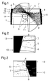
- Figure 1 shows a side view of a first throttle device according to the invention in a sectional view, wherein both the fully closed and the open position and the contour line of the flap movement are shown in the figure.
- Figure 2 shows a section of the first throttle blade of the throttle valve device of Figure 1 in the closed position.
- FIG. 3 shows the corresponding section of the opposite throttling blade of the throttle valve device from FIG. 1 in the closed position.
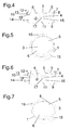
- Figure 4 shows a side view of a second throttle valve device according to the invention in the closed state in a sectional view.
- FIG. 5 shows a three-dimensional view of the throttle body of FIG. 4.
- FIG. 6 shows a side view of the throttle body of FIG. 5, with the throttle body partially open.
- FIG. 7 shows a three-dimensional representation of the throttle valve device according to FIG. 6.
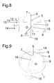
- Figure 8 shows a side view of the throttle valve device according to the figure 4, with a throttle body in the fully open position.
- FIG. 9 shows a three-dimensional illustration of the throttle valve device according to FIG. 8.
- the throttle device according to the invention shown in Figures 1 to 9 each consist of a housing 1 which is formed substantially rotationally symmetrical and in the interior of which a fluid-flow channel 2 through the housing 1 is formed.
- a double-wing throttle body 3 is arranged, which is pivotable about a rotation axis 4.
- the throttle body 3 is shown both in the channel 2 completely closing position and fully releasing position. Furthermore, the contour of the movement line is shown when opening.
- the throttle body 3 consists of a first wing 5 and a second wing 6, which are arranged in the illustration left or right of the rotation axis 4, so that upon rotation of the throttle body 3 from the closed position of the first wing 5 according to the figure 1 is rotated above and the second wing 6 is rotated downwards, ie to the axis of rotation.
- these two wings 5, 6 thus consist of different circular sections, which together form a circle of uniform diameter, since the axis of rotation 4 is arranged axially offset both in the channel to the throttle body 3 and radially offset from the center of the throttle body 3.
- the throttle body 3 has a radial peripheral surface 7, which is formed in a spherical-sectional shape. This means that the radial peripheral surface 7 has a radius which can be arranged, for example, approximately in the region of the axis of rotation 4 of the throttle body 3.
- the throttle body 3 In the closing of the channel 2 state, the throttle body 3 is located with its radial peripheral surface 7 against a seat 8, which is formed by an inner wall 9 of the channel 2 forming the housing 1 at. In particular, in Figures 2 and 3 it can be seen that this is a line contact between the seat surface 8 and circumferential surface 7.
- FIGS. 2 and 3 it is further illustrated how the radial circumferential surface 7 moves away from the inner wall 9 of the housing 1 when the throttle body 3 rotates.
- the channel 2 has a section 10 with a cross-section widening in the direction of the axis of rotation 4. That this is necessary for the movement of the throttle body 3 becomes clear, in particular, from FIG. 3, since the second vane 6 in the first rotation angle range initially turns slightly away from a channel axis 11 during rotation.
- the widening section 10 in the region of the second wing 6 should in particular be designed so that an exact adjustment of the fluid flow is achieved upon rotation of the wing 6, that is, the function of a ball zone of a known throttle body is simulated.
- the section 10 extends approximately from the seat surface 8 up to the level of the rotation axis 4, which should correspond at least to an area which is axially swept over by the throttle body 3 with a rotation of approximately 10 ° from the closed position.
- the fluid flowed through channel 2 has in accordance with the safe operation, but also for precise control of the amount of fluid through sections of varying cross-section.
- the channel initially has a first section 12 with a narrower cross section. This first extends slightly in a second section 13 on the side facing the first wing 5 in the direction of the axis of rotation 4, while the side facing the wing 6 of the channel 2 is further limited by a largely straight wall.
- This section 13 is used in particular to ensure at angles of rotation of up to at least 10 ° from the closed position of the throttle body 3, a precise dosage of the delivered fluid amount and thus again the same function as the other applications known ball zones in throttle body.
- This section 13 is limited by the seat surface 8, against which the throttle body 3 or its radial peripheral surface 7 rests in the closed state.
- the previously described widening third section 10 connects, which must be formed in particular on the side facing the second wing 6 side.
- a further enlargement can take place on the side lying to the first wing 5.
- This widening section 10 extends approximately to the level of the axis of rotation 4, and from here passes into a fourth section 14 which has an approximately constant cross-section.
- FIGS. 4 to 9 show a further throttle valve device according to the invention, the throttle body 3 being shown in the closed state in FIGS. 4 and 5, in the slightly opened state in FIGS. 6 and 7, ie by a rotation of approximately 10 ° and in FIG Figures 8 and 9 in the open state.
- the throttle body 3 here also has a spherical-section-shaped peripheral surface 7, to which, however, in the direction of the rotation axis 4, a further straight peripheral surface 19 of smaller diameter follows.
- the axis of rotation 4 is arranged to the opposite side, that is to say offset to the right. It can also be seen that the housing 1 is approximately rotationally symmetrical, whereby a delay due to heat or the like is significantly reduced.
- the shape of the inner wall can be adapted to the movement of the throttle body 3 depending on the eccentricity in order to obtain the smallest possible changes in the free cross section and thus allow accurate fluid quantity control. It is crucial that there are no undercuts in the entire area of the housing 1, as is usual in the case of spherical zones, but an overall steadily progressing expansion is given in one direction. This allows a production of such a fluid-flow channel 2 and the housing 1 and the throttle body 3 arranged therein in the assembly spraying method, since the demolding can be done easily by simply pulling out the slide. Also, it is of course possible to produce such a throttle device in a rectangular channel with a rectangular throttle body.
Landscapes
- Engineering & Computer Science (AREA)
- Mechanical Engineering (AREA)
- Chemical & Material Sciences (AREA)
- Combustion & Propulsion (AREA)
- General Engineering & Computer Science (AREA)
- Manufacturing & Machinery (AREA)
- Lift Valve (AREA)
- Control Of Throttle Valves Provided In The Intake System Or In The Exhaust System (AREA)
Applications Claiming Priority (1)
| Application Number | Priority Date | Filing Date | Title |
|---|---|---|---|
| DE102006045420A DE102006045420A1 (de) | 2006-09-26 | 2006-09-26 | Drosselklappenvorrichtung für eine Verbrennungskraftmaschine |
Publications (2)
| Publication Number | Publication Date |
|---|---|
| EP1909005A1 true EP1909005A1 (fr) | 2008-04-09 |
| EP1909005B1 EP1909005B1 (fr) | 2010-10-20 |
Family
ID=38510406
Family Applications (1)
| Application Number | Title | Priority Date | Filing Date |
|---|---|---|---|
| EP07113680A Not-in-force EP1909005B1 (fr) | 2006-09-26 | 2007-08-02 | Dispositif de vanne papillon pour un moteur à combustion interne |
Country Status (4)
| Country | Link |
|---|---|
| US (1) | US7546828B2 (fr) |
| EP (1) | EP1909005B1 (fr) |
| AT (1) | ATE485469T1 (fr) |
| DE (2) | DE102006045420A1 (fr) |
Families Citing this family (10)
| Publication number | Priority date | Publication date | Assignee | Title |
|---|---|---|---|---|
| US20100313848A1 (en) * | 2009-06-16 | 2010-12-16 | Hatton Ronald E | Throttle body and a method to modify a throttle body |
| JP2012180798A (ja) * | 2011-03-02 | 2012-09-20 | Honda Motor Co Ltd | 車両の吸気装置 |
| US9233493B2 (en) * | 2011-09-29 | 2016-01-12 | Electrojet, Inc. | Throttle body with blade and shaft injection molded within the body |
| DE112014006049T5 (de) * | 2013-12-25 | 2016-09-08 | Aisan Kogyo Kabushiki Kaisha | Doppelexzentrisches Ventil |
| CN105874250B (zh) * | 2013-12-25 | 2018-02-27 | 爱三工业株式会社 | 双偏心阀 |
| IN2015DE00283A (fr) * | 2014-02-28 | 2015-09-04 | Borgwarner Inc | |
| DE102016110998A1 (de) * | 2016-06-15 | 2017-12-21 | Fischer Rohrtechnik Gmbh | Drosselklappenanordnung und Verfahren zur Herstellung einer Drosselklappenanordnung |
| JP6768427B2 (ja) * | 2016-06-01 | 2020-10-14 | 愛三工業株式会社 | 二重偏心弁 |
| EP3921529A1 (fr) | 2019-02-05 | 2021-12-15 | Pierburg GmbH | Dispositif formant volet pour moteur à combustion interne |
| US11149656B1 (en) | 2020-12-08 | 2021-10-19 | Ford Global Technologies, Llc | Engine throttle body hydrocarbon emissions reduction system |
Citations (9)
| Publication number | Priority date | Publication date | Assignee | Title |
|---|---|---|---|---|
| US3475007A (en) | 1966-08-19 | 1969-10-28 | Pratt Co Henry | Skewed seat butterfly valve |
| US3945398A (en) * | 1973-06-29 | 1976-03-23 | Henry Masheder | Check valves |
| US4284264A (en) * | 1980-01-17 | 1981-08-18 | Aktiebolaget Somas Ventiler | Butterfly valves |
| GB2092714A (en) * | 1978-03-10 | 1982-08-18 | Adams Araturen N Apparate Gebr | Seal rings for use in disc valves |
| EP0471270A1 (fr) | 1990-08-16 | 1992-02-19 | XOMOX INTERNATIONAL GMBH & CO. | Clapet d'arrêt |
| EP0482272B1 (fr) | 1990-10-24 | 1995-06-28 | Ab Volvo | Ensemble de vanne |
| DE19840887A1 (de) | 1998-09-09 | 2000-03-16 | Bosch Gmbh Robert | Drosselklappenstutzen zum Steuern der Leistung einer Brennkraftmaschine und Verfahren zum Einstellen einer Leckluft |
| WO2003019055A1 (fr) * | 2001-08-25 | 2003-03-06 | Arena Ibc Limited | Ensemble soupape pour contenants |
| DE102005023613B3 (de) | 2005-05-20 | 2006-09-07 | Pierburg Gmbh | Verfahren zur Herstellung eines modularen Klappenstutzens für Drossel-, Stell- oder Regelklappen in einer Verbrennungskraftmaschine |
Family Cites Families (12)
| Publication number | Priority date | Publication date | Assignee | Title |
|---|---|---|---|---|
| DE2023960A1 (de) * | 1970-05-15 | 1971-11-25 | Masheder Design Studies Ltd | Klappenventil |
| FR2554539B1 (fr) * | 1983-11-07 | 1986-01-31 | Verdelet Alain | Vanne a papillon perfectionnee |
| SE445382B (sv) * | 1984-09-27 | 1986-06-16 | Somas Ventiler | Tetningsanordning vid spjellventiler |
| JPS61252971A (ja) | 1985-04-29 | 1986-11-10 | Ryozo Oota | 球面シ−ト形バタフライバルブ |
| SE456112C (sv) * | 1987-01-02 | 1996-04-29 | Somas Ventiler | Vridspjällsventil |
| US4860706A (en) * | 1987-09-14 | 1989-08-29 | Aisan Kogyo Kabushiki Kaisha | Throttle body |
| JP2787726B2 (ja) | 1990-05-31 | 1998-08-20 | 株式会社エヌビーエス | バタフライバルブ |
| JP3712533B2 (ja) * | 1998-06-30 | 2005-11-02 | 愛三工業株式会社 | 内燃機関の吸気制御バルブ装置 |
| DE19909982A1 (de) * | 1999-03-06 | 2000-09-07 | Bosch Gmbh Robert | Drosselklappenstutzen zum Steuern der Leistung einer Brennkraftmaschine |
| JP3726815B2 (ja) * | 2003-02-13 | 2005-12-14 | 大豊工業株式会社 | 流量制御バルブ |
| JP4515075B2 (ja) * | 2003-11-07 | 2010-07-28 | 株式会社デンソー | 内燃機関用スロットル装置の射出成形方法 |
| DE10353431B4 (de) * | 2003-11-15 | 2005-12-08 | Pierburg Gmbh | Wellendurchführung an einem Luftansaugkanalsystem |
-
2006
- 2006-09-26 DE DE102006045420A patent/DE102006045420A1/de not_active Ceased
-
2007
- 2007-08-02 DE DE502007005394T patent/DE502007005394D1/de active Active
- 2007-08-02 AT AT07113680T patent/ATE485469T1/de active
- 2007-08-02 EP EP07113680A patent/EP1909005B1/fr not_active Not-in-force
- 2007-09-26 US US11/862,112 patent/US7546828B2/en active Active
Patent Citations (9)
| Publication number | Priority date | Publication date | Assignee | Title |
|---|---|---|---|---|
| US3475007A (en) | 1966-08-19 | 1969-10-28 | Pratt Co Henry | Skewed seat butterfly valve |
| US3945398A (en) * | 1973-06-29 | 1976-03-23 | Henry Masheder | Check valves |
| GB2092714A (en) * | 1978-03-10 | 1982-08-18 | Adams Araturen N Apparate Gebr | Seal rings for use in disc valves |
| US4284264A (en) * | 1980-01-17 | 1981-08-18 | Aktiebolaget Somas Ventiler | Butterfly valves |
| EP0471270A1 (fr) | 1990-08-16 | 1992-02-19 | XOMOX INTERNATIONAL GMBH & CO. | Clapet d'arrêt |
| EP0482272B1 (fr) | 1990-10-24 | 1995-06-28 | Ab Volvo | Ensemble de vanne |
| DE19840887A1 (de) | 1998-09-09 | 2000-03-16 | Bosch Gmbh Robert | Drosselklappenstutzen zum Steuern der Leistung einer Brennkraftmaschine und Verfahren zum Einstellen einer Leckluft |
| WO2003019055A1 (fr) * | 2001-08-25 | 2003-03-06 | Arena Ibc Limited | Ensemble soupape pour contenants |
| DE102005023613B3 (de) | 2005-05-20 | 2006-09-07 | Pierburg Gmbh | Verfahren zur Herstellung eines modularen Klappenstutzens für Drossel-, Stell- oder Regelklappen in einer Verbrennungskraftmaschine |
Also Published As
| Publication number | Publication date |
|---|---|
| US7546828B2 (en) | 2009-06-16 |
| EP1909005B1 (fr) | 2010-10-20 |
| DE502007005394D1 (de) | 2010-12-02 |
| DE102006045420A1 (de) | 2008-04-10 |
| US20080072873A1 (en) | 2008-03-27 |
| ATE485469T1 (de) | 2010-11-15 |
Similar Documents
| Publication | Publication Date | Title |
|---|---|---|
| EP1909005B1 (fr) | Dispositif de vanne papillon pour un moteur à combustion interne | |
| DE102014114968B4 (de) | Regelvorrichtung für eine Verbrennungskraftmaschine | |
| EP2728156B1 (fr) | Dispositif de réglage pour un moteur à combustion interne | |
| DE4334180A1 (de) | Drosselvorrichtung | |
| WO2008058779A1 (fr) | Dispositif de régulation pour un moteur à combustion interne | |
| DE102007033675A1 (de) | Abgasrückführvorrichtung für eine Verbrennungskraftmaschine | |
| EP0889269A1 (fr) | Robinet réglable à tournant sphérique | |
| DE102012103311B4 (de) | Ventilvorrichtung für eine Verbrennungskraftmaschine | |
| DE4431711A1 (de) | Vorrichtung zur Regelung der Leerlaufdrehzahl einer Brennkraftmaschine | |
| DE19959109B4 (de) | Drehklappenventil | |
| EP3615787B1 (fr) | Vanne pour un moteur à combustion interne | |
| EP2196654A2 (fr) | Dispositif de vanne papillon | |
| EP1927746A1 (fr) | Dispositif de contrôle de l'échappement d'un moteur à combustion interne | |
| EP1503062A1 (fr) | Dispositif d'obturation d'un écoulement de fluide | |
| EP1657424B1 (fr) | Dispositif de recirculation de gaz d'échappement pour un moteur à combustion interne | |
| EP2726720B1 (fr) | Procédé d'assemblage par moulage par injection, sans fente de deux éléments ainsi que dispositif de clapet destiné à un moteur à combustion interne | |
| DE102015111252B4 (de) | Ventil für einen Abgasstrang einer Brennkraftmaschine | |
| DE2053132C3 (de) | Luftmengenmesser für eine Brennkraftmaschine zur Regelung der Kraftstoffzufuhr | |
| EP3538753B1 (fr) | Dispositif de commande pour un moteur à combustion interne | |
| EP3212913B1 (fr) | Système à clapet pour un moteur à combustion interne et méthode pour fabriquer un tel clapet | |
| WO2015106857A1 (fr) | Support de papillon pour moteur à combustion interne |
Legal Events
| Date | Code | Title | Description |
|---|---|---|---|
| PUAI | Public reference made under article 153(3) epc to a published international application that has entered the european phase |
Free format text: ORIGINAL CODE: 0009012 |
|
| 17P | Request for examination filed |
Effective date: 20070802 |
|
| AK | Designated contracting states |
Kind code of ref document: A1 Designated state(s): AT BE BG CH CY CZ DE DK EE ES FI FR GB GR HU IE IS IT LI LT LU LV MC MT NL PL PT RO SE SI SK TR |
|
| AX | Request for extension of the european patent |
Extension state: AL BA HR MK RS |
|
| 17Q | First examination report despatched |
Effective date: 20080530 |
|
| AKX | Designation fees paid |
Designated state(s): AT BE BG CH CY CZ DE DK EE ES FI FR GB GR HU IE IS IT LI LT LU LV MC MT NL PL PT RO SE SI SK TR |
|
| GRAP | Despatch of communication of intention to grant a patent |
Free format text: ORIGINAL CODE: EPIDOSNIGR1 |
|
| GRAS | Grant fee paid |
Free format text: ORIGINAL CODE: EPIDOSNIGR3 |
|
| GRAA | (expected) grant |
Free format text: ORIGINAL CODE: 0009210 |
|
| AK | Designated contracting states |
Kind code of ref document: B1 Designated state(s): AT BE BG CH CY CZ DE DK EE ES FI FR GB GR HU IE IS IT LI LT LU LV MC MT NL PL PT RO SE SI SK TR |
|
| REG | Reference to a national code |
Ref country code: GB Ref legal event code: FG4D Free format text: NOT ENGLISH |
|
| REG | Reference to a national code |
Ref country code: CH Ref legal event code: EP |
|
| REG | Reference to a national code |
Ref country code: IE Ref legal event code: FG4D Free format text: LANGUAGE OF EP DOCUMENT: GERMAN |
|
| REF | Corresponds to: |
Ref document number: 502007005394 Country of ref document: DE Date of ref document: 20101202 Kind code of ref document: P |
|
| REG | Reference to a national code |
Ref country code: SE Ref legal event code: TRGR |
|
| REG | Reference to a national code |
Ref country code: NL Ref legal event code: VDEP Effective date: 20101020 |
|
| LTIE | Lt: invalidation of european patent or patent extension |
Effective date: 20101020 |
|
| PG25 | Lapsed in a contracting state [announced via postgrant information from national office to epo] |
Ref country code: LT Free format text: LAPSE BECAUSE OF FAILURE TO SUBMIT A TRANSLATION OF THE DESCRIPTION OR TO PAY THE FEE WITHIN THE PRESCRIBED TIME-LIMIT Effective date: 20101020 |
|
| REG | Reference to a national code |
Ref country code: IE Ref legal event code: FD4D |
|
| PG25 | Lapsed in a contracting state [announced via postgrant information from national office to epo] |
Ref country code: NL Free format text: LAPSE BECAUSE OF FAILURE TO SUBMIT A TRANSLATION OF THE DESCRIPTION OR TO PAY THE FEE WITHIN THE PRESCRIBED TIME-LIMIT Effective date: 20101020 Ref country code: PT Free format text: LAPSE BECAUSE OF FAILURE TO SUBMIT A TRANSLATION OF THE DESCRIPTION OR TO PAY THE FEE WITHIN THE PRESCRIBED TIME-LIMIT Effective date: 20110221 Ref country code: IS Free format text: LAPSE BECAUSE OF FAILURE TO SUBMIT A TRANSLATION OF THE DESCRIPTION OR TO PAY THE FEE WITHIN THE PRESCRIBED TIME-LIMIT Effective date: 20110220 Ref country code: SI Free format text: LAPSE BECAUSE OF FAILURE TO SUBMIT A TRANSLATION OF THE DESCRIPTION OR TO PAY THE FEE WITHIN THE PRESCRIBED TIME-LIMIT Effective date: 20101020 Ref country code: FI Free format text: LAPSE BECAUSE OF FAILURE TO SUBMIT A TRANSLATION OF THE DESCRIPTION OR TO PAY THE FEE WITHIN THE PRESCRIBED TIME-LIMIT Effective date: 20101020 Ref country code: BG Free format text: LAPSE BECAUSE OF FAILURE TO SUBMIT A TRANSLATION OF THE DESCRIPTION OR TO PAY THE FEE WITHIN THE PRESCRIBED TIME-LIMIT Effective date: 20110120 Ref country code: LV Free format text: LAPSE BECAUSE OF FAILURE TO SUBMIT A TRANSLATION OF THE DESCRIPTION OR TO PAY THE FEE WITHIN THE PRESCRIBED TIME-LIMIT Effective date: 20101020 |
|
| PG25 | Lapsed in a contracting state [announced via postgrant information from national office to epo] |
Ref country code: GR Free format text: LAPSE BECAUSE OF FAILURE TO SUBMIT A TRANSLATION OF THE DESCRIPTION OR TO PAY THE FEE WITHIN THE PRESCRIBED TIME-LIMIT Effective date: 20110121 |
|
| PG25 | Lapsed in a contracting state [announced via postgrant information from national office to epo] |
Ref country code: ES Free format text: LAPSE BECAUSE OF FAILURE TO SUBMIT A TRANSLATION OF THE DESCRIPTION OR TO PAY THE FEE WITHIN THE PRESCRIBED TIME-LIMIT Effective date: 20110131 Ref country code: IE Free format text: LAPSE BECAUSE OF FAILURE TO SUBMIT A TRANSLATION OF THE DESCRIPTION OR TO PAY THE FEE WITHIN THE PRESCRIBED TIME-LIMIT Effective date: 20101020 Ref country code: CZ Free format text: LAPSE BECAUSE OF FAILURE TO SUBMIT A TRANSLATION OF THE DESCRIPTION OR TO PAY THE FEE WITHIN THE PRESCRIBED TIME-LIMIT Effective date: 20101020 Ref country code: EE Free format text: LAPSE BECAUSE OF FAILURE TO SUBMIT A TRANSLATION OF THE DESCRIPTION OR TO PAY THE FEE WITHIN THE PRESCRIBED TIME-LIMIT Effective date: 20101020 |
|
| PLBE | No opposition filed within time limit |
Free format text: ORIGINAL CODE: 0009261 |
|
| STAA | Information on the status of an ep patent application or granted ep patent |
Free format text: STATUS: NO OPPOSITION FILED WITHIN TIME LIMIT |
|
| PG25 | Lapsed in a contracting state [announced via postgrant information from national office to epo] |
Ref country code: SK Free format text: LAPSE BECAUSE OF FAILURE TO SUBMIT A TRANSLATION OF THE DESCRIPTION OR TO PAY THE FEE WITHIN THE PRESCRIBED TIME-LIMIT Effective date: 20101020 Ref country code: RO Free format text: LAPSE BECAUSE OF FAILURE TO SUBMIT A TRANSLATION OF THE DESCRIPTION OR TO PAY THE FEE WITHIN THE PRESCRIBED TIME-LIMIT Effective date: 20101020 Ref country code: DK Free format text: LAPSE BECAUSE OF FAILURE TO SUBMIT A TRANSLATION OF THE DESCRIPTION OR TO PAY THE FEE WITHIN THE PRESCRIBED TIME-LIMIT Effective date: 20101020 Ref country code: PL Free format text: LAPSE BECAUSE OF FAILURE TO SUBMIT A TRANSLATION OF THE DESCRIPTION OR TO PAY THE FEE WITHIN THE PRESCRIBED TIME-LIMIT Effective date: 20101020 |
|
| 26N | No opposition filed |
Effective date: 20110721 |
|
| REG | Reference to a national code |
Ref country code: DE Ref legal event code: R097 Ref document number: 502007005394 Country of ref document: DE Effective date: 20110721 |
|
| PGFP | Annual fee paid to national office [announced via postgrant information from national office to epo] |
Ref country code: SE Payment date: 20110823 Year of fee payment: 5 |
|
| PG25 | Lapsed in a contracting state [announced via postgrant information from national office to epo] |
Ref country code: MT Free format text: LAPSE BECAUSE OF FAILURE TO SUBMIT A TRANSLATION OF THE DESCRIPTION OR TO PAY THE FEE WITHIN THE PRESCRIBED TIME-LIMIT Effective date: 20101020 |
|
| PGFP | Annual fee paid to national office [announced via postgrant information from national office to epo] |
Ref country code: IT Payment date: 20110825 Year of fee payment: 5 |
|
| BERE | Be: lapsed |
Owner name: PIERBURG G.M.B.H. Effective date: 20110831 |
|
| PG25 | Lapsed in a contracting state [announced via postgrant information from national office to epo] |
Ref country code: MC Free format text: LAPSE BECAUSE OF NON-PAYMENT OF DUE FEES Effective date: 20110831 |
|
| REG | Reference to a national code |
Ref country code: CH Ref legal event code: PL |
|
| GBPC | Gb: european patent ceased through non-payment of renewal fee |
Effective date: 20110802 |
|
| PG25 | Lapsed in a contracting state [announced via postgrant information from national office to epo] |
Ref country code: CH Free format text: LAPSE BECAUSE OF NON-PAYMENT OF DUE FEES Effective date: 20110831 Ref country code: LI Free format text: LAPSE BECAUSE OF NON-PAYMENT OF DUE FEES Effective date: 20110831 |
|
| PG25 | Lapsed in a contracting state [announced via postgrant information from national office to epo] |
Ref country code: BE Free format text: LAPSE BECAUSE OF NON-PAYMENT OF DUE FEES Effective date: 20110831 |
|
| PG25 | Lapsed in a contracting state [announced via postgrant information from national office to epo] |
Ref country code: GB Free format text: LAPSE BECAUSE OF NON-PAYMENT OF DUE FEES Effective date: 20110802 |
|
| PGFP | Annual fee paid to national office [announced via postgrant information from national office to epo] |
Ref country code: AT Payment date: 20120822 Year of fee payment: 6 |
|
| REG | Reference to a national code |
Ref country code: SE Ref legal event code: EUG |
|
| PG25 | Lapsed in a contracting state [announced via postgrant information from national office to epo] |
Ref country code: SE Free format text: LAPSE BECAUSE OF NON-PAYMENT OF DUE FEES Effective date: 20120803 |
|
| PG25 | Lapsed in a contracting state [announced via postgrant information from national office to epo] |
Ref country code: LU Free format text: LAPSE BECAUSE OF NON-PAYMENT OF DUE FEES Effective date: 20110802 Ref country code: CY Free format text: LAPSE BECAUSE OF EXPIRATION OF PROTECTION Effective date: 20101020 Ref country code: IT Free format text: LAPSE BECAUSE OF NON-PAYMENT OF DUE FEES Effective date: 20120802 |
|
| PG25 | Lapsed in a contracting state [announced via postgrant information from national office to epo] |
Ref country code: TR Free format text: LAPSE BECAUSE OF FAILURE TO SUBMIT A TRANSLATION OF THE DESCRIPTION OR TO PAY THE FEE WITHIN THE PRESCRIBED TIME-LIMIT Effective date: 20101020 |
|
| PG25 | Lapsed in a contracting state [announced via postgrant information from national office to epo] |
Ref country code: HU Free format text: LAPSE BECAUSE OF FAILURE TO SUBMIT A TRANSLATION OF THE DESCRIPTION OR TO PAY THE FEE WITHIN THE PRESCRIBED TIME-LIMIT Effective date: 20101020 |
|
| REG | Reference to a national code |
Ref country code: AT Ref legal event code: MM01 Ref document number: 485469 Country of ref document: AT Kind code of ref document: T Effective date: 20130802 |
|
| PG25 | Lapsed in a contracting state [announced via postgrant information from national office to epo] |
Ref country code: AT Free format text: LAPSE BECAUSE OF NON-PAYMENT OF DUE FEES Effective date: 20130802 |
|
| REG | Reference to a national code |
Ref country code: FR Ref legal event code: PLFP Year of fee payment: 10 |
|
| REG | Reference to a national code |
Ref country code: FR Ref legal event code: PLFP Year of fee payment: 11 |
|
| PGFP | Annual fee paid to national office [announced via postgrant information from national office to epo] |
Ref country code: SK Payment date: 20170602 Year of fee payment: 6 |
|
| PG25 | Lapsed in a contracting state [announced via postgrant information from national office to epo] |
Ref country code: FR Free format text: LAPSE BECAUSE OF NON-PAYMENT OF DUE FEES Effective date: 20180831 |
|
| REG | Reference to a national code |
Ref country code: DE Ref legal event code: R082 Ref document number: 502007005394 Country of ref document: DE Representative=s name: TERPATENT PARTGMBB, DE Ref country code: DE Ref legal event code: R082 Ref document number: 502007005394 Country of ref document: DE Representative=s name: TERPATENT PATENTANWAELTE TER SMITTEN EBERLEIN-, DE |
|
| PGFP | Annual fee paid to national office [announced via postgrant information from national office to epo] |
Ref country code: DE Payment date: 20230822 Year of fee payment: 17 |
|
| REG | Reference to a national code |
Ref country code: DE Ref legal event code: R119 Ref document number: 502007005394 Country of ref document: DE |
|
| PG25 | Lapsed in a contracting state [announced via postgrant information from national office to epo] |
Ref country code: DE Free format text: LAPSE BECAUSE OF NON-PAYMENT OF DUE FEES Effective date: 20250301 |